JP5742108B2 - Water heater - Google Patents
Water heater Download PDFInfo
- Publication number
- JP5742108B2 JP5742108B2 JP2010087638A JP2010087638A JP5742108B2 JP 5742108 B2 JP5742108 B2 JP 5742108B2 JP 2010087638 A JP2010087638 A JP 2010087638A JP 2010087638 A JP2010087638 A JP 2010087638A JP 5742108 B2 JP5742108 B2 JP 5742108B2
- Authority
- JP
- Japan
- Prior art keywords
- hot water
- temperature
- storage tank
- water storage
- discharged
- Prior art date
- Legal status (The legal status is an assumption and is not a legal conclusion. Google has not performed a legal analysis and makes no representation as to the accuracy of the status listed.)
- Active
Links
Images


Description
本発明は、貯湯タンク内の湯を、給湯だけでなく、風呂追焚、風呂保温または温水暖房などにも使用する給湯装置に関する。 The present invention relates to a hot water supply apparatus that uses hot water in a hot water storage tank not only for hot water supply but also for bath remedy, bath heat insulation or hot water heating.
給湯装置のなかには、貯湯タンク内の湯を、給湯だけでなく、風呂追焚、風呂保温または温水床暖房などにも使用するものがある。この様な給湯装置では、熱交換器を備えており、例えば風呂追焚または風呂保温の場合は、浴槽内の水または低中湯水(以後、湯水と呼ぶ)を浴槽と熱交換器との間で循環させると共に、貯湯タンク内の湯(高温水)を貯湯タンクと熱交換器との間で循環させて、熱交換器において、貯湯タンクからの湯の熱により浴槽からの湯水を加熱する。 Some hot water supply apparatuses use hot water in a hot water storage tank not only for hot water supply, but also for bath memorial, bath heat insulation or hot water floor heating. Such a hot water supply apparatus is provided with a heat exchanger. For example, in the case of bath remedy or bath insulation, the water in the bathtub or the low and middle hot water (hereinafter referred to as hot water) is provided between the bathtub and the heat exchanger. The hot water (hot water) in the hot water storage tank is circulated between the hot water storage tank and the heat exchanger, and the hot water from the bathtub is heated by the heat of the hot water from the hot water storage tank in the heat exchanger.
尚、温水暖房の場合も、風呂追焚または風呂保温の場合と同様に、温水暖房器からの暖房用液体を温水暖房器と熱交換器との間で循環させて、熱交換器において、貯湯タンクからの湯の熱により暖房用液体を加熱する。 In addition, in the case of hot water heating, as in the case of bath remedy or bath insulation, the liquid for heating from the hot water heater is circulated between the hot water heater and the heat exchanger, and in the heat exchanger, The heating liquid is heated by the hot water from the tank.
またこの様な給湯装置では、熱交換器からの熱交換後の湯(中低温水)は、貯湯タンクの下部に戻されて、貯湯タンクの下部に貯まった湯水と混合される。 In such a hot water supply apparatus, the hot water (medium / low temperature water) after the heat exchange from the heat exchanger is returned to the lower part of the hot water storage tank and mixed with the hot water stored in the lower part of the hot water storage tank.
尚、貯湯タンクの下部に貯まった湯水は、加熱手段に送られて加熱されて所定温度の湯(高温水)にされた後、貯湯タンクの上部から貯湯タンク内に戻される。 The hot water stored in the lower part of the hot water storage tank is sent to the heating means and heated to be heated to a predetermined temperature (hot water), and then returned to the hot water storage tank from the upper part of the hot water storage tank.
この様な給湯装置に関する先行技術文献として、例えば特許文献1が知られている。
For example,
上記の様な給湯装置では、風呂追焚、風呂保温または温水暖房などを長時間行うと、貯湯タンク内の湯が減少するので、給湯可能な蓄熱量が低下して給湯時に湯切れが発生し易くなるという問題があった。 In a hot water supply system such as the one described above, if bath bathing, bath thermal insulation or hot water heating is performed for a long time, the amount of hot water in the hot water storage tank decreases, so the amount of heat storage that can be hot water decreases and hot water runs out during hot water supply. There was a problem that it was easy.
尚、この湯切れの問題については、貯湯タンクの容量を大きくすることで対処できる。しかし給湯用の湯の温度は90°程度の高温に設定されるので、貯湯タンクの容量が大きくなると、貯湯タンク内の湯からの放熱損失が大きくなるという新たな問題が発生する。 The problem of running out of hot water can be dealt with by increasing the capacity of the hot water storage tank. However, since the temperature of the hot water for hot water supply is set to a high temperature of about 90 °, a new problem arises that if the capacity of the hot water storage tank increases, the heat dissipation loss from the hot water in the hot water storage tank increases.
また風呂追焚、風呂保温または温水暖房などを長時間行うと、熱交換器からの中低温水が貯湯タンク内に多く貯まり、貯湯タンクの下部の湯水と混ざることで、貯湯タンクの下部の湯水の温度が上昇する。この上昇により、加熱手段により貯湯タンク内の湯水を加熱する際の加熱効率が低下するという問題があった。 Also, if you perform bath memorial, bath warming or hot water heating for a long time, a lot of medium and low temperature water from the heat exchanger is stored in the hot water tank and mixed with the hot water at the bottom of the hot water tank, so the hot water at the bottom of the hot water tank Temperature rises. Due to this increase, there is a problem that the heating efficiency when heating the hot water in the hot water storage tank by the heating means is lowered.
この発明の課題は、上記のような問題点を解決するためになされたものであり、第1に、給湯時の湯切れを防止できる給湯装置を提供すること、第2に、貯湯タンク内の湯からの放熱損失を低減できる給湯装置を提供すること、第3に、加熱手段の加熱効率の低下を防止できる給湯装置を提供することにある。 An object of the present invention is to solve the above-mentioned problems. First, to provide a hot water supply device that can prevent hot water shortage during hot water supply, and secondly, in a hot water storage tank. A third object of the present invention is to provide a hot water supply apparatus capable of reducing heat dissipation loss from hot water, and thirdly, to provide a hot water supply apparatus capable of preventing a decrease in heating efficiency of the heating means.
上記課題を解決する為に、本発明の第1乃至第6の態様は、熱交換器(3)と、第1温度の湯が貯湯され、その湯が所定の給湯器(5)から出湯される給湯用の第1貯湯タンク(7)と、第2温度の湯が貯湯され、その湯が前記熱交換器に循環されて前記熱交換器を加熱する熱交換用の第2貯湯タンク(9)と、前記第1貯湯タンク(7)および前記第2貯湯タンク(9)の湯水を加熱する加熱手段(11)と、前記加熱手段から出湯される湯の温度を前記第1温度または前記第2温度に制御する第1制御手段(27e,27j)と、前記加熱手段から出湯される前記第1温度の湯の前記第1貯湯タンクへの入湯と、前記加熱手段から出湯される前記第2温度の湯の前記第2貯湯タンクへの入湯とを切り換える第1弁(B1)と備えるものである。そして前記第1温度と前記第2温度とが異なる。
そして本発明の第1の態様は、前記第1貯湯タンク(7)の上部から出湯される湯と前記第2貯湯タンク(9)の下部から排出される湯水とを混合し又は選択的に前記所定の給湯器(5)から排出する第2弁(B2)を更に備える。
In order to solve the above problems, according to the first to sixth aspects of the present invention, a heat exchanger (3) and hot water having a first temperature are stored, and the hot water is discharged from a predetermined water heater (5). A first hot water storage tank (7) for hot water supply and a second hot water storage tank for heat exchange (9) for storing hot water at a second temperature and circulating the hot water to the heat exchanger to heat the heat exchanger. ), Heating means (11) for heating the hot water in the first hot water storage tank (7) and the second hot water storage tank (9), and the temperature of hot water discharged from the heating means is the first temperature or the first temperature. First control means (27e, 27j) for controlling to two temperatures, hot water of the first temperature discharged from the heating means into the first hot water storage tank, and second hot water discharged from the heating means. A first valve (B1) for switching hot water of temperature into the second hot water storage tank; That. The first temperature and the second temperature are different.
And the 1st aspect of this invention mixes the hot water discharged from the upper part of the said 1st hot water storage tank (7), and the hot water discharged | emitted from the lower part of the said 2nd hot water storage tank (9), or selectively said A second valve (B2) for discharging from the predetermined water heater (5) is further provided.
本発明の第2の態様は、第1の態様に記載の給湯装置であって、前記第2温度は前記第1温度よりも低いものである。 A second aspect of the present invention is the hot water supply apparatus according to the first aspect, wherein the second temperature is lower than the first temperature.
本発明の第3の態様は、第1の態様に記載の給湯装置であって、前記第1温度は前記第2温度よりも低いものである。 A third aspect of the present invention is the hot water supply apparatus according to the first aspect, wherein the first temperature is lower than the second temperature.
本発明の第4の態様は、外気温を検出する温度検出手段(17)と、前記温度検出手段により検出された温度に応じて前記第1温度および/または前記第2温度の設定温度を変更する設定温度変更手段(27g)と、を更に備えるものである。 According to a fourth aspect of the present invention , there is provided temperature detection means (17) for detecting an outside air temperature, and the set temperature of the first temperature and / or the second temperature is changed according to the temperature detected by the temperature detection means. And a set temperature changing means (27g).
本発明の第5の態様は、前記第1貯湯タンク(7)の上部から出湯される湯と前記第2貯湯タンク(9)の上部から出湯される湯とを混合し又は選択的に前記所定の給湯器(5)から出湯する第3弁(B3)を更に備える。そして前記熱交換器(3)において前記第2貯湯タンク(9)から循環される前記第2温度の湯と所定の温水暖房器(19)から循環される暖房用液体との間で熱交換が行われる場合において、前記所定の温水暖房器に設定された暖房温度に基づいて前記第2温度の設定温度を変更する設定温度変更手段(27h)を更に備えるものである。 According to a fifth aspect of the present invention, hot water discharged from an upper portion of the first hot water storage tank (7) and hot water discharged from an upper portion of the second hot water storage tank (9) are mixed or selectively selected. A third valve (B3) for discharging from the hot water heater (5). In the heat exchanger (3), heat exchange is performed between the second temperature hot water circulated from the second hot water storage tank (9) and the heating liquid circulated from a predetermined hot water heater (19). In the case where it is performed, the apparatus further includes set temperature changing means (27h) for changing the set temperature of the second temperature based on the heating temperature set in the predetermined hot water heater.
本発明の第6の態様は、前記第1貯湯タンク(7)の上部から出湯される湯と前記第2貯湯タンク(9)の上部から出湯される湯とを混合し又は選択的に前記所定の給湯器(5)から出湯する第3弁(B3)を更に備える。そして前記熱交換器(3)において前記第2貯湯タンク(9)から循環される前記第2温度の湯と所定の浴槽(31)から循環される湯水との間で熱交換が行われる場合において、前記所定の浴槽内の前記湯水の目標温度が設定入力される所定の操作入力手段(27f)に設定入力された前記目標温度に基づいて前記第2温度の設定温度を変更する設定温度変更手段(27i)を更に備えるものである。 According to a sixth aspect of the present invention, hot water discharged from an upper portion of the first hot water storage tank (7) and hot water discharged from an upper portion of the second hot water storage tank (9) are mixed or selectively selected. A third valve (B3) for discharging from the hot water heater (5). In the heat exchanger (3), when heat exchange is performed between the hot water having the second temperature circulated from the second hot water storage tank (9) and the hot water circulated from the predetermined bathtub (31). , the set temperature changes to change the set temperature of the second temperature based on the predetermined said target temperature the target temperature of the hot water was set input to a predetermined operation input means which is set input (27f) in the bathtub Means (27i) are further provided.
本発明の第1乃至第6の態様によれば、給湯用の第1貯湯タンク(7)と熱交換用の第2貯湯タンク(9)とが別々に設けられるので、第1貯湯タンクにおいて給湯用の湯を確保でき、給湯時の湯切れを防止できる。
そして第1制御手段(27e,27j)により、加熱手段(11)から出湯される湯の温度が第1温度と第2温度とに制御されるので、1つの加熱手段で第1温度と第2温度との異なる温度の湯を供給できる。
そして第1の態様によれば、第2貯湯タンク(9)の下部に貯まった湯水を給湯に使用するので、第2貯湯タンクに貯まった湯水が加熱手段(11)に排出されて加熱される事が防止され、加熱手段の加熱効率の低下を防止できる。
According to the first to sixth aspects of the present invention, the first hot water storage tank (7) for hot water supply and the second hot water storage tank (9) for heat exchange are separately provided. Hot water can be secured and hot water can be prevented from running out during hot water supply.
And since the temperature of the hot water discharged from the heating means (11) is controlled to the first temperature and the second temperature by the first control means (27e, 27j), the first temperature and the second temperature are controlled by one heating means. Hot water with a temperature different from the temperature can be supplied.
According to the first aspect, since the hot water stored in the lower part of the second hot water storage tank (9) is used for hot water supply, the hot water stored in the second hot water storage tank is discharged to the heating means (11) and heated. This can prevent the reduction of the heating efficiency of the heating means.
本発明の第2の態様によれば、第2貯湯タンクには、第1貯湯タンク内の湯の温度よりも低い温度の湯が貯湯されるので、第2貯湯タンク内の湯からの放熱損失を低減できる。 According to the second aspect of the present invention, since the hot water having a temperature lower than the temperature of the hot water in the first hot water storage tank is stored in the second hot water storage tank, the heat dissipation loss from the hot water in the second hot water storage tank. Can be reduced.
本発明の第3の態様によれば、第1貯湯タンクには、第2貯湯タンク内の湯の温度よりも低い温度の湯が貯湯されるので、第1貯湯タンク内の湯からの放熱損失を低減できる。 According to the third aspect of the present invention, since the hot water having a temperature lower than the temperature of the hot water in the second hot water storage tank is stored in the first hot water storage tank, the heat dissipation loss from the hot water in the first hot water storage tank. Can be reduced.
本発明の第4の態様によれば、第1温度および/または第2温度を外気温に応じて変更するので、第1貯湯タンク(7)および/または第2貯湯タンク(9)の蓄熱量を外気温に応じて最適な量に調整して確保できる。
そして第2貯湯タンク(9)に貯湯された第2温度の湯を給湯用に使用するので、給湯時の湯切れを防止できる。
According to the 4th aspect of this invention, since 1st temperature and / or 2nd temperature are changed according to external temperature, the heat storage amount of a 1st hot water storage tank (7) and / or a 2nd hot water storage tank (9). Can be secured by adjusting to the optimum amount according to the outside temperature.
And since the hot water of the 2nd temperature stored in the 2nd hot water storage tank (9) is used for hot water supply, the hot water runout at the time of hot water supply can be prevented.
本発明の第5の態様によれば、第2温度を暖房温度に応じて変更するので、第2貯湯タンク(9)の蓄熱量を暖房温度に応じて最適な量に調整して確保できる。
そして第2貯湯タンク(9)に貯湯された第2温度の湯を給湯用に使用するので、給湯時の湯切れを防止できる。
According to the 5th aspect of this invention, since 2nd temperature is changed according to heating temperature, it can be ensured by adjusting the thermal storage amount of a 2nd hot water storage tank (9) to the optimal quantity according to heating temperature.
And since the hot water of the 2nd temperature stored in the 2nd hot water storage tank (9) is used for hot water supply, the hot water runout at the time of hot water supply can be prevented.
本発明の第6の態様によれば、第2温度を所定の浴槽(31)内の湯水の目標温度に応じて変更するので、第2貯湯タンク(9)の蓄熱量を前記目標温度に応じて最適な量に調整して確保できる。
そして第2貯湯タンク(9)に貯湯された第2温度の湯を給湯用に使用するので、給湯時の湯切れを防止できる。
According to the 6th aspect of this invention, since 2nd temperature is changed according to the target temperature of the hot water in a predetermined bathtub (31), the heat storage amount of a 2nd hot water storage tank (9) is according to the said target temperature. Can be adjusted to an optimal amount.
And since the hot water of the 2nd temperature stored in the 2nd hot water storage tank (9) is used for hot water supply, the hot water runout at the time of hot water supply can be prevented.
<第1実施形態>
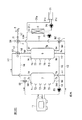
この実施の形態に係る給湯装置1は、図1および図2の様に、熱交換器3と、蛇口等の給湯器5と、給湯用の第1貯湯タンク7と、熱交換用の第2貯湯タンク9と、ヒートポンプ熱源機(加熱手段)11と、温水暖房器19と、ポンプP1〜P3と、調整弁B1〜B4と、第1貯湯タンク7内の湯(高温水)または湯水(水または中低温水)の温度を検出する複数の温度センサT1〜T5と、第2貯湯タンク9内の湯または湯水の温度を検出する複数の温度センサT6〜T10と、外気温を検出する温度センサ(温度検出手段)17と、制御装置27とを備えている。
<First Embodiment>
As shown in FIGS. 1 and 2, a hot
第2貯湯タンク9に貯湯される湯の温度(例えば65℃:第2温度)は、例えば第1貯湯タンク7に貯湯される湯の温度(例えば90℃:第1温度)よりも低く設定される。 The temperature of hot water stored in the second hot water storage tank 9 (for example, 65 ° C .: second temperature) is set lower than the temperature of hot water stored in the first hot water storage tank 7 (for example, 90 ° C .: first temperature). The
第1貯湯タンク7および第2貯湯タンク9はそれぞれ、例えば中空の円柱状に形成されている。第1および第2貯湯タンク7,9の下部(例えば底部)にはそれぞれ、第1および第2貯湯タンク7,9内に給水するための給水口7a,9aが設けられている。各給水口7a,9aはそれぞれ、第1および第2給水管h1,h2を介して、水(例えば水道水)が供給される第3給水管h3に分岐接続されている。
Each of the first hot
また第1および第2貯湯タンク7,9の下部(例えば底部)にそれぞれ吐出口7b,9bが設けられると共に、第1および第2貯湯タンク7,9の上部(例えば天井部)にそれぞれ入湯口7c,9cが設けられている。吐出口7bと入湯口7cは、循環配管h4を介して互いに接続されている。
循環配管h4の一部は、ヒートポンプ熱源機11内に取り込まれている。吐出口9bは、配管h5を介して、循環配管h4においてヒートポンプ熱源機11と吐出口7bとの間の部分に分岐接続されている。以降、循環配管h4と配管h5との分岐接続点を、接続点N1と呼ぶ。入湯口9cは、配管h6を介して、循環配管h4においてヒートポンプ熱源機11と入湯口7cとの間の部分に分岐接続されている。循環配管h4と配管h6との分岐接続点には、3方弁である調整弁(第1弁)B1が配設されている。
A part of the circulation pipe h4 is taken into the heat pump heat source unit 11. The
尚、調整弁B1は、ヒートポンプ熱源機11の加熱により得られる湯の第1および第2貯湯タンク7,9への分配比率を調節するものであり、制御装置27により制御される。
The regulating valve B1 adjusts the distribution ratio of hot water obtained by heating the heat pump heat source unit 11 to the first and second hot
循環配管h4には、例えばヒートポンプ熱源機11と分岐接続点N1との間の部分において、各吐出口7b,9bから吐出される湯水をヒートポンプ熱源機11側に送出するめのポンプP1が配設されている。
The circulation pipe h4 is provided with a pump P1 for sending hot water discharged from the
第1および第2貯湯タンク7,9の上部(例えば天井部)にはそれぞれ、出湯口7d,9dが設けられている。出湯口7dは、第1出湯管h7を介して給湯器5に接続されている。出湯口9dは、第2出湯管h8を介して第1出湯管h7に分岐接続されており、その分岐接続点には、3方弁である調整弁(第3弁)B3が配設されている。
The first and second hot
尚、調整弁B3は、第1および第2貯湯タンク7,9からの各湯の混合比を調整しその調整した湯を給湯器5側に流すものであり、制御装置27により制御される。
The adjusting valve B3 adjusts the mixing ratio of the hot water from the first and second hot
第1出湯管h7において調整弁B3と給湯器5との間の部分には、第3給水管h3の一端部が分岐接続されており、その分岐接続点には、3方弁である調整弁(第4弁)B4が配設されている。 One end portion of the third water supply pipe h3 is branched and connected to a portion between the adjustment valve B3 and the water heater 5 in the first hot water discharge pipe h7, and the adjustment valve that is a three-way valve is connected to the branch connection point. (Fourth valve) B4 is disposed.
尚、調整弁B4は、調整弁B3からの湯と第3給水管h3からの水(または湯水)との混合比を調整しその調整した湯または水を給湯器5側に流すものであり、制御装置27により制御される。
The adjusting valve B4 adjusts the mixing ratio of the hot water from the adjusting valve B3 and the water (or hot water) from the third water supply pipe h3 and flows the adjusted hot water or water to the hot water heater 5 side. It is controlled by the
第2貯湯タンク9の下部(例えば底部)には、吐出口9eが設けられている。吐出口9eは、配管h9を介して第3給水管h3に分岐接続されており、その分岐接続点には、3方弁である調整弁(第2弁)B2が配設されている。
A
尚、調整弁B2は、第2貯湯タンク9の下部からの湯水または第3給水管h3からの水を調整弁B4側に流すものであり、制御装置27により制御される。
The regulating valve B2 is for flowing hot water from the lower part of the second hot
また第2貯湯タンク9には、その上部(例えば天井部)に出湯口9fが設けられると共にその下部(例えば側面の下部)に戻り口9gが設けられている。出湯口9fと戻り口9gとは、循環配管h10を介して接続されている。循環配管h10の一部は、熱交換器3内に引き込まれている。循環配管h10には、例えば熱交換器3と戻り口9gとの間の部分において、出湯口9f側からの湯を戻り口9g側に流すためのポンプP2が配設されている。
The second hot
第1貯湯タンク7の例えば側面には、第1貯湯タンク7内の湯または湯水の温度を検出する複数の温度センサT1〜T5が、第1貯湯タンク7の上部から下部に向かって互いに間隔を空けて配設されている。また第2貯湯タンク9の例えば側面には、第2貯湯タンク9内の湯および湯水の温度を検出する複数の温度センサT6〜T10が、第2貯湯タンク9の上部から下部に向かって互いに間隔を空けて配設されている。
On the side surface of the first hot
温水暖房器19は、例えば、熱交換器3により加熱された暖房用液体を建物内の暖房対象の部屋の床の下側に配設された配管に循環させることで当該床を暖める床暖房器であり、当該床の下側を巡回すると共に熱交換器3内を巡回する様に配設された循環配管19aと、循環配管19a内の暖房用液体を循環させるポンプP3とを備えている。
The
熱交換器3は、循環配管h10に流れる湯と循環配管19aに流れる暖房用液体との間で熱交換を行わせて暖房用液体を加熱する。
The heat exchanger 3 heats the heating liquid by performing heat exchange between the hot water flowing in the circulation pipe h10 and the heating liquid flowing in the
温度センサ17は、例えば建物の外に配設されて当該建物の外の気温を検出する。
The
ヒートポンプ熱源機11は、循環配管h4を加熱することで循環配管h4内の湯水を目標温度に加熱する。ここでは例えば、ヒートポンプ熱源機11の加熱能力が一定に設定されており、ヒートポンプ熱源機11に流入する湯水の流入量がポンプP1により制御されることで、目標温度が制御される。
The heat pump heat source unit 11 heats the hot water in the circulation pipe h4 to a target temperature by heating the circulation pipe h4. Here, for example, the heating capacity of the heat pump
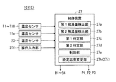
制御装置27は、図2の様に、第1残湯量検出部(残湯量検出手段)27aと、第2残湯量検出部(残湯量検出手段)27bと、第1判定部(判定手段)27cと、第2判定部27dと、制御部(第1および第2制御手段)27eと、操作入力部27fとを備えている。
As shown in FIG. 2, the
第1残湯量検出部27aは、各温度センサT1〜T5の検出温度に基づいて第1貯湯タンク7内に貯湯される湯の量(残湯量)を検出する。例えば、第1残湯量検出部27aは、各温度センサT1〜T3の検出温度が90℃で各温度センサT4〜T5の検出温度が40℃の場合は、第1貯湯タンク7の残湯量は第1貯湯タンク7の天井部から温度センサT3の位置までの量であると検出される。
The first remaining hot water
第2残湯量検出部27bは、第1残湯量検出部27aと同様に、各温度センサT6〜T10の検出結果に基づいて第2貯湯タンク9の残湯量を検出する。
Similar to the first remaining hot water
第1判定部27cは、第1残湯量検出部27aの検出結果に基づいて、第1貯湯タンク7の残湯量が第1起動残湯量以下であるか否か、第1起動残湯量よりも高い値である第1停止残湯量以上であるか否か、および第1起動残湯量よりも低い値である所定量(第1所定量)以下であるか否かを判定する。
Based on the detection result of the first remaining hot water
第2判定部27dは、第2残湯量検出部27bの検出結果に基づいて、第2貯湯タンク9の残湯量が第2起動残湯量以下であるか否か、第2起動残湯量よりも高い値である第2停止残湯量以上であるか否か、および第2貯湯タンク9内の湯水の量(第2貯湯タンク9の容量から第2貯湯タンク9の残湯量を引いた量)が所定量(第2所定量)以上であるか否かを判定する。
Based on the detection result of the second remaining hot water
制御部27eは、第1および第2判定部27c,27dの判定結果等に基づいてヒートポンプ熱源器11、ポンプP1および調整弁B1を制御する。より詳細には、制御部27eは、第1判定部27cの判定の結果、第1貯湯タンク7の残湯量が第1起動残湯量以下である場合は、ヒートポンプ熱源機11、ポンプP1および調整弁B1を制御して第1貯湯タンク7内の湯水を加熱し、また第1貯湯タンク7の残湯量が第1停止残湯量以上である場合は、ヒートポンプ熱源機11およびポンプP1を停止させて第1貯湯タンク7内の湯水の加熱を止める。また制御部27eは、第2判定部27dの判定の結果、第2貯湯タンク7の残湯量が第2起動残湯量以下である場合は、ヒートポンプ熱源機11、ポンプP1および調整弁B1を制御して第2貯湯タンク9内の湯水(水または中低温水)を加熱し、また第2貯湯タンク7の残湯量が第2停止残湯量以上である場合は、ヒートポンプ熱源機11およびポンプP1を停止させて第2貯湯タンク9内の湯水の加熱を止める。
The
更により詳細には、制御部27eは、第1貯湯タンク7内の湯水を加熱する際は、(a1)ヒートポンプ熱源機11を所定の加熱能力で稼働させ、且つ(b1)ポンプP1をヒートポンプ熱源機11から出湯する湯が第1貯湯タンク7に貯湯される湯の設定温度となる様に所要の排出量で稼働させ、且つ(c1)調整弁B1を第1貯湯タンク7側を全開にし第2貯湯タンク9側を全閉にする。上記(b1)では例えば、循環配管h4にヒートポンプ熱源機11から出湯する湯の温度を検出する温度センサ11aが配設されており、制御部27eは、温度センサ11aの検出温度が第1貯湯タンク7内の湯の設定温度になる様にポンプP1の排出量を制御する。上記(c1)により、第1および第2貯湯タンク7,9のうち、第1貯湯タンク7内の湯水だけが7b→P1→11→B1→7cの順に流れてヒートポンプ熱源機11により加熱される。
More specifically, when the
また制御部27eは、第2貯湯タンク7内の湯水を加熱する際は、(a2)ヒートポンプ熱源機11を所定の加熱能力で稼働させ、且つ(b2)ポンプP1をヒートポンプ熱源機11から出湯する湯が第2貯湯タンク7に貯湯される湯の設定温度となる様に所要の排出量で稼働させ、且つ(c2)調整弁B1を第1貯湯タンク7側を全閉にし第2貯湯タンク9側を全開にする。上記(b2)では例えば、制御部27eは、温度センサ11aの検出温度が第2貯湯タンク7の設定温度になる様にポンプP1の排出量を制御する。上記(c2)により、第1および第2貯湯タンク7,9のうち、第2貯湯タンク7内の湯水だけが9b→P1→11→B1→9cの順に流れてヒートポンプ熱源機11により加熱される。
When the hot water in the second hot
尚、制御部27eは、第1貯湯タンク7内の湯水を加熱する場合と第2貯湯タンク9内の湯水を加熱する場合とが同時に起こった場合は、先に一方の加熱(例えば第1貯湯タンク7内の湯水の加熱)を行い、その加熱の終了後に他方の加熱を行うか、または、ヒートポンプ熱源機11から出湯する湯の温度が第1および第2貯湯タンク7,9に貯湯される湯の各設定温度のうちの高い方の設定温度(ここでは第1貯湯タンクに貯湯される湯の設定温度)となる様にポンプP1の排出量を制御すると共に、調整弁B1をヒートポンプ熱源機11からの湯が第1および第2貯湯タンク7,9の両方に入湯する様に調整弁B1を制御することで、高い方の設定温度に合わせて第1および第2貯湯タンク内の湯水を同時に加熱する。
In addition, when the case where the hot water in the 1st hot
また制御部27eは、第1判定部27cの判定結果に基づいて調整弁B3を制御する。より詳細には、制御部27eは、第1貯湯タンク7の残湯量が第1所定量(所定量)より多い場合は、調整弁B3を第1貯湯タンク7側を全開とし第2貯湯タンク9側を全閉とする様に制御し、他方、第1貯湯タンク7の残湯量が第1所定量以下の場合は、調整弁B3を第1貯湯タンク7側を全閉とし第2貯湯タンク9側を全開とする様に制御する(尚、調整弁B3を、第1貯湯タンク7側を全閉とし第2貯湯タンク9側を全開とする様に制御する代わりに、第1貯湯タンク7からの湯と第2貯湯タンク9からの湯とが所定の混合比で混合する様に制御してもよい)。これにより、第1貯湯タンク7の残湯量が第1所定量以下の場合(即ち第1貯湯タンク7が湯切れしそうな場合)は、第2貯湯タンク9内の湯が使用されて第1貯湯タンク7の湯切れが防止される。
The
また制御部27eは、操作入力部27fに設定入力された給湯温度に基づいて調整弁B4を制御する。より詳細には、例えば第1出湯管h7における調整弁B4と給湯器5との間の部分には、当該部分に流れる湯または湯水の温度を検出する温度センサ21が配設されており、制御部27eは、温度センサ21の検出温度が操作入力部27fに設定入力された給湯温度になる様に調整弁B4を制御する。これにより給湯器5から出湯する湯の温度が給湯温度に制御される。
The
また制御部27eは、第2判定部27dの判定結果に基づいて調整弁B2を制御する。より詳細には、制御部27eは、第2判定部27dの判定の結果、第2貯湯タンク9内の湯水の量が第2所定量(所定量)以上である場合は、調整弁B2を第2貯湯タンク9側を全開とし水道水の流入側Iを全閉となる様に制御し、他方、第2貯湯タンク9内の湯水の量が第2所定量以上でない場合は、調整弁B2を第2貯湯タンク9側を全閉とし水道水の流入側Iを全開となる様に制御する(尚、第2貯湯タンク9内の湯水の量が第2所定量以上である場合では、調整弁B2を、第2貯湯タンク9側を全閉とし水道水の流入側Iを全開となる様に制御する代わりに、第2貯湯タンク9からの湯水とI側からの水道水とが所定の混合比で混合する様に制御してもよい)。
The
これにより、給湯器5から湯(第1貯湯タンク7に貯湯される湯の設定温度よりも低い温度の湯)が出湯されると、第2貯湯タンク9の下部の湯水が9e→B2→B4の順に流れて調整弁B4において調整弁B3からの湯と混合されて給湯器5から出湯される(即ち第2貯湯タンク9の下部に貯まった湯水が給湯器5からの給湯に使用される)。そして、この出湯により第2貯湯タンク9内の下部の湯水が減少した分、第2貯湯タンク9の下部には、給水口9aから供給水(水道水)が供給される。これにより、第2貯湯タンク9内の下部には、中低温の湯(即ち後述の様に熱交換器3から戻される湯)が溜まり難くなって給水口9aからの供給水が溜まり易くなり、第2貯湯タンク9の湯水の加熱時にヒートポンプ熱源器11の加熱効率の低下が防止される。
Thus, when hot water (hot water having a temperature lower than the set temperature of hot water stored in the first hot water storage tank 7) is discharged from the hot water heater 5, the hot water in the lower part of the second hot
尚、第2貯湯タンク9内の湯が9d→B3→B4→5の順に流れて給湯器5から出湯した場合も、その出湯により第2貯湯タンク9内の湯が減少した分、給水口9aから第2貯湯タンク9内に供給水が供給される。同様に、第1貯湯タンク7内の湯が7d→B3→B4→5の順に流れて給湯器5から出湯した場合も、その出湯により第1貯湯タンク7内の湯が減少した分、給水口7aから第1貯湯タンク7内に供給水が供給される。
Even when the hot water in the second hot
また制御部27eは、操作入力部27fに暖房開始の指示が入力されると、操作入力部27fに設定入力された暖房温度に基づいて温水暖房器19およびポンプP2を稼働させる。即ち、例えば循環配管19aにおける熱交換器3の出湯口側にはその出湯口から出湯する湯の温度を検出する温度センサ23が配設されており、制御部27eは、操作入力部27fに暖房開始の指示が入力されると、ポンプP2を所定の排水量で稼働させると共に温度センサ23の検出温度が暖房温度になる様にポンプP3の排出量を制御する。
Moreover, if the instruction | indication of a heating start is input into the
これにより、ポンプP2により第2貯湯タンク9内の湯が9f→3→P2→9gの順に循環配管h10を循環させられると共に、ポンプP3により循環配管19a内の暖房用液体が循環配管19aを循環させられる。そして熱交換器3において循環配管h10内の湯により循環配管19a内の暖房用液体が暖房温度に加熱され、この暖房用液体により暖房対象の部屋の床が暖められる。尚、操作入力部27fに暖房停止の指示が入力されると、各ポンプP2,P3が停止されて暖房が停止される。
Thus, the hot water in the second hot
以上の様に構成された給湯装置によれば、給湯用の第1貯湯タンク7と熱交換用の第2貯湯タンク9とが別々に設けられるので、第1貯湯タンク7において給湯用の湯を確保でき、給湯時の湯切れを防止できる。
According to the hot water supply apparatus configured as described above, since the first hot
また第2貯湯タンク9には、第1貯湯タンク7内の湯の温度よりも低い温度の湯が貯湯されるので、第2貯湯タンク9内の湯からの放熱損失を低減できる。
Also in the second hot
また制御部27eにより、ヒートポンプ熱源器11から出湯される湯の温度が第1温度(第1貯湯タンク7に貯湯される湯の温度)と第2温度(第2貯湯タンク9に貯湯される湯の温度)とに制御されるので、1つのヒートポンプ熱源器11で第1温度と第2温度との異なる温度の湯を供給できる。
Moreover, the temperature of the hot water discharged from the heat pump heat source device 11 by the
また第2貯湯タンク9の下部に貯まった湯水を給湯器5からの給湯に使用するので、第2貯湯タンク9の湯水の加熱時において、第2貯湯タンク9の下部に貯まった湯水がヒートポンプ熱源器11に吐出されて加熱される事を防止でき、これによりヒートポンプ熱源器11の加熱効率の低下を防止できる。
Moreover, since the hot water stored in the lower part of the second hot
また第2貯湯タンク9に貯湯された湯を給湯器5からの給湯に使用するので、給湯時の湯切れを防止できる。特に第1貯湯タンク7の残湯量が第1所定量以下の場合に、第2貯湯タンク9内の湯を給湯器5からの給湯に使用するので、効果的に給湯の湯切れを防止できる。
Moreover, since the hot water stored in the second hot
尚、この実施形態では、ヒートポンプ熱源器11の加熱能力を一定にして、制御部27’eによりポンプP1の排出量を制御することで、ヒートポンプ熱源器11から出湯する湯の温度を第1温度または第2温度に制御する場合で説明したが、ポンプP1の排出量を一定にして、制御部27’eによりヒートポンプ熱源器11の加熱能力を制御することで、ヒートポンプ熱源器11から出湯する湯の温度を第1温度または第2温度に制御してもよい。 In this embodiment, the temperature of the hot water discharged from the heat pump heat source 11 is set to the first temperature by making the heating capacity of the heat pump heat source 11 constant and controlling the discharge amount of the pump P1 by the control unit 27'e. Alternatively, as described in the case of controlling to the second temperature, the hot water discharged from the heat pump heat source device 11 is controlled by controlling the heating capacity of the heat pump heat source device 11 by the control unit 27'e while keeping the discharge amount of the pump P1 constant. The temperature may be controlled to the first temperature or the second temperature.
尚、この実施形態では、第2貯湯タンク9に貯湯される湯の温度(第2温度)が第1貯湯タンク7に貯湯される湯の温度(第1温度)よりも低く設定される場合で説明したが、第1温度が第2温度よりも低く設定されてもよい。この場合は、第1貯湯タンク7には、第2貯湯タンク9内の湯の温度よりも低い温度の湯が貯湯されるので、第1貯湯タンク7内の湯からの放熱損失を低減できる。尚、第1温度と第2温度を同じ温度に設定してもよい。
In this embodiment, the temperature of the hot water stored in the second hot water storage tank 9 (second temperature) is set lower than the temperature of the hot water stored in the first hot water storage tank 7 (first temperature). Although demonstrated, 1st temperature may be set lower than 2nd temperature. In this case, hot water having a temperature lower than the temperature of the hot water in the second hot
<第2実施形態>
この実施形態に係る給湯装置1Bは、図3の様に、第1実施形態(図2参照)において更に、外気温を検出する温度センサ(温度検出手段)17と、温度センサ17の検出温度に基づいて第2貯湯タンク9に貯湯される湯の温度(第2温度)の設定温度を変更する設定温度変更部(設定温度変更手段)27gとを更に備えたものである。
Second Embodiment
As shown in FIG. 3, the hot
設定温度変更部27gは、例えば、第2貯湯タンク9に貯湯される湯の設定温度を、前記検出温度が基準温度(例えば14℃)よりも低いほど、より高くなる様に変更し、または前記検出温度が前記基準温度よりも高いほどより低くなる様に変更する。
For example, the set
この様に構成された給湯装置1Bによれば、第2貯湯タンク9に貯湯される湯の設定温度を外気温に応じて変更するので、第2貯湯タンク9の蓄熱量を外気温に応じて最適な量に調整して確保でき、第2貯湯タンク9からの放熱損失を低減できる。
According to the hot
尚ここでは、第2貯湯タンク9に貯湯される湯の設定温度を変更する場合で説明したが、更に/または、第1貯湯タンク7に貯湯される湯の設定温度を変更してもよい。これにより第1貯湯タンク7の蓄熱量を外気温に応じて最適な量に調整して確保でき、第1貯湯タンク7からの放熱損失を低減できる。
Here, the case where the set temperature of hot water stored in the second hot
<第3実施形態>
この実施形態に係る給湯装置1Cは、図4の様に、第1実施形態(図2参照)において更に、操作入力部27fに設定入力された暖房温度に応じて第2貯湯タンク9に貯湯される湯の設定温度を変更する設定温度変更部(設定温度変更手段)27hを更に備えたものである。
<Third Embodiment>
As shown in FIG. 4, the hot
設定温度変更部27hは、例えば、第2貯湯タンク9に貯湯される湯の設定温度を、操作入力部27fに設定入力された暖房温度と同じ温度、またはその暖房温度よりも所定温度高い温度に変更する。
The set
この様に構成された給湯装置1Cによれば、第2貯湯タンク9に貯湯される湯の設定温を暖房温度に応じて変更するので、第2貯湯タンク9の蓄熱量を暖房温度に応じて最適な量に調整して確保できる。
According to the thus constructed
<第4実施形態>
この実施形態に係る給湯装置1Dは、図5の様に、第1実施形態(図1参照)において、熱交換器3を暖房に使用する代わりに浴槽31の追焚または保温に使用したものである。この給湯装置1Dは、図5の様に、第1実施形態において、温水暖房器19の代わりに、浴槽31と、循環配管31aと、ポンプP4とを備えて構成される。以下、第1実施形態と同じ部分は同一符号を付して説明を省略して異なる部分だけ説明する。
<Fourth embodiment>
As shown in FIG. 5, the hot
循環配管31aは、浴槽31内の湯水を熱交換器3内に循環させるものであり、その一端が浴槽31の吐出口31cに接続され、その他端が浴槽31の出湯口31dに接続されており、その途中の部分が熱交換器3内に引き込まれている。従ってこの実施形態では、熱交換器3は、循環配管h10内の湯と循環配管31a内の湯水との間で熱交換を行う。
The
ポンプP4は、浴槽31内の湯水を循環配管31aに循環させるものであり、循環配管31aにおける例えば熱交換器3と吐出口31cとの間の部分に配設されている。
The pump P4 circulates hot water in the
この実施形態の制御部27j(図2参照)は、第1実施形態の制御部27eにおいて、ポンプP3(図1参照)を制御する代わりにポンプP4を制御する機能を有する。より詳細には、制御部27jは、操作入力部27fに追焚開始または保温開始の指示が入力されると、操作入力部27fに設定入力された追焚温度または保温温度(目標温度)に基づいて各ポンプP2,P4を稼働させる。即ち、例えば循環配管31aにおける熱交換器3の出湯口側にはその出湯口から出湯される湯の温度を検出する温度センサ31eが配設されており、制御部27jは、操作入力部27fに追焚開始または保温開始の指示が入力されると、ポンプP2を所定の排水量で稼働させると共に温度センサ31eの検出温度が前記追焚温度または保温温度になる様にポンプP4の排出量を制御する。
The
これにより、ポンプP2により第2貯湯タンク9内の湯が9f→3→P2→9gの順に循環配管h10を循環すると共にポンプP4により浴槽31内の湯水が循環配管31aを循環し、熱交換器3において循環配管h10内の湯により循環配管31a内の湯水が追焚温度または保温温度に加熱されて、浴槽31内の湯水が追焚または保温される。尚、操作入力部27fに追焚停止または保温停止の指示が入力されると、各ポンプP2,P4が停止されて追焚または保温が止められる。
As a result, the hot water in the second hot
この様に構成された給湯装置1Dによれば、熱交換器3を浴槽31内の湯水の追焚または保温に使用する場合にも、第1実施形態と同様の効果を得る事ができる。
According to the hot
<第5実施形態>
この実施形態に係る給湯装置1Eは、図4の様に、第4実施形態(図2参照)において更に、操作入力部27fに設定入力された追焚温度または保温温度(以後、これらの温度を目標温度と呼ぶ)に基づいて第2貯湯タンク7に貯湯される湯の設定温度を変更する設定温度変更部(設定温度変更手段)27iを更に備えたものである。
<Fifth Embodiment>
As shown in FIG. 4, the hot
設定温度変更部27iは、例えば、第2貯湯タンク9に貯湯される湯の設定温度を、操作入力部27fに設定入力された目標温度と同じ温度、またはその目標温度よりも所定温度高い温度に変更する。
The set
この様に構成された給湯装置1Eによれば、第2貯湯タンク9に貯湯される湯の設定温を操作入力部27fに設定入力された目標温度に応じて変更するので、第2貯湯タンク9の蓄熱量を当該目標温度に応じて最適な量に調整して確保できる。
According to the hot
尚、説明は省略するが第1〜第5実施形態の組み合わせを考えてもよい。 In addition, although description is abbreviate | omitted, you may consider the combination of 1st-5th embodiment.
1,1B,1C,1D 給湯装置
3 熱交換器
5 給湯器
7 第1貯湯タンク
9 第2貯湯タンク
11 ヒートポンプ熱源機
19 温水暖房器
21 温度センサ
27 制御装置
27a 第1残湯量検出部
27b 第2残湯量検出部
27c 第1判定部
27d 第2判定部
27e,27j 制御部
27f 操作入力部
27g,27h,27i 設定温度変更部
P1〜P3 ポンプ
B1,B2,B3,B4 調整弁
DESCRIPTION OF
Claims (6)
第1温度の湯が貯湯され、その湯が所定の給湯器(5)から出湯される給湯用の第1貯湯タンク(7)と、
第2温度の湯が貯湯され、その湯が前記熱交換器に循環されて前記熱交換器を加熱する熱交換用の第2貯湯タンク(9)と、
前記第1貯湯タンク(7)および前記第2貯湯タンク(9)の湯水を加熱する加熱手段(11)と、
前記加熱手段から出湯される湯の温度を前記第1温度または前記第2温度に制御する第1制御手段(27e,27j)と、
前記加熱手段から出湯される前記第1温度の湯の前記第1貯湯タンクへの入湯と、前記加熱手段から出湯される前記第2温度の湯の前記第2貯湯タンクへの入湯とを切り換える第1弁(B1)と、
前記第1貯湯タンク(7)の上部から出湯される湯と前記第2貯湯タンク(9)の下部から排出される湯水とを混合し又は選択的に前記所定の給湯器(5)から排出する第2弁(B2)を備え、
前記第1温度と前記第2温度とが異なことを特徴とする給湯装置。 A heat exchanger (3);
A first hot water storage tank (7) for hot water supply in which hot water of a first temperature is stored and the hot water is discharged from a predetermined water heater (5);
A second hot water storage tank (9) for heat exchange in which hot water at a second temperature is stored, and the hot water is circulated through the heat exchanger to heat the heat exchanger;
Heating means (11) for heating hot water in the first hot water storage tank (7) and the second hot water storage tank (9);
First control means (27e, 27j) for controlling the temperature of hot water discharged from the heating means to the first temperature or the second temperature;
Switching between hot water entering the first hot water storage tank of the first temperature hot water discharged from the heating means and hot water entering the second hot water storage tank of the second temperature hot water discharged from the heating means is performed. 1 valve (B1) ,
Hot water discharged from the upper part of the first hot water storage tank (7) and hot water discharged from the lower part of the second hot water storage tank (9) are mixed or selectively discharged from the predetermined hot water heater (5). A second valve (B2) ,
The hot water supply apparatus, wherein the first temperature and the second temperature are different.
前記第2温度は前記第1温度よりも低いことを特徴とする給湯装置。 The hot water supply device according to claim 1,
The hot water supply apparatus, wherein the second temperature is lower than the first temperature.
前記第1温度は前記第2温度よりも低いことを特徴とする給湯装置。 The hot water supply device according to claim 1,
The hot water supply apparatus, wherein the first temperature is lower than the second temperature.
第1温度の湯が貯湯され、その湯が所定の給湯器(5)から出湯される給湯用の第1貯湯タンク(7)と、
第2温度の湯が貯湯され、その湯が前記熱交換器に循環されて前記熱交換器を加熱する熱交換用の第2貯湯タンク(9)と、
前記第1貯湯タンク(7)および前記第2貯湯タンク(9)の湯水を加熱する加熱手段(11)と、
前記加熱手段から出湯される湯の温度を前記第1温度または前記第2温度に制御する第1制御手段(27e,27j)と、
前記加熱手段から出湯される前記第1温度の湯の前記第1貯湯タンクへの入湯と、前記加熱手段から出湯される前記第2温度の湯の前記第2貯湯タンクへの入湯とを切り換える第1弁(B1)と
を備え、
前記第1温度と前記第2温度とが異なり、
外気温を検出する温度検出手段(17)と、
前記温度検出手段により検出された温度に応じて前記第1温度および/または前記第2温度の設定温度を変更する設定温度変更手段(27g)と、
前記第1貯湯タンク(7)の上部から出湯される湯と前記第2貯湯タンク(9)の上部から排出される湯水とを混合し前記所定の給湯器(5)から出湯する第3弁(B3)と
を更に備えることを特徴とする給湯装置。 A heat exchanger (3);
A first hot water storage tank (7) for hot water supply in which hot water of a first temperature is stored and the hot water is discharged from a predetermined water heater (5);
A second hot water storage tank (9) for heat exchange in which hot water at a second temperature is stored, and the hot water is circulated through the heat exchanger to heat the heat exchanger;
Heating means (11) for heating hot water in the first hot water storage tank (7) and the second hot water storage tank (9);
First control means (27e, 27j) for controlling the temperature of hot water discharged from the heating means to the first temperature or the second temperature;
Switching between hot water entering the first hot water storage tank of the first temperature hot water discharged from the heating means and hot water entering the second hot water storage tank of the second temperature hot water discharged from the heating means is performed. With 1 valve (B1)
With
The first temperature is different from the second temperature,
Temperature detection means (17) for detecting the outside air temperature;
Set temperature changing means (27g) for changing the set temperature of the first temperature and / or the second temperature according to the temperature detected by the temperature detecting means;
A third valve for mixing hot water discharged from the upper part of the first hot water storage tank (7) and hot water discharged from the upper part of the second hot water storage tank (9) and discharging the hot water from the predetermined hot water heater (5) ( A hot water supply apparatus, further comprising: B3) .
第1温度の湯が貯湯され、その湯が所定の給湯器(5)から出湯される給湯用の第1貯湯タンク(7)と、
第2温度の湯が貯湯され、その湯が前記熱交換器に循環されて前記熱交換器を加熱する熱交換用の第2貯湯タンク(9)と、
前記第1貯湯タンク(7)および前記第2貯湯タンク(9)の湯水を加熱する加熱手段(11)と、
前記加熱手段から出湯される湯の温度を前記第1温度または前記第2温度に制御する第1制御手段(27e,27j)と、
前記加熱手段から出湯される前記第1温度の湯の前記第1貯湯タンクへの入湯と、前記加熱手段から出湯される前記第2温度の湯の前記第2貯湯タンクへの入湯とを切り換える第1弁(B1)と、
前記第1貯湯タンク(7)の上部から出湯される湯と前記第2貯湯タンク(9)の上部から排出される湯水とを混合し前記所定の給湯器(5)から出湯する第3弁(B3)と
を備え、
前記第1温度と前記第2温度とが異なり、
前記熱交換器(3)において前記第2貯湯タンク(9)から循環される前記第2温度の湯と所定の温水暖房器(19)から循環される暖房用液体との間で熱交換が行われる場合において、
前記所定の温水暖房器に設定された暖房温度に基づいて前記第2温度の設定温度を変更する設定温度変更手段(27h)
を更に備えることを特徴とする給湯装置。 A heat exchanger (3);
A first hot water storage tank (7) for hot water supply in which hot water of a first temperature is stored and the hot water is discharged from a predetermined water heater (5);
A second hot water storage tank (9) for heat exchange in which hot water at a second temperature is stored, and the hot water is circulated through the heat exchanger to heat the heat exchanger;
Heating means (11) for heating hot water in the first hot water storage tank (7) and the second hot water storage tank (9);
First control means (27e, 27j) for controlling the temperature of hot water discharged from the heating means to the first temperature or the second temperature;
Switching between hot water entering the first hot water storage tank of the first temperature hot water discharged from the heating means and hot water entering the second hot water storage tank of the second temperature hot water discharged from the heating means is performed. 1 valve (B1),
A third valve for mixing hot water discharged from the upper part of the first hot water storage tank (7) and hot water discharged from the upper part of the second hot water storage tank (9) and discharging the hot water from the predetermined hot water heater (5) ( B3) and
With
The first temperature is different from the second temperature,
In the heat exchanger (3), heat exchange is performed between the second temperature hot water circulated from the second hot water storage tank (9) and the heating liquid circulated from a predetermined hot water heater (19). In the case where
Setting temperature changing means (27h) for changing the setting temperature of the second temperature based on the heating temperature set in the predetermined hot water heater
A hot water supply apparatus further comprising:
第1温度の湯が貯湯され、その湯が所定の給湯器(5)から出湯される給湯用の第1貯湯タンク(7)と、
第2温度の湯が貯湯され、その湯が前記熱交換器に循環されて前記熱交換器を加熱する熱交換用の第2貯湯タンク(9)と、
前記第1貯湯タンク(7)および前記第2貯湯タンク(9)の湯水を加熱する加熱手段(11)と、
前記加熱手段から出湯される湯の温度を前記第1温度または前記第2温度に制御する第1制御手段(27e,27j)と、
前記加熱手段から出湯される前記第1温度の湯の前記第1貯湯タンクへの入湯と、前記加熱手段から出湯される前記第2温度の湯の前記第2貯湯タンクへの入湯とを切り換える第1弁(B1)と、
前記第1貯湯タンク(7)の上部から出湯される湯と前記第2貯湯タンク(9)の上部から排出される湯水とを混合し前記所定の給湯器(5)から出湯する第3弁(B3)と
を備え、
前記第1温度と前記第2温度とが異なり、
前記熱交換器(3)において前記第2貯湯タンク(9)から循環される前記第2温度の湯と所定の浴槽(31)から循環される湯水との間で熱交換が行われる場合において、
前記所定の浴槽内の前記湯水の目標温度が設定入力される所定の操作入力手段(27f)に設定入力された前記目標温度に基づいて前記第2温度の設定温度を変更する設定温度変更手段(27i)を更に備えることを特徴とする給湯装置。 A heat exchanger (3);
A first hot water storage tank (7) for hot water supply in which hot water of a first temperature is stored and the hot water is discharged from a predetermined water heater (5);
A second hot water storage tank (9) for heat exchange in which hot water at a second temperature is stored, and the hot water is circulated through the heat exchanger to heat the heat exchanger;
Heating means (11) for heating hot water in the first hot water storage tank (7) and the second hot water storage tank (9);
First control means (27e, 27j) for controlling the temperature of hot water discharged from the heating means to the first temperature or the second temperature;
Switching between hot water entering the first hot water storage tank of the first temperature hot water discharged from the heating means and hot water entering the second hot water storage tank of the second temperature hot water discharged from the heating means is performed. 1 valve (B1),
A third valve for mixing hot water discharged from the upper part of the first hot water storage tank (7) and hot water discharged from the upper part of the second hot water storage tank (9) and discharging the hot water from the predetermined hot water heater (5) ( B3) and
With
The first temperature is different from the second temperature,
In the case where heat exchange is performed between the second temperature hot water circulated from the second hot water storage tank (9) and the hot water circulated from a predetermined bathtub (31) in the heat exchanger (3),
Setting temperature changing means for changing the set temperature of the second temperature based on the target temperature set and inputted to a predetermined operation input means (27f) to which the target temperature of the hot water in the predetermined bathtub is set and inputted. 27i) is further provided.
Priority Applications (1)
| Application Number | Priority Date | Filing Date | Title |
|---|---|---|---|
| JP2010087638A JP5742108B2 (en) | 2010-04-06 | 2010-04-06 | Water heater |
Applications Claiming Priority (1)
| Application Number | Priority Date | Filing Date | Title |
|---|---|---|---|
| JP2010087638A JP5742108B2 (en) | 2010-04-06 | 2010-04-06 | Water heater |
Publications (3)
| Publication Number | Publication Date |
|---|---|
| JP2011220560A JP2011220560A (en) | 2011-11-04 |
| JP2011220560A5 JP2011220560A5 (en) | 2013-05-02 |
| JP5742108B2 true JP5742108B2 (en) | 2015-07-01 |
Family
ID=45037773
Family Applications (1)
| Application Number | Title | Priority Date | Filing Date |
|---|---|---|---|
| JP2010087638A Active JP5742108B2 (en) | 2010-04-06 | 2010-04-06 | Water heater |
Country Status (1)
| Country | Link |
|---|---|
| JP (1) | JP5742108B2 (en) |
Families Citing this family (10)
| Publication number | Priority date | Publication date | Assignee | Title |
|---|---|---|---|---|
| US20140202549A1 (en) * | 2013-01-23 | 2014-07-24 | Honeywell International Inc. | Multi-tank water heater systems |
| US9885484B2 (en) | 2013-01-23 | 2018-02-06 | Honeywell International Inc. | Multi-tank water heater systems |
| US10670302B2 (en) | 2014-03-25 | 2020-06-02 | Ademco Inc. | Pilot light control for an appliance |
| US20150277463A1 (en) | 2014-03-25 | 2015-10-01 | Honeywell International Inc. | System for communication, optimization and demand control for an appliance |
| US9799201B2 (en) | 2015-03-05 | 2017-10-24 | Honeywell International Inc. | Water heater leak detection system |
| US9920930B2 (en) | 2015-04-17 | 2018-03-20 | Honeywell International Inc. | Thermopile assembly with heat sink |
| US10132510B2 (en) | 2015-12-09 | 2018-11-20 | Honeywell International Inc. | System and approach for water heater comfort and efficiency improvement |
| CN106322752B (en) * | 2016-09-07 | 2019-04-12 | 中国北方车辆研究所 | A kind of parallel electric water heater with dual inner containers and its heating means |
| US10119726B2 (en) | 2016-10-06 | 2018-11-06 | Honeywell International Inc. | Water heater status monitoring system |
| US10969143B2 (en) | 2019-06-06 | 2021-04-06 | Ademco Inc. | Method for detecting a non-closing water heater main gas valve |
Family Cites Families (6)
| Publication number | Priority date | Publication date | Assignee | Title |
|---|---|---|---|---|
| JP3906700B2 (en) * | 2002-01-31 | 2007-04-18 | 株式会社デンソー | Heat pump type water heater |
| JP4375095B2 (en) * | 2004-04-19 | 2009-12-02 | パナソニック株式会社 | Heat pump water heater |
| JP2006336937A (en) * | 2005-06-01 | 2006-12-14 | Denso Corp | Storage type hot water supply device |
| JP2007225205A (en) * | 2006-02-24 | 2007-09-06 | Noritz Corp | Hot water supply system |
| JP4843382B2 (en) * | 2006-05-31 | 2011-12-21 | 東芝キヤリア株式会社 | Heat pump water heater |
| JP2008076014A (en) * | 2006-09-25 | 2008-04-03 | Noritz Corp | Storable heat source device and storable heat source system |
-
2010
- 2010-04-06 JP JP2010087638A patent/JP5742108B2/en active Active
Also Published As
| Publication number | Publication date |
|---|---|
| JP2011220560A (en) | 2011-11-04 |
Similar Documents
| Publication | Publication Date | Title |
|---|---|---|
| JP5742108B2 (en) | Water heater | |
| JP2011220560A5 (en) | ||
| JP5577135B2 (en) | Water heater | |
| JP2008145096A (en) | Hot water supply system and hot water supply method | |
| JP5436933B2 (en) | Hot water system | |
| JP2007032904A (en) | Cogeneration system | |
| JP5401116B2 (en) | Water heater | |
| JP2008039340A (en) | Hot water supply device | |
| JP5401117B2 (en) | Water heater | |
| JP5358883B2 (en) | Water heater | |
| JP2007003057A (en) | Storage water heater | |
| JP5533553B2 (en) | Hot water storage water heater | |
| JP2011112238A (en) | Storage type hot water supply system | |
| JP4165594B2 (en) | Hot water storage water heater | |
| JP6147541B2 (en) | Heat source equipment | |
| JP6197452B2 (en) | Hot water system | |
| JP6143092B2 (en) | Hot water storage system | |
| JP2004100997A (en) | Hot-water supply heating system | |
| JP5577225B2 (en) | Water heater | |
| JP5671304B2 (en) | Heat source equipment | |
| JP2008170101A (en) | Storage type hot water supply system | |
| JP6403631B2 (en) | Hot water storage unit | |
| JP6403630B2 (en) | Hot water storage unit | |
| JP4155162B2 (en) | Hot water storage water heater | |
| JP2008128527A (en) | Hot water supply system and method |
Legal Events
| Date | Code | Title | Description |
|---|---|---|---|
| A521 | Written amendment |
Free format text: JAPANESE INTERMEDIATE CODE: A523 Effective date: 20130312 |
|
| A621 | Written request for application examination |
Free format text: JAPANESE INTERMEDIATE CODE: A621 Effective date: 20130313 |
|
| A977 | Report on retrieval |
Free format text: JAPANESE INTERMEDIATE CODE: A971007 Effective date: 20140129 |
|
| A131 | Notification of reasons for refusal |
Free format text: JAPANESE INTERMEDIATE CODE: A131 Effective date: 20140212 |
|
| A521 | Written amendment |
Free format text: JAPANESE INTERMEDIATE CODE: A523 Effective date: 20140409 |
|
| A131 | Notification of reasons for refusal |
Free format text: JAPANESE INTERMEDIATE CODE: A131 Effective date: 20140930 |
|
| A521 | Written amendment |
Free format text: JAPANESE INTERMEDIATE CODE: A523 Effective date: 20141127 |
|
| TRDD | Decision of grant or rejection written | ||
| A01 | Written decision to grant a patent or to grant a registration (utility model) |
Free format text: JAPANESE INTERMEDIATE CODE: A01 Effective date: 20150407 |
|
| A61 | First payment of annual fees (during grant procedure) |
Free format text: JAPANESE INTERMEDIATE CODE: A61 Effective date: 20150420 |
|
| R151 | Written notification of patent or utility model registration |
Ref document number: 5742108 Country of ref document: JP Free format text: JAPANESE INTERMEDIATE CODE: R151 |