JP5740857B2 - Ball type constant velocity joint - Google Patents
Ball type constant velocity joint Download PDFInfo
- Publication number
- JP5740857B2 JP5740857B2 JP2010154645A JP2010154645A JP5740857B2 JP 5740857 B2 JP5740857 B2 JP 5740857B2 JP 2010154645 A JP2010154645 A JP 2010154645A JP 2010154645 A JP2010154645 A JP 2010154645A JP 5740857 B2 JP5740857 B2 JP 5740857B2
- Authority
- JP
- Japan
- Prior art keywords
- inner ring
- ball
- groove
- axial
- axial direction
- Prior art date
- Legal status (The legal status is an assumption and is not a legal conclusion. Google has not performed a legal analysis and makes no representation as to the accuracy of the status listed.)
- Active
Links
Images

Classifications
-
- F—MECHANICAL ENGINEERING; LIGHTING; HEATING; WEAPONS; BLASTING
- F16—ENGINEERING ELEMENTS AND UNITS; GENERAL MEASURES FOR PRODUCING AND MAINTAINING EFFECTIVE FUNCTIONING OF MACHINES OR INSTALLATIONS; THERMAL INSULATION IN GENERAL
- F16D—COUPLINGS FOR TRANSMITTING ROTATION; CLUTCHES; BRAKES
- F16D3/00—Yielding couplings, i.e. with means permitting movement between the connected parts during the drive
- F16D3/16—Universal joints in which flexibility is produced by means of pivots or sliding or rolling connecting parts
- F16D3/20—Universal joints in which flexibility is produced by means of pivots or sliding or rolling connecting parts one coupling part entering a sleeve of the other coupling part and connected thereto by sliding or rolling members
- F16D3/22—Universal joints in which flexibility is produced by means of pivots or sliding or rolling connecting parts one coupling part entering a sleeve of the other coupling part and connected thereto by sliding or rolling members the rolling members being balls, rollers, or the like, guided in grooves or sockets in both coupling parts
- F16D3/223—Universal joints in which flexibility is produced by means of pivots or sliding or rolling connecting parts one coupling part entering a sleeve of the other coupling part and connected thereto by sliding or rolling members the rolling members being balls, rollers, or the like, guided in grooves or sockets in both coupling parts the rolling members being guided in grooves in both coupling parts
-
- F—MECHANICAL ENGINEERING; LIGHTING; HEATING; WEAPONS; BLASTING
- F16—ENGINEERING ELEMENTS AND UNITS; GENERAL MEASURES FOR PRODUCING AND MAINTAINING EFFECTIVE FUNCTIONING OF MACHINES OR INSTALLATIONS; THERMAL INSULATION IN GENERAL
- F16D—COUPLINGS FOR TRANSMITTING ROTATION; CLUTCHES; BRAKES
- F16D3/00—Yielding couplings, i.e. with means permitting movement between the connected parts during the drive
- F16D3/16—Universal joints in which flexibility is produced by means of pivots or sliding or rolling connecting parts
- F16D3/24—Universal joints in which flexibility is produced by means of pivots or sliding or rolling connecting parts comprising balls, rollers, or the like between overlapping driving faces, e.g. cogs, on both coupling parts
-
- F—MECHANICAL ENGINEERING; LIGHTING; HEATING; WEAPONS; BLASTING
- F16—ENGINEERING ELEMENTS AND UNITS; GENERAL MEASURES FOR PRODUCING AND MAINTAINING EFFECTIVE FUNCTIONING OF MACHINES OR INSTALLATIONS; THERMAL INSULATION IN GENERAL
- F16D—COUPLINGS FOR TRANSMITTING ROTATION; CLUTCHES; BRAKES
- F16D3/00—Yielding couplings, i.e. with means permitting movement between the connected parts during the drive
- F16D3/16—Universal joints in which flexibility is produced by means of pivots or sliding or rolling connecting parts
- F16D3/20—Universal joints in which flexibility is produced by means of pivots or sliding or rolling connecting parts one coupling part entering a sleeve of the other coupling part and connected thereto by sliding or rolling members
- F16D3/22—Universal joints in which flexibility is produced by means of pivots or sliding or rolling connecting parts one coupling part entering a sleeve of the other coupling part and connected thereto by sliding or rolling members the rolling members being balls, rollers, or the like, guided in grooves or sockets in both coupling parts
- F16D3/223—Universal joints in which flexibility is produced by means of pivots or sliding or rolling connecting parts one coupling part entering a sleeve of the other coupling part and connected thereto by sliding or rolling members the rolling members being balls, rollers, or the like, guided in grooves or sockets in both coupling parts the rolling members being guided in grooves in both coupling parts
- F16D3/2237—Universal joints in which flexibility is produced by means of pivots or sliding or rolling connecting parts one coupling part entering a sleeve of the other coupling part and connected thereto by sliding or rolling members the rolling members being balls, rollers, or the like, guided in grooves or sockets in both coupling parts the rolling members being guided in grooves in both coupling parts where the grooves are composed of radii and adjoining straight lines, i.e. undercut free [UF] type joints
-
- F—MECHANICAL ENGINEERING; LIGHTING; HEATING; WEAPONS; BLASTING
- F16—ENGINEERING ELEMENTS AND UNITS; GENERAL MEASURES FOR PRODUCING AND MAINTAINING EFFECTIVE FUNCTIONING OF MACHINES OR INSTALLATIONS; THERMAL INSULATION IN GENERAL
- F16D—COUPLINGS FOR TRANSMITTING ROTATION; CLUTCHES; BRAKES
- F16D3/00—Yielding couplings, i.e. with means permitting movement between the connected parts during the drive
- F16D3/16—Universal joints in which flexibility is produced by means of pivots or sliding or rolling connecting parts
- F16D3/20—Universal joints in which flexibility is produced by means of pivots or sliding or rolling connecting parts one coupling part entering a sleeve of the other coupling part and connected thereto by sliding or rolling members
- F16D3/22—Universal joints in which flexibility is produced by means of pivots or sliding or rolling connecting parts one coupling part entering a sleeve of the other coupling part and connected thereto by sliding or rolling members the rolling members being balls, rollers, or the like, guided in grooves or sockets in both coupling parts
- F16D3/223—Universal joints in which flexibility is produced by means of pivots or sliding or rolling connecting parts one coupling part entering a sleeve of the other coupling part and connected thereto by sliding or rolling members the rolling members being balls, rollers, or the like, guided in grooves or sockets in both coupling parts the rolling members being guided in grooves in both coupling parts
- F16D2003/22303—Details of ball cages
-
- F—MECHANICAL ENGINEERING; LIGHTING; HEATING; WEAPONS; BLASTING
- F16—ENGINEERING ELEMENTS AND UNITS; GENERAL MEASURES FOR PRODUCING AND MAINTAINING EFFECTIVE FUNCTIONING OF MACHINES OR INSTALLATIONS; THERMAL INSULATION IN GENERAL
- F16D—COUPLINGS FOR TRANSMITTING ROTATION; CLUTCHES; BRAKES
- F16D3/00—Yielding couplings, i.e. with means permitting movement between the connected parts during the drive
- F16D3/16—Universal joints in which flexibility is produced by means of pivots or sliding or rolling connecting parts
- F16D3/20—Universal joints in which flexibility is produced by means of pivots or sliding or rolling connecting parts one coupling part entering a sleeve of the other coupling part and connected thereto by sliding or rolling members
- F16D3/22—Universal joints in which flexibility is produced by means of pivots or sliding or rolling connecting parts one coupling part entering a sleeve of the other coupling part and connected thereto by sliding or rolling members the rolling members being balls, rollers, or the like, guided in grooves or sockets in both coupling parts
- F16D3/223—Universal joints in which flexibility is produced by means of pivots or sliding or rolling connecting parts one coupling part entering a sleeve of the other coupling part and connected thereto by sliding or rolling members the rolling members being balls, rollers, or the like, guided in grooves or sockets in both coupling parts the rolling members being guided in grooves in both coupling parts
- F16D2003/22313—Details of the inner part of the core or means for attachment of the core on the shaft
-
- F—MECHANICAL ENGINEERING; LIGHTING; HEATING; WEAPONS; BLASTING
- F16—ENGINEERING ELEMENTS AND UNITS; GENERAL MEASURES FOR PRODUCING AND MAINTAINING EFFECTIVE FUNCTIONING OF MACHINES OR INSTALLATIONS; THERMAL INSULATION IN GENERAL
- F16D—COUPLINGS FOR TRANSMITTING ROTATION; CLUTCHES; BRAKES
- F16D2300/00—Special features for couplings or clutches
- F16D2300/12—Mounting or assembling
Description
本発明は、ボール型等速ジョイントに関するものである。 The present invention relates to a ball type constant velocity joint.
従来、ボール型等速ジョイントの組み付けにおいて、特開2000−154833号公報(特許文献1)の図5に記載されているように、保持器の内側に内輪を組み付けることが行われる。具体的には、内輪の軸方向と保持器の軸方向をほぼ直交させた状態として、隣り合う内輪ボール溝の側壁面により構成される溝壁突条部(内輪外周突部)の1つを、保持器の窓部に挿入する。この状態で、保持器に対して内輪を内輪軸回りに回転させることで、保持器の内側に内輪全体を入り込ませる。その後に、内輪の軸方向と保持器の軸方向とを一致させて、内輪と保持器の組み付けが完了する。 Conventionally, in assembling a ball-type constant velocity joint, as shown in FIG. 5 of Japanese Patent Application Laid-Open No. 2000-154833 (Patent Document 1), an inner ring is assembled inside a cage. Specifically, with the axial direction of the inner ring and the axial direction of the cage being substantially orthogonal, one of the groove wall protrusions (inner ring outer peripheral protrusions) formed by the side wall surfaces of adjacent inner ring ball grooves is And insert it into the window of the cage. In this state, the inner ring is rotated around the inner ring axis with respect to the cage, thereby allowing the entire inner ring to enter inside the cage. Thereafter, the axial direction of the inner ring is matched with the axial direction of the cage, and the assembly of the inner ring and the cage is completed.
この組み付けの際に、内輪の溝壁突条部(内輪外周突部)を保持器の窓部に挿入するために、内輪の外周側のうち軸方向一端には、径方向内方に向かって切欠が形成されている(特許文献1の図1参照)。これにより、内輪の溝壁突条部の軸方向長さが狭くなり、保持器の窓部に挿入させることができるようになっている。 In order to insert the groove wall ridge (inner ring outer peripheral protrusion) of the inner ring into the window of the cage during this assembly, the axial end of the inner ring on the outer peripheral side is directed radially inward. A notch is formed (see FIG. 1 of Patent Document 1). Thereby, the axial direction length of the groove wall ridge part of an inner ring becomes narrow, and it can insert now in the window part of a holder | retainer.
ところで、保持器は、保持器の軸方向両側の環状部分を複数の柱部により連結された形状をなしている。つまり、保持器の窓部は、隣り合う柱部と軸方向両側の環状部分とにより囲まれた部分である。そして、柱部付近は、高い強度および剛性を確保することが容易ではない。特に、等速ジョイントを小型化するために、内輪および保持器を小型化しようとすると、保持器の内側に内輪を組み付けることができなくなる。保持器の柱部を細くすることで、当該組み付けが可能となるが、保持器の強度および剛性を低下させることになる。 By the way, the cage has a shape in which annular portions on both sides in the axial direction of the cage are connected by a plurality of pillars. That is, the window portion of the cage is a portion surrounded by adjacent column portions and annular portions on both sides in the axial direction. And it is not easy to ensure high strength and rigidity near the pillar. In particular, if the inner ring and the cage are to be miniaturized in order to reduce the constant velocity joint, the inner ring cannot be assembled inside the cage. Although the assembly can be performed by thinning the pillar portion of the cage, the strength and rigidity of the cage are reduced.
本発明は、このような事情に鑑みてなされたものであり、保持器の強度および剛性を確保しつつ、ボール型等速ジョイントの小型化を図ることができるボール型等速ジョイントを提供することを目的とする。 The present invention has been made in view of such circumstances, and provides a ball type constant velocity joint capable of reducing the size of the ball type constant velocity joint while ensuring the strength and rigidity of the cage. With the goal.
(請求項1)本発明のボール型等速ジョイントは、少なくとも軸方向一方に開口部を備える筒状に形成され、内周面に外輪ボール溝が複数形成された外輪と、前記外輪の内側に配置され、外周面に内輪ボール溝が複数形成された内輪と、それぞれの前記外輪ボール溝および前記内輪ボール溝を転動し、前記外輪と前記内輪との間でトルクを伝達する複数のボールと、環状に形成され、前記外輪と前記内輪との間に配置され、周方向に前記ボールをそれぞれ収容する複数の窓部が形成された保持器と、を備えるボール型等速ジョイントにおいて、前記内輪の軸方向一方側において、前記内輪ボール溝の溝底は、円弧状に設定され、前記内輪の軸方向他方側において、前記内輪ボール溝の溝底は、直線状に設定され、隣り合う前記内輪ボール溝の側壁面により構成される複数の溝壁突条部のうち少なくとも1つには、前記内輪の軸方向一方側の端部の前記内輪の外周側であって前記内輪ボール溝の溝底が円弧状となる軸方向範囲に第一切欠が形成され、前記内輪の軸方向他方側の端部の前記内輪の外周側であって前記内輪ボール溝の溝底が直線状となる軸方向範囲に第二切欠が形成され、前記第一切欠が形成されている軸方向位置には、前記内輪ボール溝と前記ボールとの接点軌跡が設定され、前記第二切欠が形成されている軸方向位置は、トルク伝達時における前記内輪ボール溝と前記ボールとの接点軌跡より前記軸方向他方側に設定され、前記第二切欠の径方向内方底部は、前記接点軌跡の延長線より径方向内方に位置するように設定される。 (Claim 1) A ball type constant velocity joint of the present invention is formed in a cylindrical shape having an opening at least in one axial direction, an outer ring having a plurality of outer ring ball grooves formed on an inner peripheral surface, and an inner side of the outer ring. An inner ring having a plurality of inner ring ball grooves formed on the outer peripheral surface, and a plurality of balls that roll the respective outer ring ball grooves and the inner ring ball grooves and transmit torque between the outer ring and the inner ring. A ball-type constant velocity joint comprising: a ring-shaped, cage disposed between the outer ring and the inner ring, and formed with a plurality of windows that respectively accommodate the balls in the circumferential direction; On the other side in the axial direction, the groove bottom of the inner ring ball groove is set in an arc shape, and on the other side in the axial direction of the inner ring, the groove bottom of the inner ring ball groove is set in a straight line, and the adjacent inner rings Ball groove At least one of the plurality of groove wall ridges constituted by the wall surface has an arc shape on the outer peripheral side of the inner ring at the end on one axial side of the inner ring and the inner ring ball groove has a circular arc bottom. A second notch is formed in the axial range in which the first ring is formed at the outer peripheral side of the inner ring at the other axial end of the inner ring and the bottom of the inner ring ball groove is linear. A contact locus between the inner ring ball groove and the ball is set at an axial position where a notch is formed and the first notch is formed, and an axial position where the second notch is formed is It is set on the other side in the axial direction from the contact locus between the inner ring ball groove and the ball during torque transmission, and the radially inner bottom portion of the second notch is located radially inward from the extension line of the contact locus. Ru is set to.
(請求項2)また、本発明において、前記内輪の軸方向一方側において、前記ボールが前記内輪ボール溝を転動する際の前記ボールの中心軌跡は、円弧状に設定され、前記第一切欠は、前記中心軌跡が円弧状の軸方向範囲に形成されるようにしてもよい。 (Claim 2) In the present invention, in the one axial side of the inner ring, the central trajectory of the ball when the ball is rolling the inner ball groove is set in a circular arc shape, the first change The notch may be such that the central locus is formed in an arc-shaped axial range .
(請求項3)また、本発明において、前記内輪の前記軸方向他方側において、前記ボールが前記内輪ボール溝を転動する際の前記ボールの中心軌跡は、前記内輪の軸方向に沿った形状に設定され、前記第二切欠は、前記中心軌跡が前記内輪の軸方向に沿った形状の軸方向範囲に形成されるようにしてもよい。
(Claim 3) In the present invention, on the other axial side of the inner ring, the center locus of the ball when the ball rolls in the inner ring ball groove has a shape along the axial direction of the inner ring. The second notch may be formed in an axial range in which the center locus has a shape along the axial direction of the inner ring .
(請求項1)保持器の内側に内輪を組み付けるには、内輪の溝壁突条部(内輪の外周側の突部)を保持器の窓部に対してより深く挿入する必要がある。本発明は、内輪の溝壁突条部(内輪外周突部)の外周面のうち軸方向両端側に、切欠が形成されている。従って、従来に比べて、同程度のボール型等速ジョイントの大きさであれば、当該溝壁突条部を保持器の窓部へより深く挿入することができる。換言すると、本発明によれば、ボール型等速ジョイントを小型化したとしても、保持器の内側に内輪を組み付けることができる。ここで、保持器の柱部を細くすることもないため、保持器の強度および剛性を従来と同程度に確保することができる。このように、本発明によれば、保持器の強度および剛性を確保しつつ、ボール型等速ジョイントの小型化を図ることができる。
また、ジョイント作動角を所定の角度として、内輪の外径を小さくするように設計変更した場合には、トルク伝達時、すなわちボール型等速ジョイントの使用状態におけるボールの動作範囲は短くなる。このことは、ある点を中心とした円弧長は、半径が大きいほど長くなり、半径が小さいほど短くなる関係から明らかである。一方、内輪の内周面には、シャフトの外周面とトルク伝達を可能とするために、例えばスプラインが形成されている。必要なトルクを伝達するためには、当該スプラインの軸方向長さは設計上決定される。つまり、内輪の軸方向長さは、スプラインの軸方向長さから決定される。従って、内輪の外径の小型化を図ることによりボールの動作範囲が狭くなるのに対して、必要な内輪の軸方向長さは変わらないため、内輪ボール溝において内輪ボール溝とボールとの接点軌跡を確保しなくてもよい部分が存在することになる。そこで、この部分を利用して、本発明は、軸方向他方側において切欠を形成することにしている。
つまり、本発明は、軸方向他方側の切欠が形成される軸方向位置は、内輪ボール溝とボールとの接点軌跡が設定されないようにしている。これにより、軸方向他方側の切欠の径方向深さを十分に深くすることができる。従って、内輪および保持器を小型化したとしても、内輪と保持器の組み付けが可能となる。
(Claim 1) In order to assemble the inner ring inside the cage, it is necessary to insert the groove wall ridge portion of the inner ring (projection portion on the outer peripheral side of the inner ring) deeper into the window portion of the cage. In the present invention, notches are formed on both axial ends of the outer peripheral surface of the groove wall ridge (inner ring outer peripheral protrusion) of the inner ring. Therefore, if the size of the ball-type constant velocity joint is comparable to that of the conventional art, the groove wall ridge portion can be inserted deeper into the window portion of the cage. In other words, according to the present invention, the inner ring can be assembled inside the cage even if the ball type constant velocity joint is downsized. Here, since the pillar portion of the cage is not thinned, the strength and rigidity of the cage can be ensured to the same extent as in the conventional case. As described above, according to the present invention, it is possible to reduce the size of the ball-type constant velocity joint while ensuring the strength and rigidity of the cage.
In addition, when the design is changed so that the outer diameter of the inner ring is reduced by setting the joint operating angle to a predetermined angle, the operation range of the ball is shortened when torque is transmitted, that is, when the ball type constant velocity joint is used. This is clear from the relationship that the arc length around a certain point is longer as the radius is larger and shorter as the radius is smaller. On the other hand, a spline, for example, is formed on the inner peripheral surface of the inner ring to enable torque transmission with the outer peripheral surface of the shaft. In order to transmit the necessary torque, the axial length of the spline is determined by design. That is, the axial length of the inner ring is determined from the axial length of the spline. Accordingly, the ball operating range is narrowed by reducing the outer diameter of the inner ring, but the required axial length of the inner ring does not change. Therefore, in the inner ring ball groove, the contact between the inner ring ball groove and the ball There is a portion that does not need to secure the trajectory. Therefore, using this portion, the present invention forms a notch on the other side in the axial direction.
That is, according to the present invention, the contact locus between the inner ring ball groove and the ball is not set at the axial position where the notch on the other axial side is formed. Thereby, the radial direction depth of the notch on the other side in the axial direction can be made sufficiently deep. Therefore, even if the inner ring and the cage are reduced in size, the inner ring and the cage can be assembled.
(請求項2)本発明によれば、内輪の軸方向一方側においてボールの中心軌跡が円弧状の場合には、切欠形成前の溝壁突条部の外周面から溝底までの距離は十分に長い。この切欠の径方向深さを十分に深くしたとしても、内輪ボール溝とボールとの接点軌跡を設定することができる。そして、本発明は、軸方向他方側の溝壁突条部にも切欠を形成しているため、軸方向一方側の溝壁突条部の切欠の径方向深さを、内輪ボール溝とボールとの接点軌跡が確保できないほどに設定することなく、内輪と保持器との組み付けが可能となる。 (Claim 2) According to the present invention, when the center locus of the ball is an arc shape on one side in the axial direction of the inner ring, the distance from the outer peripheral surface of the groove wall ridge before the notch formation to the groove bottom is sufficient. Long. Even if the radial depth of the notch is made sufficiently deep, the contact locus between the inner ring ball groove and the ball can be set. In the present invention, since a notch is also formed in the groove wall ridge on the other side in the axial direction, the radial depth of the notch in the groove wall ridge on the one side in the axial direction is set to the inner ring ball groove and the ball. The inner ring and the cage can be assembled without setting so that the contact locus cannot be secured.
(請求項3)本発明によれば、軸方向他方側のボール中心軌跡は、内輪の軸方向に沿った形状としている。この場合には、軸方向他方側の内輪ボール溝の溝深さが浅くなってしまう。そのため、十分な切欠の径方向深さを確保することが容易ではない。しかし、本発明によれば、内輪ボール溝とボールとの接点軌跡を確保することなく軸方向他方側の切欠を形成することができるため、径方向深さの深い切欠を形成することができるようになる。このように、軸方向他方側の切欠の径方向深さをできる限り深くすることができるため、内輪および保持器を小型化したとしても、内輪と保持器の組み付けが可能となる。
( Claim 3 ) According to the present invention, the ball center locus on the other side in the axial direction is shaped along the axial direction of the inner ring. In this case, the groove depth of the inner ring ball groove on the other side in the axial direction becomes shallow. Therefore, it is not easy to ensure a sufficient radial depth of the notch. However, according to the present invention, it is possible to form a notch on the other side in the axial direction without securing a contact locus between the inner ring ball groove and the ball, so that it is possible to form a notch with a deep radial depth. become. Thus, since the radial depth of the notch on the other axial side can be made as deep as possible, the inner ring and the cage can be assembled even if the inner ring and the cage are downsized.
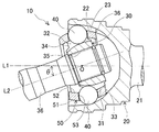
本実施形態のボール型等速ジョイント10(以下、単に「等速ジョイント」と称す)の構成について、図1を参照して説明する。図1は、本実施形態に係る等速ジョイント10の所定角度のジョイント作動角θをとった状態の軸方向断面図である。なお、以下の説明において、外輪20の開口側とは、図1の左側を意味し、外輪20の奥側とは、図1の右側を意味する。
A configuration of the ball type constant velocity joint 10 (hereinafter, simply referred to as “constant velocity joint”) of the present embodiment will be described with reference to FIG. FIG. 1 is a cross-sectional view in the axial direction of the
本実施形態の等速ジョイント10は、図1に示すように、ジョイント中心固定式ボール型等速ジョイント(「ツェッパ形等速ジョイント」とも称す)であって、自動車のフロント用ドライブシャフトのアウトボードジョイントとして好適に使用されるものである。もちろん、リヤ用ドライブシャフトにも適用可能である。特に、本実施形態においては、アンダーカットフリー型(UF)のジョイント中心固定式ボール型等速ジョイントを例に挙げて説明する。
As shown in FIG. 1, the
この等速ジョイント10は、複数の外輪ボール溝23を有する外輪20と、複数の内輪ボール溝32を有する内輪30と、複数のボール40と、保持器50と、シャフト60とを備えて構成されている。以下、各構成部品について詳細に説明する。
The constant velocity joint 10 includes an
外輪20は、図1の左側(本発明の「軸方向一方側」に相当)に開口部を備えるカップ状(有底筒状)に形成されている。この外輪20のカップ底部の外方(図1の右側)には、連結軸21が外輪軸方向に延びるように一体形成されている。この連結軸21は、他の動力伝達軸に連結される。外輪20の内周面は、凹球面状に形成されている。具体的には、外輪20の凹球面状内周面22は、外輪軸線L1と内輪軸線L2との交点Oを曲率中心として描かれる球面の一部により形成されており、外輪軸方向に切断した断面で見た場合に凹円弧状に形成されている。
The
さらに、外輪20の内周面には、外輪軸直交方向断面がほぼ凹円弧状の複数の外輪ボール溝23が、ほぼ外輪軸方向に延びるように形成されている。これら複数(本実施形態では6本)の外輪ボール溝23は、径方向に切断した断面で見た場合に、周方向に等間隔(本実施形態においては60度間隔)に形成されている。ここで、外輪軸方向とは、外輪20の中心軸を通る方向、すなわち、外輪20の回転軸方向を意味する。
Further, a plurality of outer
内輪30は、環状に形成され、外輪20の内側に配置されている。この内輪30の外周面31は、凸球面状に形成されている。具体的には、内輪30の凸球面状外周面31は、外輪軸線L1と内輪軸線L2との交点Oを曲率中心として描かれる球面の一部により形成されており、内輪軸方向に切断した断面で見た場合に凸円弧状に形成されている。
The
また、内輪30の外周面には、内輪軸直交方向断面がほぼ円弧凹状の複数の内輪ボール溝32が、ほぼ内輪軸方向に延びるように形成されている。これら複数(本実施形態では6本)の内輪ボール溝32は、径方向に切断した断面で見た場合に、周方向に等間隔(本実施形態では60度間隔)に、且つ、外輪20に形成される外輪ボール溝23と同数形成されている。つまり、それぞれの内輪ボール溝32が、外輪20のそれぞれの外輪ボール溝23に対向するように位置する。
A plurality of inner
隣り合う内輪ボール溝32の間には、これらの内輪ボール溝32のそれぞれの壁面により構成され、径方向外方に突出する溝壁突条部33がそれぞれ形成されている。各溝壁突条部33の軸方向一端側(図1の左側)の凸球面状外周面31側には、径方向内方に向かって第一切欠34が設けられている。さらに、各溝壁突条部33の軸方向他端側(図1の右側)の凸球面状外周面31側には、径方向内方に向かって第二切欠36が設けられている。この第一切欠34および第二切欠36により、溝壁突条部33の半径方向先端部の軸方向長さが短くされている。第一切欠34および第二切欠36の詳細については、図2を参照して後述する。この第一切欠34および第二切欠36は、全ての溝壁突条部33に形成しているが、一つの溝壁突条部33のみに形成してもよい。
Between the adjacent inner
また、内輪30の内周面には、内輪軸方向に延びる内歯スプライン35が形成されている。この内歯スプライン35は、シャフト60の外歯スプラインに嵌合(噛合)されている。ここで、内輪軸方向とは、内輪30の中心軸を通る方向、すなわち、内輪30の回転軸方向を意味する。
An
複数のボール40は、それぞれ、外輪20の外輪ボール溝23と、当該外輪ボール溝23に対向する内輪30の内輪ボール溝32に挟まれるように配置されている。そして、それぞれのボール40は、それぞれの外輪ボール溝23およびそれぞれの内輪ボール溝32に対して、転動自在で周方向(外輪軸回りまたは内輪軸回り)に係合している。従って、ボール40は、外輪20と内輪30との間でトルクを伝達する。
Each of the plurality of
保持器50は、環状に形成されている。この保持器50の外周面51は、外輪20の凹球面状内周面22にほぼ対応する部分球面状、すなわち凸球面状に形成されている。一方、保持器50の内周面52は、内輪30の凸球面状外周面31にほぼ対応する部分球面状、すなわち凹球面状に形成されている。この保持器50は、外輪20の凹球面状内周面22と内輪30の凸球面状外周面31との間に配置されている。この保持器50は、周方向(保持器軸心の周方向)に等間隔に配置された、ほぼ矩形の貫通孔である複数の窓部53を有する。保持器50の窓部53は、ボール40と同数形成されている。そして、それぞれの窓部53に、ボール40が1つずつ収容されている。各窓部53の4箇所の角部は円弧凹状に形成されている。これにより、隣り合う窓部53の間に位置するそれぞれの柱部の強度および剛性の向上が図られている。
The
次に、図2を参照して、内輪30の詳細、特に第一切欠34および第二切欠36について説明する。図2に示すように、内輪ボール溝32の溝底は、交点Oから外輪20の奥側(図1の右側、図2の右側)へのオフセット点bを曲率中心として描かれる円弧状の曲線状溝底32aと、その曲線状溝底32aの一端から内輪軸方向に延びる直線状溝底32bとにより形成されている。
Next, the details of the
本実施形態の等速ジョイント10のトルク伝達可能なジョイント作動角100、すなわち等速ジョイント10の使用状態時における外輪20とシャフト60とのなす角度は、例えば40°〜50°の範囲に設定され、図2において矢印範囲として示している。そして、トルク伝達可能なジョイント作動角100のうち内輪30の軸方向一方側(図2の左側)において、ボール40が内輪ボール溝32を転動する際のボール40の中心軌跡110は、円弧状に設定されている。また、当該ジョイント作動角100のうち内輪30の軸方向他方側(図2の右側)において、ボール40が内輪ボール溝32を転動する際のボール40の中心軌跡110は、内輪軸方向に沿った形状に設定されている。つまり、ジョイント作動角100が最大の時に、実際の使用状態であるトルク伝達時におけるボール40の中心軌跡110は、P1とP2の間となる。
The
ここで、図1を参照した説明において、内輪ボール溝32の内輪軸直交方向断面は、ほぼ凹円弧状に形成されるとした。詳細には、内輪ボール溝32は、例えば、中心の異なる二つの凹円弧状を接続した、いわゆるゴシックアーク形状に形成される。従って、内輪ボール溝32とボール40との接点軌跡120は、内輪30の軸直交方向から見た場合には、図2の破線にて示すように、内輪ボール溝32の溝底32a,32bから径方向外方にずれた位置となる。また、内輪ボール溝32とボール40との接点軌跡120は、内輪30の軸方向から見た場合には、図示しないが内輪ボール溝32において周方向にずれた2カ所となる。
Here, in the description with reference to FIG. 1, it is assumed that the inner ring axial cross section of the inner
そして、内輪ボール溝32のうちトルク伝達可能なジョイント作動角100の範囲において、内輪ボール溝32にてボール40を転動させた場合に、内輪ボール溝32とボール40との接点軌跡120は、図2の破線にて示す軌跡(P3とP4の間)となる。つまり、接点軌跡120の軸方向一方側(図2の左側)の端点P3は、ボール40の中心軌跡110の軸方向一方側の端点P1とオフセット点bとを結ぶ直線上に位置する。一方、接点軌跡120の軸方向他方側(図2の右側)の端点P4は、ボール40の中心軌跡110の軸方向他方側の端点P2から内輪30の回転軸に向かう垂線上に位置する。そして、当該接点軌跡120は、内輪ボール溝32の溝底が円弧状の曲線の範囲(曲線状溝底32aの範囲)においては、ほぼ円弧状となり、内輪ボール溝32の溝底が直線の範囲(直線状溝底32bの範囲)においては、ほぼ直線状となる。
When the
第一切欠34は、内輪ボール溝32の溝底が円弧状の曲線となる範囲(曲線状溝底32aの範囲)の端部に形成されている。この第一切欠34の径方向内方底部は、内輪ボール溝32におけるボール40との接点軌跡よりも径方向外方に位置するように設定されている。つまり、第一切欠34が形成されている軸方向位置に、内輪ボール溝32とボール40との接点軌跡120が設定されるように、第一切欠34が形成されている。
The
一方、第二切欠36は、内輪ボール溝32の溝底が直線状となる範囲(直線状溝底32bの範囲)の端部に形成されている。この第二切欠36が形成されている軸方向位置は、トルク伝達時における内輪ボール溝32とボール40との接点軌跡120より軸方向他方側に設定されている。つまり、第二切欠36は、接点軌跡120の軸方向他方側の端点P4よりも軸方向他方側(図2の右側)に形成されている。
On the other hand, the
つまり、この第二切欠36の径方向内方底部は、内輪ボール溝32とボール40との接点軌跡120の延長線よりも径方向内方に位置するように設定されている。当該接点軌跡120の延長線とは、接点軌跡120の曲率を維持してそのまま延長させた線である。つまり、本実施形態においては、軸方向他方側の接点軌跡120は、直線状であるため、その直線をそのまま延長した直線となる。
That is, the radially inner bottom portion of the
さらに、第二切欠36の径方向内方底部は、内輪30のうち第二切欠36が形成されている軸方向位置において、内輪ボール溝32の直線状溝底32bよりも径方向外方に位置するように設定されている。つまり、内輪30のうち第二切欠36が形成されている軸方向位置において、内輪ボール溝32が僅かながら形成されていることになる。
Further, the radially inner bottom portion of the
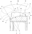
次に、上記のように構成された内輪30を保持器50に組み付ける場合について、図3(a)(b)を参照して詳細に説明する。内輪30を保持器50の内側に組み付けるには、図3(a)(b)に示すように、まず、内輪30の軸方向と保持器50の軸方向をほぼ直交させた状態とする。この状態で、保持器50の内周面の一端側(図3(a)の右側)に形成された導入面54に、内輪30の内輪ボール溝32を跨がせて内輪ボール溝32の間の1つの溝壁突条部33を窓部53内に挿入する。ここで、内輪30の溝壁突条部33の軸方向一端側(図3(b)の左側)には、第一切欠34が形成され、内輪30の溝壁突条部33の軸方向他端側(図3(b)の右側)には、第二切欠36が形成されている。従って、内輪30の1つの溝壁突条部33を保持器50の窓部53内に干渉することなく容易に挿入することができる。
Next, the case where the inner ring |
その後、挿入された溝壁突条部33付近を中心として内輪30を図3(a)に示す矢印X方向に回転させて保持器50内に入れる。続いて、内輪30の凸球面状外周面31の中心点を保持器50の内周面52の中心点に合わせてから内輪30を90°回転させて、内輪30の軸方向と保持器50の軸方向とを一致させる。このように、内輪30の凸球面状外周面31と保持器50の内周面52を球面係合させることにより、内輪30と保持器50の組み付けが完了する。
Thereafter, the
なお、このようにして組み付けられた内輪30と保持器50とを、外輪20の内側に配置する。続いて、ボール40を1つずつ、外輪ボール溝23、内輪ボール溝32および保持器50の窓部53に挿入していく。最後に、シャフト60を内輪30の内側に挿入して、等速ジョイント10の組み付けを完成する。
The
上述したように、内輪30の溝壁突条部33の軸方向両端に切欠(第一切欠34および第二切欠36)を形成することにより、従来に比べて、同程度の等速ジョイント10の大きさであれば、当該溝壁突条部33を保持器50の窓部53へより深く挿入することができる。換言すると、等速ジョイント10を小型化したとしても、保持器50の内側に内輪30を組み付けることができる。ここで、内輪30を組み付けるために、保持器50の柱部を細くすることもないため、保持器50の強度および剛性を従来と同程度に確保することができる。このように、保持器50の強度および剛性を確保しつつ、等速ジョイント10の小型化を図ることができる。
As described above, by forming the notches (the
また、内輪30の軸方向一方側においてボール40の中心軌跡110が円弧状の場合には、第一切欠34の形成前の溝壁突条部33の外周面から曲線状溝底32aまでの距離は十分に長い。この第一切欠34の径方向深さを十分に深くしたとしても、内輪ボール溝32とボール40との接点軌跡120を設定することができる。そして、軸方向他方側の溝壁突条部33にも第二切欠36を形成しているため、軸方向一方側の溝壁突条部33の第一切欠34の径方向深さを、内輪ボール溝32とボール40との接点軌跡120が確保できないほどに設定することなく、内輪30と保持器50との組み付けが可能となる。
Further, when the
ところで、従来に比べて、ジョイント作動角100を所定の角度(フロント用ドライブシャフトに要求される角度、例えば40°〜50°)として、内輪30の外径を小さくするように設計変更した場合には、トルク伝達時、すなわち等速ジョイント10の使用状態におけるボール40の動作範囲は短くなる。このことは、ある点を中心とした円弧長は、半径が大きいほど長くなり、半径が小さいほど短くなる関係から明らかである。一方、内輪30の内周面には、シャフト60の外周面とトルク伝達を可能とするために、内歯スプラインが形成されている。必要なトルクを伝達するためには、当該内歯スプライン35の軸方向長さは設計上決定される。つまり、内輪30の軸方向長さは、内歯スプライン35の軸方向長さから決定される。従って、内輪30の外径の小型化を図ることによりボールの動作範囲が狭くなるのに対して、必要な内輪30の軸方向長さは従来と変わらないため、内輪ボール溝32において内輪ボール溝32とボール40との接点軌跡120を確保しなくてもよい部分が存在することになる。そこで、この部分を利用して、第二切欠36を形成している。
By the way, when the
つまり、第二切欠36が形成される軸方向位置は、内輪ボール溝32とボール40との接点軌跡120が設定されないようにしている。これにより、第二切欠36の径方向深さを十分に深くすることができる。このことからも、内輪30および保持器50を小型化したとしても、内輪30と保持器50の組み付けが可能となる。
That is, the
また、軸方向他方側(図2の右側)のボール40の中心軌跡110は、内輪30の軸方向に沿った形状、すなわち直線状としている。この場合には、図2から明らかなように、軸方向一方側(図2の左側)の内輪ボール溝32の溝深さよりも、軸方向他方側の内輪ボール溝32の溝深さが浅くなっている。そのため、仮に、接点軌跡120を確保しようとすると、第二切欠36は、十分な径方向深さを確保することが容易ではない。しかし、第二切欠36は、内輪ボール溝32とボール40との接点軌跡120を確保することなく形成しているため、径方向深さの深い第二切欠36を形成することができる。このように、第二切欠36の径方向深さをできる限り深くすることができることによっても、内輪30および保持器50を小型化したとしても、内輪30と保持器50の組み付けが可能となる。
Further, the
なお、上記実施形態においては、アンダーカットフリー型(UF)のジョイント中心固定式ボール型等速ジョイントについて説明したが、特開2008−008323号公報などに記載のバーフィールド型(BF)のジョイント中心固定式ボール型等速ジョイントに対しても、第一切欠34と第二切欠36を形成することができる。この場合も、等速ジョイントの小型化を図りつつ、内輪30と保持器50の組み付けが可能となる。また、ジョイント固定式ボール型等速ジョイントの他に、ダブルオフセット型摺動式等速ジョイントにも適用した場合にも、等速ジョイントの小型化を図りつつ、内輪30と保持器50の組み付けが可能となる。
In the above embodiment, an undercut free type (UF) joint center fixed ball type constant velocity joint has been described. However, a bar field type (BF) joint center described in Japanese Patent Application Laid-Open No. 2008-008323 and the like is described. The
10:ボール型等速ジョイント
20:外輪、 21:連結軸、 22:凹球面状内周面、 23:外輪ボール溝
30:内輪、 31:凸球面状外周面、 32:内輪ボール溝、 32a:曲線状溝底
32b:直線状溝底、 33:溝壁突条部、 34:第一切欠、 35:内歯スプライン
36:第二切欠
40:ボール
50:保持器、 53:窓部、 54:導入面
60:シャフト
100:ジョイント作動角、 110:ボールの中心軌跡
120:内輪ボール溝とボールとの接点軌跡
10: Ball type constant velocity joint 20: Outer ring, 21: Connecting shaft, 22: Concave spherical inner peripheral surface, 23: Outer ring ball groove 30: Inner ring, 31: Convex spherical outer peripheral surface, 32: Inner ring ball groove, 32a:
Claims (3)
前記外輪の内側に配置され、外周面に内輪ボール溝が複数形成された内輪と、
それぞれの前記外輪ボール溝および前記内輪ボール溝を転動し、前記外輪と前記内輪との間でトルクを伝達する複数のボールと、
環状に形成され、前記外輪と前記内輪との間に配置され、周方向に前記ボールをそれぞれ収容する複数の窓部が形成された保持器と、
を備えるボール型等速ジョイントにおいて、
前記内輪の軸方向一方側において、前記内輪ボール溝の溝底は、円弧状に設定され、
前記内輪の軸方向他方側において、前記内輪ボール溝の溝底は、直線状に設定され、
隣り合う前記内輪ボール溝の側壁面により構成される複数の溝壁突条部のうち少なくとも1つには、前記内輪の軸方向一方側の端部の前記内輪の外周側であって前記内輪ボール溝の溝底が円弧状となる軸方向範囲に第一切欠が形成され、前記内輪の軸方向他方側の端部の前記内輪の外周側であって前記内輪ボール溝の溝底が直線状となる軸方向範囲に第二切欠が形成され、
前記第一切欠が形成されている軸方向位置には、前記内輪ボール溝と前記ボールとの接点軌跡が設定され、
前記第二切欠が形成されている軸方向位置は、トルク伝達時における前記内輪ボール溝と前記ボールとの接点軌跡より前記軸方向他方側に設定され、
前記第二切欠の径方向内方底部は、前記接点軌跡の延長線より径方向内方に位置するように設定されるボール型等速ジョイント。 An outer ring formed in a cylindrical shape having an opening at least in one axial direction, and a plurality of outer ring ball grooves formed on the inner peripheral surface;
An inner ring disposed inside the outer ring and having a plurality of inner ring ball grooves formed on the outer peripheral surface;
A plurality of balls that roll on each of the outer ring ball groove and the inner ring ball groove to transmit torque between the outer ring and the inner ring;
A cage formed in an annular shape, disposed between the outer ring and the inner ring, and formed with a plurality of windows for receiving the balls in the circumferential direction;
In a ball-type constant velocity joint comprising
On the one axial side of the inner ring, the groove bottom of the inner ring ball groove is set in an arc shape,
On the other side in the axial direction of the inner ring, the groove bottom of the inner ring ball groove is set linearly,
At least one of the plurality of groove wall ridges constituted by the side wall surfaces of the adjacent inner ring ball grooves includes an outer peripheral side of the inner ring at one end in the axial direction of the inner ring and the inner ring ball A first notch is formed in the axial range in which the groove bottom of the groove is arcuate, and the groove bottom of the inner ring ball groove is linear on the outer peripheral side of the inner ring at the other axial end of the inner ring. A second notch is formed in the axial range,
A contact locus between the inner ring ball groove and the ball is set at an axial position where the first notch is formed,
The axial position where the second notch is formed is set on the other side in the axial direction from the contact locus between the inner ring ball groove and the ball during torque transmission ,
Said second radially inner bottom of the notches, the ball type constant velocity joint that will be set so as to be located radially inward from the extension of the contact path.
前記内輪の軸方向一方側において、前記ボールが前記内輪ボール溝を転動する際の前記ボールの中心軌跡は、円弧状に設定され、
前記第一切欠は、前記中心軌跡が円弧状の軸方向範囲に形成されるボール型等速ジョイント。 In claim 1,
On one side in the axial direction of the inner ring, the center locus of the ball when the ball rolls in the inner ring ball groove is set in an arc shape,
The first part is a ball-type constant velocity joint in which the central locus is formed in an arc-shaped axial range.
前記内輪の前記軸方向他方側において、前記ボールが前記内輪ボール溝を転動する際の前記ボールの中心軌跡は、前記内輪の軸方向に沿った形状に設定され、
前記第二切欠は、前記中心軌跡が前記内輪の軸方向に沿った形状の軸方向範囲に形成されるボール型等速ジョイント。 In claim 1 or 2,
On the other side in the axial direction of the inner ring, the center locus of the ball when the ball rolls in the inner ring ball groove is set to a shape along the axial direction of the inner ring,
The second notch is a ball-type constant velocity joint in which the center locus is formed in an axial range having a shape along the axial direction of the inner ring.
Priority Applications (5)
| Application Number | Priority Date | Filing Date | Title |
|---|---|---|---|
| JP2010154645A JP5740857B2 (en) | 2010-07-07 | 2010-07-07 | Ball type constant velocity joint |
| EP11803540.1A EP2592293B1 (en) | 2010-07-07 | 2011-07-04 | Ball type constant velocity joint |
| US13/807,834 US8808098B2 (en) | 2010-07-07 | 2011-07-04 | Ball type constant velocity joint |
| PCT/JP2011/065262 WO2012005206A1 (en) | 2010-07-07 | 2011-07-04 | Ball type constant velocity joint |
| CN201180031557.6A CN102959261B (en) | 2010-07-07 | 2011-07-04 | Ball type constant velocity joint |
Applications Claiming Priority (1)
| Application Number | Priority Date | Filing Date | Title |
|---|---|---|---|
| JP2010154645A JP5740857B2 (en) | 2010-07-07 | 2010-07-07 | Ball type constant velocity joint |
Related Child Applications (1)
| Application Number | Title | Priority Date | Filing Date |
|---|---|---|---|
| JP2014262625A Division JP5967185B2 (en) | 2014-12-25 | 2014-12-25 | Ball type constant velocity joint |
Publications (3)
| Publication Number | Publication Date |
|---|---|
| JP2012017787A JP2012017787A (en) | 2012-01-26 |
| JP2012017787A5 JP2012017787A5 (en) | 2014-02-27 |
| JP5740857B2 true JP5740857B2 (en) | 2015-07-01 |
Family
ID=45441185
Family Applications (1)
| Application Number | Title | Priority Date | Filing Date |
|---|---|---|---|
| JP2010154645A Active JP5740857B2 (en) | 2010-07-07 | 2010-07-07 | Ball type constant velocity joint |
Country Status (5)
| Country | Link |
|---|---|
| US (1) | US8808098B2 (en) |
| EP (1) | EP2592293B1 (en) |
| JP (1) | JP5740857B2 (en) |
| CN (1) | CN102959261B (en) |
| WO (1) | WO2012005206A1 (en) |
Families Citing this family (1)
| Publication number | Priority date | Publication date | Assignee | Title |
|---|---|---|---|---|
| JP7102195B2 (en) * | 2018-04-04 | 2022-07-19 | 株式会社ジェイテクト | Constant velocity joint |
Family Cites Families (12)
| Publication number | Priority date | Publication date | Assignee | Title |
|---|---|---|---|---|
| US5509857A (en) * | 1993-12-17 | 1996-04-23 | General Motors Corporation | Constant velocity universal joint |
| JP2000145805A (en) * | 1998-11-11 | 2000-05-26 | Nsk Ltd | Constant velocity universal joint and automobile hub unit with constant velocity universal joint |
| JP3678026B2 (en) | 1998-11-19 | 2005-08-03 | 豊田工機株式会社 | Constant velocity joint |
| DE10032854C1 (en) * | 2000-07-06 | 2002-04-04 | Gkn Loebro Gmbh | Ball constant velocity joint |
| US6817950B2 (en) * | 2002-11-14 | 2004-11-16 | Gkn Driveline North America, Inc. | High angle constant velocity joint |
| US7211002B2 (en) * | 2002-11-14 | 2007-05-01 | Gkn Driveline North America, Inc. | High angle constant velocity joint |
| US20050101391A1 (en) * | 2003-11-10 | 2005-05-12 | Ingalsbe Steven L. | Constant velocity joint having friction reducing web locators |
| JP4339144B2 (en) * | 2004-02-12 | 2009-10-07 | Ntn株式会社 | Fixed type constant velocity universal joint |
| DE102004023817A1 (en) * | 2004-05-13 | 2005-12-08 | Volkswagen Ag | Constant velocity joint for e.g. drive shaft, has magnetic particle collecting zone arranged outside of joint function surfaces and remotely from sealing device, where collecting zone is formed by fastened magnet units |
| JP4729445B2 (en) | 2006-06-27 | 2011-07-20 | トヨタ自動車株式会社 | Constant velocity joint |
| JP2008309221A (en) * | 2007-06-13 | 2008-12-25 | Ntn Corp | Fixed type constant velocity universal joint |
| JP5138449B2 (en) * | 2008-04-08 | 2013-02-06 | Ntn株式会社 | Constant velocity universal joint |
-
2010
- 2010-07-07 JP JP2010154645A patent/JP5740857B2/en active Active
-
2011
- 2011-07-04 US US13/807,834 patent/US8808098B2/en active Active
- 2011-07-04 WO PCT/JP2011/065262 patent/WO2012005206A1/en active Application Filing
- 2011-07-04 EP EP11803540.1A patent/EP2592293B1/en active Active
- 2011-07-04 CN CN201180031557.6A patent/CN102959261B/en active Active
Also Published As
| Publication number | Publication date |
|---|---|
| US8808098B2 (en) | 2014-08-19 |
| EP2592293B1 (en) | 2020-05-06 |
| CN102959261A (en) | 2013-03-06 |
| EP2592293A4 (en) | 2018-04-18 |
| CN102959261B (en) | 2015-05-20 |
| US20130172091A1 (en) | 2013-07-04 |
| EP2592293A1 (en) | 2013-05-15 |
| JP2012017787A (en) | 2012-01-26 |
| WO2012005206A1 (en) | 2012-01-12 |
Similar Documents
| Publication | Publication Date | Title |
|---|---|---|
| JP2007270997A (en) | Fixed type constant velocity universal joint | |
| JP2004239436A (en) | Counter raceway joint with improved cage | |
| JP2006266329A (en) | Fixed type constant velocity universal joint | |
| JPS5941050B2 (en) | synchronous rotary joint | |
| JP5740857B2 (en) | Ball type constant velocity joint | |
| JP5967185B2 (en) | Ball type constant velocity joint | |
| JP5131064B2 (en) | Ball type constant velocity joint | |
| JP2006242263A (en) | Fixed constant velocity universal joint and its manufacturing method | |
| JP4896662B2 (en) | Fixed constant velocity universal joint | |
| JP2001349332A (en) | Fixed constant velocity universal joint and assembly method therefor | |
| JP4515377B2 (en) | Fixed type constant velocity universal joint | |
| JP5146769B2 (en) | Ball type constant velocity joint | |
| JP2010185538A (en) | Ball type constant velocity joint | |
| JP2007132379A (en) | Fixed type constant velocity universal joint | |
| JP2012017787A5 (en) | ||
| JP2008051190A (en) | Fixed type constant velocity universal joint | |
| JP2014031821A (en) | Double offset type constant velocity joint | |
| JP4624892B2 (en) | Constant velocity universal joint | |
| JP2007232192A (en) | Fixed type constant velocity universal joint | |
| JP2011069404A (en) | Fixed type constant velocity universal joint | |
| JP5299247B2 (en) | Ball type constant velocity joint | |
| JP2008101656A (en) | Fixed type constant velocity universal joint | |
| JP2010249295A (en) | Fixed constant velocity universal joint and method of manufacturing the same | |
| JP2009144828A (en) | Ball type constant velocity universal joint and its manufacturing method | |
| JP2008051189A (en) | Fixed-type constant-speed universal joint |
Legal Events
| Date | Code | Title | Description |
|---|---|---|---|
| A621 | Written request for application examination |
Free format text: JAPANESE INTERMEDIATE CODE: A621 Effective date: 20130620 |
|
| A521 | Request for written amendment filed |
Free format text: JAPANESE INTERMEDIATE CODE: A523 Effective date: 20140114 |
|
| A131 | Notification of reasons for refusal |
Free format text: JAPANESE INTERMEDIATE CODE: A131 Effective date: 20140225 |
|
| A521 | Request for written amendment filed |
Free format text: JAPANESE INTERMEDIATE CODE: A523 Effective date: 20140414 |
|
| A02 | Decision of refusal |
Free format text: JAPANESE INTERMEDIATE CODE: A02 Effective date: 20140930 |
|
| A521 | Request for written amendment filed |
Free format text: JAPANESE INTERMEDIATE CODE: A523 Effective date: 20141225 |
|
| A911 | Transfer to examiner for re-examination before appeal (zenchi) |
Free format text: JAPANESE INTERMEDIATE CODE: A911 Effective date: 20150109 |
|
| TRDD | Decision of grant or rejection written | ||
| A01 | Written decision to grant a patent or to grant a registration (utility model) |
Free format text: JAPANESE INTERMEDIATE CODE: A01 Effective date: 20150331 |
|
| A61 | First payment of annual fees (during grant procedure) |
Free format text: JAPANESE INTERMEDIATE CODE: A61 Effective date: 20150413 |
|
| R150 | Certificate of patent or registration of utility model |
Ref document number: 5740857 Country of ref document: JP Free format text: JAPANESE INTERMEDIATE CODE: R150 |