JP5737366B2 - Electrochemical cell - Google Patents
Electrochemical cell Download PDFInfo
- Publication number
- JP5737366B2 JP5737366B2 JP2013233159A JP2013233159A JP5737366B2 JP 5737366 B2 JP5737366 B2 JP 5737366B2 JP 2013233159 A JP2013233159 A JP 2013233159A JP 2013233159 A JP2013233159 A JP 2013233159A JP 5737366 B2 JP5737366 B2 JP 5737366B2
- Authority
- JP
- Japan
- Prior art keywords
- gas
- exterior body
- amount
- electrochemical cell
- lithium ion
- Prior art date
- Legal status (The legal status is an assumption and is not a legal conclusion. Google has not performed a legal analysis and makes no representation as to the accuracy of the status listed.)
- Active
Links
Images


Classifications
-
- Y—GENERAL TAGGING OF NEW TECHNOLOGICAL DEVELOPMENTS; GENERAL TAGGING OF CROSS-SECTIONAL TECHNOLOGIES SPANNING OVER SEVERAL SECTIONS OF THE IPC; TECHNICAL SUBJECTS COVERED BY FORMER USPC CROSS-REFERENCE ART COLLECTIONS [XRACs] AND DIGESTS
- Y02—TECHNOLOGIES OR APPLICATIONS FOR MITIGATION OR ADAPTATION AGAINST CLIMATE CHANGE
- Y02E—REDUCTION OF GREENHOUSE GAS [GHG] EMISSIONS, RELATED TO ENERGY GENERATION, TRANSMISSION OR DISTRIBUTION
- Y02E60/00—Enabling technologies; Technologies with a potential or indirect contribution to GHG emissions mitigation
- Y02E60/10—Energy storage using batteries
-
- Y—GENERAL TAGGING OF NEW TECHNOLOGICAL DEVELOPMENTS; GENERAL TAGGING OF CROSS-SECTIONAL TECHNOLOGIES SPANNING OVER SEVERAL SECTIONS OF THE IPC; TECHNICAL SUBJECTS COVERED BY FORMER USPC CROSS-REFERENCE ART COLLECTIONS [XRACs] AND DIGESTS
- Y02—TECHNOLOGIES OR APPLICATIONS FOR MITIGATION OR ADAPTATION AGAINST CLIMATE CHANGE
- Y02P—CLIMATE CHANGE MITIGATION TECHNOLOGIES IN THE PRODUCTION OR PROCESSING OF GOODS
- Y02P70/00—Climate change mitigation technologies in the production process for final industrial or consumer products
- Y02P70/50—Manufacturing or production processes characterised by the final manufactured product
Landscapes
- Sealing Battery Cases Or Jackets (AREA)
- Secondary Cells (AREA)
Description
本発明は、外装体内部で増加するガス増加量に基づいて設計された電気化学セルに関する。 The present invention relates to an electrochemical cell designed based on an amount of gas increase that increases inside an exterior body.
リチウムイオン電池とは、リチウム二次電池ともいわれ、液状、ゲル状又は高分子ポリマー状の電解質を持ち、正極・負極活物質が高分子ポリマーからなるものを含むものである。このリチウムイオン電池は、充電時には正極活物質であるリチウム遷移金属酸化物中のリチウム原子(Li)がリチウムイオン(Li+)となって負極の炭素層間に入り込み(インターカレーション)、放電時にはリチウムイオン(Li+)が炭素層間から離脱(デインターカレーション)して正極に移動し、元のリチウム化合物となることにより充放電反応が進行する電池であり、ニッケル・カドミウム電池やニッケル水素電池より出力電圧が高く、高エネルギー密度である上、浅い放電と再充電を繰り返すことにより見掛け上の放電容量が低下する、いわゆるメモリー効果がないという優れた特長を有している。 The lithium ion battery is also referred to as a lithium secondary battery, and includes a liquid, gel-like, or polymer polymer electrolyte, and a positive electrode / negative electrode active material made of a polymer polymer. In this lithium ion battery, lithium atoms (Li) in a lithium transition metal oxide, which is a positive electrode active material, are charged as lithium ions (Li + ) during charging and enter the carbon layer of the negative electrode (intercalation). This is a battery in which charge / discharge reaction proceeds when ions (Li + ) are separated from the carbon layer (deintercalation) and move to the positive electrode to become the original lithium compound. From the nickel-cadmium battery and the nickel-hydrogen battery The output voltage is high, the energy density is high, and the apparent discharge capacity is reduced by repeating shallow discharge and recharging, so that there is no so-called memory effect.
また、リチウムイオン電池の構成は、正極集電材/正極活性物質層/電解質層/負極活性物質層/負極集電材及び、これらを包装する外装体からなり、外装体を形成する包装材料として従来、金属をプレス加工し円筒状または直方体状等に容器化した金属製缶が用いられていた。 In addition, the configuration of the lithium ion battery is composed of a positive electrode current collector / positive electrode active material layer / electrolyte layer / negative electrode active material layer / negative electrode current collector and an outer package that wraps these, and as a packaging material for forming the outer package, Metal cans that are made by pressing a metal into a cylindrical shape or a rectangular parallelepiped shape have been used.
しかし、金属製缶は、容器外壁がリジッドであるため、電池自体の形状が限定されてしまい、ハード側を電池に合わせて設計する必要から形状の自由度がないため、近年、金属製缶に替わって多層フィルムが包装材料として用いられる傾向にある。 However, since the outer wall of the container is rigid, the shape of the battery itself is limited, and there is no degree of freedom in shape because it is necessary to design the hardware side to match the battery. Instead, multilayer films tend to be used as packaging materials.
包装材料の材質構成は、電池としての必要な物性、加工性、経済性等から、少なくとも基材層、バリア層、シール層と前記各層を接着する接着層からなる。この包装材料を袋状に形成し電池本体を収納するパウチタイプ、または、包装材料をプレス加工して凹部を形成し、凹部に電池本体を収納するエンボスタイプの電池用外装体が形成される。 The material composition of the packaging material is composed of at least a base material layer, a barrier layer, a seal layer, and an adhesive layer that bonds the respective layers in view of necessary physical properties, workability, economy, and the like as a battery. A pouch type in which the packaging material is formed in a bag shape and the battery body is accommodated, or an embossed type battery exterior body in which the packaging material is pressed to form a recess and the battery body is accommodated in the recess is formed.
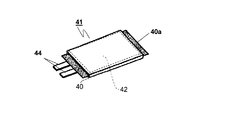
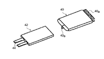
図6は、従来のパウチタイプのリチウムイオン電池41の斜視図であり、図7は、図6に示したパウチタイプのリチウムイオン電池41を分解して示す分解斜視図である。図6及び図7に示すように、パウチタイプのリチウムイオン電池41は最内層のシール層同士を重ね合わせ、外装体40の周縁部であるヒートシール部40aをヒートシールすることによりパウチタイプの外装体40が形成され、外装体40内にリチウムイオン電池本体42を収納し、開口部をヒートシールしてリチウムイオン電池本体42を密封収納する。
6 is a perspective view of a conventional pouch-type lithium ion battery 41, and FIG. 7 is an exploded perspective view showing the pouch-type lithium ion battery 41 shown in FIG. 6 in an exploded manner. As shown in FIGS. 6 and 7, the pouch-type lithium ion battery 41 has a pouch-type exterior by overlapping the innermost seal layers and heat-sealing a
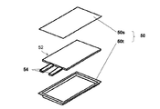
また、図8は従来のエンボスタイプのリチウムイオン電池51の斜視図であり、図9は図8に示したエンボスタイプのリチウムイオン電池51を分解して示す分解斜視図である。図8及び図9に示すように、エンボスタイプのリチウムイオン電池51はエンボス部が形成されたトレイ50tの内部にリチウムイオン電池本体52を収納し、トレイ50tとシート50sのシール層同士を重ね合わせ外装体50の周縁部であるヒートシール部50aをヒートシールすることにより、トレイ50tとシート50sから構成されるエンボスタイプの外装体50内部にリチウムイオン電池本体52を密封収納する。
FIG. 8 is a perspective view of a conventional embossed type
なお、リチウムイオン電池本体42、52は、正極活物質及び正極集電体から成る正極と、負極活物質及び負極集電体から成る負極と、正極及び負極間に充填される電解質と(いずれも図示せず)を含むセル(蓄電部)と、セル内の正極及び負極に連結されるとともに先端が外装体40、50の外部に突出する金属端子44、54から構成されている。また、金属端子44,54と外装体40、50の最内層のシール層間には双方に熱接着性を有するタブフィルムが介され、金属端子44、54とシール層との接着性を安定化させている。
The lithium
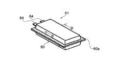
また、図10は従来のエンボスタイプのリチウムイオン電池61の斜視図であり、図11は図10中で示すリチウムイオン電池61のB−B’における断面図である。図11に示すように、外装体60は最内層のシール層13同士を重ね合わせ、外装体60の周縁部をヒートシールすることにより外装体周縁部(ヒートシール部60a)を接着し、外装体60内部にリチウムイオン電池本体62を密封収納している。なお、外装体60を構成する包装材料は少なくとも基材層31、バリア層32、シール層33を積層して構成される積層フィルムである。
10 is a perspective view of a conventional embossed type
ここで、外装体60内部では、リチウムイオン電池61の充放電により電解質と電極の間でイオンの交換がおこなわれており、この過程で少量の二酸化炭素、水素、酸素等の複数類のガスが発生する。特に急速な充放電や過充電をした場合、これらのガスが発生し易く、これらのガスは充放電を繰り返すことで、徐々に外装体60内部に蓄積して外装体60の内圧を上昇させる。内圧が上昇し続けた場合、発生したガスはシール層13を介して外装体60内部から外装体60外部に透過して放出され、外装体60の内圧の上昇が抑えられる(図11参照)。しかし、発生するガスの発生速度が外装体60外部に透過するガスのガス透過速度を超えた場合、最終的に外装体60が内圧に抗しきれず破裂することがある。
Here, inside the
そこで、これらの問題を解決するため、従来、外装体60内部に電解質を含むリチウムイオン電池本体62の収納領域以外に外装体60内部で発生したガスを収容するためのデッドスペース(以下、第1空間とする)が設けられていた。また、特許文献1に記載のリチウム電池では外装体内部で発生したガスを外部に放出するための安全弁が設けられていた。
Therefore, in order to solve these problems, conventionally, a dead space (hereinafter referred to as a first space) for containing the gas generated inside the
ここで、第1空間の容積を大きく設けると、外装体60内部で発生するガスを第1空間に一定量収納することができ、外装体60外部へ発生したガスを透過させながら、外装体60内部のガス増加量を調整し、内圧の上昇を抑えることができる。しかし、第1空間の容積を大きく設けすぎると、外装体60全体の容積も併せて大きくなり、リチウムイオン電池61の体積当たりの出力が低下することが問題となっていた。また、特許文献1に示すように安全弁を設けた場合、製造コストの面で問題があった。
Here, if the volume of the first space is increased, a certain amount of gas generated inside the
また、上記リチウムイオン電池本体42、52,62を外装体40、50、60に収納する場合の他、キャパシタ、電気二重層キャパシタ等の電気化学セル本体を収納し密封シールした場合にも内部でガスが発生し同様の問題が生じていた。
Further, in addition to the case where the lithium ion battery
そこで、本発明は上記問題点に鑑み、外装体内部で発生したガスを収納するための空間の容積を最適の大きさに設計して、内圧の上昇による外装体の破裂を防ぐとともに、電気化学セル全体の容積を最適な大きさに設計して提供することを目的とする。 Therefore, in view of the above problems, the present invention is designed to optimize the volume of the space for storing the gas generated inside the exterior body to prevent the exterior body from bursting due to an increase in internal pressure, and to perform electrochemical The object is to design and provide the optimal volume of the entire cell.
上記目的を達成するために本発明の構成は、正極活物質及び正極集電体から成る正極と、負極活物質及び負極集電体から成る負極と、前記正極及び前記負極間に充填される電解質とを含む電気化学セル本体を、基材層と、バリア層と、シール層とを、少なくとも順次積層して構成される積層体からなる外装体内に収納し、前記外装体の周縁部をヒートシールして形成される電気化学セルであって、前記外装体内部には前記電気化学セル本体と前記外装体との間に形成される第1空間を有し、前記第1空間の容積は、前記電気化学セルの使用期間に応じた前記外装体内部のガス増加量に基づいて導き出されることを特徴とする。 In order to achieve the above object, the present invention comprises a positive electrode comprising a positive electrode active material and a positive electrode current collector, a negative electrode comprising a negative electrode active material and a negative electrode current collector, and an electrolyte filled between the positive electrode and the negative electrode. An electrochemical cell main body containing a base material layer, a barrier layer, and a seal layer in an exterior body composed of a laminate formed by sequentially laminating, and heat-sealing the peripheral portion of the exterior body The outer surface of the electrochemical cell has a first space formed between the electrochemical cell body and the outer body, and the volume of the first space is It is derived based on the amount of gas increase in the exterior body according to the period of use of the electrochemical cell.
本発明の第2の構成は、上記電気化学セルにおいて、前記ガス増加量は前記外装体内部で発生するガス発生量と前記外装体内部から前記外装体外部へ透過するガス透過量との差により導き出され、前記ガス透過量は、前記シール層に用いるシーラントフィルムの所定透過面積及び所定透過厚さにおけるガス透過量と、前記外装体においてヒートシールされる前記シール層の断面積と、前記外装体においてヒートシールされるシール幅と、を基に導きだされることを特徴とする。 According to a second configuration of the present invention, in the electrochemical cell, the gas increase amount is based on a difference between a gas generation amount generated inside the exterior body and a gas permeation amount permeating from the interior of the exterior body to the exterior of the exterior body. The gas permeation amount is derived from the gas permeation amount at a predetermined permeation area and a predetermined permeation thickness of the sealant film used for the seal layer, the cross-sectional area of the seal layer heat-sealed in the outer body, and the outer body. It is derived on the basis of the seal width to be heat-sealed.
本発明の第1の構成によると、外装体内部で発生したガスは外装体内部で電気化学セル本体と外装体との間に形成された第1空間に収納される。このとき、第1空間の容積は電気化学セルの使用期間に応じた外装体内部のガス増加量に基づいて導き出されているため、電気化学セルの使用期間中、外装体の内圧の上昇による外装体の破裂を防ぐことができる。また、電気化学セル全体の容積を最適な大きさに設計して、電気化学セルの体積当たりの出力を確保することができる。 According to the first configuration of the present invention, the gas generated inside the exterior body is stored in the first space formed between the electrochemical cell main body and the exterior body inside the exterior body. At this time, since the volume of the first space is derived based on the amount of gas increase in the exterior body corresponding to the period of use of the electrochemical cell, the exterior due to an increase in the internal pressure of the exterior body during the period of use of the electrochemical cell. Can prevent body rupture. In addition, the volume of the entire electrochemical cell can be designed to an optimum size, and the output per volume of the electrochemical cell can be ensured.
本発明の第2の構成によると、ガス透過量を、シール層に用いるシーラントフィルムの所定透過面積及び所定透過厚さにおけるガス透過量と、外装体においてヒートシールされるシール層の断面積と、外装体においてヒートシールされるシール幅と、を基に導きだすことにより、ガス透過量を高い精度で予測することができる。これにより、ガス増加量をガス発生量及びガス透過量の差から高い精度で導き出すことができる。したがって、外装体内部の第1空間の容積および電気化学セル全体の容積をより最適な大きさに設計することができる。 According to the second configuration of the present invention, the gas permeation amount, the gas permeation amount at a predetermined permeation area and a predetermined permeation thickness of the sealant film used for the seal layer, and the cross-sectional area of the seal layer heat-sealed in the exterior body, By deriving on the basis of the seal width that is heat-sealed in the exterior body, the gas permeation amount can be predicted with high accuracy. Thereby, the gas increase amount can be derived with high accuracy from the difference between the gas generation amount and the gas permeation amount. Therefore, the volume of the first space inside the exterior body and the volume of the entire electrochemical cell can be designed to be more optimal.
以下、本発明の実施形態について電気化学セルの一種であるリチウムイオン電池について図面を参照しながら説明する。本発明では外装体内部に蓄積されたガスを収容する第1空間を外装体内部に備え、その第1空間の容積を最適な大きさに設計して電気化学セルを提供しようとするものである。なお、従来例の図6〜図11と共通する部分には説明を省略する。 Hereinafter, embodiments of the present invention will be described with reference to the drawings for a lithium ion battery which is a kind of electrochemical cell. In the present invention, a first space for storing gas accumulated in the exterior body is provided inside the exterior body, and the volume of the first space is designed to an optimum size to provide an electrochemical cell. . Note that the description of the portions common to FIGS. 6 to 11 in the conventional example is omitted.
図1はパウチ型のリチウムイオン電池1を模式的に示す平面図であり、図2は図1で示すリチウムイオン電池1をx方向から拡大して示す側面図であり、図3は図1で示すリチウムイオン電池1をy方向から拡大して示す側面図であり、図4は図1で示すリチウムイオン電池1のA−A’における断面を拡大して示す断面図である。図1〜図4に示すように、パウチ型のリチウムイオン電池1は、長方形状のシート片に裁断された包装材料を二つ折りにした後、対向する2辺(ヒートシール部10a)をヒートシールしてパウチ型の外装体10を作成し、外装体10内部にリチウムイオン電池本体22を収納し、金属端子24を挟持した状態で、その挟持部分を含む残りの周縁部(ヒートシール部10a)をヒートシールして作成される。このとき、包装材料は少なくとも基材層11、バリア層12、シール層13を積層して構成される積層フィルムであり(図2〜図4参照)、外装体10は最内層のシール層13同士を重ね合わせ、ヒートシールすることにより接着している。また、金属端子24と最内層のシール層13間には双方に熱接着性を有するタブフィルム25が介され、金属端子24とシール層13との接着性を安定化させている(図3参照)。
FIG. 1 is a plan view schematically showing a pouch-type
また、第1空間20は図1で示されるようにリチウムイオン電池1の正極と負極のタブ材24の中間付近に設けられている。これは、リチウムイオン電池1の収納効率を上げるために最も好適な配置であり、使用態様又はリチウムイオン電池1の収納スペースに応じてタブ材の中間付近以外に配すことも可能である。ここで、第1空間20は外装体10内部で発生したガスを所定量だけ外装体内部に蓄積して内圧の上昇を抑える働きを有するとともに、第1空間に蓄積したガスは外装体10端面において、発生したガスをシール層13から外装体10外部に透過させて、内圧の上昇を抑える。なお、多層フィルムからなる包装材料を用いて形成された外装体10では、外装体10内部でガスが発生したとき外装体10が膨張し、第1空間20は外装体10内部全体に広がり、第1空間20内に蓄積したガスは外装体10周縁のヒートシール部10a全体からシール層13を介して外部に透過する。
Further, as shown in FIG. 1, the
次にこの第1空間20の容積の導き方について説明する。第1空間20はリチウムイオン電池1の外装体10内部で増加するガスの増加量に応じて導き出され、想定されるリチウムイオン電池1の使用期間をt年とすると、t年間で外装体10内部で増加するガス増加量はtの関数V(t)で表すことができる。また、t年間で外装体10内部で発生するガス発生量はtの関数X(t)と表すことができ、t年間で外装体10内部から外装体10外部へ透過するガス透過量はtの関数Y(t)と表すことができる。また。ガス増加量V(t)、ガス発生量X(t)、ガス透過量Y(t)は以下の関係にある。なお、本実施形態においては、外装体10内部で発生する一種類のガスについて検討するが、複数種のガスについて各ガス増加量V(t)をそれぞれ導き出し、その総和により第1空間20の容積を導き出すこともできる。このとき、第1空間20の容積及び電気化学セル11全体の容積をより最適な大きさに設計することができる。
Next, how to derive the volume of the
[式1]
ガス増加量V(t)=ガス発生量X(t)−ガス透過量Y(t)
[Formula 1]
Gas increase amount V (t) = gas generation amount X (t) −gas permeation amount Y (t)
したがって、式1より、ガス発生量X(t)及びガス透過量Y(t)が決定されればガス増加量V(t)を導き出すことができ、ガス発生量X(t)から第1空間20の容積を決定することができる。
Therefore, if the gas generation amount X (t) and the gas permeation amount Y (t) are determined from
ここで、ガス発生量X(t)は外装体10内部に収納された電解質及び、電池の容積、出力、使用環境及び使用態様によりガスの発生量は異なる。したがって、t年後のガス発生量X(t)は所定の上記条件により決定されたデータに基づいてtの関数として算出する必要がある。
Here, the gas generation amount X (t) differs depending on the electrolyte stored in the
また、ガス透過量Y(t)はガスが透過するシール層13に用いるシーラントフィルムの所定透過面積及び所定透過厚さにおけるガス透過量と、外装体10においてヒートシールされるシール層13の断面積Sと、外装体10においてヒートシールされるシール幅Lと、を基に導き出すことができる。ここで、シール層13の断面積Sは外装体10内部から外装体10外部へ透過するガスの透過面積に相当する。また、シール幅Lは外装体10内部から外装体10外部へ透過するガスの透過厚さに相当する。
Further, the gas permeation amount Y (t) is a gas permeation amount in a predetermined permeation area and a predetermined permeation thickness of the sealant film used for the gas-
したがって、図5に示すように、シール層13に用いるシーラントフィルム(透過面積:1m2、透過厚さ:1mm)のガス透過量が、T(℃)、1(atm)の条件下で、1日(24hr)、M(ml・mm/m2・24hr・atm)である場合、以下の一般式からT(℃)の条件下で外装体10のシール層13における1年当たりのガス透過度C[ml/年・atm]を導き出すことができる。なお、このとき、シール層13に用いるシーラントフィルムを理論モデルとし、外装体10のヒートシール部10aにおけるシーラント層35を測定モデルとする。なお、シーラントフィルムのガス透過量MはJIS−K7126Aに準拠する差圧法により導き出すことができる。また、ガス透過量は透過する樹脂の種類及び測定時の温度条件により変化する。従って、複数の温度条件下においてJIS−K7126Aに準拠する差圧法によりガス透過量を導き出し、所定温度における平均的なガス透過量Mを用いることができる。
Therefore, as shown in FIG. 5, the gas permeation amount of the sealant film (permeation area: 1 m 2 , permeation thickness: 1 mm) used for the
[式3]

式3からガス透過量Y(t)のガス透過速度dY(t)/dtは第1空間の気体分圧pの関数で表すことができる。また、初期状態における第1空間20に存在するガス量の初期値をV0、気体分圧の初期値をp0とし、第1空間20の容積がガスの発生により変化しないとすると、第1空間20内部のガス増加量V(t)を用いてt年後の第1空間20の気体分圧pを以下の式で表すことができる。
From Equation 3, the gas permeation rate dY (t) / dt of the gas permeation amount Y (t) can be expressed as a function of the gas partial pressure p in the first space. Further, if the initial value of the gas amount existing in the
[式4]
![]()
![]()
したがって、ガス透過速度dY(t)/dtは式3及び式4より以下の式を導き出すことができる。 Therefore, the following equation can be derived from the equations 3 and 4 for the gas transmission rate dY (t) / dt.
[式5]
![]()
![]()
なお、外装体内部で発生するガスは第1空間20にのみ存在し、第1空間20の容積はガスの発生により変化しないと仮定し、初期状態において第1空間20には1種類の気体が100%存在すると仮定したとき、式5の第1空間20に存在するガス量の初期値V0は外装体10内部の第1空間20の容積と同一とみなすことができる。
Note that the gas generated inside the exterior body exists only in the
また、ガス発生量X(t)がシュミレーションにより、例えば以下の式で表されるとき、
[式6]
X(t)=−at2+bt
a、b:定数
Further, when the gas generation amount X (t) is expressed by the following formula, for example, by simulation:
[Formula 6]
X (t) = − at 2 + bt
a, b: constant
ガス発生速度dX(t)/dtは以下の式により導き出される。
[式7]
![]()
[Formula 7]
![]()
また、式1よりガス増加速度dV(t)/dtは以下の式により表される。
[式8]
![]()
[Formula 8]
![]()
したがって、式5、式7、式8より、ガス増加速度dV(t)/dtは以下の式により導き出される。
[式9]
[Formula 9]
従って、式9の微分方程式をとくことにより、t年後のガス増加量V(t)をシュミレーションして導き出すことができる。また、このとき、ガス量の初期値V0は外装体10内部の第1空間20の容積と同一と仮定することができるため、ガス量の初期値V0とt年後のガス増加量V(t)との関係から、リチウムイオン電池1の使用期間t(年)に応じて、第1空間20の容積を決定することができる。
Therefore, by taking the differential equation of Equation 9, the gas increase amount V (t) after t years can be simulated and derived. At this time, since the initial value V 0 of the gas amount can be assumed to be the same as the volume of the
以上より、外装体10内部に第1空間20を設ける際、リチウムイオン電池1の使用年数tに基づくガス増加量V(t)を求め、第1空間20の容積を設計することができる。これにより、外装体10の容積を最適な容量に設計し、リチウムイオン電池1の容積当たりの出力を向上させることができる。
As described above, when the
なお、上記ガス増加量V(t)は外装体10内部で発生する一種類のガスのガス増加量V(t)について検討したが、実際、外装体10内部で発生するガスは複数種あり、シール層13を構成するシーラントフィルムのガス透過度Mも各ガスに応じて異なる。したがって、上記方法を用いて各ガスのガス透過量Y(t)及びガス発生量X(t)からガス増加量V(t)をそれぞれ導き出し、その総和より第1空間20の容積を設計することもできる。この場合、より高い精度でリチウムイオン電池1の容積を設計することができる。
In addition, although the gas increase amount V (t) was examined with respect to the gas increase amount V (t) of one kind of gas generated inside the
本発明は、エネルギー貯蔵用や電気自動車用の電源として好適な、耐久性、安全性の高いリチウムイオン電池に利用することができる。 INDUSTRIAL APPLICABILITY The present invention can be used for a durable and safe lithium ion battery suitable as a power source for energy storage and electric vehicles.
11、31 基材層
12、32 バリア層
13、33 シール層
10、40、50、60 外装体
10a、40a、50a、60a ヒートシール部
1、41、51、61 リチウムイオン電池
20 第1空間
22、42、52、62 リチウムイオン電池本体
24、44、54、64 金属端子(タブ)
L シール幅
11, 31
L Seal width
Claims (1)
基材層と、バリア層と、シール層とを、少なくとも順次積層して構成される積層体からなる外装体内に収納し、前記外装体の周縁部をヒートシールして形成される電気化学セルの設計方法であって、
前記外装体内部には前記電気化学セル本体と前記外装体との間に形成される第1空間を有し、
前記第1空間の容積は、前記電気化学セルの使用期間に応じた前記外装体内部のガス増加量に基づいて導き出され、
前記ガス増加量は前記外装体内部で発生するガス発生量と前記外装体内部から前記外装体外部へ透過するガス透過量との差により導き出され、
前記ガス透過量は、差圧法により導出される前記シール層に用いるシーラントフィルムの所定樹脂種を透過する所定ガス種の単位厚さ、単位面積、単位時間、単位分圧当たりのガス透過量と、前記外装体においてヒートシールされた前記シール層のシール幅及び断面積と、を基に導出されることを特徴とする電気化学セルの設計方法。 An electrochemical cell body comprising a positive electrode comprising a positive electrode active material and a positive electrode current collector, a negative electrode comprising a negative electrode active material and a negative electrode current collector, and an electrolyte filled between the positive electrode and the negative electrode,
An electrochemical cell formed by housing a base material layer, a barrier layer, and a seal layer in an exterior body made of a laminate formed by sequentially laminating, and heat-sealing the periphery of the exterior body . A design method ,
The exterior body has a first space formed between the electrochemical cell body and the exterior body,
The volume of the first space is derived based on the amount of gas increase inside the exterior body according to the period of use of the electrochemical cell,
The amount of gas increase is derived by the difference between the amount of gas generated inside the exterior body and the amount of gas permeated from the interior of the exterior body to the exterior of the exterior body,
The gas permeation amount is a unit thickness, a unit area, a unit time, and a gas permeation amount per unit partial pressure of a predetermined gas type that permeates a predetermined resin type of the sealant film used for the seal layer derived by a differential pressure method. A design method for an electrochemical cell, which is derived based on a seal width and a cross-sectional area of the seal layer heat-sealed in the exterior body.
Priority Applications (1)
| Application Number | Priority Date | Filing Date | Title |
|---|---|---|---|
| JP2013233159A JP5737366B2 (en) | 2013-11-11 | 2013-11-11 | Electrochemical cell |
Applications Claiming Priority (1)
| Application Number | Priority Date | Filing Date | Title |
|---|---|---|---|
| JP2013233159A JP5737366B2 (en) | 2013-11-11 | 2013-11-11 | Electrochemical cell |
Related Parent Applications (1)
| Application Number | Title | Priority Date | Filing Date |
|---|---|---|---|
| JP2008085484A Division JP5656345B2 (en) | 2008-03-28 | 2008-03-28 | Electrochemical cell |
Publications (3)
| Publication Number | Publication Date |
|---|---|
| JP2014053322A JP2014053322A (en) | 2014-03-20 |
| JP2014053322A5 JP2014053322A5 (en) | 2014-11-27 |
| JP5737366B2 true JP5737366B2 (en) | 2015-06-17 |
Family
ID=50611575
Family Applications (1)
| Application Number | Title | Priority Date | Filing Date |
|---|---|---|---|
| JP2013233159A Active JP5737366B2 (en) | 2013-11-11 | 2013-11-11 | Electrochemical cell |
Country Status (1)
| Country | Link |
|---|---|
| JP (1) | JP5737366B2 (en) |
Families Citing this family (2)
| Publication number | Priority date | Publication date | Assignee | Title |
|---|---|---|---|---|
| CN110024171B (en) * | 2016-11-29 | 2022-04-08 | 株式会社村田制作所 | Secondary battery |
| WO2023106345A1 (en) * | 2021-12-07 | 2023-06-15 | 大日本印刷株式会社 | Packaging film for power storage devices, and power storage device |
Family Cites Families (11)
| Publication number | Priority date | Publication date | Assignee | Title |
|---|---|---|---|---|
| JP3579618B2 (en) * | 1999-08-18 | 2004-10-20 | 松下電器産業株式会社 | Battery pack |
| JP2001297738A (en) * | 2000-04-17 | 2001-10-26 | Yuasa Corp | Sealed battery and manufacturing method of sealed battery |
| JP4060549B2 (en) * | 2001-06-19 | 2008-03-12 | Tdk株式会社 | Electrochemical element exterior |
| JP4720065B2 (en) * | 2001-09-04 | 2011-07-13 | 日本電気株式会社 | Film outer battery and battery pack |
| JP4158440B2 (en) * | 2002-07-09 | 2008-10-01 | 日産自動車株式会社 | Secondary battery and assembled battery using the same |
| JP3789439B2 (en) * | 2003-03-03 | 2006-06-21 | Necラミリオンエナジー株式会社 | Film exterior laminated battery pack |
| JP4309297B2 (en) * | 2004-01-26 | 2009-08-05 | 株式会社東芝 | battery |
| JP4660112B2 (en) * | 2004-04-23 | 2011-03-30 | 株式会社東芝 | Sealed battery |
| US20070077485A1 (en) * | 2004-06-01 | 2007-04-05 | Koshi Takamura | Thin film for package of alkaline battery and thin air battery using the same |
| JP4760394B2 (en) * | 2006-01-19 | 2011-08-31 | 日本電気株式会社 | Film outer battery |
| JP5261882B2 (en) * | 2006-03-14 | 2013-08-14 | 大日本印刷株式会社 | Lithium ion battery |
-
2013
- 2013-11-11 JP JP2013233159A patent/JP5737366B2/en active Active
Also Published As
| Publication number | Publication date |
|---|---|
| JP2014053322A (en) | 2014-03-20 |
Similar Documents
| Publication | Publication Date | Title |
|---|---|---|
| JP7055305B2 (en) | Pouch-type battery case including crack prevention structure and its manufacturing method | |
| KR102109926B1 (en) | Pouch case for secondary battery, pouch type secondary battery and manufacturing method thereof using the same | |
| JP6714686B2 (en) | Venting structure battery cell using taping | |
| JP6445028B2 (en) | Pouch-type secondary battery with a groove in the sealing part | |
| KR100876455B1 (en) | Pouch type secondary battery with unsealed surplus | |
| KR101216422B1 (en) | Secondary Battery Having Sealing Portion of Improved Insulating Property | |
| JP7046158B2 (en) | Battery cell | |
| JP5194059B2 (en) | Secondary battery | |
| US10658632B1 (en) | Battery housings for accommodating swelling of electrode assemblies | |
| KR101108447B1 (en) | Process for Preparation of Pouch-typed Secondary Battery Having Excellent Sealing Property | |
| KR20130140587A (en) | Sealing method of pouch-type secondary battery, pouch-type secondary battery, and method for manufacturing the same | |
| KR20140033585A (en) | Secondary battery | |
| JP6810140B2 (en) | Deep format pouch for battery cells | |
| JP2020524366A (en) | Stacked prismatic structure for electrochemical cells | |
| KR20110103079A (en) | Pouch type li secondary battery with a gas venting passage and method of making the same | |
| CN112864525A (en) | Nonaqueous electrolyte secondary battery | |
| CN108475807B (en) | Electrochemical cell with thin metal foil wrap and method of making same | |
| JP2014525658A (en) | Secondary battery with improved long-term reliability against water penetration | |
| JP5737366B2 (en) | Electrochemical cell | |
| JP2004342449A (en) | Filmed battery | |
| JP5656345B2 (en) | Electrochemical cell | |
| JP4403375B2 (en) | Thin pack battery | |
| JP4378499B2 (en) | Thin pack battery | |
| KR101368236B1 (en) | Secondary battery having a plastic-bag, and manufacturing the same | |
| KR20150072236A (en) | A Pouch Packaging Structure Having Sealed Terrace Area and a Method thereof |
Legal Events
| Date | Code | Title | Description |
|---|---|---|---|
| A521 | Written amendment |
Free format text: JAPANESE INTERMEDIATE CODE: A523 Effective date: 20141010 |
|
| RD03 | Notification of appointment of power of attorney |
Free format text: JAPANESE INTERMEDIATE CODE: A7423 Effective date: 20141010 |
|
| A977 | Report on retrieval |
Free format text: JAPANESE INTERMEDIATE CODE: A971007 Effective date: 20141119 |
|
| A131 | Notification of reasons for refusal |
Free format text: JAPANESE INTERMEDIATE CODE: A131 Effective date: 20141216 |
|
| A521 | Written amendment |
Free format text: JAPANESE INTERMEDIATE CODE: A523 Effective date: 20150216 |
|
| TRDD | Decision of grant or rejection written | ||
| A01 | Written decision to grant a patent or to grant a registration (utility model) |
Free format text: JAPANESE INTERMEDIATE CODE: A01 Effective date: 20150324 |
|
| A61 | First payment of annual fees (during grant procedure) |
Free format text: JAPANESE INTERMEDIATE CODE: A61 Effective date: 20150406 |
|
| R150 | Certificate of patent or registration of utility model |
Ref document number: 5737366 Country of ref document: JP Free format text: JAPANESE INTERMEDIATE CODE: R150 |