JP5736149B2 - Vertical fluid heat exchanger - Google Patents
Vertical fluid heat exchanger Download PDFInfo
- Publication number
- JP5736149B2 JP5736149B2 JP2010248414A JP2010248414A JP5736149B2 JP 5736149 B2 JP5736149 B2 JP 5736149B2 JP 2010248414 A JP2010248414 A JP 2010248414A JP 2010248414 A JP2010248414 A JP 2010248414A JP 5736149 B2 JP5736149 B2 JP 5736149B2
- Authority
- JP
- Japan
- Prior art keywords
- fluid
- heat
- relay
- storage drum
- heat exchange
- Prior art date
- Legal status (The legal status is an assumption and is not a legal conclusion. Google has not performed a legal analysis and makes no representation as to the accuracy of the status listed.)
- Active
Links
Images


Classifications
-
- F—MECHANICAL ENGINEERING; LIGHTING; HEATING; WEAPONS; BLASTING
- F28—HEAT EXCHANGE IN GENERAL
- F28D—HEAT-EXCHANGE APPARATUS, NOT PROVIDED FOR IN ANOTHER SUBCLASS, IN WHICH THE HEAT-EXCHANGE MEDIA DO NOT COME INTO DIRECT CONTACT
- F28D20/00—Heat storage plants or apparatus in general; Regenerative heat-exchange apparatus not covered by groups F28D17/00 or F28D19/00
- F28D20/0034—Heat storage plants or apparatus in general; Regenerative heat-exchange apparatus not covered by groups F28D17/00 or F28D19/00 using liquid heat storage material
-
- F—MECHANICAL ENGINEERING; LIGHTING; HEATING; WEAPONS; BLASTING
- F24—HEATING; RANGES; VENTILATING
- F24T—GEOTHERMAL COLLECTORS; GEOTHERMAL SYSTEMS
- F24T10/00—Geothermal collectors
- F24T10/30—Geothermal collectors using underground reservoirs for accumulating working fluids or intermediate fluids
-
- F—MECHANICAL ENGINEERING; LIGHTING; HEATING; WEAPONS; BLASTING
- F28—HEAT EXCHANGE IN GENERAL
- F28D—HEAT-EXCHANGE APPARATUS, NOT PROVIDED FOR IN ANOTHER SUBCLASS, IN WHICH THE HEAT-EXCHANGE MEDIA DO NOT COME INTO DIRECT CONTACT
- F28D20/00—Heat storage plants or apparatus in general; Regenerative heat-exchange apparatus not covered by groups F28D17/00 or F28D19/00
- F28D20/0052—Heat storage plants or apparatus in general; Regenerative heat-exchange apparatus not covered by groups F28D17/00 or F28D19/00 using the ground body or aquifers as heat storage medium
-
- F—MECHANICAL ENGINEERING; LIGHTING; HEATING; WEAPONS; BLASTING
- F28—HEAT EXCHANGE IN GENERAL
- F28F—DETAILS OF HEAT-EXCHANGE AND HEAT-TRANSFER APPARATUS, OF GENERAL APPLICATION
- F28F2270/00—Thermal insulation; Thermal decoupling
-
- Y—GENERAL TAGGING OF NEW TECHNOLOGICAL DEVELOPMENTS; GENERAL TAGGING OF CROSS-SECTIONAL TECHNOLOGIES SPANNING OVER SEVERAL SECTIONS OF THE IPC; TECHNICAL SUBJECTS COVERED BY FORMER USPC CROSS-REFERENCE ART COLLECTIONS [XRACs] AND DIGESTS
- Y02—TECHNOLOGIES OR APPLICATIONS FOR MITIGATION OR ADAPTATION AGAINST CLIMATE CHANGE
- Y02E—REDUCTION OF GREENHOUSE GAS [GHG] EMISSIONS, RELATED TO ENERGY GENERATION, TRANSMISSION OR DISTRIBUTION
- Y02E10/00—Energy generation through renewable energy sources
- Y02E10/10—Geothermal energy
-
- Y—GENERAL TAGGING OF NEW TECHNOLOGICAL DEVELOPMENTS; GENERAL TAGGING OF CROSS-SECTIONAL TECHNOLOGIES SPANNING OVER SEVERAL SECTIONS OF THE IPC; TECHNICAL SUBJECTS COVERED BY FORMER USPC CROSS-REFERENCE ART COLLECTIONS [XRACs] AND DIGESTS
- Y02—TECHNOLOGIES OR APPLICATIONS FOR MITIGATION OR ADAPTATION AGAINST CLIMATE CHANGE
- Y02E—REDUCTION OF GREENHOUSE GAS [GHG] EMISSIONS, RELATED TO ENERGY GENERATION, TRANSMISSION OR DISTRIBUTION
- Y02E60/00—Enabling technologies; Technologies with a potential or indirect contribution to GHG emissions mitigation
- Y02E60/14—Thermal energy storage
Description
本発明は、自然蓄熱体に設置される中継用流体貯留ドラム状の縦型流体熱交換器に関する。 The present invention relates to a relay fluid storage drum-like vertical fluid heat exchanger installed in a natural heat storage body.
従来の自然蓄熱体、例えば浅層地表の土壌、或いは湖、川、海、または池、或いは人工貯水池または人工的に設置された流体槽などの流体貯留層の人工施設における埋設式の縦型対流装置は、普通、固体の棒状構造により構成され、単に棒状構造体により自然蓄熱体の熱エネルギーを棒状体の内部に設置される流体管路まで転送され熱交換が行われる。したがって、その熱交換値が小さく速度が遅いということがその欠陥である。 Buried vertical convection in conventional natural thermal storage, such as shallow surface soils, or lakes, rivers, seas or ponds, or artificial reservoirs of fluid reservoirs such as artificial reservoirs or artificially installed fluid tanks The apparatus is usually constituted by a solid rod-like structure, and the heat energy of the natural heat storage body is simply transferred by the rod-like structure to a fluid line installed inside the rod-like body for heat exchange. Therefore, the defect is that the heat exchange value is small and the speed is slow.
本発明は、熱交換値が大きく、速度が大きい自然蓄熱体に設置される縦型流体熱交換器を提供することを目的とする。 An object of this invention is to provide the vertical fluid heat exchanger installed in the natural heat storage body with a large heat exchange value and a large speed.
本発明に係る縦型流体熱交換器の中継用流体貯留ドラムは、垂直にまたは下へ斜設する設置方法で自然蓄熱体に貼設または全部取り付けまたは一部取り付けるように設置される。中継用流体貯留ドラムには少なくとも一個の流体入口及び少なくとも一個の流体出口が設置される。中継用流体貯留ドラムには、浅層地表における蓄熱体の補助貯水タンクとして機能するために、外部に流れる熱伝導流体(例えば水道水または川、湖、海の水)を一時的に保存し、中継用流体貯留ドラム状の構造内部に熱交換装置が設けられる。熱交換装置には熱伝導流体を流通させるように少なくとも一つの流体管路が設けられることにより、その熱伝導流体と中継用流体貯留ドラム内の流体と熱交換が行われる。中継用流体貯留ドラムにおける流体は、例えば浅層地表の土壌、或いは湖、川、海または池のような自然蓄熱体、或いは人工貯水池または人工的に設置された流体槽などの流体貯留層の人工施設の熱エネルギーと熱交換が行われる。自然蓄熱体に設置される縦型流体熱交換器において、中継用流体貯留ドラム内の熱伝導流体(例えば水道水または川、湖、海の水)は、自動揚水により流路が開放型流路システムとなり、または自動揚水装置を保持したポンプ(共用ポンプを含み開閉バルブで流体汲み上げの行き先を選択する)を追加設置することにより、中継用流体貯留ドラム内の熱伝導流体を熱伝導流体の源まで汲み上げ、半開放型流路システムとなり、または自動揚水装置を設置せず、ポンプだけを設置することにより、中継用流体貯留ドラムの熱伝導流体を上流の熱伝導流体の源まで汲み上げ、閉鎖型流路システムとなることを特徴とする。 The relay fluid storage drum of the vertical fluid heat exchanger according to the present invention is installed so as to be attached to the natural heat storage body or attached to the natural heat storage body in a vertical or oblique manner. The relay fluid storage drum is provided with at least one fluid inlet and at least one fluid outlet. In the relay fluid storage drum, in order to function as an auxiliary water storage tank for the heat storage body on the shallow surface, heat transfer fluid flowing outside (for example, tap water or river, lake, sea water) is temporarily stored, A heat exchange device is provided inside the relay fluid storage drum-like structure. The heat exchange device is provided with at least one fluid conduit so as to circulate the heat transfer fluid, whereby heat exchange between the heat transfer fluid and the fluid in the relay fluid storage drum is performed. The fluid in the relay fluid storage drum may be, for example, a shallow surface soil, a natural heat storage body such as a lake, river, sea or pond, or an artificial fluid reservoir such as an artificial reservoir or an artificially installed fluid tank. The facility's thermal energy and heat exchange take place. In a vertical fluid heat exchanger installed in a natural heat storage body, the heat conduction fluid (for example, tap water or river, lake, sea water) in the relay fluid storage drum is opened by automatic pumping. By installing an additional pump (including a common pump and selecting the destination of fluid pumping with an on-off valve) that holds an automatic pumping device, the heat transfer fluid in the relay fluid storage drum is supplied as a heat transfer fluid source. Pumping up to a semi-open type flow path system, or without installing an automatic pumping device, by installing only a pump, the heat transfer fluid of the relay fluid storage drum is pumped up to the source of the heat transfer fluid upstream, closed type It becomes a channel system.
(第1実施形態)
本発明の第1実施形態による縦型流体熱交換器の基本構成及び作動について説明する。
図1は本発明の第1実施形態による縦型流体熱交換器の基本構成を示す斜視図であり、図2は図1の模式図である。
図1及び図2に基づいて、本発明の第1実施形態による縦型流体熱交換器の主要な構成を以下に説明する。
(First embodiment)
The basic configuration and operation of the vertical fluid heat exchanger according to the first embodiment of the present invention will be described.
FIG. 1 is a perspective view showing a basic configuration of a vertical fluid heat exchanger according to a first embodiment of the present invention, and FIG. 2 is a schematic diagram of FIG.
Based on FIG.1 and FIG.2, the main structures of the vertical fluid heat exchanger by 1st Embodiment of this invention are demonstrated below.
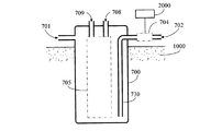
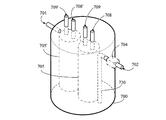
中継用流体貯留ドラム700は、伝導熱材料により構成され、一体型または組立式であり、一種の縦型の中継用流体貯留ドラム状の流体熱交換器である。中継用流体貯留ドラム700は、垂直にまたは下へ斜設する設置方法で自然蓄熱体1000に貼設するか、または全部取り付けまたは一部取り付けるように設置される。流体を出入りさせて対流機能とするように、中継用流体貯留ドラム700には少なくとも一個の第1流体入口701及び少なくとも一個の第1流体出口702が設置される。第1流体入口701は中継用流体貯留ドラム700の低いところに設置され、第1流体出口702は中継用流体貯留ドラム700の高いところに設置され、両者の設置位置が逆であることによって中継用流体貯留ドラム700内部の低いところに流体が停滞することを避ける。
The relay
中継用流体貯留ドラム700を通過する流体は、外力による加圧、または位置の違いによる重力により、または第1流体入口701及び/または第1流体出口702に第1ポンプ704が設置され、人力または制御装置2000により汲み出しまたは汲み入れが制御、すなわち流量を汲み上げまたは停止或いは汲み上げる流量の調整を含む制御により、液体または気体、或いは液体から気体に変化し、または気体から液体に変化するように駆動される流体である。
中継用流体貯留ドラム700の内部には、一個以上の流体対流体の熱交換装置705が設置される。
The fluid passing through the relay
One or more fluid-to-fluid
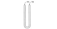
図3は、本発明の第1実施形態に係る熱交換装置705を構成する管路がU型であるときの構成を示す模式図、図4は、本発明の第1実施形態に係る熱交換装置705を構成する管路が螺旋状であるときの構成を示す模式図、図5は、本発明の第1実施形態に係る熱交換装置705を構成する管路が波浪状でるときの構成を示す模式図、図6は、本発明の第1実施形態に係る熱交換装置705を構成するU型管路に伝導熱翼が追加設置された構成を示す模式図である。
FIG. 3 is a schematic diagram showing a configuration when the pipes constituting the
熱交換装置705には、流体を通過させるように独立した流路が具備され、それにより中継用流体貯留ドラム700内部の流体に熱交換が行われる。熱交換装置705は、直接流体管路が、図3から図5に示すようなU型、螺旋状、波状を呈するなど各種の幾何形状を含む管状流路構造により構成され、かつ/または図6に示すように、熱交換装置におけるU管状流路構造に伝導熱翼が追加設置されてもよい。前述各種形状の熱交換装置705の流体管路には第2流体入口708及び第2流体出口709が具備される。
The
熱交換装置705は、直接伝導熱構造体の内部に流路が設置され、また第2流体入口708及び第2流体出口709が具備され、かつ/または伝導熱構造体に伝導熱翼が延設される。図7は、本発明の第1実施形態に係る熱交換装置705において、伝導熱構造体内部に流路が設置される構成を示す模式図である。
熱交換装置705の個別の流体通路には、第2流体入口708及び第2流体出口709が具備される。
The
A separate fluid passage of the
熱交換装置705を通過する流体通路の流体は、外力による加圧、または位置の違いによる重力により、または第1ポンプ704が設置され流体を汲み出しまたは汲み入れることにより、同じまたは異なる液体または気体、或いは液体から気体に変化し、または気体から液体に変化するように個別に駆動される流体である。
制御装置2000は、電力、動力、流力、または磁力を活動力とする制御装置であり、それにより第1ポンプ704が制御され、この制御装置2000は第1ポンプ704が設置されると同時に設置される。
The fluid in the fluid passage that passes through the
The
本発明の第1実施形態による縦型流体熱交換器においては、熱交換装置705を内蔵する円筒状の中継用流体貯留ドラム700は、一個以上であり、二個以上である場合は、その個別の中継用流体貯留ドラム700内部における個別の流体通路は直列、並列、または直並列である。
異なる中継用流体貯留ドラム700は、個別に操作され、個別に同じまたは異なる種類の流体を通過させる。
In the vertical fluid heat exchanger according to the first embodiment of the present invention, the number of the cylindrical relay
Different relay
中継用流体貯留ドラム700の内部には、一つ以上の流路に分けられる流体通路があり、二つ以上の流路に分けられる場合は、各別の流路は個別に流体入口及び流体出口が設置される。
中継用流体貯留ドラム700の内部には、二つ以上の流路を有する流体通路がある場合は、その個別の流体通路は個別に作動し、同じまたは異なる流体を通過させる。
中継用流体貯留ドラム700の内部には、二つ以上の流路を有する流体通路がある場合は、その個別の流体通路は直列、並列、または直並列である。
The relay
If there is a fluid passage having two or more flow paths in the relay
When there is a fluid passage having two or more flow paths in the relay
本発明の第1実施形態による縦型流体熱交換器においては、熱交換装置705は直接少なくとも二つの流路が交差するU形流体管路により構成されてもよく、一つの流体通路には第2流体入口708及び第2流体出口709が具備され、もう一つの流体通路には第3流体入口708’及び第3流体出口709’が具備される。
In the vertical fluid heat exchanger according to the first embodiment of the present invention, the
本発明の第1実施形態による縦型流体熱交換器は、修繕・保守を行わせるために、さらに中継用流体貯留ドラム700内部の高いところに第1流体入口701及び第1流体出口702が設置され、中継用流体貯留ドラム700内部に第1流体入口701及び/または第1流体出口702に連続する内部流体を上下方向へ流れるようにガイドする導流路構造730が設置されてもよく、それにより第1流体入口701から第1流体出口702までの間の流路が中継用流体貯留ドラム700の底部を通過することが確保され、それにより中継用流体貯留ドラム700の基底層の流体が停滞することを避ける。図8は、本発明の第1実施形態に係る中継用流体貯留ドラム700内部の高いところに第1流体入口701及び第1流体出口702が設置され、中継用流体貯留ドラム700内部に第1流体入口701及び/または第1流体出口702に連続する内部の流体を上下方向へ流れるようにガイドする導流路構造730が設置される構成を示す斜視図であり、図9は図8の模式図である。
The vertical fluid heat exchanger according to the first embodiment of the present invention is further provided with a first
(第2実施形態)
本発明の第2実施形態に係る中継用流体貯留ドラム700内部には、一体型熱交換機7050を備える。一体型熱交換機7050の流体通路は、二つ以上の流路のU型管路が並列または平行に互いに重なり合うように設置され、またはある角度をもって交差するように設置される。図10は、本発明の第2実施形態に係る一体型熱交換器を構成するU型管路が二つ90度に交差する構成を示す斜視図である。流体通路が二つ以上の流路を有する場合は、個別の流体通路には流体入口及び流体出口が具備され、個別の流体通路は単独で作動し、個別に同じまたは異なる流体を通過させる。図11は、本発明の第2実施形態に係る中継用流体貯留ドラム内部の一体型熱交換機に二つの流体通路が設置される構成を示す斜視図であり、また図12は図11の模式図である。
中継用流体貯留ドラム700内部の一体型熱交換機7050の流体通路が二つ以上の流路を有する場合は、その個別の流体通路は直列、並列、または直並列である。
(Second Embodiment)
An
When the fluid passage of the
(第3実施形態)
本発明の第3実施形態に係る中継用流体貯留ドラム700内には、二個以上の熱交換装置705、熱交換装置705’が設置される。その場合は、その個別の熱交換装置705の流体通路は、一つ以上の流路を有し、個別の熱交換装置705または熱交換装置705’の流体通路には個別に第2流体入口708または第3流体入口708’及び第2流体出口709または第3流体出口709’が具備され、個別の流体通路は単独で作動し同じまたは異なる流体を通過させる。図13は、本発明の第3実施形態に係る中継用流体貯留ドラム内に二個以上の熱交換装置が設置される構成を示す斜視図であり、図14は図13の模式図である。
(Third embodiment)
Two or more
同じ中継用流体貯留ドラム700内に二個以上の熱交換装置705、熱交換装置705’等が設置される場合は、その個別の熱交換装置705または熱交換装置705’の流体通路は直列、並列、または直並列である。
中継用流体貯留ドラム700内部に設置される異なる熱交換装置705、熱交換装置705’の流体通路は単独で作動する。
When two or more
The fluid passages of different
中継用流体貯留ドラム700内部の異なる熱交換装置705、熱交換装置705’の流体通路は、個別に同じまたは異なる流体を通過させる。
中継用流体貯留ドラム700内部の異なる熱交換装置705、熱交換装置705’の流体通路は、直列、並列、または直並列である。
中継用流体貯留ドラム700において、異なる熱交換装置705、熱交換装置705’を通過する管路の流体は、外力による加圧、または位置の違いによる重力により、または第1ポンプ704が設置され、人力または制御装置2000により汲み出しまたは汲み入れが制御されることにより、液体または気体、或いは液体から気体または気体から液体に変化するように個別に駆動される流体である。
The fluid passages of the different
The fluid passages of the different
In the relay
(第4実施形態)
本発明の第4実施形態に係る熱交換装置705は、その流体通路の第2流体入口708または第2流体出口709に開閉バルブ710が設置される。図15は、本発明の第4実施形態に係る熱交換装置705において、その流体通路の第2流体入口708及び/または第2流体出口709に開閉バルブ710が設置される構成を示す斜視図であり、図16は図15の模式図である。
(Fourth embodiment)
In the
図15、図16に示すように、熱交換装置705の流体通路の第2流体入口708及び/または第2流体出口709に制御バルブ710が設置されることにより、熱交換装置705に入る流体通路の流体が制御され調整される。
本発明の実施形態による縦型流体熱交換器の中継用流体貯留ドラム700において、そのドラム状の断面形状は円形、楕円形、星形、またはその他の形で構成される。
中継用流体貯留ドラム700の形状は、平行棒または平行棒でない形状を含む。
As shown in FIGS. 15 and 16, the fluid passage entering the
In the relay
The shape of the relay
(第5実施形態)
本発明の第5実施形態に係る中継用流体貯留ドラム700は、その第1流体入口701及び/または第1流体出口702に開閉バルブ703が設置される。人力または制御装置2000により開閉バルブ703が制御されることにより開または閉動作を行いまたは流量の調整を操作し、また第1ポンプ704を制御し汲み上げまたは停止、或いは汲み上げる流量を調整する。制御装置2000は電力、動力、流力、または磁力を活動力とする制御装置である。図17は、本発明の第5実施形態に係る中継用流体貯留ドラムにおいて、その第1流体入口701及び/または第1流体出口702に開閉バルブ703が設置される構成を示す斜視図であり、図18は図17の模式図である。
(Fifth embodiment)
The relay
(第6実施形態)
本発明の第6実施形態に係る中継用流体貯留ドラム700は、その第1流体入口701に第1制御バルブ801が設置されかつ/または第1流体出口702に第2制御バルブ802が設置される。また両者の間に支流管路800が設置され、これにより、支流管路を経る流体流量を制御し調整し、それにより中継用流体貯留ドラム700内部に入る流体の流量を調整する。また人力または制御装置2000により第1制御バルブ801及び/または第2制御バルブ802を制御し、開または閉動作を行って流量を調整し、また第1ポンプ704を制御することにより汲み上げまたは停止、或いは汲み上げる流量を調整する。制御装置2000は電力または動力または流力または磁力を活動力とする制御装置である。図19は、本発明の第6実施形態に係る中継用流体貯留ドラムにおいて、第1流体入口701に第1制御バルブ801、かつ/または第1流体出口702に第2制御バルブ802が設置され、また両者の間に支流管路800が設置される構成を示す斜視図であり、図20は図19の模式図である。
(Sixth embodiment)
In the relay
図19及び図20においては、第1制御バルブ801、第2制御バルブ802及び支流管路800によっては以下の一種または一種以上のモードの流動が行われる。
1)支流管路800の流体を遮断し、中継用流体貯留ドラム700を完全に通過させ出入させる。
2)中継用流体貯留ドラム700内部に入る流体を遮断し、支流管路800を完全に通過させ流通させる。
3)一部の流体が中継用流体貯留ドラム700内部を通過し、一部の流体が支流管路800を経る。
4)中継用流体貯留ドラム700内部を通過する流体流量の大小を制御しまた開閉の機能を有する。
19 and 20, depending on the
1) Shut off the fluid in the
2) The fluid that enters the relay
3) A part of the fluid passes through the relay
4) Controls the flow rate of the fluid passing through the relay
本発明の実施形態による縦型流体熱交換器の中継用流体貯留ドラム700及び/又は熱交換装置705は、一体型構造で構成されてもよく、または組立式構造で構成されることにより取外し保守を行うことに寄与する。
本発明の実施形態に係る熱交換装置705は、その構成の断面形状は円形、楕円形、星形、正方形、またはその他の形状により構成される。
本発明の実施形態に係る熱交換装置705はその形状は平行棒の形状または平行棒でない形状を含む。
The relay
The
The
(第7実施形態)
本発明の第7実施形態による縦型流体熱交換器の中継用流体貯留ドラム700には、さらに通気用管路720が設置される。通気用管路720の高さが流体源の高さより高いことにより、流体がこぼれるのを防ぐ。さらに/または通気用開閉バルブ725が設置されることにより、入口から流体が入らない。中継用流体貯留ドラム700内部の流体を第1ポンプ704により汲み出そうとするときには、人工または制御装置2000により通気用開閉バルブ725を操作することにより、第1ポンプ704で中継用流体貯留ドラム700内部の流体を汲み出す時に負圧をなくす。図21は、本発明の第7実施形態に係る中継用流体貯留ドラム700にさらに通気用管路720が設置される構成を示す模式図である。
(Seventh embodiment)
An
(第8実施形態)
本発明の第8実施形態による縦型流体熱交換器はの中継用流体貯留ドラム700には、熱交換装置705、第1流体出口702、第1ポンプ704及び制御装置2000が設置されることに加え、さらに逆流流体出口702’が設置される。逆流流体出口702’と上流の流体管路の間または流体源900との間に、逆流管路750が設置され、また第2ポンプ714が直列で設置される。人力または制御装置2000により第2ポンプ714を制御し、それにより中継用流体貯留ドラム700の一部の流体を逆流管路750を通じて上流に汲み返し、半閉鎖式の熱エネルギーの調整機能を持つシステムとなる。逆流流体出口702’が別途設置され、それが中継用流体貯留ドラム700の高いところにある場合には、中継用流体貯留ドラム700において上下方向へ流れるように内部の流体をガイドする導流路構造730’が追加設置されなければならず、逆流流体出口702’が中継用流体貯留ドラム700の低いところに設置される場合は、上下方向へ流れるように内部の流体をガイドする導流路構造730’が追加設置される必要がない。図22は、本発明の第8実施形態に係る中継用流体貯留ドラム700において、逆流流体出口702’が設置され、また逆流流体出口702’と上流の流体管路との間または流体源900との間に、逆流管路750が設置され、また第2ポンプ714が直列に設置され、それにより中継用流体貯留ドラム700の一部の流体を逆流管路750を通じて上流に汲み返し、さらに半閉鎖式の熱エネルギー調整の機能を有するシステムを示す模式図である。
(Eighth embodiment)
In the relay
(第9実施形態)
本発明の第9実施形態に係る中継用流体貯留ドラム700には、第1ポンプ704及び第1流体出口702を設置せず、熱交換装置705のみが保留される。逆流流体出口702’と上流の流体管路または流体源900との間に逆流管路750が設置され、また第2ポンプ714が直列に設置される。人力または制御装置2000により第2ポンプ714を制御し、それにより中継用流体貯留ドラム700の流体を上流に汲み返し、さらに閉鎖式の熱エネルギーの調整機能を持つシステムとなる。逆流流体出口702’が別途設置され、それが中継用流体貯留ドラム700の高いところにある場合には、中継用流体貯留ドラム700において上下方向へ流れるように内部の流体をガイドする導流路構造730’が追加設置されなければならず、逆流流体出口702’が中継用流体貯留ドラム700の低いところに設置される場合は、上下方向へ流れるように内部の流体をガイドする導流路構造730’が追加設置される必要がない。図23は、本発明の第9実施形態に係る中継用流体貯留ドラム700において、熱交換装置705だけが保留され、逆流流体出口702’と上流の流体管路または流体源900との間に逆流管路750が設置され、また第2ポンプ714が直列に設置され、それにより中継用流体貯留ドラム700の流体を上流に汲み返し、さらに閉鎖式の熱エネルギー調整の機能を有するシステムを示す模式図である。
(Ninth embodiment)
In the relay
(第10実施形態)
本発明の第10実施形態による縦型流体熱交換器は、さらに中継用流体貯留ドラム700より高いところに次段の流体貯留層施設850が設置される。次段の流体貯留層施設850は、第1ポンプ704から汲み上げられ流体管路810を通じて汲み入れられる流体を貯留する。次段の流体貯留層施設850は、半閉鎖式または全閉鎖式の流体末端の貯留層施設であり、かつ/または流体を再流出させる流体口723を有し、かつ/または前述の次段の流体貯留層施設850の天井部に通気用管路720が設置され、かつ/または通気用開閉バルブ725が設置される。図24は、本発明の第10実施形態による縦型流体熱交換器において、中継用流体貯留ドラム700より高いところに次段の流体貯留層施設850が設置されることにより、第1ポンプ704に汲み上げられ、流体管路810を通じて汲み入れられる流体を貯留する構成を示す模式図である。
(10th Embodiment)
In the vertical fluid heat exchanger according to the tenth embodiment of the present invention, the next-stage
人力または制御装置2000により第1ポンプ704を制御することにより汲み上げが行われる場合には、第1ポンプ704から汲み上げられ流体管路810を通じて次段の流体貯留層装置850まで汲み入れる流体を貯留する。次段の流体貯留層施設850は半閉鎖式または全閉鎖式の流体末端の貯留層施設であり、かつ/または流体を再流出させる流体口723を有する。次段の流体貯留層施設850は閉鎖構造または非閉鎖構造であり、かつ/または通気用管路720または通気用開閉バルブ725が設置される。
When pumping is performed by controlling the
また中継用流体貯留ドラム700と次段の流体貯留層施設850との間に第1輔助流体管道820が設置されてもよく、中継用流体貯留ドラム700の通気用管路720に代わる。さらに/または前述流体末端の次段の流体貯留層施設850の天井部に通気用管路720及び/または通気用開閉バルブ725が設置される。図25は、本発明の第10実施形態による縦型流体熱交換器において、さらに中継用流体貯留ドラム700と次段の流体貯留層施設850との間に第1輔助流体管道820が設置される構成を示す模式図である。
A first auxiliary
次段の流体貯留層施設850が閉鎖構造である場合には、中継用流体貯留ドラム700内部の流体が人力または制御装置2000により第1ポンプ704を制御することにより汲み上げられ、中継用流体貯留ドラム700内部の流体が流体管路810を通じて次段の流体貯留層施設850に入る時には、次段の流体貯留層施設850内部の空気が第1輔助流体管道820を通じて中継用流体貯留ドラム700に入り、それによって流体が汲み出され空きスペースが生じる。
When the
(第11実施形態)
本発明の実施形態による縦型流体熱交換器は、さらに空調用冷却塔の直列操作に応用することができ、それにより水塔が冷却された後の水流を直列にし、それが中継用流体貯留ドラム700内部に設置される熱交換装置705の流路を経てから、空調設備まで汲み戻される。図26は、本発明の第11実施形態による縦型流体熱交換器であって、空調用冷却塔の直列操作に応用されるシステムを示す模式図である。図26に基づいて、その主要な構成を以下に説明する。
(Eleventh embodiment)
The vertical fluid heat exchanger according to the embodiment of the present invention can be further applied to the serial operation of the cooling tower for air conditioning, thereby serializing the water flow after the water tower is cooled, which is the fluid storage drum for relay After passing through the flow path of the
本発明の第11実施形態に係る中継用流体貯留ドラム700は、伝導熱材料により構成され、一体型または組立式であり、一種の縦型の中継用流体貯留ドラム状の流体熱交換器である。垂直にまたは下へ斜設する設置方法で自然蓄熱体1000に貼設、全部取り付け、または一部取り付けるように設置される。流体を出入りさせて対流機能となるように、中継用流体貯留ドラム700には少なくとも一個の第1流体入口701及び少なくとも一個の第1流体出口702が設置される。第1流体入口701は、中継用流体貯留ドラム700の低いところに設置され、第1流体出口702は中継用流体貯留ドラム700の高いところに設置される。これにより、両者の設置位置が逆であることによる中継用流体貯留ドラム700内部の低いところに流体が停滞することを避ける。図26に示すように、中継用流体貯留ドラム700内部の高いところに第1流体入口701及び第1流体出口702が設置すると、修繕・保守を行うのに便利である。中継用流体貯留ドラム700内部には、第1流体入口701、及び/または第1流体出口702に連続する上下方向へ流れるように内部流体をガイドする導流路構造730が設置され、それにより第1流体入口701から第1流体出口702までの間の流路が中継用流体貯留ドラム700の底部を通過することが確保される。それにより中継用流体貯留ドラム700の基底層の流体が停滞することを避けることができる。
The relay
中継用流体貯留ドラム700を通過する流体は、外力による加圧、または位置の違いによる重力により、または第1流体入口701及び/または第1流体出口702に第1ポンプ704が設置され、人力または制御装置2000により汲み出しまたは汲み入れが制御されることにより、流量の汲み上げまたは停止または汲み上げる流量が調整され、液体または気体、或いは液体から気体にまたは気体から液体になるように駆動される流体である。
The fluid passing through the relay
熱交換装置705を内蔵する円筒状の中継用流体貯留ドラム700は、一個以上あり、二個以上である場合は、その個別の中継用流体貯留ドラム700の内部の個別の流体通路は直列、並列、または直並列である。
熱交換装置705には、流体を通過させるように独立した流路が具備され、それにより中継用流体貯留ドラム700内部の流体に熱交換が行われ、熱交換装置705の流体管路には第2流体入口708及び第2流体出口709が具備される。
There are one or more cylindrical relay
The
熱交換装置705の個別の流体通路には、第2流体入口708及び第2流体出口709が具備される。
熱交換装置705を通過する流体通路の流体は、外力による加圧、または位置の違いによる重力により、または第2ポンプ714が設置され流体を汲み出しまたは汲み入れることにより、同じまたは異なる液体または気体、或いは液体から気体に変化し、または気体から液体に変化するように個別に駆動される流体である。
A separate fluid passage of the
The fluid in the fluid passage that passes through the
冷却水塔1200は、従来の空調用冷却塔であり、冷却水塔には一つの高温水流入口1201及び冷却水流出口1202を有する。それにより高温水は第1輔助流体管路820を経て熱交換装置705の第2流体入口708を通過してから、第2流体出口709から空調装置1500の熱交換装置を通過し、それから直列で設置されている第3ポンプ724を経て、その高温水を、第2輔助流体管路830を通じて高温水流入口1201まで汲み出して高温水が冷却水塔1200に入る。
The cooling
(第12実施形態)
図27は、本発明の第12実施形態による縦型流体熱交換器であって、空調用冷却塔の直列操作に応用されるもう一つのシステムである。図26に示すように、本発明の第12実施形態に係る中継用流体貯留ドラム700は、直接流体を貯留する状態となっており、それには第1流体入口701及び第1流体出口702を具備する。制御装置2000により第3ポンプ724及び/または通気用開閉バルブ725を制御することにより、第2輔助流体管路830を通じて高温水流入口1201から冷却水塔1200に入るように空調装置1500の熱交換器内部の流体を汲み上げ、流体は冷却水流出口1202から第1輔助流体管道820を通じて第1流体入口701を通過し中継用流体貯留ドラム700に入ってから、第1流体出口702を経て空調装置1500の流体入口に転送される。本発明の第12実施形態に係る中継用流体貯留ドラム700には、熱交換装置705が設置されず、中継用流体貯留ドラム700のケースにより自然蓄熱体に対して熱交換が行われる。
(Twelfth embodiment)
FIG. 27 is a vertical fluid heat exchanger according to a twelfth embodiment of the present invention, which is another system applied to serial operation of cooling towers for air conditioning. As shown in FIG. 26, the relay
(第13実施形態)
本発明の第13実施形態による縦型流体熱交換器は、水中または地層の自然蓄熱体に全部または一部が取付けられている場合に、さらにその中継用流体貯留ドラム700の周りに外導管3000が設置される。外導管3000の内径は中継用流体貯留ドラム700の外径より大きいかまたはそれに等しい。図28は、本発明の第13実施形態に係る中継用流体貯留ドラム700の周りに外導管3000が設置される構成を示す模式図である。その構成について、以下に説明する。
(13th Embodiment)
The vertical fluid heat exchanger according to the thirteenth embodiment of the present invention further includes an
外導管3000は伝導熱材料により構成され、その内径は中継用流体貯留ドラム700の外径より大きいかまたはそれに等しく、その長さは中継用流体貯留ドラム700のそれに等しいかまたそれより長い。
外導管3000と中継用流体貯留ドラム700は直接接触し、両者の間には間隙があり、それにより中継用流体貯留ドラム700を取り付けまた取り出すことができ、または膠状及び/または液体及び/または固体の伝導熱材料を入れることができる。
The
The
(第14実施形態)
本発明の第14実施形態による縦型流体熱交換器は、さらに中継用流体貯留ドラム700が比較的長い二段以上の階段状の構成に製造され、その上段は比較的大きく下段は比較的小さく、円筒状または少なくとも三面の階層を有する柱状構造を呈し、自然蓄熱体との伝熱面積を増加させる。
(14th Embodiment)
In the vertical fluid heat exchanger according to the fourteenth embodiment of the present invention, the relay
図29は、本発明の第14実施形態に係る中継用流体貯留ドラム700を比較的長い二階段状の構成に製造し、その上段のサイズが比較的大きく下段のサイズが比較的小さく、また上段を自然蓄熱体の表面に設置し、下段を自然蓄熱体のなかに設置する構成を示す模式図である。
図29に基づいて、本発明の第14実施形態に係る中継用流体貯留ドラム700の主要な構成及び設置方法を以下に説明する。
FIG. 29 shows that the relay
Based on FIG. 29, the main structure and installation method of the relay
中継用流体貯留ドラム700は伝導熱材料により構成され、上が大きく下が小さい二段以上の階段状の構成を呈し、断面積の比較的大きい上段構造及び断面積の比較的小さい下段構造を有する。中継用流体貯留ドラムの下段7001の垂直な軸方向に沿う断面形状は円形、楕円形、三面または三面以上の多面形により構成される。
中継用流体貯留ドラム700の自然蓄熱体に漏出するケース部分は断熱材料で製造され構成される断熱体760であり、または断熱材料で断熱体760が構成されることにより中継用流体貯留ドラム700の自然蓄熱体に漏出するケースが覆われる。
その設置方法は、上段は自然蓄熱体の表面に置かれ、下段は自然蓄熱体に取付けられる。
The relay
The case portion leaking to the natural heat storage body of the relay
In the installation method, the upper stage is placed on the surface of the natural heat storage body, and the lower stage is attached to the natural heat storage body.
(第15実施形態)
図30は、本発明の第15実施形態に係る中継用流体貯留ドラム700を比較的長い二階段状の構成に製造し、その上段のサイズが比較的大きく下段のサイズが比較的小さく、一部のサイズが比較的大きい上段及びサイズが比較的小さい下段全体を自然蓄熱体に取り付ける構成を示す模式図である。
(Fifteenth embodiment)
FIG. 30 shows a relay
図30に基づいて、本発明の第15実施形態に係る中継用流体貯留ドラム700の主要な構成及び設置方法を以下に説明する。
中継用流体貯留ドラム700は、伝導熱材料により構成され、上が大きく下が小さい二段以上の階段状の構造を呈し、断面積の比較的大きい上段構造及び断面積の比較的小さい下段構造を有する。中継用流体貯留ドラムの下段7001の垂直な軸方向に沿う断面形状は円形、楕円形、三面または三面以上の多面形により構成される。
Based on FIG. 30, the main structure and installation method of the relay
The relay
中継用流体貯留ドラム700の自然蓄熱体に漏出するケース部分は断熱材料で製造され構成される断熱体760である。または断熱材料で断熱体760が構成されることにより中継用流体貯留ドラム700の自然蓄熱体に漏出するケースが覆われる。
その設置方法は、比較的大きい上段の一番上の所は自然蓄熱体に置かれ、残りの比較的大きい上段及び接続された比較的小さい下段全体は自然蓄熱体に取付けられる。
The case portion that leaks to the natural heat storage body of the relay
The installation method is such that the top of the relatively large upper stage is placed on the natural heat storage body, and the remaining relatively large upper stage and the connected relatively small lower stage are attached to the natural heat storage body.
(第16実施形態)
図31は、本発明の第16実施形態に係る中継用流体貯留ドラム700を比較的長い二階段状の構成に製造し、その上段のサイズが比較的大きく下段のサイズが比較的小さく、また高架構造物1100により中継用流体貯留ドラム700のサイズが比較的大きい上段を支持し、サイズが比較的小さ下段を下の自然蓄熱体まで延長させる構成を示す模式図である。
(Sixteenth embodiment)
FIG. 31 shows a relay
図31に基づいて、本発明の第16実施形態に係る中継用流体貯留ドラム700の主要な構成及び設置方法を以下に説明する。
中継用流体貯留ドラム700は伝導熱材料により構成され、上が大きく下が小さい二段以上の階段状の構造を呈し、断面積の比較的大きい上段構造及び断面積の比較的小さい下段構造を有する。中継用流体貯留ドラムの下段7001の垂直な軸方向に沿う断面形状は円形、楕円形、三面または三面以上の多面形により構成される。
Based on FIG. 31, the main structure and installation method of the relay
The relay
中継用流体貯留ドラム700の自然蓄熱体に漏出するケース部分は断熱材料で製造され構成される断熱体760であり、または断熱材料で断熱体760が構成されることにより中継用流体貯留ドラム700の自然蓄熱体に漏出するケースが覆われる。
その設置方法は、高架構造物1100により中継用流体貯留ドラム700の比較的大きい上段を支持し、比較的小さい下段は下の自然蓄熱体に設置される。
The case portion leaking to the natural heat storage body of the relay
As for the installation method, the relatively large upper stage of the relay
(第17実施形態)
本発明の第17実施形態による縦型流体熱交換器は、中継用流体貯留ドラム700の上段が比較的大きく下段が比較的小さい円錐形または少なくとも三面の錐形または台形構造により構成される。
図32は、本発明の第17実施形態に係る中継用流体貯留ドラム700を円錐形に製造した構成を示す斜視図である。
(17th Embodiment)
The vertical fluid heat exchanger according to the seventeenth embodiment of the present invention is configured by a conical shape or an at least three-sided conical or trapezoidal structure in which the upper stage is relatively large and the lower stage is relatively small.
FIG. 32 is a perspective view showing a configuration in which the relay
図32に基づいて、本発明の第17実施形態に係る中継用流体貯留ドラム700の主要な構成及び設置方法を以下に説明する。
中継用流体貯留ドラム700は、伝導熱材料により構成され、上が大きく下が小さい円錐形構造を呈し、断面積の比較的大きい上段構造及び断面積の比較的小さい下段構造を有する。中継用流体貯留ドラム700の垂直な軸方向に沿う断面形状は円形、楕円形により構成される。
Based on FIG. 32, the main configuration and installation method of the relay
The relay
中継用流体貯留ドラム700の自然蓄熱体に漏出するケース部分は断熱材料で製造され構成される断熱体760であり、または断熱材料で断熱体760が構成されることにより中継用流体貯留ドラム700の自然蓄熱体に漏出するケースが覆われる。
その設置方法は、円錐形構造の断面積の比較的大きい部分の上段構造は、自然蓄熱体の表面に置かれ、断面積の比較的小さい下段は自然蓄熱体に取付けられる。
The case portion leaking to the natural heat storage body of the relay
The installation method is such that the upper structure having a relatively large cross-sectional area of the conical structure is placed on the surface of the natural heat storage body, and the lower structure having a relatively small cross-sectional area is attached to the natural heat storage body.
(第18実施形態)
図33は本発明の第18実施形態に係る中継用流体貯留ドラム700を逆角錐形の多面立体構造に製造した構成を示す斜視図である。
図33に基づいて、本発明の第18実施形態に係る中継用流体貯留ドラム700の主要な構成及び設置方法を以下に説明する。
(Eighteenth embodiment)
FIG. 33 is a perspective view showing a configuration in which the relay
Based on FIG. 33, the main structure and installation method of the relay
中継用流体貯留ドラム700は伝導熱材料により構成され、上が大きく下が小さい角錐形の多面立体構造を呈し、断面積の比較的大きい上段構造及び断面積の比較的小さい下段構造を有する。中継用流体貯留ドラム700の垂直な軸方向に沿う断面形状は三面、三面以上の多面形により構成される。
中継用流体貯留ドラム700の自然蓄熱体に漏出するケース部分は断熱材料で製造され構成される断熱体760であり、または断熱材料で断熱体760が構成されることにより中継用流体貯留ドラム700の自然蓄熱体に漏出するケースが覆われる。
その設置方法は、角錐形の多面立体構造の断面積の比較的大きい部分の上段構造は、自然蓄熱体の表面に置かれ、断面積の比較的小さい下段は自然蓄熱体に取付けられる。
The relay
The case portion leaking to the natural heat storage body of the relay
The installation method is such that the upper structure having a relatively large cross-sectional area of the pyramidal polyhedral solid structure is placed on the surface of the natural heat storage body, and the lower structure having a relatively small cross-sectional area is attached to the natural heat storage body.
(第19実施形態)
図34は、本発明の第19実施形態に係る中継用流体貯留ドラム700を逆円錐台形状に製造した構成を示す斜視図である。
図34に基づいて、本発明の第19実施形態に係る中継用流体貯留ドラム700の主要な構成及び設置方法を以下に説明する。
(Nineteenth embodiment)
FIG. 34 is a perspective view showing a configuration in which the relay
Based on FIG. 34, the main structure and installation method of the relay
中継用流体貯留ドラム700は伝導熱材料により構成され、上が大きく下が小さい円錐台形体構造を呈し、断面積の比較的大きい上段構造及び断面積の比較的小さい下段構造を有する。中継用流体貯留ドラム700の垂直な軸方向に沿う断面形状は円形、楕円形により構成される。
中継用流体貯留ドラム700の自然蓄熱体に漏出するケース部分は断熱材料で製造され構成される断熱体760であり、または断熱材料で断熱体760が構成されることにより中継用流体貯留ドラム700の自然蓄熱体に漏出するケースが覆われる。
その設置方法は、円錐台形体状構造の断面積の比較的大きい部分の上段構造は自然蓄熱体の表面に置かれ、断面積の比較的小さい下段は自然蓄熱体に取付けられる。
The relay
The case portion leaking to the natural heat storage body of the relay
The installation method is such that the upper structure having a relatively large cross-sectional area of the truncated cone-shaped structure is placed on the surface of the natural heat storage body, and the lower structure having a relatively small cross-sectional area is attached to the natural heat storage body.
(第20実施形態)
図35は、本発明の第20実施形態に係る中継用流体貯留ドラム700を逆角錐台形状の多面立体構造に製造した構成を示す斜視図である。
図35に基づいて、本発明の第20実施形態に係る中継用流体貯留ドラム700の主要な構成及び設置方法を以下に説明する。
(20th embodiment)
FIG. 35 is a perspective view showing a configuration in which the relay
Based on FIG. 35, the main structure and installation method of the relay
中継用流体貯留ドラム700は伝導熱材料により構成され、上が大きく下が小さい角錐台形の多面立体構造を呈し、断面積の比較的大きい上段構造及び断面積の比較的小さい下段構造を有する。中継用流体貯留ドラム700の垂直な軸方向に沿う断面形状は三面、三面以上の多面形により構成される。
中継用流体貯留ドラム700の自然蓄熱体に漏出するケース部分は断熱材料で製造され構成される断熱体760であり、または断熱材料で断熱体760が構成されることにより中継用流体貯留ドラム700の自然蓄熱体に漏出するケースが覆われる。
その設置方法は、角錐台形の多面立体構造の断面積の比較的大きい部分の上段構造は自然蓄熱体の表面に置かれ、断面積の比較的小さい下段は自然蓄熱体に取付けられる。
The relay
The case portion leaking to the natural heat storage body of the relay
As for the installation method, the upper structure of the portion having a relatively large cross-sectional area of the truncated pyramidal polyhedral structure is placed on the surface of the natural heat storage body, and the lower structure having a relatively small cross-sectional area is attached to the natural heat storage body.
700・・・中継用流体貯留ドラム
701・・・第1流体入口
702・・・第1流体出口
702’・・・逆流流体出口
703・・・開閉バルブ
704・・・第1ポンプ
705・・・熱交換装置
708・・・第2流体入口
708’・・・第3流体入口
709・・・第2流体出口
709’・・・第3流体出口
710・・・制御バルブ
714・・・第2ポンプ
720・・・通気用管路
723・・・流体口
724・・・第3ポンプ
725・・・通気用開閉バルブ
730・・・導流路構造
730’・・・導流路構造
750・・・逆流管路
760・・・断熱体
800・・・支流管路
801・・・第1制御バルブ
802・・・第2制御バルブ
810・・・流体管路
820・・・第1輔助流体管道
830・・・第2輔助流体管道
850・・・次段の流体貯留層施設
900・・・流体源
1000・・・自然蓄熱体
1100・・・高架構造物
1200・・・冷却水塔
1201・・・高温水流入口
1202・・・冷却水流出口
1500・・・空調装置
2000・・・制御装置
3000・・・外導管
7001・・・中継用流体貯留ドラム下段
7050・・・一体型熱交換機
700 ... Relay
Claims (5)
前記流体熱交換器には、少なくとも一個の流体入口及び少なくとも一個の流体出口が設置されており、前記流体熱交換器には、浅層地表における蓄熱体の補助貯水タンクとして機能するために、外部に流れる熱伝導流体を一時的に保存し、中継用流体貯留ドラム状の構造内部に熱交換装置が設けられ、前記熱交換装置には前記熱伝導流体を流通させるように、少なくとも一つの流体管路が設けられ、前記熱伝導流体と前記流体熱交換器内の流体と熱交換が行われ、前記流体熱交換器における流体は、浅層地表の土壌、湖、川、海、池、人工貯水池、または、人工的に設置された流体槽の流体貯留層の人工施設の熱エネルギーと熱交換が行われる自然蓄熱体に設置される縦型流体熱交換器であって、
前記流体熱交換器としての中継用流体貯留ドラム(700)は、伝導熱材料により構成される一体型または組立式であり、一種の縦型の中継用流体貯留ドラム状の流体熱交換器であり、垂直または下へ斜設する設置方法で前記自然蓄熱体(1000)に貼設するか、または全部取り付けるか、または一部取り付けるように設置され、流体を出入りさせる対流機能となるように、少なくとも一個の第1流体入口(701)及び少なくとも一個の第1流体出口(702)が設置され、前記第1流体入口(701)は前記中継用流体貯留ドラム(700)の低いところに設置され、前記第1流体出口(702)は前記中継用流体貯留ドラム(700)の高いところに設置され、または両者の設置位置が逆であることにより、前記中継用流体貯留ドラム(700)の内部の低いところに流体が停滞することを避け、
前記中継用流体貯留ドラム(700)を通過する流体は、外力による加圧、または位置の違いによる重力により、前記第1流体入口(701)及び前記第1流体出口(702)の少なくとも一方に第1ポンプ(704)が設置され、人力または制御装置(2000)により汲み出しまたは汲み入れが制御されることにより、流量を汲み上げまたは停止させ、汲み上げる流量を調整することにより、液体または気体を駆動し、液体から気体に、または気体から液体になるように流体を駆動し、
前記中継用流体貯留ドラム(700)の内部には、一個以上の流体対流体の熱交換装置(705)が設置され、
前記熱交換装置(705)には流体を通過させるように独立した流路が具備され、前記中継用流体貯留ドラム(700)内部の流体に熱交換が行われ、前記熱交換装置(705)は直接流体管路がU型、螺旋状、波状を呈する各種の幾何形状の管状流路構造により構成され、かつ前記熱交換装置におけるU管状流路構造に伝導熱翼が追加設置され、各種形状の前記熱交換装置(705)の流体管路には第2流体入口(708)及び第2流体出口(709)が具備され、
前記熱交換装置(705)は、直接伝導熱構造体の内部に流路が設置され、また前記第2流体入口(708)及び前記第2流体出口(709)が具備され、かつ伝導熱構造体に伝導熱翼が延設され、
前記熱交換装置(705)の個別の流体通路には、前記第2流体入口及び前記第2流体出口が具備され、
前記熱交換装置(705)を通過する流体通路の流体は、外力による加圧または位置の違いによる重力により、第1ポンプ(704)が設置され、流体を汲み出しまたは汲み入れることにより、同じまたは異なる液体または気体、或いは液体から気体に変化し、または気体から液体に変化するように個別に駆動される流体であり、
前記制御装置(2000)は、電力、動力、流力、または磁力を活動力とする制御装置であり、前記第1ポンプ(704)を制御し、前記第1ポンプ(704)が設置されると同時に設置され、
前記熱交換装置(705)を内蔵する円筒状の前記中継用流体貯留ドラム(700)は、一個以上であり、二個以上である場合は、個別の前記中継用流体貯留ドラム(700)内部における個別の流体通路は直列、並列、または直並列であり、異なる前記中継用流体貯留ドラム(700)は、個別に操作し、個別に同じまたは異なる種類の流体を通過させ、
前記中継用流体貯留ドラム(700)の内部には、一つ以上の流路に分けられる流体通路があり、二つ以上の流路に分けられる場合は、各別の流路は個別に流体入口及び流体出口が設置され、
前記中継用流体貯留ドラム(700)の内部に、二つ以上の流路を有する流体通路がある場合は、その個別の流体通路は個別に作動し、同じまたは異なる流体を通過させ、
前記中継用流体貯留ドラム(700)の内部に、二つ以上の流路を有する流体通路がある場合は、その個別の流体通路は直列または並列または直並列であり、
前記中継用流体貯留ドラム(700)は、前記第1流体入口(701)に第1制御バルブ(801)が設置され、または前記第1流体出口(702)に第2制御バルブ(802)が設置され、また前記第1制御バルブ(801)及び第2制御バルブ(802)の間に支流管路(800)が設置されて、前記支流管路(800)を経る流体流量を制御し調整することにより、前記中継用流体貯留ドラム(700)内部に入る流体の流量を調整し、また人力または前記制御装置(2000)により前記第1制御バルブ(801)及び前記第2制御バルブ(802)の少なくとも一方を制御し、開または閉動作を行って流量を調整し、また前記第1ポンプ(704)を制御することにより汲み上げまたは停止、或いは汲み上げる流量を調整し、前記制御装置(2000)は電力、動力、流力、または磁力を活動力とする制御装置であり、前記第1制御バルブ(801)、前記第2制御バルブ(802)、及び前記支流管路(800)によって、
前記支流管路(800)の流体を遮断し前記中継用流体貯留ドラム(700)を完全に通過させ出入するモード、
前記中継用流体貯留ドラム(700)内部に入る流体を遮断し、流体が前記支流管路(800)を完全に通過し流通するモード、
一部の流体が前記中継用流体貯留ドラム(700)内部を通過し、一部が前記支流管路(800)を経るモード、
前記中継用流体貯留ドラム(700)の内部を通過する流体流量の大小を制御し、また開閉の機能を有するモード、のうちの一種以上のモードの流動が行われることを特徴とする縦型流体熱交換器。 A vertical relay fluid storage drum-like fluid heat exchanger that can be either a shallow surface soil, lake, river, sea, pond, artificial reservoir, or artificially installed fluid reservoir Vertical fluid installed in a natural heat storage body that is installed in a natural heat storage facility and is attached to a natural heat storage body in a vertical or slanted installation method, or is attached to the whole or a part of it. A heat exchanger,
The fluid heat exchanger has at least one fluid inlet and at least one fluid outlet, and the fluid heat exchanger has an external storage tank to function as an auxiliary water storage tank for a heat storage body on a shallow surface. At least one fluid pipe for temporarily storing the heat transfer fluid flowing through the heat transfer device, wherein a heat exchange device is provided inside the relay fluid storage drum-like structure, and the heat transfer fluid is circulated through the heat exchange device. A path is provided to exchange heat between the heat transfer fluid and the fluid in the fluid heat exchanger, and the fluid in the fluid heat exchanger is a soil, lake, river, sea, pond, artificial reservoir on a shallow surface Or a vertical fluid heat exchanger installed in a natural heat storage body that performs heat exchange with the thermal energy of the artificial facility of the fluid reservoir of the artificially installed fluid tank,
The relay fluid storage drum (700) as the fluid heat exchanger is an integral type or assembly type composed of a conductive heat material, and is a kind of vertical fluid storage drum-like fluid heat exchanger. At least in order to provide a convection function to allow the fluid to enter and exit from the natural heat storage body (1000) by being installed vertically or obliquely, or to be attached to all or part of the natural heat storage body (1000). One first fluid inlet (701) and at least one first fluid outlet (702) are installed, and the first fluid inlet (701) is installed at a low position of the relay fluid storage drum (700), and The first fluid outlet (702) is installed at a high position of the relay fluid storage drum (700), or the installation position of both is reversed, so that the relay fluid storage drum is Avoid fluid stagnates at low internal (700),
The fluid passing through the relay fluid storage drum (700) is supplied to at least one of the first fluid inlet (701) and the first fluid outlet (702) by pressurization by an external force or gravity by a difference in position. 1 pump (704) is installed, pumping or pumping is controlled by human power or control device (2000), pumping or stopping the flow rate, adjusting the pumping flow rate to drive liquid or gas, Driving fluids from liquid to gas, or from gas to liquid,
Inside the relay fluid storage drum (700), one or more fluid-to-fluid heat exchange devices (705) are installed,
The heat exchange device (705) is provided with an independent flow path for allowing fluid to pass therethrough, heat is exchanged with the fluid inside the relay fluid storage drum (700), and the heat exchange device (705) The direct fluid conduit is composed of tubular flow channel structures of various shapes that are U-shaped, spiral, and wavy, and conductive heat blades are additionally installed in the U tubular flow channel structure of the heat exchange device, The fluid line of the heat exchange device (705) includes a second fluid inlet (708) and a second fluid outlet (709),
The heat exchanging device (705) has a flow path installed inside a direct heat conduction structure, and is provided with the second fluid inlet (708) and the second fluid outlet (709), and the heat conduction structure. The conduction heat blade is extended to
The individual fluid passages of the heat exchange device (705) include the second fluid inlet and the second fluid outlet,
The fluid in the fluid passage passing through the heat exchange device (705) is the same or different when the first pump (704) is installed by pumping or pumping the fluid by pressurization due to external force or gravity due to a difference in position. Liquid or gas, or fluid that is individually driven to change from liquid to gas, or from gas to liquid,
The control device (2000) is a control device that uses electric power, power, fluid force, or magnetic force as an active force, and controls the first pump (704), and when the first pump (704) is installed. Installed at the same time,
There are one or more cylindrical relay fluid storage drums (700) containing the heat exchange device (705), and when there are two or more, the relay fluid storage drums (700) inside the individual relay fluid storage drums (700). The individual fluid passages are in series, parallel, or series-parallel, and the different relay fluid storage drums (700) operate individually and individually pass the same or different types of fluids,
The relay fluid storage drum (700) has a fluid passage divided into one or more flow paths. When the relay fluid storage drum (700) is divided into two or more flow paths, each separate flow path is individually a fluid inlet. And a fluid outlet is installed,
When there is a fluid passage having two or more flow paths inside the relay fluid storage drum (700), the individual fluid passages individually operate to pass the same or different fluids,
The inside of the relay fluid storage barrel (700), if there is a fluid passage having two or more channels, the individual fluid passageway Ri in series or parallel or series-parallel der,
In the relay fluid storage drum (700), a first control valve (801) is installed at the first fluid inlet (701), or a second control valve (802) is installed at the first fluid outlet (702). A branch flow line (800) is installed between the first control valve (801) and the second control valve (802) to control and adjust the fluid flow rate through the branch flow line (800). The flow rate of the fluid entering the relay fluid storage drum (700) is adjusted by at least one of the first control valve (801) and the second control valve (802) by human power or the control device (2000). One is controlled, the flow is adjusted by performing an opening or closing operation, and the pumping or stopping is controlled by controlling the first pump (704). The control device (2000) is a control device that uses electric power, power, flow force, or magnetic force as an active force, and includes the first control valve (801), the second control valve (802), and the branch flow line (800). )
A mode in which the fluid in the tributary pipe (800) is shut off and completely passes through the relay fluid storage drum (700);
A mode in which the fluid entering the relay fluid storage drum (700) is shut off, and the fluid completely passes through the tributary conduit (800);
A mode in which a part of the fluid passes through the relay fluid storage drum (700) and a part of the fluid passes through the branch pipe (800);
Vertical characterized by Rukoto controls fluid flow magnitude passing inside and mode having the function of opening and closing, the flow of one or more modes of the conducted of the relay fluid storage barrel (700) Fluid heat exchanger.
前記流体熱交換器には、少なくとも一個の流体入口及び少なくとも一個の流体出口が設置されており、前記流体熱交換器には、浅層地表における蓄熱体の補助貯水タンクとして機能するために、外部に流れる熱伝導流体を一時的に保存し、中継用流体貯留ドラム状の構造内部に熱交換装置が設けられ、前記熱交換装置には前記熱伝導流体を流通させるように、少なくとも一つの流体管路が設けられ、前記熱伝導流体と前記流体熱交換器内の流体と熱交換が行われ、前記流体熱交換器における流体は、浅層地表の土壌、湖、川、海、池、人工貯水池、または、人工的に設置された流体槽の流体貯留層の人工施設の熱エネルギーと熱交換が行われる自然蓄熱体に設置される縦型流体熱交換器であって、
前記流体熱交換器としての中継用流体貯留ドラム(700)は、伝導熱材料により構成される一体型または組立式であり、一種の縦型の中継用流体貯留ドラム状の流体熱交換器であり、垂直または下へ斜設する設置方法で前記自然蓄熱体(1000)に貼設するか、または全部取り付けるか、または一部取り付けるように設置され、流体を出入りさせる対流機能となるように、少なくとも一個の第1流体入口(701)及び少なくとも一個の第1流体出口(702)が設置され、前記第1流体入口(701)は前記中継用流体貯留ドラム(700)の低いところに設置され、前記第1流体出口(702)は前記中継用流体貯留ドラム(700)の高いところに設置され、または両者の設置位置が逆であることにより、前記中継用流体貯留ドラム(700)の内部の低いところに流体が停滞することを避け、
前記中継用流体貯留ドラム(700)を通過する流体は、外力による加圧、または位置の違いによる重力により、前記第1流体入口(701)及び前記第1流体出口(702)の少なくとも一方に第1ポンプ(704)が設置され、人力または制御装置(2000)により汲み出しまたは汲み入れが制御されることにより、流量を汲み上げまたは停止させ、汲み上げる流量を調整することにより、液体または気体を駆動し、液体から気体に、または気体から液体になるように流体を駆動し、
前記中継用流体貯留ドラム(700)の内部には、一個以上の流体対流体の熱交換装置(705)が設置され、
前記熱交換装置(705)には流体を通過させるように独立した流路が具備され、前記中継用流体貯留ドラム(700)内部の流体に熱交換が行われ、前記熱交換装置(705)は直接流体管路がU型、螺旋状、波状を呈する各種の幾何形状の管状流路構造により構成され、かつ前記熱交換装置におけるU管状流路構造に伝導熱翼が追加設置され、各種形状の前記熱交換装置(705)の流体管路には第2流体入口(708)及び第2流体出口(709)が具備され、
前記熱交換装置(705)は、直接伝導熱構造体の内部に流路が設置され、また前記第2流体入口(708)及び前記第2流体出口(709)が具備され、かつ伝導熱構造体に伝導熱翼が延設され、
前記熱交換装置(705)の個別の流体通路には、前記第2流体入口及び前記第2流体出口が具備され、
前記熱交換装置(705)を通過する流体通路の流体は、外力による加圧または位置の違いによる重力により、第1ポンプ(704)が設置され、流体を汲み出しまたは汲み入れることにより、同じまたは異なる液体または気体、或いは液体から気体に変化し、または気体から液体に変化するように個別に駆動される流体であり、
前記制御装置(2000)は、電力、動力、流力、または磁力を活動力とする制御装置であり、前記第1ポンプ(704)を制御し、前記第1ポンプ(704)が設置されると同時に設置され、
前記熱交換装置(705)を内蔵する円筒状の前記中継用流体貯留ドラム(700)は、一個以上であり、二個以上である場合は、個別の前記中継用流体貯留ドラム(700)内部における個別の流体通路は直列、並列、または直並列であり、異なる前記中継用流体貯留ドラム(700)は、個別に操作し、個別に同じまたは異なる種類の流体を通過させ、
前記中継用流体貯留ドラム(700)の内部には、一つ以上の流路に分けられる流体通路があり、二つ以上の流路に分けられる場合は、各別の流路は個別に流体入口及び流体出口が設置され、
前記中継用流体貯留ドラム(700)の内部に、二つ以上の流路を有する流体通路がある場合は、その個別の流体通路は個別に作動し、同じまたは異なる流体を通過させ、
前記中継用流体貯留ドラム(700)の内部に、二つ以上の流路を有する流体通路がある場合は、その個別の流体通路は直列または並列または直並列であり、
前記中継用流体貯留ドラム(700)には、前記熱交換装置(705)、前記第1流体出口(702)、前記第1ポンプ(704)及び前記制御装置(2000)が設置されることに加え、
さらに逆流流体出口(702')が設置され、また前記逆流流体出口(702')と上流の流体管路の間または流体源(900)との間に、逆流管路(750)が設置され、また前記第2ポンプ(714)が直列で設置され、人力または前記制御装置(2000)により前記第2ポンプ(714)を制御することにより、前記中継用流体貯留ドラム(700)の一部の流体を前記逆流管路(750)を通じて上流に汲み返し、半閉鎖式の熱エネルギーの調整機能を持つシステムとなり、
前記逆流流体出口(702')が別途設置されて前記中継用流体貯留ドラム(700)の高いところにある場合には、前記中継用流体貯留ドラム(700)において上下方向へ流れるように内部の流体をガイドする導流路構造(730')が追加設置されなければならず、前記逆流流体出口(702')が前記中継用流体貯留ドラム(700)の低いところに設置される場合は、上下方向へ流れるように内部の流体をガイドする前記導流路構造(730')が追加設置される必要がないことを特徴とする縦型流体熱交換器。 A vertical relay fluid storage drum-like fluid heat exchanger that can be either a shallow surface soil, lake, river, sea, pond, artificial reservoir, or artificially installed fluid reservoir Vertical fluid installed in a natural heat storage body that is installed in a natural heat storage facility and is attached to a natural heat storage body in a vertical or slanted installation method, or is attached to the whole or a part of it. A heat exchanger,
The fluid heat exchanger has at least one fluid inlet and at least one fluid outlet, and the fluid heat exchanger has an external storage tank to function as an auxiliary water storage tank for a heat storage body on a shallow surface. At least one fluid pipe for temporarily storing the heat transfer fluid flowing through the heat transfer device, wherein a heat exchange device is provided inside the relay fluid storage drum-like structure, and the heat transfer fluid is circulated through the heat exchange device. A path is provided to exchange heat between the heat transfer fluid and the fluid in the fluid heat exchanger, and the fluid in the fluid heat exchanger is a soil, lake, river, sea, pond, artificial reservoir on a shallow surface Or a vertical fluid heat exchanger installed in a natural heat storage body that performs heat exchange with the thermal energy of the artificial facility of the fluid reservoir of the artificially installed fluid tank,
The relay fluid storage drum (700) as the fluid heat exchanger is an integral type or assembly type composed of a conductive heat material, and is a kind of vertical fluid storage drum-like fluid heat exchanger. At least in order to provide a convection function to allow the fluid to enter and exit from the natural heat storage body (1000) by being installed vertically or obliquely, or to be attached to all or part of the natural heat storage body (1000). One first fluid inlet (701) and at least one first fluid outlet (702) are installed, and the first fluid inlet (701) is installed at a low position of the relay fluid storage drum (700), and The first fluid outlet (702) is installed at a high position of the relay fluid storage drum (700), or the installation position of both is reversed, so that the relay fluid storage drum is Avoid fluid stagnates at low internal (700),
The fluid passing through the relay fluid storage drum (700) is supplied to at least one of the first fluid inlet (701) and the first fluid outlet (702) by pressurization by an external force or gravity by a difference in position. 1 pump (704) is installed, pumping or pumping is controlled by human power or control device (2000), pumping or stopping the flow rate, adjusting the pumping flow rate to drive liquid or gas, Driving fluids from liquid to gas, or from gas to liquid,
Inside the relay fluid storage drum (700), one or more fluid-to-fluid heat exchange devices (705) are installed,
The heat exchange device (705) is provided with an independent flow path for allowing fluid to pass therethrough, heat is exchanged with the fluid inside the relay fluid storage drum (700), and the heat exchange device (705) The direct fluid conduit is composed of tubular flow channel structures of various shapes that are U-shaped, spiral, and wavy, and conductive heat blades are additionally installed in the U tubular flow channel structure of the heat exchange device, The fluid line of the heat exchange device (705) includes a second fluid inlet (708) and a second fluid outlet (709),
The heat exchanging device (705) has a flow path installed inside a direct heat conduction structure, and is provided with the second fluid inlet (708) and the second fluid outlet (709), and the heat conduction structure. The conduction heat blade is extended to
The individual fluid passages of the heat exchange device (705) include the second fluid inlet and the second fluid outlet,
The fluid in the fluid passage passing through the heat exchange device (705) is the same or different when the first pump (704) is installed by pumping or pumping the fluid by pressurization due to external force or gravity due to a difference in position. Liquid or gas, or fluid that is individually driven to change from liquid to gas, or from gas to liquid,
The control device (2000) is a control device that uses electric power, power, fluid force, or magnetic force as an active force, and controls the first pump (704), and when the first pump (704) is installed. Installed at the same time,
There are one or more cylindrical relay fluid storage drums (700) containing the heat exchange device (705), and when there are two or more, the relay fluid storage drums (700) inside the individual relay fluid storage drums (700). The individual fluid passages are in series, parallel, or series-parallel, and the different relay fluid storage drums (700) operate individually and individually pass the same or different types of fluids,
The relay fluid storage drum (700) has a fluid passage divided into one or more flow paths. When the relay fluid storage drum (700) is divided into two or more flow paths, each separate flow path is individually a fluid inlet. And a fluid outlet is installed,
When there is a fluid passage having two or more flow paths inside the relay fluid storage drum (700), the individual fluid passages individually operate to pass the same or different fluids,
When there is a fluid passage having two or more flow paths inside the relay fluid storage drum (700), the individual fluid passages are in series, parallel, or series-parallel,
The relay fluid storage drum (700) includes the heat exchange device (705), the first fluid outlet (702), the first pump (704), and the control device (2000). ,
Further, a backflow fluid outlet (702 ′) is installed, and a backflow line (750) is installed between the backflow fluid outlet (702 ′) and the upstream fluid line or the fluid source (900), Further, the second pump (714) is installed in series, and the second pump (714) is controlled by human power or the control device (2000), whereby a part of the fluid in the relay fluid storage drum (700) is obtained. Is pumped back to the upstream through the backflow pipe (750) and becomes a system having a semi-closed heat energy adjustment function,
When the backflow fluid outlet (702 ′) is separately installed and is located at a high position on the relay fluid storage drum (700), the internal fluid flows upward and downward in the relay fluid storage drum (700). When the backflow fluid outlet (702 ′) is installed at a low position of the relay fluid storage drum (700), it is necessary to install a guide channel structure (730 ′) for guiding vertical fluid heat exchanger wherein the guide channel structure for guiding the fluid inside (730 ') is you characterized in that there is no need to be additionally installed to flow into.
前記流体熱交換器には、少なくとも一個の流体入口及び少なくとも一個の流体出口が設置されており、前記流体熱交換器には、浅層地表における蓄熱体の補助貯水タンクとして機能するために、外部に流れる熱伝導流体を一時的に保存し、中継用流体貯留ドラム状の構造内部に熱交換装置が設けられ、前記熱交換装置には前記熱伝導流体を流通させるように、少なくとも一つの流体管路が設けられ、前記熱伝導流体と前記流体熱交換器内の流体と熱交換が行われ、前記流体熱交換器における流体は、浅層地表の土壌、湖、川、海、池、人工貯水池、または、人工的に設置された流体槽の流体貯留層の人工施設の熱エネルギーと熱交換が行われる自然蓄熱体に設置される縦型流体熱交換器であって、
前記流体熱交換器としての中継用流体貯留ドラム(700)は、伝導熱材料により構成される一体型または組立式であり、一種の縦型の中継用流体貯留ドラム状の流体熱交換器であり、垂直または下へ斜設する設置方法で前記自然蓄熱体(1000)に貼設するか、または全部取り付けるか、または一部取り付けるように設置され、流体を出入りさせる対流機能となるように、少なくとも一個の第1流体入口(701)及び少なくとも一個の第1流体出口(702)が設置され、前記第1流体入口(701)は前記中継用流体貯留ドラム(700)の低いところに設置され、前記第1流体出口(702)は前記中継用流体貯留ドラム(700)の高いところに設置され、または両者の設置位置が逆であることにより、前記中継用流体貯留ドラム(700)の内部の低いところに流体が停滞することを避け、
前記中継用流体貯留ドラム(700)を通過する流体は、外力による加圧、または位置の違いによる重力により、前記第1流体入口(701)及び前記第1流体出口(702)の少なくとも一方に第1ポンプ(704)が設置され、人力または制御装置(2000)により汲み出しまたは汲み入れが制御されることにより、流量を汲み上げまたは停止させ、汲み上げる流量を調整することにより、液体または気体を駆動し、液体から気体に、または気体から液体になるように流体を駆動し、
前記中継用流体貯留ドラム(700)の内部には、一個以上の流体対流体の熱交換装置(705)が設置され、
前記熱交換装置(705)には流体を通過させるように独立した流路が具備され、前記中継用流体貯留ドラム(700)内部の流体に熱交換が行われ、前記熱交換装置(705)は直接流体管路がU型、螺旋状、波状を呈する各種の幾何形状の管状流路構造により構成され、かつ前記熱交換装置におけるU管状流路構造に伝導熱翼が追加設置され、各種形状の前記熱交換装置(705)の流体管路には第2流体入口(708)及び第2流体出口(709)が具備され、
前記熱交換装置(705)は、直接伝導熱構造体の内部に流路が設置され、また前記第2流体入口(708)及び前記第2流体出口(709)が具備され、かつ伝導熱構造体に伝導熱翼が延設され、
前記熱交換装置(705)の個別の流体通路には、前記第2流体入口及び前記第2流体出口が具備され、
前記熱交換装置(705)を通過する流体通路の流体は、外力による加圧または位置の違いによる重力により、第1ポンプ(704)が設置され、流体を汲み出しまたは汲み入れることにより、同じまたは異なる液体または気体、或いは液体から気体に変化し、または気体から液体に変化するように個別に駆動される流体であり、
前記制御装置(2000)は、電力、動力、流力、または磁力を活動力とする制御装置であり、前記第1ポンプ(704)を制御し、前記第1ポンプ(704)が設置されると同時に設置され、
前記熱交換装置(705)を内蔵する円筒状の前記中継用流体貯留ドラム(700)は、一個以上であり、二個以上である場合は、個別の前記中継用流体貯留ドラム(700)内部における個別の流体通路は直列、並列、または直並列であり、異なる前記中継用流体貯留ドラム(700)は、個別に操作し、個別に同じまたは異なる種類の流体を通過させ、
前記中継用流体貯留ドラム(700)の内部には、一つ以上の流路に分けられる流体通路があり、二つ以上の流路に分けられる場合は、各別の流路は個別に流体入口及び流体出口が設置され、
前記中継用流体貯留ドラム(700)の内部に、二つ以上の流路を有する流体通路がある場合は、その個別の流体通路は個別に作動し、同じまたは異なる流体を通過させ、
前記中継用流体貯留ドラム(700)の内部に、二つ以上の流路を有する流体通路がある場合は、その個別の流体通路は直列または並列または直並列であり、
前記中継用流体貯留ドラム(700)には前記第1ポンプ(704)及び前記第1流体出口(702)が設置されず、前記熱交換装置(705)のみが保留され、逆流流体出口(702')と上流の流体管路または流体源(900)との間に逆流管路(750)が設置され、また前記第2ポンプ(714)が直列に設置され、人力または前記制御装置(2000)により前記第2ポンプ(714)を制御することにより、前記中継用流体貯留ドラム(700)の流体を上流に汲み返し、閉鎖式の熱エネルギーの調整機能を持つシステムとなり、
前記逆流流体出口(702')が別途設置されて前記中継用流体貯留ドラム(700)の高いところにある場合には、前記中継用流体貯留ドラム(700)において上下方向へ流れるように内部の流体をガイドする導流路構造(730')が追加設置されなければならず、前記逆流流体出口(702')が前記中継用流体貯留ドラム(700)の低いところに設置される場合は、上下方向へ流れるように内部の流体をガイドする前記導流路構造(730')が追加設置される必要がないことを特徴とする縦型流体熱交換器。 A vertical relay fluid storage drum-like fluid heat exchanger that can be either a shallow surface soil, lake, river, sea, pond, artificial reservoir, or artificially installed fluid reservoir Vertical fluid installed in a natural heat storage body that is installed in a natural heat storage facility and is attached to a natural heat storage body in a vertical or slanted installation method, or is attached to the whole or a part of it. A heat exchanger,
The fluid heat exchanger has at least one fluid inlet and at least one fluid outlet, and the fluid heat exchanger has an external storage tank to function as an auxiliary water storage tank for a heat storage body on a shallow surface. At least one fluid pipe for temporarily storing the heat transfer fluid flowing through the heat transfer device, wherein a heat exchange device is provided inside the relay fluid storage drum-like structure, and the heat transfer fluid is circulated through the heat exchange device. A path is provided to exchange heat between the heat transfer fluid and the fluid in the fluid heat exchanger, and the fluid in the fluid heat exchanger is a soil, lake, river, sea, pond, artificial reservoir on a shallow surface Or a vertical fluid heat exchanger installed in a natural heat storage body that performs heat exchange with the thermal energy of the artificial facility of the fluid reservoir of the artificially installed fluid tank,
The relay fluid storage drum (700) as the fluid heat exchanger is an integral type or assembly type composed of a conductive heat material, and is a kind of vertical fluid storage drum-like fluid heat exchanger. At least in order to provide a convection function to allow the fluid to enter and exit from the natural heat storage body (1000) by being installed vertically or obliquely, or to be attached to all or part of the natural heat storage body (1000). One first fluid inlet (701) and at least one first fluid outlet (702) are installed, and the first fluid inlet (701) is installed at a low position of the relay fluid storage drum (700), and The first fluid outlet (702) is installed at a high position of the relay fluid storage drum (700), or the installation position of both is reversed, so that the relay fluid storage drum is Avoid fluid stagnates at low internal (700),
The fluid passing through the relay fluid storage drum (700) is supplied to at least one of the first fluid inlet (701) and the first fluid outlet (702) by pressurization by an external force or gravity by a difference in position. 1 pump (704) is installed, pumping or pumping is controlled by human power or control device (2000), pumping or stopping the flow rate, adjusting the pumping flow rate to drive liquid or gas, Driving fluids from liquid to gas, or from gas to liquid,
Inside the relay fluid storage drum (700), one or more fluid-to-fluid heat exchange devices (705) are installed,
The heat exchange device (705) is provided with an independent flow path for allowing fluid to pass therethrough, heat is exchanged with the fluid inside the relay fluid storage drum (700), and the heat exchange device (705) The direct fluid conduit is composed of tubular flow channel structures of various shapes that are U-shaped, spiral, and wavy, and conductive heat blades are additionally installed in the U tubular flow channel structure of the heat exchange device, The fluid line of the heat exchange device (705) includes a second fluid inlet (708) and a second fluid outlet (709),
The heat exchanging device (705) has a flow path installed inside a direct heat conduction structure, and is provided with the second fluid inlet (708) and the second fluid outlet (709), and the heat conduction structure. The conduction heat blade is extended to
The individual fluid passages of the heat exchange device (705) include the second fluid inlet and the second fluid outlet,
The fluid in the fluid passage passing through the heat exchange device (705) is the same or different when the first pump (704) is installed by pumping or pumping the fluid by pressurization due to external force or gravity due to a difference in position. Liquid or gas, or fluid that is individually driven to change from liquid to gas, or from gas to liquid,
The control device (2000) is a control device that uses electric power, power, fluid force, or magnetic force as an active force, and controls the first pump (704), and when the first pump (704) is installed. Installed at the same time,
There are one or more cylindrical relay fluid storage drums (700) containing the heat exchange device (705), and when there are two or more, the relay fluid storage drums (700) inside the individual relay fluid storage drums (700). The individual fluid passages are in series, parallel, or series-parallel, and the different relay fluid storage drums (700) operate individually and individually pass the same or different types of fluid,
The relay fluid storage drum (700) has a fluid passage divided into one or more flow paths. When the relay fluid storage drum (700) is divided into two or more flow paths, each separate flow path is individually a fluid inlet. And a fluid outlet is installed,
When there is a fluid passage having two or more flow paths inside the relay fluid storage drum (700), the individual fluid passages individually operate to pass the same or different fluids,
When there is a fluid passage having two or more flow paths inside the relay fluid storage drum (700), the individual fluid passages are in series, parallel, or series-parallel,
The relay fluid storage drum (700) is not provided with the first pump (704) and the first fluid outlet (702), and only the heat exchange device (705) is reserved, and the reverse flow fluid outlet (702 ′) ) And an upstream fluid line or fluid source (900), a reverse flow line (750) is installed, and the second pump (714) is installed in series by human power or the control device (2000). By controlling the second pump (714), the fluid of the relay fluid storage drum (700) is pumped up upstream, and the system has a closed type thermal energy adjustment function,
When the backflow fluid outlet (702 ′) is separately installed and is located at a high position on the relay fluid storage drum (700), the internal fluid flows upward and downward in the relay fluid storage drum (700). When the backflow fluid outlet (702 ′) is installed at a low position of the relay fluid storage drum (700), it is necessary to install a guide channel structure (730 ′) for guiding vertical fluid heat exchanger wherein the guide channel structure for guiding the fluid inside (730 ') is you characterized in that there is no need to be additionally installed to flow into.
前記流体熱交換器には、少なくとも一個の流体入口及び少なくとも一個の流体出口が設置されており、前記流体熱交換器には、浅層地表における蓄熱体の補助貯水タンクとして機能するために、外部に流れる熱伝導流体を一時的に保存し、中継用流体貯留ドラム状の構造内部に熱交換装置が設けられ、前記熱交換装置には前記熱伝導流体を流通させるように、少なくとも一つの流体管路が設けられ、前記熱伝導流体と前記流体熱交換器内の流体と熱交換が行われ、前記流体熱交換器における流体は、浅層地表の土壌、湖、川、海、池、人工貯水池、または、人工的に設置された流体槽の流体貯留層の人工施設の熱エネルギーと熱交換が行われる自然蓄熱体に設置される縦型流体熱交換器であって、
前記流体熱交換器としての中継用流体貯留ドラム(700)は、伝導熱材料により構成される一体型または組立式であり、一種の縦型の中継用流体貯留ドラム状の流体熱交換器であり、垂直または下へ斜設する設置方法で前記自然蓄熱体(1000)に貼設するか、または全部取り付けるか、または一部取り付けるように設置され、流体を出入りさせる対流機能となるように、少なくとも一個の第1流体入口(701)及び少なくとも一個の第1流体出口(702)が設置され、前記第1流体入口(701)は前記中継用流体貯留ドラム(700)の低いところに設置され、前記第1流体出口(702)は前記中継用流体貯留ドラム(700)の高いところに設置され、または両者の設置位置が逆であることにより、前記中継用流体貯留ドラム(700)の内部の低いところに流体が停滞することを避け、
前記中継用流体貯留ドラム(700)を通過する流体は、外力による加圧、または位置の違いによる重力により、前記第1流体入口(701)及び前記第1流体出口(702)の少なくとも一方に第1ポンプ(704)が設置され、人力または制御装置(2000)により汲み出しまたは汲み入れが制御されることにより、流量を汲み上げまたは停止させ、汲み上げる流量を調整することにより、液体または気体を駆動し、液体から気体に、または気体から液体になるように流体を駆動し、
前記中継用流体貯留ドラム(700)の内部には、一個以上の流体対流体の熱交換装置(705)が設置され、
前記熱交換装置(705)には流体を通過させるように独立した流路が具備され、前記中継用流体貯留ドラム(700)内部の流体に熱交換が行われ、前記熱交換装置(705)は直接流体管路がU型、螺旋状、波状を呈する各種の幾何形状の管状流路構造により構成され、かつ前記熱交換装置におけるU管状流路構造に伝導熱翼が追加設置され、各種形状の前記熱交換装置(705)の流体管路には第2流体入口(708)及び第2流体出口(709)が具備され、
前記熱交換装置(705)は、直接伝導熱構造体の内部に流路が設置され、また前記第2流体入口(708)及び前記第2流体出口(709)が具備され、かつ伝導熱構造体に伝導熱翼が延設され、
前記熱交換装置(705)の個別の流体通路には、前記第2流体入口及び前記第2流体出口が具備され、
前記熱交換装置(705)を通過する流体通路の流体は、外力による加圧または位置の違いによる重力により、第1ポンプ(704)が設置され、流体を汲み出しまたは汲み入れることにより、同じまたは異なる液体または気体、或いは液体から気体に変化し、または気体から液体に変化するように個別に駆動される流体であり、
前記制御装置(2000)は、電力、動力、流力、または磁力を活動力とする制御装置であり、前記第1ポンプ(704)を制御し、前記第1ポンプ(704)が設置されると同時に設置され、
前記熱交換装置(705)を内蔵する円筒状の前記中継用流体貯留ドラム(700)は、一個以上であり、二個以上である場合は、個別の前記中継用流体貯留ドラム(700)内部における個別の流体通路は直列、並列、または直並列であり、異なる前記中継用流体貯留ドラム(700)は、個別に操作し、個別に同じまたは異なる種類の流体を通過させ、
前記中継用流体貯留ドラム(700)の内部には、一つ以上の流路に分けられる流体通路があり、二つ以上の流路に分けられる場合は、各別の流路は個別に流体入口及び流体出口が設置され、
前記中継用流体貯留ドラム(700)の内部に、二つ以上の流路を有する流体通路がある場合は、その個別の流体通路は個別に作動し、同じまたは異なる流体を通過させ、
前記中継用流体貯留ドラム(700)の内部に、二つ以上の流路を有する流体通路がある場合は、その個別の流体通路は直列または並列または直並列であり、
さらに前記中継用流体貯留ドラム(700)を比較的長い二段以上の階段状の構成に製造し、階段状の構造の上段は比較的大きく下段は比較的小さく、円筒状または少なくとも三面の階層を有する柱状構造を呈し、自然蓄熱体との伝熱面積を増加させ、
前記中継用流体貯留ドラム(700)の主要な構成及び設置方法において、
前記中継用流体貯留ドラム(700)は、伝導熱材料により構成され、上が大きく下が小さい二段以上の階段状の構造を呈し、断面積の比較的大きい上段構造及び断面積の比較的小さい下段構造であり、中継用流体貯留ドラムの下段(7001)の垂直な軸方向に沿う断面形状は円形、楕円形、或いは三面または三面以上の多面形により構成され、
前記中継用流体貯留ドラム(700)の前記自然蓄熱体(1000)に漏出するケース部分は断熱材料で製造され構成される断熱体(760)であり、または断熱材料で前記断熱体(760)が構成されることにより前記中継用流体貯留ドラム(700)の前記自然蓄熱体(1000)に漏出するケースが覆われ、
設置方法は、上段が前記自然蓄熱体(1000)の表面に設置され、下段は前記自然蓄熱体(1000)に設置されるか、または比較的大きい上段の一番上の所は前記自然蓄熱体(1000)に置かれ、残りの比較的大きい上段及び接続された比較的小さい下段全体は前記自然蓄熱体(1000)に取付けられるか、または高架構造物(1100)により前記中継用流体貯留ドラム(700)の比較的大きい上段を支持し、比較的小さい下段は下の前記自然蓄熱体(1000)に設置されることを特徴とする縦型流体熱交換器。 A vertical relay fluid storage drum-like fluid heat exchanger that can be either a shallow surface soil, lake, river, sea, pond, artificial reservoir, or artificially installed fluid reservoir Vertical fluid installed in a natural heat storage body that is installed in a natural heat storage facility and is attached to a natural heat storage body in a vertical or slanted installation method, or is attached to the whole or a part of it. A heat exchanger,
The fluid heat exchanger has at least one fluid inlet and at least one fluid outlet, and the fluid heat exchanger has an external storage tank to function as an auxiliary water storage tank for a heat storage body on a shallow surface. At least one fluid pipe for temporarily storing the heat transfer fluid flowing through the heat transfer device, wherein a heat exchange device is provided inside the relay fluid storage drum-like structure, and the heat transfer fluid is circulated through the heat exchange device. A path is provided to exchange heat between the heat transfer fluid and the fluid in the fluid heat exchanger, and the fluid in the fluid heat exchanger is a soil, lake, river, sea, pond, artificial reservoir on a shallow surface Or a vertical fluid heat exchanger installed in a natural heat storage body that performs heat exchange with the thermal energy of the artificial facility of the fluid reservoir of the artificially installed fluid tank,
The relay fluid storage drum (700) as the fluid heat exchanger is an integral type or assembly type composed of a conductive heat material, and is a kind of vertical fluid storage drum-like fluid heat exchanger. At least in order to provide a convection function to allow the fluid to enter and exit from the natural heat storage body (1000) by being installed vertically or obliquely, or to be attached to all or part of the natural heat storage body (1000). One first fluid inlet (701) and at least one first fluid outlet (702) are installed, and the first fluid inlet (701) is installed at a low position of the relay fluid storage drum (700), and The first fluid outlet (702) is installed at a high position of the relay fluid storage drum (700), or the installation position of both is reversed, so that the relay fluid storage drum is Avoid fluid stagnates at low internal (700),
The fluid passing through the relay fluid storage drum (700) is supplied to at least one of the first fluid inlet (701) and the first fluid outlet (702) by pressurization by an external force or gravity by a difference in position. 1 pump (704) is installed, pumping or pumping is controlled by human power or control device (2000), pumping or stopping the flow rate, adjusting the pumping flow rate to drive liquid or gas, Driving fluids from liquid to gas, or from gas to liquid,
Inside the relay fluid storage drum (700), one or more fluid-to-fluid heat exchange devices (705) are installed,
The heat exchange device (705) is provided with an independent flow path for allowing fluid to pass therethrough, heat is exchanged with the fluid inside the relay fluid storage drum (700), and the heat exchange device (705) The direct fluid conduit is composed of tubular flow channel structures of various shapes that are U-shaped, spiral, and wavy, and conductive heat blades are additionally installed in the U tubular flow channel structure of the heat exchange device, The fluid line of the heat exchange device (705) includes a second fluid inlet (708) and a second fluid outlet (709),
The heat exchanging device (705) has a flow path installed inside a direct heat conduction structure, and is provided with the second fluid inlet (708) and the second fluid outlet (709), and the heat conduction structure. The conduction heat blade is extended to
The individual fluid passages of the heat exchange device (705) include the second fluid inlet and the second fluid outlet,
The fluid in the fluid passage passing through the heat exchange device (705) is the same or different when the first pump (704) is installed by pumping or pumping the fluid by pressurization due to external force or gravity due to a difference in position. Liquid or gas, or fluid that is individually driven to change from liquid to gas, or from gas to liquid,
The control device (2000) is a control device that uses electric power, power, fluid force, or magnetic force as an active force, and controls the first pump (704), and when the first pump (704) is installed. Installed at the same time,
There are one or more cylindrical relay fluid storage drums (700) containing the heat exchange device (705), and when there are two or more, the relay fluid storage drums (700) inside the individual relay fluid storage drums (700). The individual fluid passages are in series, parallel, or series-parallel, and the different relay fluid storage drums (700) operate individually and individually pass the same or different types of fluids,
The relay fluid storage drum (700) has a fluid passage divided into one or more flow paths. When the relay fluid storage drum (700) is divided into two or more flow paths, each separate flow path is individually a fluid inlet. And a fluid outlet is installed,
When there is a fluid passage having two or more flow paths inside the relay fluid storage drum (700), the individual fluid passages individually operate to pass the same or different fluids,
When there is a fluid passage having two or more flow paths inside the relay fluid storage drum (700), the individual fluid passages are in series, parallel, or series-parallel,
Further, the relay fluid storage drum (700) is manufactured to have a relatively long stepped structure of two or more steps, the upper step of the stepped structure is relatively large and the lower step is relatively small, and has a cylindrical shape or at least three levels. Presents a columnar structure, increases the heat transfer area with the natural heat storage,
In the main configuration and installation method of the relay fluid storage drum (700),
The relay fluid storage drum 700 is made of a conductive heat material, has a stepped structure of two or more steps with a large top and a small bottom, an upper structure with a relatively large cross-sectional area, and a relatively small cross-sectional area. It is a lower stage structure, and the cross-sectional shape along the vertical axial direction of the lower stage (7001) of the relay fluid storage drum is constituted by a circle, an ellipse, or a polyhedron having three or more faces.
The case part leaking to the natural heat storage body (1000) of the relay fluid storage drum (700) is a heat insulator (760) manufactured and configured with a heat insulating material, or the heat insulator (760) is formed of a heat insulating material. A case that leaks to the natural heat storage body (1000) of the relay fluid storage drum (700) is covered by being configured,
As for the installation method, the upper stage is installed on the surface of the natural heat storage body (1000), the lower stage is installed on the natural heat storage body (1000), or the uppermost part of the relatively large upper stage is the natural heat storage body. The remaining relatively large upper stage and the connected relatively small lower stage are attached to the natural heat storage body (1000) or the relay fluid storage drum (1100) by an elevated structure (1100). supporting a relatively large upper 700), a relatively small lower stage vertical fluid heat exchanger you characterized in that it is installed in the natural thermal energy body below (1000).
前記流体熱交換器には、少なくとも一個の流体入口及び少なくとも一個の流体出口が設置されており、前記流体熱交換器には、浅層地表における蓄熱体の補助貯水タンクとして機能するために、外部に流れる熱伝導流体を一時的に保存し、中継用流体貯留ドラム状の構造内部に熱交換装置が設けられ、前記熱交換装置には前記熱伝導流体を流通させるように、少なくとも一つの流体管路が設けられ、前記熱伝導流体と前記流体熱交換器内の流体と熱交換が行われ、前記流体熱交換器における流体は、浅層地表の土壌、湖、川、海、池、人工貯水池、または、人工的に設置された流体槽の流体貯留層の人工施設の熱エネルギーと熱交換が行われる自然蓄熱体に設置される縦型流体熱交換器であって、
前記流体熱交換器としての中継用流体貯留ドラム(700)は、伝導熱材料により構成される一体型または組立式であり、一種の縦型の中継用流体貯留ドラム状の流体熱交換器であり、垂直または下へ斜設する設置方法で前記自然蓄熱体(1000)に貼設するか、または全部取り付けるか、または一部取り付けるように設置され、流体を出入りさせる対流機能となるように、少なくとも一個の第1流体入口(701)及び少なくとも一個の第1流体出口(702)が設置され、前記第1流体入口(701)は前記中継用流体貯留ドラム(700)の低いところに設置され、前記第1流体出口(702)は前記中継用流体貯留ドラム(700)の高いところに設置され、または両者の設置位置が逆であることにより、前記中継用流体貯留ドラム(700)の内部の低いところに流体が停滞することを避け、
前記中継用流体貯留ドラム(700)を通過する流体は、外力による加圧、または位置の違いによる重力により、前記第1流体入口(701)及び前記第1流体出口(702)の少なくとも一方に第1ポンプ(704)が設置され、人力または制御装置(2000)により汲み出しまたは汲み入れが制御されることにより、流量を汲み上げまたは停止させ、汲み上げる流量を調整することにより、液体または気体を駆動し、液体から気体に、または気体から液体になるように流体を駆動し、
前記中継用流体貯留ドラム(700)の内部には、一個以上の流体対流体の熱交換装置(705)が設置され、
前記熱交換装置(705)には流体を通過させるように独立した流路が具備され、前記中継用流体貯留ドラム(700)内部の流体に熱交換が行われ、前記熱交換装置(705)は直接流体管路がU型、螺旋状、波状を呈する各種の幾何形状の管状流路構造により構成され、かつ前記熱交換装置におけるU管状流路構造に伝導熱翼が追加設置され、各種形状の前記熱交換装置(705)の流体管路には第2流体入口(708)及び第2流体出口(709)が具備され、
前記熱交換装置(705)は、直接伝導熱構造体の内部に流路が設置され、また前記第2流体入口(708)及び前記第2流体出口(709)が具備され、かつ伝導熱構造体に伝導熱翼が延設され、
前記熱交換装置(705)の個別の流体通路には、前記第2流体入口及び前記第2流体出口が具備され、
前記熱交換装置(705)を通過する流体通路の流体は、外力による加圧または位置の違いによる重力により、第1ポンプ(704)が設置され、流体を汲み出しまたは汲み入れることにより、同じまたは異なる液体または気体、或いは液体から気体に変化し、または気体から液体に変化するように個別に駆動される流体であり、
前記制御装置(2000)は、電力、動力、流力、または磁力を活動力とする制御装置であり、前記第1ポンプ(704)を制御し、前記第1ポンプ(704)が設置されると同時に設置され、
前記熱交換装置(705)を内蔵する円筒状の前記中継用流体貯留ドラム(700)は、一個以上であり、二個以上である場合は、個別の前記中継用流体貯留ドラム(700)内部における個別の流体通路は直列、並列、または直並列であり、異なる前記中継用流体貯留ドラム(700)は、個別に操作し、個別に同じまたは異なる種類の流体を通過させ、
前記中継用流体貯留ドラム(700)の内部には、一つ以上の流路に分けられる流体通路があり、二つ以上の流路に分けられる場合は、各別の流路は個別に流体入口及び流体出口が設置され、
前記中継用流体貯留ドラム(700)の内部に、二つ以上の流路を有する流体通路がある場合は、その個別の流体通路は個別に作動し、同じまたは異なる流体を通過させ、
前記中継用流体貯留ドラム(700)の内部に、二つ以上の流路を有する流体通路がある場合は、その個別の流体通路は直列または並列または直並列であり、
前記中継用流体貯留ドラム(700)の上段が比較的大きく下段が比較的小さい円錐形、少なくとも三面の錐形、または台形構造により構成され、
前記中継用流体貯留ドラム(700)を円錐形に製造するか、または前記中継用流体貯留ドラム(700)を逆角錐形の多面立体構造に製造するか、または前記中継用流体貯留ドラム(700)を逆円錐台形状に製造するか、または前記中継用流体貯留ドラム(700)を逆角錐台形状の多面立体構造に製造し、
前記中継用流体貯留ドラム(700)の前記自然蓄熱体(1000)に漏出するケース部分は断熱材料で製造され構成される断熱体(760)であり、または断熱材料で断熱体(760)が構成されることにより前記中継用流体貯留ドラム(700)の前記自然蓄熱体(1000)に漏出するケースが覆われ、
設置方法は、円錐または角錐を含む円錐形構造の断面積の比較的大きい部分の上段構造が、前記自然蓄熱体(1000)の表面に置かれ、断面積の比較的小さい下段は前記自然蓄熱体(1000)に取付けられることを特徴とする縦型流体熱交換器。 A vertical relay fluid storage drum-like fluid heat exchanger that can be either a shallow surface soil, lake, river, sea, pond, artificial reservoir, or artificially installed fluid reservoir Vertical fluid installed in a natural heat storage body that is installed in a natural heat storage facility and is attached to a natural heat storage body in a vertical or slanted installation method, or is attached to the whole or a part of it. A heat exchanger,
The fluid heat exchanger has at least one fluid inlet and at least one fluid outlet, and the fluid heat exchanger has an external storage tank to function as an auxiliary water storage tank for a heat storage body on a shallow surface. At least one fluid pipe for temporarily storing the heat transfer fluid flowing through the heat transfer device, wherein a heat exchange device is provided inside the relay fluid storage drum-like structure, and the heat transfer fluid is circulated through the heat exchange device. A path is provided to exchange heat between the heat transfer fluid and the fluid in the fluid heat exchanger, and the fluid in the fluid heat exchanger is a soil, lake, river, sea, pond, artificial reservoir on a shallow surface Or a vertical fluid heat exchanger installed in a natural heat storage body that performs heat exchange with the thermal energy of the artificial facility of the fluid reservoir of the artificially installed fluid tank,
The relay fluid storage drum (700) as the fluid heat exchanger is an integral type or assembly type composed of a conductive heat material, and is a kind of vertical fluid storage drum-like fluid heat exchanger. At least in order to provide a convection function to allow the fluid to enter and exit from the natural heat storage body (1000) by being installed vertically or obliquely, or to be attached to all or part of the natural heat storage body (1000). One first fluid inlet (701) and at least one first fluid outlet (702) are installed, and the first fluid inlet (701) is installed at a low position of the relay fluid storage drum (700), and The first fluid outlet (702) is installed at a high position of the relay fluid storage drum (700), or the installation position of both is reversed, so that the relay fluid storage drum is Avoid fluid stagnates at low internal (700),
The fluid passing through the relay fluid storage drum (700) is supplied to at least one of the first fluid inlet (701) and the first fluid outlet (702) by pressurization by an external force or gravity by a difference in position. 1 pump (704) is installed, pumping or pumping is controlled by human power or control device (2000), pumping or stopping the flow rate, adjusting the pumping flow rate to drive liquid or gas, Driving fluids from liquid to gas, or from gas to liquid,
Inside the relay fluid storage drum (700), one or more fluid-to-fluid heat exchange devices (705) are installed,
The heat exchange device (705) is provided with an independent flow path for allowing fluid to pass therethrough, heat is exchanged with the fluid inside the relay fluid storage drum (700), and the heat exchange device (705) The direct fluid conduit is composed of tubular flow channel structures of various shapes that are U-shaped, spiral, and wavy, and conductive heat blades are additionally installed in the U tubular flow channel structure of the heat exchange device, The fluid line of the heat exchange device (705) includes a second fluid inlet (708) and a second fluid outlet (709),
The heat exchanging device (705) has a flow path installed inside a direct heat conduction structure, and is provided with the second fluid inlet (708) and the second fluid outlet (709), and the heat conduction structure. The conduction heat blade is extended to
The individual fluid passages of the heat exchange device (705) include the second fluid inlet and the second fluid outlet,
The fluid in the fluid passage passing through the heat exchange device (705) is the same or different when the first pump (704) is installed by pumping or pumping the fluid by pressurization due to external force or gravity due to a difference in position. Liquid or gas, or fluid that is individually driven to change from liquid to gas, or from gas to liquid,
The control device (2000) is a control device that uses electric power, power, fluid force, or magnetic force as an active force, and controls the first pump (704), and when the first pump (704) is installed. Installed at the same time,
There are one or more cylindrical relay fluid storage drums (700) containing the heat exchange device (705), and when there are two or more, the relay fluid storage drums (700) inside the individual relay fluid storage drums (700). The individual fluid passages are in series, parallel, or series-parallel, and the different relay fluid storage drums (700) operate individually and individually pass the same or different types of fluids,
The relay fluid storage drum (700) has a fluid passage divided into one or more flow paths. When the relay fluid storage drum (700) is divided into two or more flow paths, each separate flow path is individually a fluid inlet. And a fluid outlet is installed,
When there is a fluid passage having two or more flow paths inside the relay fluid storage drum (700), the individual fluid passages individually operate to pass the same or different fluids,
When there is a fluid passage having two or more flow paths inside the relay fluid storage drum (700), the individual fluid passages are in series, parallel, or series-parallel,
The relay fluid storage drum (700) has a conical shape in which an upper stage is relatively large and a lower stage is relatively small, a cone shape of at least three faces, or a trapezoidal structure,
The relay fluid storage drum (700) is manufactured in a conical shape, or the relay fluid storage drum (700) is manufactured in an inverted pyramid-shaped polyhedral structure, or the relay fluid storage drum (700). Are manufactured in an inverted truncated cone shape, or the relay fluid storage drum (700) is manufactured in an inverted truncated pyramid shaped polyhedral structure,
The case portion leaking to the natural heat storage body (1000) of the relay fluid storage drum (700) is a heat insulator (760) made of a heat insulating material, or the heat insulator (760) is formed of a heat insulating material. The case where the relay fluid storage drum (700) leaks to the natural heat storage body (1000) is covered,
In the installation method, the upper structure having a relatively large cross-sectional area of a conical structure including a cone or a pyramid is placed on the surface of the natural heat storage body (1000), and the lower structure having a relatively small cross-sectional area is the natural heat storage body. vertical fluid heat exchanger you characterized in that it is attached to (1000).
Applications Claiming Priority (3)
| Application Number | Priority Date | Filing Date | Title |
|---|---|---|---|
| US12/591,024 | 2009-11-05 | ||
| US12/591,024 US9587890B2 (en) | 2009-11-05 | 2009-11-05 | Vertical fluid heat exchanger installed within natural thermal energy body |
| CN200910212362.6A CN102162703B (en) | 2009-11-05 | 2009-11-06 | Vertical fluid heat exchanger put in fluid with normal temperature |
Related Child Applications (1)
| Application Number | Title | Priority Date | Filing Date |
|---|---|---|---|
| JP2015084173A Division JP6046764B2 (en) | 2009-11-05 | 2015-04-16 | Vertical fluid heat exchanger |
Publications (2)
| Publication Number | Publication Date |
|---|---|
| JP2011099668A JP2011099668A (en) | 2011-05-19 |
| JP5736149B2 true JP5736149B2 (en) | 2015-06-17 |
Family
ID=51135867
Family Applications (1)
| Application Number | Title | Priority Date | Filing Date |
|---|---|---|---|
| JP2010248414A Active JP5736149B2 (en) | 2009-11-05 | 2010-11-05 | Vertical fluid heat exchanger |
Country Status (9)
| Country | Link |
|---|---|
| US (1) | US9587890B2 (en) |
| EP (2) | EP2320187B1 (en) |
| JP (1) | JP5736149B2 (en) |
| CN (3) | CN102162703B (en) |
| AU (2) | AU2010241272B2 (en) |
| CA (1) | CA2719815C (en) |
| DE (1) | DE202010015153U1 (en) |
| SG (1) | SG170722A1 (en) |
| TW (2) | TWI534401B (en) |
Cited By (1)
| Publication number | Priority date | Publication date | Assignee | Title |
|---|---|---|---|---|
| JP2015158354A (en) * | 2009-11-05 | 2015-09-03 | 楊 泰和 | Vertical type fluid heat exchanger |
Families Citing this family (27)
| Publication number | Priority date | Publication date | Assignee | Title |
|---|---|---|---|---|
| US11015870B2 (en) * | 2006-10-23 | 2021-05-25 | Ralph Muscatell | Water tank for use in an air-conditioning or heating system |
| GB2450754B8 (en) | 2007-07-06 | 2013-02-06 | Greenfield Energy Ltd | Geothermal energy system and method of operation |
| GB2450755B (en) | 2007-07-06 | 2012-02-29 | Greenfield Energy Ltd | Geothermal energy system and method of operation |
| GB2461029B (en) * | 2008-06-16 | 2011-10-26 | Greenfield Energy Ltd | Thermal energy system and method of operation |
| US9587890B2 (en) * | 2009-11-05 | 2017-03-07 | Tai-Her Yang | Vertical fluid heat exchanger installed within natural thermal energy body |
| GB2488797A (en) | 2011-03-08 | 2012-09-12 | Greenfield Master Ipco Ltd | Thermal Energy System and Method of Operation |
| NO332707B1 (en) | 2011-06-09 | 2012-12-17 | Nest As | Thermal energy storage and plant, method and use thereof |
| CN202915560U (en) * | 2011-07-25 | 2013-05-01 | 杨泰和 | Closed path type temperature uniformizing device |
| US20130042997A1 (en) * | 2011-08-15 | 2013-02-21 | Tai-Her Yang | Open-loopnatural thermal energy releasing system wtih partialreflux |
| EP2647924B1 (en) * | 2012-04-05 | 2021-01-06 | International Merger & Acquisition Corporation | Geothermal heat probe |
| NO337357B1 (en) * | 2012-06-28 | 2016-03-29 | Nest As | Plant for energy production |
| DE202012103717U1 (en) | 2012-09-27 | 2012-12-14 | Viessmann Kältetechnik AG | Thermal storage for refrigeration systems |
| NO339952B1 (en) | 2014-12-19 | 2017-02-20 | Energynest As | Thermal energy storage and heat exchanger |
| NO340371B1 (en) * | 2014-12-19 | 2017-04-10 | Energynest As | HIGH TEMPERATURE THERMAL ENERGY STORAGE, PROCEDURE FOR BUILDING AND PROCEDURE FOR OPERATION OF THIS STOCK |
| DE102016000176A1 (en) * | 2016-01-13 | 2017-07-13 | Alexander Schackert | heat exchanger device |
| EP3327399B2 (en) | 2016-11-23 | 2023-02-15 | Siemens Gamesa Renewable Energy A/S | Method for operating a heat exchange system with a bypass duct and heat exchange system with a bypass duct |
| EP3327398A1 (en) | 2016-11-23 | 2018-05-30 | Siemens Aktiengesellschaft | Heat exchange system with a cooling device and method for ex-changing heat by using the heat exchange system |
| CN107990760A (en) * | 2017-12-30 | 2018-05-04 | 肖英佳 | The anhydrous domestic radiator of safety |
| DE102018109846B4 (en) * | 2018-04-24 | 2020-11-19 | Heinrich Graucob | Process for storing electrical energy |
| CN108709328B (en) * | 2018-05-30 | 2019-12-13 | 浙江大学宁波理工学院 | Geothermal energy pile in static drilling root planting method and heat transfer pipe embedding method thereof |
| DE102019118223A1 (en) * | 2019-07-05 | 2021-01-07 | Envola GmbH | Device for energy transmission and energy storage in a liquid reservoir |
| DE102019133712B3 (en) * | 2019-12-10 | 2021-03-11 | Envola GmbH | Arrangement and method for installing an energy storage device that is at least partially sunk in the ground |
| WO2021116272A1 (en) | 2019-12-10 | 2021-06-17 | Envola GmbH | Assembly and method for installing an energy store, which is at least partially sunk in the ground |
| CN111238279B (en) * | 2020-01-09 | 2021-06-01 | 东南大学 | Relay stable heat release method of heat storage system based on characteristics of fluid transverse heat storage rod bundle thermocline |
| CN112060979B (en) * | 2020-08-21 | 2022-03-29 | 东风汽车集团有限公司 | Cooling control method and device for fuel cell vehicle |
| US20220299010A1 (en) * | 2021-01-19 | 2022-09-22 | Hc Properties Inc | Ground heat exchanger and wind turbine |
| CA3121345C (en) * | 2021-01-19 | 2023-06-27 | Hc Properties Inc. | Ground heat exchanger |
Family Cites Families (51)
| Publication number | Priority date | Publication date | Assignee | Title |
|---|---|---|---|---|
| US2487863A (en) * | 1946-07-01 | 1949-11-15 | Phillips Petroleum Co | Tank car unloading system |
| US3092972A (en) * | 1958-10-22 | 1963-06-11 | Union Carbide Corp | Light weight liquid helium control system |
| US3805885A (en) * | 1970-06-18 | 1974-04-23 | Huisen A Van | Earth heat energy displacement and recovery system |
| US3874174A (en) * | 1974-05-06 | 1975-04-01 | Clarence Kirk Greene | Geothermal heat exchange method and apparatus |
| US4134273A (en) * | 1977-04-22 | 1979-01-16 | Brautigam Robert F | Home heating and cooling system |
| JPS53150948U (en) * | 1977-05-06 | 1978-11-28 | ||
| US4375831A (en) * | 1980-06-30 | 1983-03-08 | Downing Jr James E | Geothermal storage heating and cooling system |
| DE3109850A1 (en) * | 1981-03-14 | 1982-09-30 | Robert Bosch Gmbh, 7000 Stuttgart | CONTROL VALVE |
| US4566532A (en) * | 1981-03-30 | 1986-01-28 | Megatech Corporation | Geothermal heat transfer |
| US4392531A (en) * | 1981-10-09 | 1983-07-12 | Ippolito Joe J | Earth storage structural energy system and process for constructing a thermal storage well |
| US4489568A (en) * | 1982-02-03 | 1984-12-25 | Snyder General Corporation | Ground water heat pump system |
| US4516629A (en) * | 1982-04-06 | 1985-05-14 | Thermal Concepts, Inc. | Earth-type heat exchanger for heat pump system |
| JPS59175887U (en) * | 1983-05-11 | 1984-11-24 | ミサワホ−ム株式会社 | heat storage device |
| US4570851A (en) * | 1984-05-07 | 1986-02-18 | Cirillo John R | Temperature regulating, pressure relief flow valves employing shaped memory alloys |
| JPS60185134U (en) * | 1984-05-16 | 1985-12-07 | 東京電力株式会社 | heat exchange equipment |
| GB2160306B (en) * | 1984-06-14 | 1987-12-09 | Total Energy Conservation And | Method of geothermal energy recovery |
| US4993483A (en) * | 1990-01-22 | 1991-02-19 | Charles Harris | Geothermal heat transfer system |
| US5152153A (en) * | 1991-04-15 | 1992-10-06 | Hsiao Zu C | Air-conditioner/refrigerator cooling water circulating system with underground heat dissipating and hot water recovery sub-system |
| GB2275766B (en) * | 1993-03-02 | 1997-09-10 | Yang Tai Her | An open-cycle air supply and temperature regulation system |
| JP2639633B2 (en) * | 1994-11-02 | 1997-08-13 | 轟産業株式会社 | Reaction heat control mechanism of heat exchange area control type in chemical reactor |
| JP2946082B2 (en) * | 1995-06-14 | 1999-09-06 | 昭己 洲澤 | Method and apparatus for measuring exchange heat of underground heat exchanger |
| US6585036B2 (en) * | 1995-09-12 | 2003-07-01 | Enlink Geoenergy Services, Inc. | Energy systems |
| US6253837B1 (en) * | 1998-03-23 | 2001-07-03 | Long Manufacturing Ltd. | By-pass values for heat exchanger |
| JP2000009352A (en) * | 1998-06-19 | 2000-01-14 | Sanzo Sakamoto | Ground heat extractor |
| JP2000292082A (en) * | 1999-04-07 | 2000-10-20 | Hitachi Plant Eng & Constr Co Ltd | Underground heat storage system |
| US6935569B2 (en) * | 2001-08-31 | 2005-08-30 | Huron, Inc. | Oil cooler bypass valve |
| US6860855B2 (en) * | 2001-11-19 | 2005-03-01 | Advanced Imaging Technologies, Inc. | System and method for tissue biopsy using ultrasonic imaging |
| DE10202261A1 (en) * | 2002-01-21 | 2003-08-07 | Waterkotte Waermepumpen Gmbh | Heat source or heat sink system with thermal earth coupling |
| KR100463550B1 (en) * | 2003-01-14 | 2004-12-29 | 엘지전자 주식회사 | cooling and heating system |
| US7004231B2 (en) * | 2003-04-07 | 2006-02-28 | Tai-Her Yang | Natural thermo carrier fluid exchange system for heat reclaim |
| TWI303305B (en) * | 2003-04-15 | 2008-11-21 | Tai Her Yang | Natural thermo-carrier heat release sytem |
| JP3886469B2 (en) * | 2003-04-22 | 2007-02-28 | 株式会社安井建築設計事務所 | Cast-in-place concrete pile and method of using geothermal heat using this pile |
| US7407003B2 (en) * | 2003-05-30 | 2008-08-05 | 1438253 Ontario Inc. | Ground source heat exchange system |
| WO2005028930A1 (en) * | 2003-09-25 | 2005-03-31 | Greens Industries Limited | Temperature limiting device applicable to single lever valves for mixing hot and cold liquids |
| AT412818B (en) * | 2004-04-28 | 2005-07-25 | Karl-Heinz Dipl Ing Hinrichs | Heating and/or hot water heating system has heat exchanger constructed from row of segments each with feed and return collector interconnected by heat exchanger elements and washed through by cistern water |
| JP2006038256A (en) * | 2004-07-22 | 2006-02-09 | Toko Kogyo:Kk | Underground heat exchanger |
| JP2006052588A (en) * | 2004-08-12 | 2006-02-23 | Nippon Steel Corp | Pile with underground heat exchanging outer pipe, and method of constructing underground heat exchanger using the pile |
| CN100489433C (en) * | 2004-12-17 | 2009-05-20 | 尹学军 | Heat pipe device utilizing natural cold energy and application thereof |
| US7363769B2 (en) * | 2005-03-09 | 2008-04-29 | Kelix Heat Transfer Systems, Llc | Electromagnetic signal transmission/reception tower and accompanying base station employing system of coaxial-flow heat exchanging structures installed in well bores to thermally control the environment housing electronic equipment within the base station |
| JP2006284065A (en) * | 2005-03-31 | 2006-10-19 | Daiwa House Ind Co Ltd | Geothermal heat recovering system using pile for recovering geothermal heat |
| CN1892161A (en) * | 2005-07-05 | 2007-01-10 | 王德友 | Underground temperature exchanger |
| KR101152472B1 (en) * | 2006-05-19 | 2012-07-03 | 엘지전자 주식회사 | Air Conditioner using of the subterranean heat |
| JP2007333295A (en) * | 2006-06-14 | 2007-12-27 | Sekisui Chem Co Ltd | Heat storage system |
| JP4859560B2 (en) * | 2006-07-04 | 2012-01-25 | 三菱マテリアルテクノ株式会社 | Heat pump device using wells |
| US7735546B2 (en) * | 2006-10-20 | 2010-06-15 | Ford Global Technologies, Llc | Heat exchanger bypass valve having temperature insensitive pressure bypass function |
| EP1923569A1 (en) * | 2006-11-14 | 2008-05-21 | Alf Gundermann | Geothermal heat probe |
| JP2008138991A (en) * | 2006-12-05 | 2008-06-19 | Sanyo Electric Co Ltd | Heating tank and hot water storage tank |
| GB0711629D0 (en) * | 2007-06-15 | 2007-07-25 | Honeywell Normalair Garrett Lt | Hydraulic heating apparatus |
| KR20090099517A (en) * | 2007-12-31 | 2009-09-22 | 노블 지오퍼니스 인코퍼레이티드 | Geothermal heat exchange system and method |
| US9587890B2 (en) * | 2009-11-05 | 2017-03-07 | Tai-Her Yang | Vertical fluid heat exchanger installed within natural thermal energy body |
| CN201935603U (en) * | 2009-11-06 | 2011-08-17 | 杨泰和 | Vertical fluid heat exchanger in natural temperature energy body |
-
2009
- 2009-11-05 US US12/591,024 patent/US9587890B2/en active Active
- 2009-11-06 CN CN200910212362.6A patent/CN102162703B/en active Active
-
2010
- 2010-11-04 CA CA2719815A patent/CA2719815C/en active Active
- 2010-11-05 EP EP10190257.5A patent/EP2320187B1/en active Active
- 2010-11-05 EP EP19168750.8A patent/EP3537060B1/en active Active
- 2010-11-05 TW TW099138078A patent/TWI534401B/en active
- 2010-11-05 TW TW099221448U patent/TWM411545U/en not_active IP Right Cessation
- 2010-11-05 AU AU2010241272A patent/AU2010241272B2/en active Active
- 2010-11-05 JP JP2010248414A patent/JP5736149B2/en active Active
- 2010-11-05 CN CN2010205940097U patent/CN202041102U/en not_active Expired - Fee Related
- 2010-11-05 DE DE202010015153U patent/DE202010015153U1/en not_active Expired - Lifetime
- 2010-11-05 CN CN201010533424.6A patent/CN102052862B/en active Active
- 2010-11-08 SG SG201008152-9A patent/SG170722A1/en unknown
-
2017
- 2017-07-19 AU AU2017206192A patent/AU2017206192B2/en active Active
Cited By (2)
| Publication number | Priority date | Publication date | Assignee | Title |
|---|---|---|---|---|
| JP2015158354A (en) * | 2009-11-05 | 2015-09-03 | 楊 泰和 | Vertical type fluid heat exchanger |
| JP2017053622A (en) * | 2009-11-05 | 2017-03-16 | 楊 泰和 | Vertical type fluid heat exchanger |
Also Published As
| Publication number | Publication date |
|---|---|
| TWM411545U (en) | 2011-09-11 |
| DE202010015153U1 (en) | 2011-03-31 |
| SG170722A1 (en) | 2011-05-30 |
| AU2017206192A1 (en) | 2017-08-03 |
| US20110100586A1 (en) | 2011-05-05 |
| EP2320187A3 (en) | 2013-11-27 |
| TW201128155A (en) | 2011-08-16 |
| AU2010241272B2 (en) | 2017-04-20 |
| EP3537060B1 (en) | 2021-05-19 |
| EP2320187B1 (en) | 2019-04-17 |
| EP3537060A3 (en) | 2020-01-15 |
| EP3537060A2 (en) | 2019-09-11 |
| CN102162703A (en) | 2011-08-24 |
| CA2719815C (en) | 2018-10-30 |
| CN102162703B (en) | 2014-03-26 |
| CN202041102U (en) | 2011-11-16 |
| AU2010241272A1 (en) | 2011-05-19 |
| CN102052862B (en) | 2016-08-10 |
| TWI534401B (en) | 2016-05-21 |
| CA2719815A1 (en) | 2011-05-05 |
| EP2320187A2 (en) | 2011-05-11 |
| AU2017206192B2 (en) | 2019-10-24 |
| JP2011099668A (en) | 2011-05-19 |
| BRPI1010436A2 (en) | 2013-03-19 |
| US9587890B2 (en) | 2017-03-07 |
| CN102052862A (en) | 2011-05-11 |
Similar Documents
| Publication | Publication Date | Title |
|---|---|---|
| JP5736149B2 (en) | Vertical fluid heat exchanger | |
| JP6549084B2 (en) | Vertical fluid heat exchanger | |
| AU2013265629B2 (en) | Active control of subsea coolers | |
| US20120257970A1 (en) | Power generating apparatus of renewable energy type | |
| JP6694228B2 (en) | Thermal energy emitting device | |
| JP2015038421A (en) | Air conditioning system | |
| JP3166708U (en) | Vertical fluid heat exchanger | |
| KR20180001554A (en) | Vertical fluid heat exchanger installed within natural thermal energy body | |
| KR102192758B1 (en) | Vertical fluid heat exchanger installed within natural thermal energy body | |
| CN108396817A (en) | The tower stratified pumping mouth of reservoir | |
| KR102086304B1 (en) | Hybrid Water Generator Device and Water Quality Improvement System | |
| TWI557382B (en) | Vertical fluid heat exchanger installed within natural thermal energy body | |
| KR20120071727A (en) | Vertical fluid heat exchanger installed within natural thermal energy body | |
| TWI619882B (en) | Energy storage and power generation systems by water pressure | |
| JP2022006607A (en) | Vertical shaft pump | |
| RU1815456C (en) | Cut-off device for gas conduit of large flow section | |
| WO2011142116A1 (en) | Electricity generation system which uses compressed air | |
| JP2019019672A (en) | Fluid energy conversion device | |
| BRPI1010436B1 (en) | HEAT EXCHANGE SYSTEM | |
| JP2012202646A (en) | Solar energy utilization device |
Legal Events
| Date | Code | Title | Description |
|---|---|---|---|
| A621 | Written request for application examination |
Free format text: JAPANESE INTERMEDIATE CODE: A621 Effective date: 20131003 |
|
| A977 | Report on retrieval |
Free format text: JAPANESE INTERMEDIATE CODE: A971007 Effective date: 20140813 |
|
| A131 | Notification of reasons for refusal |
Free format text: JAPANESE INTERMEDIATE CODE: A131 Effective date: 20140930 |
|
| A601 | Written request for extension of time |
Free format text: JAPANESE INTERMEDIATE CODE: A601 Effective date: 20141225 |
|
| A521 | Request for written amendment filed |
Free format text: JAPANESE INTERMEDIATE CODE: A523 Effective date: 20150123 |
|
| TRDD | Decision of grant or rejection written | ||
| A01 | Written decision to grant a patent or to grant a registration (utility model) |
Free format text: JAPANESE INTERMEDIATE CODE: A01 Effective date: 20150219 |
|
| A601 | Written request for extension of time |
Free format text: JAPANESE INTERMEDIATE CODE: A601 Effective date: 20150220 |
|
| A61 | First payment of annual fees (during grant procedure) |
Free format text: JAPANESE INTERMEDIATE CODE: A61 Effective date: 20150420 |
|
| R150 | Certificate of patent or registration of utility model |
Ref document number: 5736149 Country of ref document: JP Free format text: JAPANESE INTERMEDIATE CODE: R150 |
|
| R250 | Receipt of annual fees |
Free format text: JAPANESE INTERMEDIATE CODE: R250 |
|
| R250 | Receipt of annual fees |
Free format text: JAPANESE INTERMEDIATE CODE: R250 |
|
| R250 | Receipt of annual fees |
Free format text: JAPANESE INTERMEDIATE CODE: R250 |
|
| R250 | Receipt of annual fees |
Free format text: JAPANESE INTERMEDIATE CODE: R250 |
|
| R250 | Receipt of annual fees |
Free format text: JAPANESE INTERMEDIATE CODE: R250 |
|
| R250 | Receipt of annual fees |
Free format text: JAPANESE INTERMEDIATE CODE: R250 |