JP5734786B2 - Endoscope - Google Patents
Endoscope Download PDFInfo
- Publication number
- JP5734786B2 JP5734786B2 JP2011175315A JP2011175315A JP5734786B2 JP 5734786 B2 JP5734786 B2 JP 5734786B2 JP 2011175315 A JP2011175315 A JP 2011175315A JP 2011175315 A JP2011175315 A JP 2011175315A JP 5734786 B2 JP5734786 B2 JP 5734786B2
- Authority
- JP
- Japan
- Prior art keywords
- cover member
- groove
- distal end
- pulling wire
- end side
- Prior art date
- Legal status (The legal status is an assumption and is not a legal conclusion. Google has not performed a legal analysis and makes no representation as to the accuracy of the status listed.)
- Active
Links
- 238000003780 insertion Methods 0.000 claims description 94
- 230000037431 insertion Effects 0.000 claims description 94
- 238000005452 bending Methods 0.000 claims description 90
- 230000002093 peripheral effect Effects 0.000 claims description 30
- 239000000853 adhesive Substances 0.000 description 15
- 230000001070 adhesive effect Effects 0.000 description 15
- 238000003384 imaging method Methods 0.000 description 6
- 230000004048 modification Effects 0.000 description 6
- 238000012986 modification Methods 0.000 description 6
- XLYOFNOQVPJJNP-UHFFFAOYSA-N water Substances O XLYOFNOQVPJJNP-UHFFFAOYSA-N 0.000 description 3
- 208000002513 Flank pain Diseases 0.000 description 2
- 238000005286 illumination Methods 0.000 description 2
- 239000002184 metal Substances 0.000 description 2
- 239000011347 resin Substances 0.000 description 2
- 229920005989 resin Polymers 0.000 description 2
- 241000226585 Antennaria plantaginifolia Species 0.000 description 1
- 238000005219 brazing Methods 0.000 description 1
- 230000000694 effects Effects 0.000 description 1
- 239000000945 filler Substances 0.000 description 1
- 230000001151 other effect Effects 0.000 description 1
- 238000004904 shortening Methods 0.000 description 1
- 229910000679 solder Inorganic materials 0.000 description 1
- 239000000758 substrate Substances 0.000 description 1
- 238000003466 welding Methods 0.000 description 1
Images


Classifications
-
- A—HUMAN NECESSITIES
- A61—MEDICAL OR VETERINARY SCIENCE; HYGIENE
- A61B—DIAGNOSIS; SURGERY; IDENTIFICATION
- A61B1/00—Instruments for performing medical examinations of the interior of cavities or tubes of the body by visual or photographical inspection, e.g. endoscopes; Illuminating arrangements therefor
- A61B1/005—Flexible endoscopes
- A61B1/0051—Flexible endoscopes with controlled bending of insertion part
-
- A—HUMAN NECESSITIES
- A61—MEDICAL OR VETERINARY SCIENCE; HYGIENE
- A61B—DIAGNOSIS; SURGERY; IDENTIFICATION
- A61B1/00—Instruments for performing medical examinations of the interior of cavities or tubes of the body by visual or photographical inspection, e.g. endoscopes; Illuminating arrangements therefor
- A61B1/00064—Constructional details of the endoscope body
- A61B1/00071—Insertion part of the endoscope body
-
- A—HUMAN NECESSITIES
- A61—MEDICAL OR VETERINARY SCIENCE; HYGIENE
- A61B—DIAGNOSIS; SURGERY; IDENTIFICATION
- A61B1/00—Instruments for performing medical examinations of the interior of cavities or tubes of the body by visual or photographical inspection, e.g. endoscopes; Illuminating arrangements therefor
- A61B1/04—Instruments for performing medical examinations of the interior of cavities or tubes of the body by visual or photographical inspection, e.g. endoscopes; Illuminating arrangements therefor combined with photographic or television appliances
- A61B1/05—Instruments for performing medical examinations of the interior of cavities or tubes of the body by visual or photographical inspection, e.g. endoscopes; Illuminating arrangements therefor combined with photographic or television appliances characterised by the image sensor, e.g. camera, being in the distal end portion
Description
本発明は、被検体内に挿入される挿入部を具備する内視鏡に関する。 The present invention relates to an endoscope including an insertion portion that is inserted into a subject.
内視鏡の挿入部の被検体内への挿入性は、挿入部の外径や、挿入部の挿入方向の先端側(以下、単に先端側と称す)に位置する先端部の挿入方向の長さ等が大きく影響する。 The insertion property of the insertion portion of the endoscope into the subject depends on the outer diameter of the insertion portion and the length in the insertion direction of the distal end portion located on the distal end side in the insertion direction of the insertion portion (hereinafter simply referred to as the distal end side). This greatly affects.
特に工業分野で使用される内視鏡では、被検体の内壁が金属等の硬い物から構成されている場合が殆どであることから、挿入部の外径が0.1mmでも大きいと、被検体内に挿入部が挿入できなかったり、先端部が挿入方向に長いと、被検体内の屈曲部を挿入部が通過できなかったりする場合がある。 In particular, in endoscopes used in the industrial field, the inner wall of the subject is mostly composed of a hard object such as a metal. Therefore, if the outer diameter of the insertion portion is as large as 0.1 mm, If the insertion part cannot be inserted into the body, or if the distal end is long in the insertion direction, the insertion part may not pass through the bent part in the subject.
ここで、挿入部に湾曲部を有する内視鏡においては、挿入部内に、湾曲部を複数方向に湾曲させる牽引ワイヤが挿通されている構成が周知である。牽引ワイヤの挿入方向の先端(以下、単に先端と称す)は、湾曲部を構成する複数の湾曲駒の内、最も先端側に位置する湾曲駒の内周面に固定されていることにより、牽引ワイヤが操作部側から牽引されると、湾曲部が湾曲される構成となっている。 Here, in an endoscope having a bending portion in the insertion portion, a configuration in which a pulling wire for bending the bending portion in a plurality of directions is inserted in the insertion portion is well known. The leading end of the pulling wire in the insertion direction (hereinafter simply referred to as the leading end) is fixed to the inner peripheral surface of the bending piece located closest to the leading end among the plurality of bending pieces constituting the bending portion. When pulled from the operation unit side, the bending portion is bent.
しかしながら、牽引ワイヤの先端を、最先端の湾曲駒の内周面に固定すると、その固定部の分だけ内部空間が狭くなってしまうことから、内部空間を確保するには挿入部の外径を大きくせざるを得ないといった問題があった。 However, if the tip of the pulling wire is fixed to the inner peripheral surface of the most advanced bending piece, the internal space becomes narrower by the amount of the fixed part. Therefore, to secure the internal space, the outer diameter of the insertion part must be increased. There was a problem that we had to do it.
そこで、特許文献1には、挿入部の先端部を構成する先端硬質部の挿入方向の基端側(以下、単に基端側と称す)の外周に、最先端に位置する湾曲駒が被覆されて固定されており、牽引ワイヤの先端側が、先端硬質部の外周において挿入方向に沿って形成された溝に嵌入された後、牽引ワイヤの先端が略直角に折り曲げられ、最先端に位置する湾曲駒に形成された貫通孔に固定される構成を有することにより、挿入部の外径を大きくすることなく挿入部の先端側の内部空間を広く確保することができる構成が開示されている。
Therefore, in
また、特許文献2には、先端部の先端カバーの基端側の外周に、先端カバーの周方向に沿って溝を設け、該溝に、挿入部内から引き出した牽引ワイヤを巻き付け、ビスによって溝に牽引ワイヤを挟んで固定し、該溝を湾曲駒の外周を被覆する湾曲部被覆ゴムで被覆することにより、溝への水分等の進入により溝に固定された牽引ワイヤが錆びてしまうのを湾曲部被覆ゴムによって防止するとともに、挿入部の外径を大きくすることなく挿入部の先端側の内部空間を広く確保することができる構成が開示されている。
Further, in
しかしながら、特許文献1の構成においては、湾曲部の水密性能を確保するため、湾曲駒の外周を外皮チューブで覆う構成を有していることから、外皮チューブの分だけ、牽引ワイヤが固定された部位の挿入部の外径寸法が大きくなりやすいといった問題があった。
However, in the configuration of
また、特許文献2の構成においては、挿入部の径が大きくなることを防ぐとともに、挿入部の外周面に先端カバーと湾曲部被覆ゴムとによる段差が形成されるのを防ぐため、湾曲部被覆ゴムの先端側が被覆される先端カバーの基端側は、径方向内側に入り込んで位置しており、さらには、先端カバー基端側にビスが固定される肉厚を確保しなければならないことから、カバー基端側における内部空間が狭くなってしまう。
Further, in the configuration of
内部空間が狭くなってしまうと、挿入部内に挿通される既知のライトガイドの挿通本数が少なくなることに起因する照明光の光量の低減や、挿入部内に挿通される撮像ケーブルの径を小さくせざるを得ないことから画像ノイズが増加してしまう等の問題が発生してしまう。 If the internal space is narrowed, the amount of illumination light caused by the decrease in the number of known light guides inserted into the insertion portion is reduced, and the diameter of the imaging cable inserted into the insertion portion is reduced. Inevitably, problems such as an increase in image noise occur.
さらに、特許文献2の構成では、牽引ワイヤが巻き付けられている溝や、ビスを避けた位置に、湾曲部被覆ゴムの先端を固定する必要があるため、先端部の長さが長くなりやすいといった問題もあった。
Furthermore, in the configuration of
本発明は、上述した問題点に鑑みてなされたものであり、挿入部先端側の細径化を図りながら内部空間を十分に確保しつつ、先端部を短くすることができる構成を有する内視鏡を提供することを目的とする。 The present invention has been made in view of the above-described problems, and has an internal structure that can shorten the distal end portion while ensuring a sufficient internal space while reducing the diameter of the insertion portion distal end side. The purpose is to provide a mirror.
上記目的を達成するために本発明の一態様における内視鏡は、被検体内に挿入される挿入部の挿入方向における先端側の先端部を構成する、前記先端部の内蔵物を覆うカバー部材と、前記カバー部材の外周面において、前記カバー部材の周方向に沿って形成された溝と、前記溝の前記周方向における少なくとも2箇所に位置する、前記カバー部材の内部に連通する前記カバー部材に形成された孔と、前記挿入部において、前記先端部よりも前記挿入方向の後方に位置する、湾曲管及び該湾曲管を被覆する軟性チューブ部材を有し、前記湾曲管の前記挿入方向の先端側が、前記カバー部材の挿入方向の基端内に嵌合され、前記軟性チューブ部材の前記挿入方向の先端が、前記カバー部材の前記基端に突き当てられた湾曲部と、前記湾曲部を複数方向に湾曲させる、前記挿入部内に挿通され前記溝の深さ以下の外径に形成されるとともにループ形状を有する、前記カバー部材において、一方の前記孔を介して前記カバー部材内から前記溝に進入するとともに、他方の前記孔を介して前記溝から前記カバー部材内に進入するよう前記溝に巻き付けられた牽引ワイヤと、を具備している。 In order to achieve the above object, an endoscope according to one aspect of the present invention is a cover member that covers a built-in object in the distal end portion that forms a distal end portion in the insertion direction of an insertion portion that is inserted into a subject. And a groove formed along the circumferential direction of the cover member on the outer peripheral surface of the cover member, and the cover member communicating with the inside of the cover member, which is located at at least two locations in the circumferential direction of the groove A bending tube and a flexible tube member covering the bending tube, which are located behind the distal end portion in the insertion direction, and the insertion tube is inserted in the insertion direction of the bending tube. A distal end side is fitted into a proximal end in the insertion direction of the cover member, and a distal end of the flexible tube member in the insertion direction is abutted against the proximal end of the cover member; and the bending portion Multiple In the cover member, which is inserted into the insertion portion and formed to have an outer diameter equal to or less than the depth of the groove and has a loop shape, from the inside of the cover member to the groove through one of the holes. And a pulling wire wound around the groove so as to enter the cover member from the groove through the other hole.
本発明によれば、挿入部先端側の細径化を図りながら内部空間を十分に確保しつつ、先端部を短くすることができる構成を有する内視鏡を提供することができる。 ADVANTAGE OF THE INVENTION According to this invention, the endoscope which has the structure which can shorten a front-end | tip part can be provided, ensuring internal space enough, aiming at diameter reduction of the insertion-part front end side.
以下、図面を参照して本発明の実施の形態を説明する。
(第1実施の形態)
図1は、本実施の形態の内視鏡を具備する内視鏡システムを示す斜視図である。
Embodiments of the present invention will be described below with reference to the drawings.
(First embodiment)
FIG. 1 is a perspective view showing an endoscope system including the endoscope according to the present embodiment.
図1に示すように、内視鏡システム1は、内視鏡2と装置本体6とを具備して主要部が構成されている。
As shown in FIG. 1, an
内視鏡2は、被検体内に挿入される細長な挿入部3と、該挿入部3の基端側に設けられた操作部4と、該操作部4から延出するユニバーサルコード5とを具備して主要部が構成されている。
The
挿入部3は、先端側から順に、先端部3aと、例えば上下方向に湾曲自在に構成された湾曲部3bと、可撓性を有する長尺な可撓管部3cとを有して主要部が構成されている。
The insertion portion 3 includes, in order from the distal end side, a
操作部4は、筒状に形成されており、湾曲部3bを湾曲操作する湾曲操作レバー4sが設けられている。尚、湾曲部3bは、湾曲操作レバー4sの回動操作に応じて、例えば上方向または下方向に湾曲する構成となっている。
The operation unit 4 is formed in a cylindrical shape, and is provided with a bending operation lever 4s that performs a bending operation on the
また、操作部4には、湾曲操作レバー4sの他、撮像動作を指示するスイッチ等が設けられている。さらには、操作部4内には、後述するライトガイド18(図3参照)を介して、先端部3aの先端面から被検体内に照明光を供給する発光素子等の光源や、後述する牽引ワイヤ50(図3参照)が巻回されるプーリ等が設けられている。
In addition to the bending operation lever 4s, the operation unit 4 is provided with a switch for instructing an imaging operation. Furthermore, a light source such as a light-emitting element that supplies illumination light into the subject from the distal end surface of the
ユニバーサルコード5の延出端に、装置本体6が接続されている。ユニバーサルコード5内には、装置本体6から延出され、その先端が先端部3a内に設けられた後述する撮像素子16(図3参照)に接続される信号ケーブル21(図3参照)や、操作部4内に設けられた発光素子に電力を供給する装置本体6から延出された電線等が挿通されている。
The apparatus main body 6 is connected to the extended end of the universal cord 5. In the universal cord 5, a signal cable 21 (see FIG. 3) that extends from the apparatus main body 6 and whose tip is connected to an image sensor 16 (see FIG. 3) described later provided in the
装置本体6は、先端部3a内に設けられた後述する撮像素子16によって撮像された内視鏡画像を表示するモニタ6aを具備している。
The apparatus main body 6 includes a
また、装置本体6の内部には、画像処理用のCPUや、処理画像を記録する記録装置等の電気部品や、電源を供給するバッテリユニット等が設けられている。尚、バッテリの電力は、モニタ6aや、先端部3a内の撮像素子16、操作部4内に設けられた発光素子、上述した電気部品等に供給される。
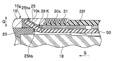
次に、挿入部3の先端側の内部の構成について、図2〜図4を用いて説明する。図2は、図1の内視鏡の挿入部の先端側を拡大して示す斜視図、図3は、図2中のIII-III線に沿う挿入部の先端側の断面図、図4は、図3中のIV-IV線に沿う先端部の断面図である。
In the apparatus main body 6, an image processing CPU, an electrical component such as a recording device that records a processed image, a battery unit that supplies power, and the like are provided. The battery power is supplied to the
Next, the internal configuration on the distal end side of the insertion portion 3 will be described with reference to FIGS. 2 is an enlarged perspective view showing the distal end side of the insertion portion of the endoscope of FIG. 1, FIG. 3 is a sectional view of the distal end side of the insertion portion along the line III-III in FIG. 2, and FIG. FIG. 4 is a cross-sectional view of the tip portion taken along line IV-IV in FIG. 3.
図2〜図4に示すように、先端部3aは、該先端部3aを構成する複数の内蔵物を覆う、例えば金属や樹脂等から構成されたカバー部材10を具備している。カバー部材10の内部には、複数の内蔵物が接着剤20等によって固定されて設けられている。
As shown in FIGS. 2-4, the front-end | tip
具体的には、図3に示すように、カバー部材10の内部において、先端側には、レンズ枠13によって保持された複数のレンズ12が、最も先端側に位置するレンズが先端部3aの先端面から露出するよう設けられている。
Specifically, as shown in FIG. 3, a plurality of
また、レンズ枠13の基端側の外周には、素子枠14の先端側の外周が固定されており、素子枠14の基端側の内部には、プリズム15が固定されており、さらに、プリズム15の出射面には、撮像素子16が固定されている。よって、複数のレンズ12に入光された被検体内の像は、プリズム15を介して撮像素子16に入光されて撮像される。
Further, the outer periphery on the distal end side of the
撮像素子16に、電気基板17が電気的に接続されており、該電気基板17に、装置本体6からユニバーサルコード5、操作部4、挿入部3内に挿入された信号ケーブル21の先端が電気的に接続されている。尚、信号ケーブル21の先端と電気基板17との固定部位は、樹脂等の充填剤19によって覆われている。
An
このことにより、撮像素子16によって撮像された被検部位の像は、信号ケーブル21を介して装置本体6へと伝送され、装置本体6内のCPUによって画像処理された後、モニタ6aに、内視鏡画像として表示される。
As a result, the image of the region to be examined imaged by the
また、カバー部材10の内部には、操作部4内に設けられた発光素子から発光された光を、先端部3aの先端面まで伝送する、挿入部3内に挿通されたライトガイド18の先端側も挿通されている。
Further, inside the
湾曲部3bは、図3に示すように、複数の湾曲駒が挿入方向Sに沿って連結された湾曲管32と、該湾曲管32の外周を被覆する、例えばゴムから構成された軟性チューブ部材30とを具備して主要部が構成されている。
As shown in FIG. 3, the bending
湾曲管32は、先端側の部位、即ち、複数の湾曲駒の内、最も先端側に位置する湾曲駒32fが、カバー部材10の基端10k内に、接着剤等を介して嵌合固定されている。尚、以下、カバー部材10の基端10k内に対して湾曲駒32fが嵌合された位置を嵌合部位Kと称す。
The bending
また、軟性チューブ部材30の先端30sは、カバー部材10の基端10kに非接着で突き当てられた状態において、湾曲駒32fの外周に糸巻き接着31によって固定されている。
Further, the
よって、本実施の形態の構成においては、図2、図3に示すように、軟性チューブ部材30の先端30sは、従来の構成のようにカバー部材10の基端10kの外周を被覆していないことから、カバー部材10と軟性チューブ部材30とは略同径となっており、カバー部材10と軟性チューブ部材30との挿入方向Sにおける間に段差等が発生しない構成となっている。
Therefore, in the configuration of the present embodiment, as shown in FIGS. 2 and 3, the
また、図3に示すように、湾曲部3b内には、湾曲部3bを上下方向に湾曲させる、挿入部3内に挿通されたループ形状を有する牽引ワイヤ50の先端側が挿通されている。尚、ループ形状を有する牽引ワイヤ50の基端側は、操作部4内に設けられた図示しないプーリ等に巻回されている。
Further, as shown in FIG. 3, the distal end side of a pulling
次に、牽引ワイヤ50の先端側の固定構造について説明する。図2〜図4に示すように、カバー部材10の外周面10gにおいて、基端10kの近傍部位に、カバー部材10の周方向Cに沿って、所定の長さ、例えば半周以上の長さを有する有底の溝11が形成されている。
Next, a fixing structure on the distal end side of the pulling
また、図3、図4に示すように、溝11の周方向Cにおける少なくとも2箇所、例えば一端11i及び他端11tの底部に、カバー部材10の内部に連通する孔25、26がそれぞれ形成されている。尚、孔25、26は、一端11i及び他端11tに限らず、溝11内であれば、どの位置に形成されていても構わない。
As shown in FIGS. 3 and 4, holes 25 and 26 communicating with the inside of the
溝11は、図2、図4に示すように、孔25、26を介して、カバー部材10の内部からループ形状を有する牽引ワイヤ50の先端側が巻き付けられるものである。具体的には、溝11には、孔25を介してカバー部材10内から溝11に進入するととともに、孔26を介して溝11からカバー部材10内に進入するよう、牽引ワイヤ50が巻き付けられている。
As shown in FIGS. 2 and 4, the
尚、牽引ワイヤ50は、溝11の底部に巻き付けられた状態において、溝11からカバー部材10の径方向Qの外側に、牽引ワイヤ50の一部が飛び出すことがないよう、溝11の深さ以下の外径に形成されている。言い換えれば、溝11の深さは、牽引ワイヤ50の外径以上に形成されている。
It should be noted that when the pulling
これは、溝11に牽引ワイヤ50が巻き付けられた状態において、牽引ワイヤ50の一部が溝11から、即ち、カバー部材10の外周面10gから径方向Qの外側にはみ出てしまうと、先端部3aの径がはみ出た牽引ワイヤ50の分だけ大きくなってしまうためである。
This is because, when the pulling
また、牽引ワイヤ50は、溝11に巻き付けられた状態において、水密を確保する目的や、牽引ワイヤ50の溝11からのはみ出しを防止する目的から固定部材である接着剤20によって固定されている。尚、図2においては、図面を簡略化するため、接着剤20を省略して示している。
In addition, the pulling
また、固定部材としては、接着剤20に限らず、溶接、ロウ付け、半田等であっても構わない。また、接着剤20は、溝11に限らず、孔25、26内にも注入されている。このことにより、溝11に巻き付けられた牽引ワイヤ50の位置が移動してしまうことがない他、水密性が確保されている。
なお、前述した有底の溝11は、カバー部材10の周方向Cに沿って、半周以上の長さを有する例で示したが、これに限られるものではなく、牽引ワイヤ50の先端側が溝11に巻きつけられた状態において、カバー部材10の外周面10gから径方向Qの外側にはみ出していなければ良いので、例えばカバー部材10の外周面の全周に溝を設けるようにしてもよい。この場合、牽引ワイヤ50を巻きつけた後、カバー部材10の全周に設けた溝に対して、水密確保及び牽引ワイヤ50のはみ出し防止のために接着剤等の固定部材で固定することが好ましい。
Further, the fixing member is not limited to the adhesive 20 and may be welding, brazing, solder, or the like. Further, the adhesive 20 is injected not only into the
In addition, although the bottomed groove |
以上から、牽引ワイヤ50の先端側は、カバー部材10の外周面10gに形成された溝11に巻き付けられて固定されている。よって、図3中、上側の牽引ワイヤ50が牽引されると、湾曲部3bは上方向に湾曲され、図3中、下側の牽引ワイヤ50が牽引されると、湾曲部3bは下方向に湾曲される。
From the above, the leading end side of the pulling
ここで、孔25、26は、上述したカバー部材10の基端10k内への湾曲駒32fの嵌合部位Kよりも挿入方向Sの前方に位置している。
Here, the
これは、仮に、孔25、26が嵌合部位Kよりも後方に位置していると、即ち、軟性チューブ部材30に形成されていると、牽引ワイヤ50の先端側を、湾曲管32か軟性チューブ部材30に固定しなければならなくなるが、上述したように、湾曲管32に固定すると湾曲管の内部空間が狭くなってしまうという問題があり、また、軟性チューブ部材30の外周面に牽引ワイヤ50の先端側を巻き付けて固定することは、固定強度を確保する上で困難であるためである。
If the
また、孔25、26は、図3に示すように、溝11側の開口25ha、26haが、カバー部材10内の開口25hb、26hbよりも挿入方向Sの前方に位置するよう、傾いてカバー部材10に形成されている。
Further, as shown in FIG. 3, the
これは、仮に孔25、26が挿入方向Sに垂直な孔に形成されていると、開口25hb、26hbを介して、孔25、26内に進入する牽引ワイヤ50を90°屈曲させなければならず、牽引ワイヤ50へのダメージが大きくなってしまうが、孔25、26が挿入方向Sの前方に傾いておれば、開口25hb、26hbを介して、孔25、26内に進入する牽引ワイヤ50の屈曲角度を鈍角にすることができることから、牽引ワイヤ50への屈曲の際のダメージを小さくすることができるためである。
This is because if the
ここで、図3に示すように、牽引ワイヤ50は、湾曲部3b内においては、複数の湾曲駒に形成されたワイヤ受け部材33によって周方向Cに180°ずれた状態でそれぞれ支持されているが、各孔25、26の開口25hb、26hbは、ワイヤ受け部材33と挿入方向Sにおいて同軸上に位置している。即ち、開口25hb、26hbとワイヤ受け部材33の周方向Cの位置は一致している。これは、ワイヤ受け部材33によって支持された牽引ワイヤ50が開口25hb、26hbを介して孔25、26に嵌入する際、捻れてしまうのを防止するためである。
Here, as shown in FIG. 3, the pulling
このように、本実施の形態においては、湾曲管32は、湾曲駒32fが、カバー部材10の基端10k内に、接着剤等を介して嵌合固定されており、軟性チューブ部材30の先端30sは、カバー部材10の基端10kに突き当てられた状態で、湾曲駒32fの外周に糸巻き接着31によって固定されていると示した。
As described above, in the present embodiment, the bending
また、牽引ワイヤ50の先端側は、カバー部材10の外周面10gに形成された溝11に、孔25、26を介して巻き付けられており、接着剤20で固定されることにより水密性が確保されていると示した。
Further, the leading end side of the pulling
このことによれば、従来の構成のように、水密性を確保するため、軟性チューブ部材30の先端30sをカバー部材10の基端10kの外周に被覆する必要がないことから、カバー部材10と軟性チューブ部材30とは略同径となっており、カバー部材10と軟性チューブ部材30との挿入方向Sにおける間に段差等が発生しない。このため、挿入部3の先端側の外径を小さくすることができることから、被検体内への挿入部3の挿入性が向上される。
According to this, since it is not necessary to cover the outer periphery of the
さらには、軟性チューブ部材30の先端30sをカバー部材10の基端10kの外周に被覆する必要がないことから、従来の構成のように、溝11を避けたカバー部材10の外周面10gの位置に、軟性チューブ部材30の先端を固定する必要がないため、先端部3aの長さを短くすることができることから、被検体内への挿入部3の挿入性が向上される。
Further, since it is not necessary to cover the outer periphery of the
また、牽引ワイヤ50の先端側は、従来のように湾曲管32に固定されておらず、カバー部材10の外周面10gに形成された溝11に固定されていることから、カバー部材10の基端10k及び湾曲部3bの内部空間を狭くしてしまうことがない。
Further, the distal end side of the pulling
さらに、溝11に対して接着剤20のみで牽引ワイヤ50の先端側を固定することができることから、従来のように、カバー部材10において、牽引ワイヤ50を固定するビスが固定される肉厚を確保する必要がないため、カバー部材10の基端側における内部空間が狭くなってしまうことがない他、カバー部材10の脱落を、溝11への牽引ワイヤ50の固定によって容易に防止することができる。
Furthermore, since the tip end side of the pulling
また、従来のように、カバー部材10と軟性チューブ部材30とを同径にするため、軟性チューブ部材の先端側が被覆されるカバー部材の基端を、径方向Qの内側に入り込んで位置させる必要も無いことから、カバー部材10の基端側における内部空間が狭くなってしまうことがない。
Further, as in the prior art, in order to make the
よって、カバー部材10の基端10k内及び湾曲部3b内の内部空間を広く確保することができることから、ライトガイド18の本数を増やすことができるため、光量を多くすることができる他、信号ケーブル21を太くすることができるため、画像ノイズを低減させることができる。
Therefore, since the internal space in the
以上から、挿入部3の先端側の細径化を図りながら内部空間を十分に確保しつつ、先端部3aを短くすることができる構成を有する内視鏡2を提供することができる。
From the above, it is possible to provide the
尚、以下、変形例を、図5〜図7を用いて示す。図5は、図2の内視鏡の挿入部の先端側の変形例の構成を拡大して示す斜視図、図6は、図5中のVI-VI線に沿う挿入部の先端側の断面図、図7は、図6中のVII-VII線に沿う先端部の断面図である。 Hereinafter, modified examples will be described with reference to FIGS. 5 is an enlarged perspective view showing a configuration of a modification of the distal end side of the insertion portion of the endoscope of FIG. 2, and FIG. 6 is a sectional view of the distal end side of the insertion portion along line VI-VI in FIG. FIGS. 7A and 7B are cross-sectional views of the tip portion taken along line VII-VII in FIG.
上述した本実施の形態においては、湾曲部3bは、上下方向の2方向に湾曲自在であり、挿入部3内には、湾曲部3bを上下方向に湾曲させる、ループ形状を有する1本の牽引ワイヤ50が挿通されていると示した。
In the present embodiment described above, the bending
これに限らず、湾曲部3bは、2方向以上に湾曲自在であっても構わない。以下、図5〜図7を用いて湾曲部3bが、例えば上下左右の4方向に湾曲自在な場合の構成について、説明する。尚、図5、図7においては、図面を簡略化するため、接着剤20を省略して示している。
Not limited to this, the bending
図6、図7に示すように、挿入部3内には、ループ形状を有する上下湾曲用の牽引ワイヤ50の他、ループ形状を有する左右湾曲用の牽引ワイヤ55が、例えば牽引ワイヤ50に対して周方向Cに90°ずれた位置に挿通されている。
As shown in FIGS. 6 and 7, in the insertion portion 3, in addition to the pulling
尚、牽引ワイヤ55の基端側も、牽引ワイヤ50の基端側と同様に、操作部4内に設けられた牽引ワイヤ50が巻回されたプーリとは別のプーリに巻回されている。
Note that the base end side of the pulling
また、図5、図6に示すように、カバー部材10の外周面10gにおいて、溝11よりも前方に、周方向Cに沿って所定の長さ、例えば半周以上の長さを有する有底の溝23が形成されている。尚、溝23は、溝11に対して、周方向Cに90°ずれて位置している。
As shown in FIGS. 5 and 6, the outer
また、溝23においても、例えば溝11の周方向Cにおける一端11i及び他端11tから90°ずれた位置における周方向Cの一端及び他端の底部に、カバー部材10の内部に連通する図示しない孔がそれぞれ形成されている。
Also in the
溝23は、図5、図6に示すように、溝23の一端及び他端の孔を介して、カバー部材10の内部からループ形状を有する牽引ワイヤ55の先端側が巻き付けられるものである。具体的には、溝23には、一端の孔を介してカバー部材10内から溝23に進入するととともに、他端の孔を介して溝23からカバー部材10内に進入するよう、牽引ワイヤ55が巻き付けられている。
As shown in FIGS. 5 and 6, the
尚、牽引ワイヤ55は、牽引ワイヤ50と同様に、溝23の底部に巻き付けられた状態において、溝23からカバー部材10の径方向Qの外側に、牽引ワイヤ55の一部が飛び出すことがないよう、溝23の深さ以下の外径に形成されている。
Similar to the
また、牽引ワイヤ55は、牽引ワイヤ50と同様に、溝23に巻き付けられた状態において、水密を確保する目的と溝23からの牽引ワイヤ55のはみ出しを防止する目的から図示しない上述した固定部材によって固定されている。尚、固定部材は、当然、溝23に形成された孔にも嵌入されている。
In addition, the pulling
このことにより、溝23に巻き付けられた牽引ワイヤ55の位置が移動してしまうことがない他、水密性が確保されている。以上から、牽引ワイヤ55の先端側は、カバー部材10の外周面10gに形成された溝11とは異なる溝23に巻き付けられて固定されている。よって、図7中、左側の牽引ワイヤ55が牽引されると、湾曲部3bは左方向に湾曲され、図7中、右側の牽引ワイヤ55が牽引されると、湾曲部3bは右方向に湾曲される。
As a result, the position of the pulling
尚、溝23に形成された孔の形状は、溝11に形成された孔25、26と同じであるため、その説明は省略する。
In addition, since the shape of the hole formed in the
以上、説明したように、カバー部材10の外周面10gには、牽引ワイヤに応じた数の溝が、それぞれ挿入方向Sにずれた位置において形成されていてもよい。よって、挿入部3内にループ形状を有する牽引ワイヤが3本以上挿通されている場合には、カバー部材10の外周面10gには、牽引ワイヤの数に応じた溝が、挿入方向Sにずれて形成されていれば良い。
As described above, the outer
このような構成によれば、2方向以上に湾曲する湾曲部3bを内視鏡2が有していたとしても、本実施の形態と同様の効果を得ることができる。
According to such a configuration, even if the
(第2実施の形態)
図8は、本実施の形態の内視鏡の挿入部における先端部と湾曲部との嵌合部位を拡大して示す部分断面図、図9は、図8の湾曲管の先端側を拡大して示す平面図、図10は、図8から牽引ワイヤと接着剤とを省略して示した嵌合部位の部分断面図である。
(Second Embodiment)
FIG. 8 is an enlarged partial cross-sectional view showing a fitting portion between the distal end portion and the bending portion in the insertion portion of the endoscope of the present embodiment, and FIG. 9 is an enlarged view of the distal end side of the bending tube in FIG. FIG. 10 is a partial cross-sectional view of a fitting portion in which the pulling wire and the adhesive are omitted from FIG.
この第2実施の形態の内視鏡の構成は、上述した図1〜図7に示した第1実施の形態の内視鏡と比して、カバー部材の溝の一端及び他端に形成された孔におけるカバー部材内の開口が、カバー部材の基端内への湾曲管の先端側の嵌合部位に位置している点が異なる。よって、この相違点のみを説明し、第1実施の形態と同様の構成には同じ符号を付し、その説明は省略する。 The configuration of the endoscope according to the second embodiment is formed at one end and the other end of the groove of the cover member as compared with the endoscope according to the first embodiment shown in FIGS. The difference is that the opening in the cover member in the hole is located at the fitting portion on the distal end side of the bending tube into the proximal end of the cover member. Therefore, only this difference will be described, the same reference numerals are given to the same components as those in the first embodiment, and the description thereof will be omitted.
図8、図10に示すように、本実施の形態におけるカバー部材10の外周面10gに形成された溝11の周方向Cの一端11i及び他端11tの孔25、26は、カバー部材10内の開口25hb、26hb(開口26hbは図示されず)が、カバー部材10の基端10k内への湾曲駒32fの嵌合部位Kに位置している。
As shown in FIGS. 8 and 10, the
即ち、本実施の形態の孔25、26は、上述した第1実施の形態の孔25、26よりもカバー部材10の外周面10gに対して大きく傾いている。
That is, the
また、図9、図10に示すように、嵌合部位Kに位置する湾曲駒32fの先端側に、孔25、26に連通するとともに、図8に示すように牽引ワイヤ50が挿通される挿入方向Sに沿ったスリット39が形成されている。
Further, as shown in FIGS. 9 and 10, insertion is performed in which the pulling
尚、その他の構成は、上述した第1実施の形態と同じである。 Other configurations are the same as those in the first embodiment described above.
このような構成によれば、スリット39に牽引ワイヤ50が挿通されているため、湾曲駒32fが周方向Cに回転してしまうことが無いことから、組み立て時において、容易に牽引ワイヤ50と湾曲管32との周方向Cの位置決めを行うことができ、組み立て精度を向上させることができる。
According to such a configuration, since the pulling
また、孔25、26が第1実施の形態よりもカバー部材10の外周面10gに対して大きく傾いていることから、開口25hb、26hbを介して、孔25、26内に進入する牽引ワイヤ50の屈曲角度を、第1実施の形態よりも鈍角にすることができ、牽引ワイヤ50への屈曲の際のダメージを第1実施の形態よりも小さくすることができる。
Moreover, since the
さらに、スリット39は、孔25、26に連通することから、即ち、スリット39の挿入方向Sの長さ分だけ、湾曲駒32fを前方に嵌合させることができることから、スリット39の長さ分だけ、カバー部材10の後端10kを短くすることができるため先端部3aの挿入方向Sの長さを短く形成することができる。尚、その他の効果は、上述した第1実施の形態と同様である。
Further, since the
尚、以下、変形例を、図11〜図14を用いて示す。図11は、湾曲管に牽引ワイヤを巻き付ける変形例の構成における挿入部の先端側を拡大して示す斜視図、図12は、図11の先端部を図12中のXII方向からみた側面図、図13は、図12中のXIII-XIII線に沿う挿入部の先端側の断面図、図14は、図12中のXIV-XIV線に沿う挿入部の先端側の断面図である。 Hereinafter, modified examples will be described with reference to FIGS. 11 is an enlarged perspective view showing the distal end side of the insertion portion in the configuration of the modified example in which the pulling wire is wound around the bending tube, and FIG. 12 is a side view of the distal end portion of FIG. 11 viewed from the XII direction in FIG. 13 is a cross-sectional view of the distal end side of the insertion portion taken along line XIII-XIII in FIG. 12, and FIG. 14 is a sectional view of the distal end side of the insertion portion taken along line XIV-XIV in FIG.
上述した第1、第2実施の形態においては、湾曲部3bを湾曲させる牽引ワイヤ50、は、カバー部材10の外周面10gの溝に巻き付けられて固定されていると示した。
In the first and second embodiments described above, the pulling
これに限らず、図11〜図14に示すように、湾曲駒32fの外周面32fgに牽引ワイヤ50を巻き付け、外周面32fgを覆うカバー部材10の基端10kに、牽引ワイヤ50が嵌入するスリット60が設けられた構成を有していても構わない。
Not only this, but as shown in FIGS. 11-14, the
このような構成によれば、湾曲駒32fの外周面32fgに牽引ワイヤ50が巻き付けられているため、内部空間が狭くなることがない他、湾曲駒32fの外周面32fgに牽引ワイヤ50が巻き付けられていたとしても、牽引ワイヤ50はカバー部材10の基端10kのスリット60に嵌入していることから、牽引ワイヤ50によってカバー部材10が径方向Qの外側に広げられてしまうことがない。即ち、カバー部材10が径方向Qに大きくなってしまうことがない。
According to such a configuration, since the pulling
よって、図11に示すように、本構成においては、湾曲駒32fの外周面32fgに巻き付けられている牽引ワイヤ50がカバー部材10の外周面10gに露出することがない。
Therefore, as shown in FIG. 11, in this configuration, the pulling
さらに、カバー部材10は、スリット60が牽引ワイヤ50に引っ掛かっているため、カバー部材10の脱落を容易に防止することができる。
Furthermore, the
また、以下、別の変形例を、図15を用いて示す。図15は、図4のカバー部材の溝に対して、牽引ワイヤが溝の複数の孔に対して並縫い状に嵌入されている変形例を示す断面図である。 Hereinafter, another modification will be described with reference to FIG. FIG. 15 is a cross-sectional view showing a modification in which the pulling wire is inserted into the plurality of holes of the groove in a side-by-side stitch shape with respect to the groove of the cover member in FIG. 4.
上述した第1、第2実施の形態においては、溝11には、孔25を介してカバー部材10内から溝11に進入するととともに、孔26を介して溝11からカバー部材10内に進入するよう、牽引ワイヤ50が巻き付けられていると示した。
In the first and second embodiments described above, the
これに限らず、図15に示すように、溝11における一端11iから他端11tまでの間の周方向Cの領域に、カバー部材10の内部に連通する孔を、孔25,26以外に、複数の孔71、72として設け、孔25、71、72、26に対して牽引ワイヤ50を並縫い状に嵌入させた状態で、溝11に牽引ワイヤ50が巻き付けられた構成であっても構わない。
Not limited to this, as shown in FIG. 15, in the region in the circumferential direction C between the one
このような構成によれば、溝11に対して牽引ワイヤ50を上述した第1、第2実施の形態よりもより強固に固定することができる。尚、孔25、26との間に形成される孔の数は、2つに限定されないことは勿論である。
According to such a configuration, the pulling
2…内視鏡
3…挿入部
3a…先端部
3b…湾曲部
10…カバー部材
10g…カバー部材の外周面
10k…カバー部材の基端
11…溝
11i…溝の一端
11t…溝の他端
20…接着剤(固定部材)
23…溝
25…孔(一方の孔)
25ha…溝側の開口
25hb…カバー部材内の開口
26…孔(他方の孔)
26ha…溝側の開口
26hb…カバー部材内の開口
30…軟性チューブ部材
30s…軟性チューブ部材の先端
32…湾曲管
32f…湾曲駒(湾曲管の先端側)
33…ワイヤ受け部材
39…スリット
50…牽引ワイヤ
71…孔
72…孔
C…周方向
K…嵌合部位
S…挿入方向
DESCRIPTION OF
23 ... groove 25 ... hole (one hole)
25ha ... opening on the groove side 25hb ... opening in the
26ha ... opening on groove side 26hb ... opening in
33 ...
Claims (9)
前記カバー部材の外周面において、前記カバー部材の周方向に沿って形成された溝と、
前記溝の前記周方向における少なくとも2箇所に位置する、前記カバー部材の内部に連通する前記カバー部材に形成された孔と、
前記挿入部において、前記先端部よりも前記挿入方向の後方に位置する、湾曲管及び該湾曲管を被覆する軟性チューブ部材を有し、前記湾曲管の前記挿入方向の先端側が、前記カバー部材の挿入方向の基端内に嵌合され、前記軟性チューブ部材の前記挿入方向の先端が、前記カバー部材の前記基端に突き当てられた湾曲部と、
前記湾曲部を複数方向に湾曲させる、前記挿入部内に挿通され前記溝の深さ以下の外径に形成されるとともにループ形状を有する、前記カバー部材において、一方の前記孔を介して前記カバー部材内から前記溝に進入するとともに、他方の前記孔を介して前記溝から前記カバー部材内に進入するよう前記溝に巻き付けられた牽引ワイヤと、
を具備していることを特徴とする内視鏡。
A cover member that covers a built-in object of the distal end, constituting a distal end on the distal end side in the insertion direction of the insertion portion to be inserted into the subject;
On the outer peripheral surface of the cover member, a groove formed along the circumferential direction of the cover member;
A hole formed in the cover member that communicates with the inside of the cover member, located at at least two locations in the circumferential direction of the groove;
The insertion portion includes a bending tube and a flexible tube member covering the bending tube, which is located behind the distal end portion in the insertion direction, and a distal end side of the bending tube in the insertion direction is the cover member. A bending portion that is fitted into the proximal end in the insertion direction, and the distal end in the insertion direction of the flexible tube member is abutted against the proximal end of the cover member;
In the cover member, the cover member is bent through one of the holes in the cover member, wherein the cover member is curved in a plurality of directions, is inserted into the insertion portion and has an outer diameter equal to or less than the depth of the groove. A pulling wire wound around the groove so as to enter the groove from the inside and enter the cover member from the groove through the other hole;
An endoscope characterized by comprising:
2. The inner portion according to claim 1, wherein the pulling wire is fixed to the groove by a fixing member so as not to protrude from the outer peripheral surface of the cover member to the outer side in the radial direction of the cover member. Endoscope.
Each of the one and the other holes formed in the groove is positioned in front of the fitting direction on the distal end side of the bending tube into the base end of the cover member in the insertion direction. The endoscope according to claim 1, wherein the endoscope is provided.
Each of the one and the other holes is formed in the cover member so as to be inclined so that the opening on the groove side is located in front of the opening in the cover member in the insertion direction. The endoscope according to any one of claims 1 to 3.
前記一方及び前記他方の前記各孔における前記カバー部材内の開口は、前記ワイヤ受け部材と前記挿入方向において同軸上に設けられていることを特徴とする請求項1〜4のいずれか1項に記載の内視鏡。
The pulling wire is supported in the bending tube by a wire receiving member provided on the bending tube,
The opening in the cover member in each of the one and the other holes is provided coaxially with the wire receiving member in the insertion direction. The endoscope described.
前記カバー部材の外周面には、前記牽引ワイヤに応じた数の前記溝が形成されていることを特徴とする請求項1〜5のいずれか1項に記載の内視鏡。
A plurality of the pulling wires are inserted into the insertion portion,
The endoscope according to any one of claims 1 to 5, wherein a number of the grooves corresponding to the pulling wire is formed on an outer peripheral surface of the cover member.
前記牽引ワイヤは、前記複数の孔を前記一方の孔から前記他方の孔まで並縫い状に嵌入して、前記溝に巻き付けられていることを特徴とする請求項1〜6のいずれか1項に記載の内視鏡。
In the groove, a plurality of the holes are further formed between the one hole and the other hole in the circumferential direction,
7. The pulling wire is wound around the groove by inserting the plurality of holes in a side-by-side manner from the one hole to the other hole. The endoscope according to 1.
前記嵌合部位に位置する前記湾曲管の前記先端側に、各前記孔に連通するとともに、前記牽引ワイヤが挿通されるスリットが形成されていることを特徴とする請求項1〜7のいずれか1項に記載の内視鏡。
The opening in the cover member in each of the one and the other holes is located at a fitting portion on the distal end side of the bending tube into the base end of the cover member,
8. The slit according to claim 1, wherein a slit is formed on the distal end side of the bending tube located at the fitting site, the slit being connected to each hole and through which the pulling wire is inserted. The endoscope according to item 1.
前記軟性チューブ部材の先端側と前記カバー部材の基端側とが突き当てられている面よThe surface on which the distal end side of the flexible tube member and the proximal end side of the cover member are abutted りも前記挿入方向の前方に位置していることを特徴とする請求項1〜8のいずれか1項The arbor is located in front of the insertion direction. に記載の内視鏡。The endoscope according to 1.
Priority Applications (4)
| Application Number | Priority Date | Filing Date | Title |
|---|---|---|---|
| JP2011175315A JP5734786B2 (en) | 2011-08-10 | 2011-08-10 | Endoscope |
| US13/567,387 US20130041223A1 (en) | 2011-08-10 | 2012-08-06 | Endoscope |
| EP12005787A EP2556789A1 (en) | 2011-08-10 | 2012-08-09 | Endoscope |
| CN201210282746.7A CN102928974B (en) | 2011-08-10 | 2012-08-09 | Endoscope |
Applications Claiming Priority (1)
| Application Number | Priority Date | Filing Date | Title |
|---|---|---|---|
| JP2011175315A JP5734786B2 (en) | 2011-08-10 | 2011-08-10 | Endoscope |
Publications (3)
| Publication Number | Publication Date |
|---|---|
| JP2013034787A JP2013034787A (en) | 2013-02-21 |
| JP2013034787A5 JP2013034787A5 (en) | 2014-09-11 |
| JP5734786B2 true JP5734786B2 (en) | 2015-06-17 |
Family
ID=46980668
Family Applications (1)
| Application Number | Title | Priority Date | Filing Date |
|---|---|---|---|
| JP2011175315A Active JP5734786B2 (en) | 2011-08-10 | 2011-08-10 | Endoscope |
Country Status (4)
| Country | Link |
|---|---|
| US (1) | US20130041223A1 (en) |
| EP (1) | EP2556789A1 (en) |
| JP (1) | JP5734786B2 (en) |
| CN (1) | CN102928974B (en) |
Families Citing this family (12)
| Publication number | Priority date | Publication date | Assignee | Title |
|---|---|---|---|---|
| WO2015125334A1 (en) * | 2014-02-18 | 2015-08-27 | オリンパス株式会社 | Endoscope curved tube |
| USD752744S1 (en) * | 2014-03-14 | 2016-03-29 | Zhejiang Youyi Medical Apparatus Co., Ltd. | Video laryngoscope |
| JP6293391B1 (en) * | 2016-05-19 | 2018-03-14 | オリンパス株式会社 | Imaging unit and endoscope |
| JP6349041B1 (en) | 2016-08-10 | 2018-06-27 | オリンパス株式会社 | Curved tube and endoscope |
| EP3628208A1 (en) * | 2018-09-28 | 2020-04-01 | Ambu A/S | An articulated tip part for an endoscope |
| EP3628205A1 (en) * | 2018-09-28 | 2020-04-01 | Ambu A/S | A method for manufacture of a tip part and a tip part for an endoscope |
| EP3628206B1 (en) | 2018-09-28 | 2023-05-03 | Ambu A/S | A method for manufacture of a tip part and a tip part for an endoscope |
| EP3636133B1 (en) * | 2018-10-12 | 2024-04-03 | Ambu A/S | An articulated tip part for an endoscope |
| US11806904B2 (en) | 2019-09-06 | 2023-11-07 | Ambu A/S | Tip part assembly for an endoscope |
| DE102020111455A1 (en) * | 2020-04-27 | 2021-10-28 | Schölly Fiberoptic GmbH | Flexible endoscope based on an investment material |
| DE102020111458A1 (en) | 2020-04-27 | 2021-10-28 | Schölly Fiberoptic GmbH | Flexible endoscope with a skeletal structure |
| EP3988006B1 (en) | 2020-10-20 | 2023-08-09 | Ambu A/S | An endoscope |
Family Cites Families (8)
| Publication number | Priority date | Publication date | Assignee | Title |
|---|---|---|---|---|
| JPS62227313A (en) | 1986-03-27 | 1987-10-06 | 旭光学工業株式会社 | Mount structure of curving operation wire of endoscope |
| JPH0546405Y2 (en) * | 1989-02-28 | 1993-12-06 | ||
| JP3780056B2 (en) * | 1997-03-19 | 2006-05-31 | オリンパス株式会社 | Fixing method of bending operation wire for endoscope |
| JP2001037705A (en) * | 1999-07-30 | 2001-02-13 | Olympus Optical Co Ltd | Endoscope |
| JP4262467B2 (en) * | 2002-10-29 | 2009-05-13 | オリンパス株式会社 | Endoscope |
| US7811277B2 (en) * | 2004-09-30 | 2010-10-12 | Boston Scientific Scimed, Inc. | Steerable device and system |
| US20060252993A1 (en) * | 2005-03-23 | 2006-11-09 | Freed David I | Medical devices and systems |
| JP2010167180A (en) * | 2009-01-26 | 2010-08-05 | Fujifilm Corp | Endoscope |
-
2011
- 2011-08-10 JP JP2011175315A patent/JP5734786B2/en active Active
-
2012
- 2012-08-06 US US13/567,387 patent/US20130041223A1/en not_active Abandoned
- 2012-08-09 CN CN201210282746.7A patent/CN102928974B/en active Active
- 2012-08-09 EP EP12005787A patent/EP2556789A1/en not_active Withdrawn
Also Published As
| Publication number | Publication date |
|---|---|
| CN102928974B (en) | 2016-09-14 |
| CN102928974A (en) | 2013-02-13 |
| US20130041223A1 (en) | 2013-02-14 |
| JP2013034787A (en) | 2013-02-21 |
| EP2556789A1 (en) | 2013-02-13 |
Similar Documents
| Publication | Publication Date | Title |
|---|---|---|
| JP5734786B2 (en) | Endoscope | |
| JP5250653B2 (en) | Endoscopic imaging apparatus and endoscope | |
| JP5192559B2 (en) | Endoscope | |
| JP5698877B1 (en) | Electronic endoscope | |
| JP4928984B2 (en) | Tip of ultra-thin endoscope | |
| JP5558600B2 (en) | Endoscope board connector, endoscope and manufacturing method thereof | |
| JP2009039434A (en) | Endoscope | |
| WO2012056851A1 (en) | Endoscope | |
| JP2009011462A (en) | Endoscope | |
| JP5558399B2 (en) | Endoscopic imaging device | |
| WO2013114661A1 (en) | Endoscope | |
| JPWO2013039059A1 (en) | Endoscope insertion shape observation probe | |
| WO2014123019A1 (en) | Bending device | |
| JP4881924B2 (en) | Industrial endoscope | |
| JP2008253451A (en) | Distal end structure of endoscope | |
| JP2010005277A (en) | Endoscope and method of assembling the same | |
| JP2008206624A (en) | Tip part for ultrafine diameter electronic endoscope | |
| JP5185572B2 (en) | Endoscope | |
| JP2008212310A (en) | Tip part of ultrathin electronic endoscope | |
| JP2009153901A (en) | Endoscope | |
| JP4504076B2 (en) | Endoscope | |
| JP2524408B2 (en) | Endoscope | |
| JP3174134B2 (en) | Endoscope | |
| JP2001149306A (en) | Endoscope | |
| JP2006014906A (en) | Distal end part of electronic endoscope |
Legal Events
| Date | Code | Title | Description |
|---|---|---|---|
| A521 | Request for written amendment filed |
Free format text: JAPANESE INTERMEDIATE CODE: A523 Effective date: 20140730 |
|
| A621 | Written request for application examination |
Free format text: JAPANESE INTERMEDIATE CODE: A621 Effective date: 20140730 |
|
| A977 | Report on retrieval |
Free format text: JAPANESE INTERMEDIATE CODE: A971007 Effective date: 20150227 |
|
| TRDD | Decision of grant or rejection written | ||
| A01 | Written decision to grant a patent or to grant a registration (utility model) |
Free format text: JAPANESE INTERMEDIATE CODE: A01 Effective date: 20150331 |
|
| A61 | First payment of annual fees (during grant procedure) |
Free format text: JAPANESE INTERMEDIATE CODE: A61 Effective date: 20150415 |
|
| R151 | Written notification of patent or utility model registration |
Ref document number: 5734786 Country of ref document: JP Free format text: JAPANESE INTERMEDIATE CODE: R151 |
|
| S531 | Written request for registration of change of domicile |
Free format text: JAPANESE INTERMEDIATE CODE: R313531 |
|
| R350 | Written notification of registration of transfer |
Free format text: JAPANESE INTERMEDIATE CODE: R350 |
|
| R250 | Receipt of annual fees |
Free format text: JAPANESE INTERMEDIATE CODE: R250 |
|
| R250 | Receipt of annual fees |
Free format text: JAPANESE INTERMEDIATE CODE: R250 |
|
| R250 | Receipt of annual fees |
Free format text: JAPANESE INTERMEDIATE CODE: R250 |
|
| R250 | Receipt of annual fees |
Free format text: JAPANESE INTERMEDIATE CODE: R250 |
|
| S111 | Request for change of ownership or part of ownership |
Free format text: JAPANESE INTERMEDIATE CODE: R313111 |
|
| R371 | Transfer withdrawn |
Free format text: JAPANESE INTERMEDIATE CODE: R371 |
|
| S111 | Request for change of ownership or part of ownership |
Free format text: JAPANESE INTERMEDIATE CODE: R313111 |
|
| R371 | Transfer withdrawn |
Free format text: JAPANESE INTERMEDIATE CODE: R371 |
|
| S111 | Request for change of ownership or part of ownership |
Free format text: JAPANESE INTERMEDIATE CODE: R313111 |
|
| R350 | Written notification of registration of transfer |
Free format text: JAPANESE INTERMEDIATE CODE: R350 |
|
| R250 | Receipt of annual fees |
Free format text: JAPANESE INTERMEDIATE CODE: R250 |
|
| R250 | Receipt of annual fees |
Free format text: JAPANESE INTERMEDIATE CODE: R250 |