JP5733112B2 - Vehicle and vehicle control method - Google Patents
Vehicle and vehicle control method Download PDFInfo
- Publication number
- JP5733112B2 JP5733112B2 JP2011188340A JP2011188340A JP5733112B2 JP 5733112 B2 JP5733112 B2 JP 5733112B2 JP 2011188340 A JP2011188340 A JP 2011188340A JP 2011188340 A JP2011188340 A JP 2011188340A JP 5733112 B2 JP5733112 B2 JP 5733112B2
- Authority
- JP
- Japan
- Prior art keywords
- value
- battery
- evaluation
- discharge
- control device
- Prior art date
- Legal status (The legal status is an assumption and is not a legal conclusion. Google has not performed a legal analysis and makes no representation as to the accuracy of the status listed.)
- Active
Links
Images


Classifications
-
- Y—GENERAL TAGGING OF NEW TECHNOLOGICAL DEVELOPMENTS; GENERAL TAGGING OF CROSS-SECTIONAL TECHNOLOGIES SPANNING OVER SEVERAL SECTIONS OF THE IPC; TECHNICAL SUBJECTS COVERED BY FORMER USPC CROSS-REFERENCE ART COLLECTIONS [XRACs] AND DIGESTS
- Y02—TECHNOLOGIES OR APPLICATIONS FOR MITIGATION OR ADAPTATION AGAINST CLIMATE CHANGE
- Y02E—REDUCTION OF GREENHOUSE GAS [GHG] EMISSIONS, RELATED TO ENERGY GENERATION, TRANSMISSION OR DISTRIBUTION
- Y02E60/00—Enabling technologies; Technologies with a potential or indirect contribution to GHG emissions mitigation
- Y02E60/10—Energy storage using batteries
-
- Y—GENERAL TAGGING OF NEW TECHNOLOGICAL DEVELOPMENTS; GENERAL TAGGING OF CROSS-SECTIONAL TECHNOLOGIES SPANNING OVER SEVERAL SECTIONS OF THE IPC; TECHNICAL SUBJECTS COVERED BY FORMER USPC CROSS-REFERENCE ART COLLECTIONS [XRACs] AND DIGESTS
- Y02—TECHNOLOGIES OR APPLICATIONS FOR MITIGATION OR ADAPTATION AGAINST CLIMATE CHANGE
- Y02T—CLIMATE CHANGE MITIGATION TECHNOLOGIES RELATED TO TRANSPORTATION
- Y02T10/00—Road transport of goods or passengers
- Y02T10/60—Other road transportation technologies with climate change mitigation effect
- Y02T10/62—Hybrid vehicles
-
- Y—GENERAL TAGGING OF NEW TECHNOLOGICAL DEVELOPMENTS; GENERAL TAGGING OF CROSS-SECTIONAL TECHNOLOGIES SPANNING OVER SEVERAL SECTIONS OF THE IPC; TECHNICAL SUBJECTS COVERED BY FORMER USPC CROSS-REFERENCE ART COLLECTIONS [XRACs] AND DIGESTS
- Y02—TECHNOLOGIES OR APPLICATIONS FOR MITIGATION OR ADAPTATION AGAINST CLIMATE CHANGE
- Y02T—CLIMATE CHANGE MITIGATION TECHNOLOGIES RELATED TO TRANSPORTATION
- Y02T10/00—Road transport of goods or passengers
- Y02T10/60—Other road transportation technologies with climate change mitigation effect
- Y02T10/70—Energy storage systems for electromobility, e.g. batteries
-
- Y—GENERAL TAGGING OF NEW TECHNOLOGICAL DEVELOPMENTS; GENERAL TAGGING OF CROSS-SECTIONAL TECHNOLOGIES SPANNING OVER SEVERAL SECTIONS OF THE IPC; TECHNICAL SUBJECTS COVERED BY FORMER USPC CROSS-REFERENCE ART COLLECTIONS [XRACs] AND DIGESTS
- Y02—TECHNOLOGIES OR APPLICATIONS FOR MITIGATION OR ADAPTATION AGAINST CLIMATE CHANGE
- Y02T—CLIMATE CHANGE MITIGATION TECHNOLOGIES RELATED TO TRANSPORTATION
- Y02T10/00—Road transport of goods or passengers
- Y02T10/60—Other road transportation technologies with climate change mitigation effect
- Y02T10/72—Electric energy management in electromobility
Landscapes
- Hybrid Electric Vehicles (AREA)
- Secondary Cells (AREA)
- Electric Propulsion And Braking For Vehicles (AREA)
Description
本発明は、車両に搭載された電池の劣化を抑制する技術に関する。 The present invention relates to a technique for suppressing deterioration of a battery mounted on a vehicle.
大電流での電池の放電(以下、「ハイレート放電」ともいう)が継続されると、電池の内部抵抗が一時的(可逆的)に上昇する場合がある。このような状態が継続すると、電池の劣化を招く。 When the discharge of the battery with a large current (hereinafter also referred to as “high rate discharge”) is continued, the internal resistance of the battery may temporarily (reversibly) increase. If such a state continues, the battery will be deteriorated.
特許第4494453号公報(特許文献1)には、ハイレート放電の継続に起因する電池の劣化の度合いを示す劣化評価値を算出し、その劣化評価値が予め定められた目標値を超えた場合に電池の放電電力を制限することによって、ハイレート放電による電池の劣化を抑制する技術が開示されている。 In Japanese Patent No. 4494453 (Patent Document 1), a deterioration evaluation value indicating the degree of deterioration of a battery due to continuation of high-rate discharge is calculated, and the deterioration evaluation value exceeds a predetermined target value. A technique for suppressing deterioration of a battery due to high-rate discharge by limiting the discharge power of the battery is disclosed.
しかしながら、特許文献1に開示された技術は、劣化評価値が予め定められた目標値を超えたことに応じて電池の放電電力が制限されるため、予め定められた目標値が必要以上に小さい値に設定されると、電池の劣化が抑制され電池寿命を確保可能となるが、その一方で車両動力性能を十分には確保できなくなることも想定される。そのため、更なる改良の余地があった。
However, the technique disclosed in
本発明は、上述の課題を解決するためになされたものであって、その目的は、電池寿命の確保と車両動力性能の確保とを両立することである。 The present invention has been made to solve the above-described problems, and an object of the present invention is to ensure both battery life and vehicle power performance.
この発明に係る車両は、電池と、電池の放電を制御する制御装置とを備える。制御装置は、電池の放電継続に起因する電池の劣化の度合いを示す評価値の積算値が電池に要求される寿命を確保可能な許容値を超える場合、評価値の積算値が許容値未満である場合よりも電池の放電を制限することを促す処理を行なう。 The vehicle according to the present invention includes a battery and a control device that controls discharge of the battery. When the integrated value of the evaluation value indicating the degree of deterioration of the battery due to the continuous discharge of the battery exceeds the allowable value that can ensure the life required for the battery, the integrated value of the evaluation value is less than the allowable value. A process for urging to limit the discharge of the battery is performed more than in some cases.
好ましくは、制御装置は、制限条件の成立時に制限条件の不成立時よりも電池の放電を制限する。制御装置は、評価値の積算値が許容値を超える場合、評価値の積算値が許容値未満である場合よりも制限条件を成立し易い条件に変更する。 Preferably, the control device limits the discharge of the battery when the restriction condition is satisfied, compared to when the restriction condition is not satisfied. When the integrated value of the evaluation value exceeds the allowable value, the control device changes the condition so that the restriction condition is more easily established than when the integrated value of the evaluation value is less than the allowable value.
好ましくは、制限条件は、評価値がしきい値を超えたという条件である。制御装置は、評価値の積算値が許容値を超える場合、評価値の積算値が許容値未満である場合よりもしきい値を小さい値に変更する。 Preferably, the limiting condition is a condition that the evaluation value exceeds a threshold value. When the integrated value of the evaluation values exceeds the allowable value, the control device changes the threshold value to a smaller value than when the integrated value of the evaluation values is less than the allowable value.
好ましくは、制御装置は、評価値の積算値が許容値未満であるときはしきい値を基準値よりも大きい最大値とし、評価値の積算値が許容値を超えた場合はしきい値を最大値から基準値まで段階的に低下させる。 Preferably, the control device sets the threshold value to a maximum value larger than the reference value when the integrated value of the evaluation value is less than the allowable value, and sets the threshold value when the integrated value of the evaluation value exceeds the allowable value. Decrease in steps from the maximum value to the reference value.
好ましくは、制御装置は、直近の所定期間分の評価値の合計値を評価値の積算値として算出する。 Preferably, the control device calculates a total value of evaluation values for the latest predetermined period as an integrated value of the evaluation values.
好ましくは、制御装置は、電池を流れる電流の履歴から電池の電解質中におけるイオン濃度の偏りの変化を推定し、イオン濃度の偏りが増加すると推定される場合に評価値を増加させ、イオン濃度の偏りが減少すると推定される場合に評価値を低下させる。 Preferably, the control device estimates a change in the ion concentration bias in the battery electrolyte from the history of the current flowing through the battery, and increases the evaluation value when the ion concentration bias is estimated to increase. If the bias is estimated to decrease, the evaluation value is decreased.
この発明の別の局面に係る制御方法は、電池と電池の放電を制御する制御装置とを備えた車両の制御方法であって、電池の放電継続に起因する電池の劣化の度合いを示す評価値の積算値を算出するステップと、評価値の積算値が電池に要求される寿命を確保可能な許容値を超える場合、評価値の積算値が許容値未満である場合よりも電池の放電を制限することを促す処理を行なうステップとを含む。 A control method according to another aspect of the present invention is a vehicle control method including a battery and a control device for controlling discharge of the battery, and an evaluation value indicating a degree of deterioration of the battery due to continuous discharge of the battery The step of calculating the integrated value of the battery, and if the integrated value of the evaluation value exceeds the allowable value that can ensure the life required for the battery, the battery discharge is limited more than the case where the integrated value of the evaluation value is less than the allowable value. Performing a process for prompting the user to perform the process.
本発明によれば、電池寿命の確保と車両動力性能の確保とを両立することができる。 According to the present invention, both battery life and vehicle power performance can be ensured.
以下、図面を参照しつつ、本発明の実施の形態について説明する。以下の説明では、同一の部品には同一の符号を付してある。それらの名称および機能も同じである。したがって、それらについての詳細な説明は繰返さない。 Hereinafter, embodiments of the present invention will be described with reference to the drawings. In the following description, the same parts are denoted by the same reference numerals. Their names and functions are also the same. Therefore, detailed description thereof will not be repeated.
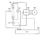
図1は、本実施の形態に係る車両の構造を示す図である。この車両は、エンジン100と、ジェネレータ200と、PCU(Power Control Unit)300と、バッテリ400と、モータ500と、これらに接続されたECU(Electronic Control Unit)600と、動力分配機構700と、減速機800と、車輪900とを含む。なお、図1に示す車両は、エンジン100、ジェネレータ200、モータ500を搭載したハイブリッド車両であるが、本発明を適用可能な車両は図1に示す車両に限定されず、電力エネルギを用いて走行する車両全般に適用可能である。
FIG. 1 is a diagram illustrating a structure of a vehicle according to the present embodiment. The vehicle includes an
エンジン100が発生する動力は、動力分配機構700により、車輪900およびジェネレータ200に分配される。
The power generated by the
ジェネレータ200は、動力分配機構700により分配されたエンジン100の動力により発電する。ジェネレータ200により発電された電力は、車両の運転状態やバッテリ400の残存容量(以下、「SOC(State Of Charge)」ともいう)に応じて使い分けられる。たとえば、通常走行時や急加速時では、ジェネレータ200により発電された電力はそのままモータ500を駆動させる電力となる。一方、バッテリ400のSOCが予め定められた値よりも低い場合、ジェネレータ200により発電された電力は、PCU300のインバータ302により交流電力から直流電力に変換され、コンバータ304により電圧が調整された後、バッテリ400に蓄えられる。
バッテリ400は、複数のリチウムイオン二次電池セルを一体化したモジュールを、さらに複数直列に接続して構成された組電池である。リチウムイオン二次電池セルの正極は、リチウムイオン(以下「Li塩」ともいう)を可逆的に吸蔵/放出可能な材料(たとえばリチウム含有酸化物)から成り、充電過程においてLi塩を電解液に放出し、放電過程において電解液中のLi塩を吸蔵する。リチウムイオン二次電池セルの負極は、Li塩を可逆的に吸蔵/放出可能な材料(たとえば炭素)から成り、充電過程において電解液中のLi塩を吸蔵し、放電過程においてLi塩を電解液に放出する。
The
モータ500は、三相交流モータであり、バッテリ400に蓄えられた電力およびジェネレータ200により発電された電力の少なくともいずれか一方の電力により駆動する。モータ500の駆動力は、減速機800を経由して車輪900に伝えられる。これにより、モータ500は、エンジン100をアシストして車両を走行させたり、モータ500からの駆動力のみにより車両を走行させたりする。
Motor 500 is a three-phase AC motor, and is driven by at least one of the electric power stored in
一方、車両の回生制動時には、減速機800を経由して車輪900によりモータ500が駆動され、モータ500がジェネレータとして作動させられる。これによりモータ500は、制動エネルギを電力に変換する回生ブレーキとして作用する。モータ500により発電された電力は、PCU300を経由してバッテリ400に蓄えられる。
On the other hand, during regenerative braking of the vehicle, the
ECU600は、図示しないCPU(Central Processing Unit)およびメモリを内蔵し、当該メモリに記憶されたマップおよびプログラムに基づいて、所定の演算処理を実行するように構成される。 ECU 600 includes a CPU (Central Processing Unit) and a memory (not shown), and is configured to execute predetermined arithmetic processing based on a map and a program stored in the memory.
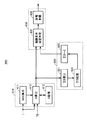
図2は、バッテリ400の周辺の構造を示す図である。図2に示すように、バッテリ400には、電圧センサ601と、電流センサ602と、温度センサ603とが設けられる。電圧センサ601は、バッテリ400の両端電圧(以下「バッテリ電圧VB」)を検出する。電流センサ602は、バッテリ400を流れる電流(以下「充放電電流I」ともいう)を検出する。なお、以下の説明においては、放電時には充放電電流Iが正の値となり、充電時には充放電電流Iが負の値となるものとして説明する。温度センサ603は、バッテリ400の温度(以下「バッテリ温度TB」ともいう)を検出する。これらの各センサは、検出結果をECU600に出力する。
FIG. 2 is a diagram illustrating a structure around the
ECU600は、バッテリ400の状態に応じて、充電電力上限値WINおよび放電電力上限値WOUT(単位はいずれもワット)を設定し、バッテリ400の実際の充電電力および放電電力がそれぞれ充電電力上限値WINおよび放電電力上限値WOUTを超えないように制御する。
以上のような構成を有する車両において、バッテリ400のハイレート放電が継続されると、バッテリ400の内部抵抗が一時的(可逆的)に上昇し、バッテリ400の出力電圧が低下する場合がある。ハイレート放電の継続による電解液中のLi塩の偏りが、その要因の1つと考えられている。
In the vehicle having the above configuration, when the high-rate discharge of the
このハイレート放電の継続によってバッテリ400の内部抵抗が一時的に上昇した状態が継続されると、バッテリ400の不可逆的な劣化を招いてしまう。これを防止するためには、ハイレート放電の継続を抑制する必要がある。その一方で、ハイレート放電の継続を抑制し過ぎると、ユーザが要求する車両動力性能を発揮することができなくなってしまうおそれがある。
If the state in which the internal resistance of the
そこで、本実施の形態によるECU600は、ハイレート放電の継続に起因するバッテリ400の劣化の度合いを示すバッテリ劣化評価値DをLi塩の偏りの変化に応じて算出する。そして、ECU600は、バッテリ劣化評価値Dが目標値Eを超えたという条件(以下、「制限条件」ともいう)が成立した場合に放電電力上限値WOUTを低下させてバッテリ400の放電を制限する(以下、この制限を「WOUT制限」ともいう)。このWOUT制限により、ハイレート放電によるバッテリ400の劣化を抑制する。
Therefore,
この際、ECU600は、バッテリ400に蓄積されたダメージ量に相当する値として、バッテリ劣化評価値Dを積算した値(以下「バッテリ劣化積算値ΣD」という)を算出する。そして、ECU600は、バッテリ劣化積算値ΣDが許容値を超えるまでは、制限条件の判定に用いられる目標値Eを最大値Emaxに設定することによって制限条件を成立し難くし(WOUT制限を介入され難くし)、バッテリ劣化積算値ΣDが許容値を超えた場合、目標値Eを最大値Emaxから基準値Ebaseに低下させることによって制限条件を成立し易くする(WOUT制限を介入され易くする)。この点が本発明の最も特徴的な点である。
At this time,
図3は、ECU600の機能ブロック図である。図3に示した各機能ブロックは、ハードウェアによって実現してもよいし、ソフトウェアによって実現してもよい。
FIG. 3 is a functional block diagram of
ECU600は、算出部610と、設定部620と、制御部630とを含む。
算出部610は、バッテリ400のLi塩の偏りの変化に応じて上述のバッテリ劣化評価値Dを算出する。算出部610は、算出部611と、記憶部612と、算出部613とを含む。算出部611は、充放電電流Iからバッテリ400のSOCを算出する。記憶部612は、算出部613で算出されたバッテリ劣化評価値Dを記憶する。算出部613は、放電電流値I、バッテリ温度TB、記憶部612に記憶されたバッテリ劣化評価値D(前回値)に基づいて、バッテリ劣化評価値D(今回値)を算出する。具体的な算出手法については後述の図5〜図7を用いて詳細に説明する。
The
制御部630は、バッテリ劣化評価値Dと目標値Eとの比較結果に応じて、バッテリ400の実際の放電電力(以下「実放電電力P」という)を制御する。制御部630は、判定部631、制限部632を含む。
判定部631は、上述の制限条件(バッテリ劣化評価値Dが目標値Eを超えたという条件)の成否を判定する。
The
制限部632は、制限条件が成立した場合、上述のWOUT制限を行なう。すなわち、制限部632は、制限条件が成立した場合、制限条件が不成立である場合よりも、放電電力上限値WOUTを小さい値に設定する。そして、制限部632は、実放電電力Pが放電電力上限値WOUTを越えないように、PCU300を制御する。これにより、制限条件の成立時は不成立時よりも実放電電力Pが制限されることになる。
The
設定部620は、制限条件の判定に用いられる目標値Eを、バッテリ劣化積算値ΣDに応じて可変制御する。設定部620は、積算部621、記憶部622、目標値設定部623を含む。
The
積算部621は、直近の所定期間分(たとえば14日分)のバッテリ劣化評価値Dの合計値を「バッテリ劣化積算値ΣD」として算出する。なお、バッテリ劣化積算値ΣDの算出手法はこれに限定されない。
積算部621は、バッテリ劣化評価値Dが所定値D0(<0)から所定値D1(>0)までに含まれる場合は、バッテリ劣化評価値Dとバッテリ400に蓄積されたダメージ量との相関が低いため、バッテリ劣化積算値ΣDの算出を行なわない。
When the battery deterioration evaluation value D is included from the predetermined value D0 (<0) to the predetermined value D1 (> 0), the
記憶部622は、積算部621が算出したバッテリ劣化積算値ΣDを記憶する。
目標値設定部623は、記憶部622に記憶されたバッテリ劣化積算値ΣDを読み出し、バッテリ劣化積算値ΣDに応じて目標値Eを可変制御する。
The
The target
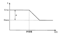
図4は、バッテリ劣化積算値ΣDと目標値Eとの対応関係を示す図である。図4に示すように、バッテリ劣化積算値ΣDが許容値未満の範囲では、目標値Eは基準値Ebaseよりも所定値αだけ大きい最大値Emaxに設定される。一方、バッテリ劣化積算値ΣDが許容値を超える範囲では、目標値Eは、バッテリ劣化積算値ΣDに応じて最大値Emaxから基準値Ebaseまで徐々に(段階的)に低下される。 FIG. 4 is a diagram showing a correspondence relationship between the battery deterioration integrated value ΣD and the target value E. As shown in FIG. 4, in a range where the battery deterioration integrated value ΣD is less than the allowable value, the target value E is set to a maximum value Emax that is larger than the reference value Ebase by a predetermined value α. On the other hand, in the range where the battery deterioration integrated value ΣD exceeds the allowable value, the target value E is gradually (stepwise) decreased from the maximum value Emax to the reference value Ebase according to the battery deterioration integrated value ΣD.
ここで、基準値Ebaseは、ハイレート放電に起因するバッテリ400の不可逆的な劣化そのものを抑制することを想定して設定される値である。これに対し、最大値Emaxは、バッテリ要求寿命(バッテリ400に要求される使用可能期間、たとえば10年)を確保可能な範囲で、ハイレート放電に起因するバッテリ400の不可逆的な劣化を許容することを想定して設定される値である。
Here, the reference value Ebase is a value that is set on the assumption that irreversible deterioration of the
すなわち、従来においては、目標値Eが固定され、バッテリ劣化評価値Dがこの固定値を1度でも超えると制限条件が成立しWOUT制限が介入されていた。これにより、ハイレート放電によるバッテリ400の不可逆的な劣化そのものを抑制できる一方、車両動力性能が損なわれていた。
In other words, conventionally, when the target value E is fixed and the battery deterioration evaluation value D exceeds the fixed value even once, the limiting condition is established and the WOUT limitation is intervened. As a result, the irreversible deterioration of the
これに対し、本実施の形態によるECU600は、バッテリ400に蓄積されたダメージ量に相当する値としてバッテリ劣化積算値ΣDを算出し、このバッテリ劣化積算値ΣDが許容値を超えるまでは、目標値Eを基準値Ebaseよりも大きい最大値Emaxに緩和してWOUT制限が介入され難くする。これにより、バッテリ要求寿命を確保可能な範囲でバッテリの劣化を許容して車両動力性能を確保することができる。
In contrast,
一方、バッテリ劣化積算値ΣDが許容値を超える場合、目標値Eを最大値Emaxからから基準値Ebaseに低下することでWOUT制限の介入を促す。これにより、ハイレート放電によるバッテリ400の劣化を抑制してバッテリ要求寿命を適切に確保することができる。
On the other hand, when the battery deterioration integrated value ΣD exceeds the allowable value, the target value E is reduced from the maximum value Emax to the reference value Ebase, thereby prompting intervention of WOUT restriction. Thereby, deterioration of the
図5は、上述の機能を実現するためのECU600の処理手順を示すフローチャートである。このフローチャートは、予め定められたサイクルタイムΔT(たとえば0.1秒)で繰り返し実行される。
FIG. 5 is a flowchart showing a processing procedure of
ステップ(以下、ステップをSと略す。)100にて、ECU600は、電流センサ602からの信号に基づいて、放電電流値Iを検出する。
In step (hereinafter, step is abbreviated as S) 100,
S102にて、ECU600は、放電電流値Iに基づいて、バッテリ400のSOCを算出する。S104にて、ECU600は、温度センサ603からの信号に基づいて、バッテリ温度TBを検出する。
In S102,
S106にて、ECU600は、バッテリ400のSOCおよびバッテリ温度TBに基づいて、忘却係数Aを算出する。忘却係数Aは、バッテリ400の電解液中のリチウムイオンの拡散速度に対応する係数である。忘却係数Aは、忘却係数A×サイクルタイムΔTの値が0から1までの値になるように設定される。
In S106,
図6は、バッテリ400のSOCおよびバッテリ温度TBと忘却係数Aとの対応関係を模式的に示す図である。ECU600は、リチウムイオンの拡散速度が速いと推定される場合に、忘却係数Aを大きい値とする。具体的には、図6に示すように、ECU600は、バッテリ温度TBが同じであればSOCが高いほど忘却係数Aを大きい値とし、SOCが同じであればバッテリ温度TBが高いほど忘却係数Aを大きい値とする。
FIG. 6 is a diagram schematically showing a correspondence relationship between the SOC and battery temperature TB of
図5に戻って、S108にて、ECU600は、評価値減少量D(−)を算出する。評価値減少量D(−)は、前回の評価値算出時から1サイクルタイムΔTが経過したことに伴うリチウムイオンの拡散によるリチウムイオン濃度の偏りの減少に応じて算出される。たとえば、ECU600は、評価値減少量D(−)を、忘却係数A×サイクルタイムΔT×前回値D(N−1)として算出する。ここで、前回値D(N−1)とは、前回のサイクルタイムで算出されたバッテリ劣化評価値である。D(0)(初期値)は、たとえば0である。忘却係数A×サイクルタイムΔTは、上述したように0から1までの値である。この算出方法から明らかなように、評価値減少量D(−)は、忘却係数Aが大きい(すなわちリチウムイオンの拡散速度が速い)ほど、またサイクルタイムΔTが長いほど大きい値になる。なお、評価値減少量D(−)の算出方法は、この算出方法に限定されるものではない。
Returning to FIG. 5, in S108,
S110にて、ECU600は、メモリに予め記憶された電流係数Bを読み出す。S112にて、ECU600は、バッテリ400のSOCおよびバッテリ温度TBに基づいて、限界しきい値Cを算出する。
In S110,
図7は、バッテリ400のSOCおよびバッテリ温度TBと限界しきい値Cとの対応関係を模式的に示す図である。図7に示すように、ECU600は、バッテリ温度TBが同じであればSOCが高いほど限界しきい値Cを大きい値とし、SOCが同じであればバッテリ温度TBが高いほど限界しきい値Cを大きい値とする。
FIG. 7 is a diagram schematically showing a correspondence relationship between the SOC of
図5に戻って、S114にて、ECU600は、評価値増加量D(+)を算出する。評価値増加量D(+)は、前回の評価値算出時から1サイクルタイムΔTが経過する間の放電によるリチウムイオン濃度の偏りの増加に応じて算出される。たとえば、ECU600は、評価値増加量D(+)を、(電流係数B/限界しきい値C)×放電電流値I×サイクルタイムΔTとして算出する。この算出方法から明らかなように、評価値増加量D(+)は、放電電流値Iが大きいほど、またサイクルタイムΔTが長いほど大きい値になる。なお、評価値増加量D(+)の算出方法は、この算出方法に限定されるものではない。
Returning to FIG. 5, in S114,
S116にて、ECU600は、バッテリ劣化評価値Dを算出する。今回のサイクルタイムで算出されるバッテリ劣化評価値Dを今回値D(N)とすると、ECU600は、今回値D(N)を、前回値D(N−1)−評価値減少量D(−)+評価値増加量D(+)として算出する。なお、上述したように、D(0)(初期値)は、たとえば0である。このような手順でバッテリ劣化評価値Dが算出されることによって、バッテリ劣化評価値Dは、Li塩濃度の偏りが増加すると推定される場合に増加され、Li塩濃度の偏りが減少すると推定される場合に低下される値となる。
In S116,
S200にて、ECU600は、目標値Eを設定する。なお、本処理の内容については後述する図8のフローチャートで詳細に説明する。
In S200,
S118にて、ECU600は、バッテリ劣化評価値DがS200で設定された目標値Eを越えたか否かを判断する。目標値Eを越えると(S118にてYES)、処理はS122に移される。そうでないと(S118にてNO)、処理はS120に移される。
In S118,
S120にて、ECU600は、WOUTを最大値W(MAX)に設定する。S122にて、ECU600は、WOUTを最大値W(MAX)より小さな値に設定する。ECU600は、バッテリ劣化評価値Dと目標値Eとの差に応じてWOUTを減少させるように、WOUTを、W(MAX)−係数K×(バッテリ劣化評価値D−目標値E)として設定する。
In S120,
S124にて、ECU600は、バッテリ400の実際の放電電力値をWOUTで制限する指令を、インバータ302に送信する。S126にて、ECU600は、今回のサイクルタイムで算出されるバッテリ劣化評価値D(N)を、メモリに記憶する。
In S124,
図8は、図5のS200の処理(目標値Eの設定処理)をECU600が行なう場合の処理手順を示すフローチャートである。
FIG. 8 is a flowchart showing a processing procedure when
S201にて、ECU600は、バッテリ劣化評価値Dが所定値D0(<0)以下または所定値D1(>0)以上であるか否かを判定する。バッテリ劣化評価値Dが所定値D0以下または所定値D1以上である場合(S201にてYES)、処理はS202に移される。そうでない場合(S201にてNO)、処理はS204に移される。
In S201,
S202にて、ECU600は、直近の所定期間分のバッテリ劣化評価値Dの合計値をバッテリ劣化積算値ΣDとして算出する。
In S202,
S203にて、ECU600は、バッテリ劣化積算値ΣDをメモリに記憶する。
S204にて、ECU600は、メモリに記憶されたバッテリ劣化積算値ΣDを読み出す。
In S203,
In S204,
S205にて、ECU600は、バッテリ劣化積算値ΣDに応じて目標値Eを設定する(上述の図4参照)。
In S205,
図9は、放電電力上限値WOUT、バッテリ劣化評価値D、目標値E、バッテリ劣化積算値ΣDの時間変化の一例を模式的に示す図である。 FIG. 9 is a diagram schematically illustrating an example of a time change of the discharge power upper limit value WOUT, the battery deterioration evaluation value D, the target value E, and the battery deterioration integrated value ΣD.
時刻t1よりも前は、バッテリ劣化積算値ΣDは許容値未満であるため、目標値Eは最大値Emaxに設定される。これにより、バッテリ劣化評価値Dは目標値E未満となり、WOUT制限は行なわれない。 Prior to time t1, since the battery deterioration integrated value ΣD is less than the allowable value, the target value E is set to the maximum value Emax. Thereby, the battery deterioration evaluation value D becomes less than the target value E, and WOUT restriction is not performed.
時刻t1にてバッテリ劣化積算値ΣDが許容値に達すると目標値Eが低下され始め、時刻t2にてバッテリ劣化評価値Dが目標値Eを超えるとWOUT制限が開始される。これに伴い、ハイレート放電が抑制されバッテリ劣化評価値Dが低下する。時刻t3にてバッテリ劣化評価値Dが目標値E(基準値Ebase)未満になるとWOUT制限が解除され始める。そして、時刻t4にてバッテリ劣化積算値ΣDが許容値未満となると、目標値Eは再び最大値Emaxまで徐々に増加される。 When the battery deterioration integrated value ΣD reaches the allowable value at time t1, the target value E starts to decrease, and when the battery deterioration evaluation value D exceeds the target value E at time t2, the WOUT restriction is started. Along with this, high-rate discharge is suppressed and the battery deterioration evaluation value D decreases. When the battery deterioration evaluation value D becomes less than the target value E (reference value Ebase) at time t3, the WOUT restriction starts to be released. When the battery deterioration integrated value ΣD becomes less than the allowable value at time t4, the target value E is gradually increased again to the maximum value Emax.
図10は、低負荷走行時におけるバッテリ劣化積算値ΣD、バッテリ劣化評価値D、目標値Eの時間変化の一例を模式的に示す図である。図11は、高負荷走行時におけるバッテリ劣化積算値ΣD、バッテリ劣化評価値D、目標値Eの時間変化の一例を模式的に示す図である。なお、図10、図11において、「Preq」はユーザの要求パワーを示す。 FIG. 10 is a diagram schematically illustrating an example of a temporal change of the battery deterioration integrated value ΣD, the battery deterioration evaluation value D, and the target value E during low load traveling. FIG. 11 is a diagram schematically illustrating an example of a time change of the battery deterioration integrated value ΣD, the battery deterioration evaluation value D, and the target value E during high load traveling. In FIG. 10 and FIG. 11, “Preq” indicates the required power of the user.
低負荷走行時は、ハイレート放電が長時間継続されないため、バッテリ劣化評価値Dの増加量は比較的少ない。そのため、図10に示すように、バッテリ劣化積算値ΣDが許容値を超えず、目標値Eは最大値Emaxに維持される。すなわち、低負荷走行を行なうユーザに対しては、一時的にバッテリ劣化評価値Dが基準値Ebaseを超えることを許容してWOUT制限を行なわず、要求パワーPreqと実放電電力Pとをほぼ一致させて車両動力性能を確保する。 During low load traveling, high rate discharge is not continued for a long time, so the amount of increase in the battery deterioration evaluation value D is relatively small. Therefore, as shown in FIG. 10, the battery deterioration integrated value ΣD does not exceed the allowable value, and the target value E is maintained at the maximum value Emax. That is, for a user who performs low-load travel, the battery degradation evaluation value D is temporarily allowed to exceed the reference value Ebase and WOUT is not limited, so that the required power Preq and the actual discharge power P substantially coincide. To ensure vehicle power performance.
一方、高負荷走行時は、ハイレート劣化が長時間継続するため、バッテリ劣化評価値Dの増加量は比較的多い。そのため、図11に示すように、バッテリ劣化積算値ΣDが許容値を超え、目標値Eが最大値Emaxよりも低下され、さらにバッテリ劣化評価値Dが目標値Eを超えるとWOUT制限が介入され、実放電電力Pが要求パワーPreqよりも制限される(斜線部分参照)。すなわち、バッテリ要求寿命を確保できないような高負荷走行を継続するユーザに対しては目標値Eを低下させてWOUT制限を介入させることで、バッテリ要求寿命を確保する。 On the other hand, during high load traveling, high rate deterioration continues for a long time, and therefore the amount of increase in the battery deterioration evaluation value D is relatively large. Therefore, as shown in FIG. 11, when the battery deterioration integrated value ΣD exceeds the allowable value, the target value E is reduced below the maximum value Emax, and when the battery deterioration evaluation value D exceeds the target value E, the WOUT restriction is intervened. The actual discharge power P is limited more than the required power Preq (see the shaded area). That is, for a user who continues a high-load travel where the required battery life cannot be ensured, the required battery life is ensured by lowering the target value E and interposing the WOUT restriction.
以上のように、本実施の形態に係る車両は、バッテリ400に蓄積されたダメージ量に相当する値としてバッテリ劣化評価値Dの積算値(バッテリ劣化評価値D)を算出し、バッテリ劣化積算値ΣDが許容値を超えるまではWOUT制限を介入され難くし、バッテリ劣化積算値ΣDが許容値を超えた場合にWOUT制限を介入され易くする。これにより、バッテリ要求寿命の確保と車両動力性能とを両立することができる。
As described above, the vehicle according to the present embodiment calculates the integrated value of battery deterioration evaluation value D (battery deterioration evaluation value D) as a value corresponding to the amount of damage accumulated in
今回開示された実施の形態はすべての点で例示であって制限的なものではないと考えられるべきである。本発明の範囲は上記した説明ではなくて特許請求の範囲によって示され、特許請求の範囲と均等の意味および範囲内でのすべての変更が含まれることが意図される。 The embodiment disclosed this time should be considered as illustrative in all points and not restrictive. The scope of the present invention is defined by the terms of the claims, rather than the description above, and is intended to include any modifications within the scope and meaning equivalent to the terms of the claims.
100 エンジン、200 ジェネレータ、300 PCU、302 インバータ、304 コンバータ、400 バッテリ、500 モータ、600 ECU、601 電圧センサ、602 電流センサ、603 温度センサ、610,611,613 算出部、612,622 記憶部、620 設定部、621 積算部、623 目標値設定部、630 制御部、631 判定部、632 制限部、700 動力分配機構、800 減速機、900 車輪。 100 engine, 200 generator, 300 PCU, 302 inverter, 304 converter, 400 battery, 500 motor, 600 ECU, 601 voltage sensor, 602 current sensor, 603 temperature sensor, 610, 611, 613 calculation unit, 612, 622 storage unit, 620 setting unit, 621 integrating unit, 623 target value setting unit, 630 control unit, 631 determining unit, 632 limiting unit, 700 power distribution mechanism, 800 speed reducer, 900 wheel.
Claims (7)
前記電池の放電を制御する制御装置とを備え、
前記制御装置は、前記電池の放電継続に起因する前記電池の劣化の度合いを示す評価値の積算値が前記電池に要求される寿命を確保可能な許容値を超える場合、前記評価値の積算値が前記許容値未満である場合よりも前記電池の放電を制限することを促す処理を行なう、車両。 Battery,
A control device for controlling the discharge of the battery,
When the integrated value of the evaluation value indicating the degree of deterioration of the battery due to the continuation of discharge of the battery exceeds an allowable value that can ensure the life required for the battery, the control device integrates the evaluation value. A vehicle that performs a process for urging to limit the discharge of the battery more than when the battery is less than the allowable value.
前記制御装置は、前記評価値の積算値が前記許容値を超える場合、前記評価値の積算値が前記許容値未満である場合よりも前記制限条件を成立し易い条件に変更する、請求項1に記載の車両。 The control device restricts the discharge of the battery when the restriction condition is satisfied than when the restriction condition is not satisfied,
The control device, when the integrated value of the evaluation value exceeds the allowable value, changes the condition so that the restriction condition is more easily established than when the integrated value of the evaluation value is less than the allowable value. Vehicle described in.
前記制御装置は、前記評価値の積算値が前記許容値を超える場合、前記評価値の積算値が前記許容値未満である場合よりも前記しきい値を小さい値に変更する、請求項2に記載の車両。 The restriction condition is a condition that the evaluation value exceeds a threshold value,
The control device changes the threshold value to a smaller value when the integrated value of the evaluation values exceeds the allowable value than when the integrated value of the evaluation values is less than the allowable value. The vehicle described.
前記電池の放電継続に起因する前記電池の劣化の度合いを示す評価値の積算値を算出するステップと、
前記評価値の積算値が前記電池に要求される寿命を確保可能な許容値を超える場合、前記評価値の積算値が前記許容値未満である場合よりも前記電池の放電を制限することを促す処理を行なうステップとを含む、車両の制御方法。 A vehicle control method comprising a battery and a control device for controlling discharge of the battery,
Calculating an integrated value of evaluation values indicating a degree of deterioration of the battery due to continuation of discharge of the battery;
When the integrated value of the evaluation value exceeds an allowable value that can ensure the life required for the battery, the discharge of the battery is more urged than when the integrated value of the evaluation value is less than the allowable value. And a vehicle control method.
Priority Applications (1)
| Application Number | Priority Date | Filing Date | Title |
|---|---|---|---|
| JP2011188340A JP5733112B2 (en) | 2011-08-31 | 2011-08-31 | Vehicle and vehicle control method |
Applications Claiming Priority (1)
| Application Number | Priority Date | Filing Date | Title |
|---|---|---|---|
| JP2011188340A JP5733112B2 (en) | 2011-08-31 | 2011-08-31 | Vehicle and vehicle control method |
Publications (2)
| Publication Number | Publication Date |
|---|---|
| JP2013051115A JP2013051115A (en) | 2013-03-14 |
| JP5733112B2 true JP5733112B2 (en) | 2015-06-10 |
Family
ID=48013006
Family Applications (1)
| Application Number | Title | Priority Date | Filing Date |
|---|---|---|---|
| JP2011188340A Active JP5733112B2 (en) | 2011-08-31 | 2011-08-31 | Vehicle and vehicle control method |
Country Status (1)
| Country | Link |
|---|---|
| JP (1) | JP5733112B2 (en) |
Families Citing this family (10)
| Publication number | Priority date | Publication date | Assignee | Title |
|---|---|---|---|---|
| MY174642A (en) | 2013-08-09 | 2020-05-05 | Hitachi Automotive Systems Ltd | Battery control system and vehicle control system |
| JP6171127B2 (en) | 2013-08-09 | 2017-08-02 | 日立オートモティブシステムズ株式会社 | Battery control system, vehicle control system |
| DE102014210197A1 (en) | 2014-05-28 | 2015-12-03 | Robert Bosch Gmbh | Method for battery management and battery management system |
| JP6128066B2 (en) | 2014-06-24 | 2017-05-17 | トヨタ自動車株式会社 | Battery management system |
| WO2016092811A1 (en) * | 2014-12-10 | 2016-06-16 | 株式会社Gsユアサ | Power storage element state estimation device and power storage element state estimation method |
| JP6459864B2 (en) * | 2015-09-02 | 2019-01-30 | トヨタ自動車株式会社 | Battery control device |
| JP6504100B2 (en) * | 2016-04-12 | 2019-04-24 | トヨタ自動車株式会社 | Battery discharge control device |
| JP6610410B2 (en) | 2016-04-25 | 2019-11-27 | トヨタ自動車株式会社 | Automobile |
| JP7163571B2 (en) * | 2017-10-03 | 2022-11-01 | 株式会社Gsユアサ | Deterioration amount estimation device, power storage system, deterioration amount estimation method, and computer program |
| EP4035934A4 (en) | 2019-09-25 | 2023-02-01 | Panasonic Intellectual Property Management Co., Ltd. | In-vehicle notification device, notification program, and calculation device |
Family Cites Families (4)
| Publication number | Priority date | Publication date | Assignee | Title |
|---|---|---|---|---|
| JP4952031B2 (en) * | 2006-04-14 | 2012-06-13 | トヨタ自動車株式会社 | Power supply device, input / output restriction setting method in power supply device, vehicle and control method thereof |
| JP5054338B2 (en) * | 2006-07-20 | 2012-10-24 | 本田技研工業株式会社 | VEHICLE POWER SUPPLY CONTROL DEVICE AND ITS CONTROL METHOD |
| JP4494453B2 (en) * | 2007-11-13 | 2010-06-30 | トヨタ自動車株式会社 | Secondary battery control device and control method |
| US8854010B2 (en) * | 2011-01-27 | 2014-10-07 | Toyota Jidosha Kabushiki Kaisha | Control apparatus and control method for electric storage apparatus |
-
2011
- 2011-08-31 JP JP2011188340A patent/JP5733112B2/en active Active
Also Published As
| Publication number | Publication date |
|---|---|
| JP2013051115A (en) | 2013-03-14 |
Similar Documents
| Publication | Publication Date | Title |
|---|---|---|
| JP5733112B2 (en) | Vehicle and vehicle control method | |
| JP4494453B2 (en) | Secondary battery control device and control method | |
| JP6011541B2 (en) | Charge control device and charge control method | |
| JP5862631B2 (en) | Power storage system | |
| JP4961830B2 (en) | Charge / discharge control device, charge / discharge control method for electric storage device, and electric vehicle | |
| US8886479B2 (en) | Charge state detecting device for battery pack and method for detecting charge state | |
| JP5305025B2 (en) | Hybrid vehicle | |
| WO2013046263A1 (en) | Control device and control method for non-aqueous secondary battery | |
| WO2012101678A1 (en) | Control method and control device for electrical storage device | |
| US9758155B2 (en) | Control apparatus for vehicle | |
| JP2012006525A (en) | Regenerative control device of hybrid vehicle | |
| US10160444B2 (en) | Vehicle | |
| US9868434B2 (en) | Vehicle and control method for vehicle | |
| JP6156129B2 (en) | Secondary battery control device | |
| JP6075018B2 (en) | Electric vehicle control device, electric vehicle including the same, and electric vehicle control method | |
| JPWO2015029507A1 (en) | Power generation control device and power generation control method | |
| JP5772209B2 (en) | Charge / discharge control device for power storage device and electric vehicle equipped with the same | |
| JP7183614B2 (en) | Drive control device for vehicle drive system | |
| JP2020103006A (en) | Vehicular charging control system | |
| JP5842607B2 (en) | Non-aqueous secondary battery control device and control method | |
| US8868272B2 (en) | Electric vehicle and method of controlling the same | |
| JP5267875B2 (en) | Vehicle control device | |
| JP2013243869A (en) | Device for controlling secondary battery | |
| JP6780549B2 (en) | Charge control device | |
| JP7226201B2 (en) | charging control system |
Legal Events
| Date | Code | Title | Description |
|---|---|---|---|
| A621 | Written request for application examination |
Free format text: JAPANESE INTERMEDIATE CODE: A621 Effective date: 20140116 |
|
| A977 | Report on retrieval |
Free format text: JAPANESE INTERMEDIATE CODE: A971007 Effective date: 20141208 |
|
| A131 | Notification of reasons for refusal |
Free format text: JAPANESE INTERMEDIATE CODE: A131 Effective date: 20141216 |
|
| TRDD | Decision of grant or rejection written | ||
| A01 | Written decision to grant a patent or to grant a registration (utility model) |
Free format text: JAPANESE INTERMEDIATE CODE: A01 Effective date: 20150317 |
|
| A61 | First payment of annual fees (during grant procedure) |
Free format text: JAPANESE INTERMEDIATE CODE: A61 Effective date: 20150330 |
|
| R151 | Written notification of patent or utility model registration |
Ref document number: 5733112 Country of ref document: JP Free format text: JAPANESE INTERMEDIATE CODE: R151 |