JP5731894B2 - Holding sealing material, exhaust gas purification device, and method of manufacturing exhaust gas purification device - Google Patents
Holding sealing material, exhaust gas purification device, and method of manufacturing exhaust gas purification device Download PDFInfo
- Publication number
- JP5731894B2 JP5731894B2 JP2011102296A JP2011102296A JP5731894B2 JP 5731894 B2 JP5731894 B2 JP 5731894B2 JP 2011102296 A JP2011102296 A JP 2011102296A JP 2011102296 A JP2011102296 A JP 2011102296A JP 5731894 B2 JP5731894 B2 JP 5731894B2
- Authority
- JP
- Japan
- Prior art keywords
- sealing material
- holding sealing
- exhaust gas
- mat
- strip
- Prior art date
- Legal status (The legal status is an assumption and is not a legal conclusion. Google has not performed a legal analysis and makes no representation as to the accuracy of the status listed.)
- Active
Links
- 239000003566 sealing material Substances 0.000 title claims description 482
- 238000004519 manufacturing process Methods 0.000 title claims description 105
- 238000000746 purification Methods 0.000 title claims description 85
- 239000000853 adhesive Substances 0.000 claims description 102
- 230000001070 adhesive effect Effects 0.000 claims description 102
- 238000000034 method Methods 0.000 claims description 93
- 238000004804 winding Methods 0.000 claims description 45
- 239000012784 inorganic fiber Substances 0.000 claims description 40
- 239000000463 material Substances 0.000 claims description 40
- 238000007639 printing Methods 0.000 claims description 20
- 238000004040 coloring Methods 0.000 claims description 16
- 239000001023 inorganic pigment Substances 0.000 claims description 8
- -1 polyethylene Polymers 0.000 claims description 8
- 239000000470 constituent Substances 0.000 claims description 6
- 239000004698 Polyethylene Substances 0.000 claims description 5
- 229920000573 polyethylene Polymers 0.000 claims description 5
- 229920000098 polyolefin Polymers 0.000 claims description 4
- 239000007789 gas Substances 0.000 description 325
- 238000012360 testing method Methods 0.000 description 30
- 239000000835 fiber Substances 0.000 description 24
- 239000011230 binding agent Substances 0.000 description 23
- 238000006073 displacement reaction Methods 0.000 description 21
- 239000000123 paper Substances 0.000 description 21
- 230000000052 comparative effect Effects 0.000 description 16
- 230000000694 effects Effects 0.000 description 14
- 238000011156 evaluation Methods 0.000 description 14
- 239000000203 mixture Substances 0.000 description 13
- 239000002390 adhesive tape Substances 0.000 description 11
- 238000009958 sewing Methods 0.000 description 11
- VYPSYNLAJGMNEJ-UHFFFAOYSA-N Silicium dioxide Chemical compound O=[Si]=O VYPSYNLAJGMNEJ-UHFFFAOYSA-N 0.000 description 10
- PNEYBMLMFCGWSK-UHFFFAOYSA-N aluminium oxide Inorganic materials [O-2].[O-2].[O-2].[Al+3].[Al+3] PNEYBMLMFCGWSK-UHFFFAOYSA-N 0.000 description 10
- 238000005520 cutting process Methods 0.000 description 8
- 229910052751 metal Inorganic materials 0.000 description 8
- 239000002184 metal Substances 0.000 description 8
- 238000009987 spinning Methods 0.000 description 8
- 210000004027 cell Anatomy 0.000 description 7
- 239000000377 silicon dioxide Substances 0.000 description 7
- 239000002585 base Substances 0.000 description 6
- 239000004744 fabric Substances 0.000 description 6
- 239000000126 substance Substances 0.000 description 6
- 229910018072 Al 2 O 3 Inorganic materials 0.000 description 5
- 229910004298 SiO 2 Inorganic materials 0.000 description 5
- 239000003054 catalyst Substances 0.000 description 5
- 239000000919 ceramic Substances 0.000 description 5
- 239000003292 glue Substances 0.000 description 5
- 239000012701 inorganic fiber precursor Substances 0.000 description 5
- 229920000126 latex Polymers 0.000 description 5
- 239000000243 solution Substances 0.000 description 5
- XEEYBQQBJWHFJM-UHFFFAOYSA-N Iron Chemical compound [Fe] XEEYBQQBJWHFJM-UHFFFAOYSA-N 0.000 description 4
- 238000002485 combustion reaction Methods 0.000 description 4
- 230000007423 decrease Effects 0.000 description 4
- 239000000839 emulsion Substances 0.000 description 4
- 238000010030 laminating Methods 0.000 description 4
- 239000004816 latex Substances 0.000 description 4
- 238000012423 maintenance Methods 0.000 description 4
- 239000005022 packaging material Substances 0.000 description 4
- BASFCYQUMIYNBI-UHFFFAOYSA-N platinum Chemical compound [Pt] BASFCYQUMIYNBI-UHFFFAOYSA-N 0.000 description 4
- 238000012545 processing Methods 0.000 description 4
- 238000004513 sizing Methods 0.000 description 4
- XLYOFNOQVPJJNP-UHFFFAOYSA-N water Substances O XLYOFNOQVPJJNP-UHFFFAOYSA-N 0.000 description 4
- NIXOWILDQLNWCW-UHFFFAOYSA-N acrylic acid group Chemical group C(C=C)(=O)O NIXOWILDQLNWCW-UHFFFAOYSA-N 0.000 description 3
- 229920000800 acrylic rubber Polymers 0.000 description 3
- 229910052782 aluminium Inorganic materials 0.000 description 3
- 210000002421 cell wall Anatomy 0.000 description 3
- 229920001971 elastomer Polymers 0.000 description 3
- 238000010304 firing Methods 0.000 description 3
- 230000002093 peripheral effect Effects 0.000 description 3
- 229920000058 polyacrylate Polymers 0.000 description 3
- 239000002994 raw material Substances 0.000 description 3
- 239000005060 rubber Substances 0.000 description 3
- 229920000459 Nitrile rubber Polymers 0.000 description 2
- KDLHZDBZIXYQEI-UHFFFAOYSA-N Palladium Chemical compound [Pd] KDLHZDBZIXYQEI-UHFFFAOYSA-N 0.000 description 2
- 239000004372 Polyvinyl alcohol Substances 0.000 description 2
- PPBRXRYQALVLMV-UHFFFAOYSA-N Styrene Chemical compound C=CC1=CC=CC=C1 PPBRXRYQALVLMV-UHFFFAOYSA-N 0.000 description 2
- XAGFODPZIPBFFR-UHFFFAOYSA-N aluminium Chemical compound [Al] XAGFODPZIPBFFR-UHFFFAOYSA-N 0.000 description 2
- VSCWAEJMTAWNJL-UHFFFAOYSA-K aluminium trichloride Chemical compound Cl[Al](Cl)Cl VSCWAEJMTAWNJL-UHFFFAOYSA-K 0.000 description 2
- 238000007664 blowing Methods 0.000 description 2
- 239000003086 colorant Substances 0.000 description 2
- 229910052878 cordierite Inorganic materials 0.000 description 2
- 230000007547 defect Effects 0.000 description 2
- 238000013461 design Methods 0.000 description 2
- 230000006866 deterioration Effects 0.000 description 2
- 238000010586 diagram Methods 0.000 description 2
- JSKIRARMQDRGJZ-UHFFFAOYSA-N dimagnesium dioxido-bis[(1-oxido-3-oxo-2,4,6,8,9-pentaoxa-1,3-disila-5,7-dialuminabicyclo[3.3.1]nonan-7-yl)oxy]silane Chemical compound [Mg++].[Mg++].[O-][Si]([O-])(O[Al]1O[Al]2O[Si](=O)O[Si]([O-])(O1)O2)O[Al]1O[Al]2O[Si](=O)O[Si]([O-])(O1)O2 JSKIRARMQDRGJZ-UHFFFAOYSA-N 0.000 description 2
- 238000001035 drying Methods 0.000 description 2
- 239000012530 fluid Substances 0.000 description 2
- 239000000446 fuel Substances 0.000 description 2
- 239000003365 glass fiber Substances 0.000 description 2
- 238000000227 grinding Methods 0.000 description 2
- 239000012943 hotmelt Substances 0.000 description 2
- 229910052742 iron Inorganic materials 0.000 description 2
- 238000003475 lamination Methods 0.000 description 2
- 239000010410 layer Substances 0.000 description 2
- 239000011259 mixed solution Substances 0.000 description 2
- 230000035515 penetration Effects 0.000 description 2
- 229910052697 platinum Inorganic materials 0.000 description 2
- 229920002451 polyvinyl alcohol Polymers 0.000 description 2
- 229920005989 resin Polymers 0.000 description 2
- 239000011347 resin Substances 0.000 description 2
- RMAQACBXLXPBSY-UHFFFAOYSA-N silicic acid Chemical compound O[Si](O)(O)O RMAQACBXLXPBSY-UHFFFAOYSA-N 0.000 description 2
- HBMJWWWQQXIZIP-UHFFFAOYSA-N silicon carbide Chemical compound [Si+]#[C-] HBMJWWWQQXIZIP-UHFFFAOYSA-N 0.000 description 2
- 229910010271 silicon carbide Inorganic materials 0.000 description 2
- 239000007921 spray Substances 0.000 description 2
- 229910001220 stainless steel Inorganic materials 0.000 description 2
- 239000010935 stainless steel Substances 0.000 description 2
- 229920003048 styrene butadiene rubber Polymers 0.000 description 2
- 239000000758 substrate Substances 0.000 description 2
- 229920003051 synthetic elastomer Polymers 0.000 description 2
- 239000005061 synthetic rubber Substances 0.000 description 2
- 239000002912 waste gas Substances 0.000 description 2
- 239000002699 waste material Substances 0.000 description 2
- 239000004925 Acrylic resin Substances 0.000 description 1
- 229920000178 Acrylic resin Polymers 0.000 description 1
- 229920002134 Carboxymethyl cellulose Polymers 0.000 description 1
- RYGMFSIKBFXOCR-UHFFFAOYSA-N Copper Chemical compound [Cu] RYGMFSIKBFXOCR-UHFFFAOYSA-N 0.000 description 1
- 241000196324 Embryophyta Species 0.000 description 1
- 229920000181 Ethylene propylene rubber Polymers 0.000 description 1
- 244000043261 Hevea brasiliensis Species 0.000 description 1
- DGAQECJNVWCQMB-PUAWFVPOSA-M Ilexoside XXIX Chemical compound C[C@@H]1CC[C@@]2(CC[C@@]3(C(=CC[C@H]4[C@]3(CC[C@@H]5[C@@]4(CC[C@@H](C5(C)C)OS(=O)(=O)[O-])C)C)[C@@H]2[C@]1(C)O)C)C(=O)O[C@H]6[C@@H]([C@H]([C@@H]([C@H](O6)CO)O)O)O.[Na+] DGAQECJNVWCQMB-PUAWFVPOSA-M 0.000 description 1
- 239000004952 Polyamide Substances 0.000 description 1
- 239000005062 Polybutadiene Substances 0.000 description 1
- 239000004743 Polypropylene Substances 0.000 description 1
- 239000004793 Polystyrene Substances 0.000 description 1
- ZLMJMSJWJFRBEC-UHFFFAOYSA-N Potassium Chemical compound [K] ZLMJMSJWJFRBEC-UHFFFAOYSA-N 0.000 description 1
- BQCADISMDOOEFD-UHFFFAOYSA-N Silver Chemical compound [Ag] BQCADISMDOOEFD-UHFFFAOYSA-N 0.000 description 1
- 229920006311 Urethane elastomer Polymers 0.000 description 1
- 239000012790 adhesive layer Substances 0.000 description 1
- 238000007605 air drying Methods 0.000 description 1
- 229910052783 alkali metal Inorganic materials 0.000 description 1
- 150000001340 alkali metals Chemical class 0.000 description 1
- 229910052784 alkaline earth metal Inorganic materials 0.000 description 1
- 150000001342 alkaline earth metals Chemical class 0.000 description 1
- 239000007864 aqueous solution Substances 0.000 description 1
- 229910052788 barium Inorganic materials 0.000 description 1
- DSAJWYNOEDNPEQ-UHFFFAOYSA-N barium atom Chemical compound [Ba] DSAJWYNOEDNPEQ-UHFFFAOYSA-N 0.000 description 1
- 239000001768 carboxy methyl cellulose Substances 0.000 description 1
- 235000010948 carboxy methyl cellulose Nutrition 0.000 description 1
- 239000008112 carboxymethyl-cellulose Substances 0.000 description 1
- 229910000420 cerium oxide Inorganic materials 0.000 description 1
- 230000006835 compression Effects 0.000 description 1
- 238000007906 compression Methods 0.000 description 1
- 229910052802 copper Inorganic materials 0.000 description 1
- 239000010949 copper Substances 0.000 description 1
- 238000002425 crystallisation Methods 0.000 description 1
- 230000008025 crystallization Effects 0.000 description 1
- 230000003247 decreasing effect Effects 0.000 description 1
- 238000007599 discharging Methods 0.000 description 1
- 235000012489 doughnuts Nutrition 0.000 description 1
- 239000003822 epoxy resin Substances 0.000 description 1
- 230000003628 erosive effect Effects 0.000 description 1
- 239000010408 film Substances 0.000 description 1
- 239000011888 foil Substances 0.000 description 1
- PCHJSUWPFVWCPO-UHFFFAOYSA-N gold Chemical compound [Au] PCHJSUWPFVWCPO-UHFFFAOYSA-N 0.000 description 1
- 229910052737 gold Inorganic materials 0.000 description 1
- 239000010931 gold Substances 0.000 description 1
- 230000001771 impaired effect Effects 0.000 description 1
- 229910010272 inorganic material Inorganic materials 0.000 description 1
- 239000011147 inorganic material Substances 0.000 description 1
- 229910044991 metal oxide Inorganic materials 0.000 description 1
- 150000004706 metal oxides Chemical class 0.000 description 1
- 150000002739 metals Chemical class 0.000 description 1
- 238000012986 modification Methods 0.000 description 1
- 230000004048 modification Effects 0.000 description 1
- 229920003052 natural elastomer Polymers 0.000 description 1
- 229920001194 natural rubber Polymers 0.000 description 1
- 229910000510 noble metal Inorganic materials 0.000 description 1
- 239000004745 nonwoven fabric Substances 0.000 description 1
- 239000011368 organic material Substances 0.000 description 1
- 239000012860 organic pigment Substances 0.000 description 1
- 229920000620 organic polymer Polymers 0.000 description 1
- 239000003960 organic solvent Substances 0.000 description 1
- BMMGVYCKOGBVEV-UHFFFAOYSA-N oxo(oxoceriooxy)cerium Chemical compound [Ce]=O.O=[Ce]=O BMMGVYCKOGBVEV-UHFFFAOYSA-N 0.000 description 1
- 229910052763 palladium Inorganic materials 0.000 description 1
- 239000013618 particulate matter Substances 0.000 description 1
- 238000005192 partition Methods 0.000 description 1
- 229920002647 polyamide Polymers 0.000 description 1
- 229920002857 polybutadiene Polymers 0.000 description 1
- 229920006289 polycarbonate film Polymers 0.000 description 1
- 229920000647 polyepoxide Polymers 0.000 description 1
- 229920006267 polyester film Polymers 0.000 description 1
- 229920001721 polyimide Polymers 0.000 description 1
- 229920000642 polymer Polymers 0.000 description 1
- 229920001155 polypropylene Polymers 0.000 description 1
- 229920002223 polystyrene Polymers 0.000 description 1
- 239000004800 polyvinyl chloride Substances 0.000 description 1
- 229920000915 polyvinyl chloride Polymers 0.000 description 1
- 229910052700 potassium Inorganic materials 0.000 description 1
- 239000011591 potassium Substances 0.000 description 1
- 230000003014 reinforcing effect Effects 0.000 description 1
- 229910052703 rhodium Inorganic materials 0.000 description 1
- 239000010948 rhodium Substances 0.000 description 1
- MHOVAHRLVXNVSD-UHFFFAOYSA-N rhodium atom Chemical compound [Rh] MHOVAHRLVXNVSD-UHFFFAOYSA-N 0.000 description 1
- 238000007789 sealing Methods 0.000 description 1
- 229920002379 silicone rubber Polymers 0.000 description 1
- 239000004945 silicone rubber Substances 0.000 description 1
- 229910052709 silver Inorganic materials 0.000 description 1
- 239000004332 silver Substances 0.000 description 1
- 229910052708 sodium Inorganic materials 0.000 description 1
- 239000011734 sodium Substances 0.000 description 1
- 239000004071 soot Substances 0.000 description 1
- 229920002994 synthetic fiber Polymers 0.000 description 1
- 229920003002 synthetic resin Polymers 0.000 description 1
- 239000000057 synthetic resin Substances 0.000 description 1
- 229920005992 thermoplastic resin Polymers 0.000 description 1
- 229920001187 thermosetting polymer Polymers 0.000 description 1
- 235000013311 vegetables Nutrition 0.000 description 1
Images


Classifications
-
- F—MECHANICAL ENGINEERING; LIGHTING; HEATING; WEAPONS; BLASTING
- F01—MACHINES OR ENGINES IN GENERAL; ENGINE PLANTS IN GENERAL; STEAM ENGINES
- F01N—GAS-FLOW SILENCERS OR EXHAUST APPARATUS FOR MACHINES OR ENGINES IN GENERAL; GAS-FLOW SILENCERS OR EXHAUST APPARATUS FOR INTERNAL COMBUSTION ENGINES
- F01N3/00—Exhaust or silencing apparatus having means for purifying, rendering innocuous, or otherwise treating exhaust
- F01N3/08—Exhaust or silencing apparatus having means for purifying, rendering innocuous, or otherwise treating exhaust for rendering innocuous
- F01N3/10—Exhaust or silencing apparatus having means for purifying, rendering innocuous, or otherwise treating exhaust for rendering innocuous by thermal or catalytic conversion of noxious components of exhaust
- F01N3/24—Exhaust or silencing apparatus having means for purifying, rendering innocuous, or otherwise treating exhaust for rendering innocuous by thermal or catalytic conversion of noxious components of exhaust characterised by constructional aspects of converting apparatus
- F01N3/28—Construction of catalytic reactors
- F01N3/2839—Arrangements for mounting catalyst support in housing, e.g. with means for compensating thermal expansion or vibration
- F01N3/2853—Arrangements for mounting catalyst support in housing, e.g. with means for compensating thermal expansion or vibration using mats or gaskets between catalyst body and housing
- F01N3/2864—Arrangements for mounting catalyst support in housing, e.g. with means for compensating thermal expansion or vibration using mats or gaskets between catalyst body and housing the mats or gaskets comprising two or more insulation layers
-
- F—MECHANICAL ENGINEERING; LIGHTING; HEATING; WEAPONS; BLASTING
- F01—MACHINES OR ENGINES IN GENERAL; ENGINE PLANTS IN GENERAL; STEAM ENGINES
- F01N—GAS-FLOW SILENCERS OR EXHAUST APPARATUS FOR MACHINES OR ENGINES IN GENERAL; GAS-FLOW SILENCERS OR EXHAUST APPARATUS FOR INTERNAL COMBUSTION ENGINES
- F01N3/00—Exhaust or silencing apparatus having means for purifying, rendering innocuous, or otherwise treating exhaust
- F01N3/02—Exhaust or silencing apparatus having means for purifying, rendering innocuous, or otherwise treating exhaust for cooling, or for removing solid constituents of, exhaust
- F01N3/021—Exhaust or silencing apparatus having means for purifying, rendering innocuous, or otherwise treating exhaust for cooling, or for removing solid constituents of, exhaust by means of filters
- F01N3/0211—Arrangements for mounting filtering elements in housing, e.g. with means for compensating thermal expansion or vibration
-
- Y—GENERAL TAGGING OF NEW TECHNOLOGICAL DEVELOPMENTS; GENERAL TAGGING OF CROSS-SECTIONAL TECHNOLOGIES SPANNING OVER SEVERAL SECTIONS OF THE IPC; TECHNICAL SUBJECTS COVERED BY FORMER USPC CROSS-REFERENCE ART COLLECTIONS [XRACs] AND DIGESTS
- Y02—TECHNOLOGIES OR APPLICATIONS FOR MITIGATION OR ADAPTATION AGAINST CLIMATE CHANGE
- Y02T—CLIMATE CHANGE MITIGATION TECHNOLOGIES RELATED TO TRANSPORTATION
- Y02T10/00—Road transport of goods or passengers
- Y02T10/10—Internal combustion engine [ICE] based vehicles
- Y02T10/12—Improving ICE efficiencies
-
- Y—GENERAL TAGGING OF NEW TECHNOLOGICAL DEVELOPMENTS; GENERAL TAGGING OF CROSS-SECTIONAL TECHNOLOGIES SPANNING OVER SEVERAL SECTIONS OF THE IPC; TECHNICAL SUBJECTS COVERED BY FORMER USPC CROSS-REFERENCE ART COLLECTIONS [XRACs] AND DIGESTS
- Y10—TECHNICAL SUBJECTS COVERED BY FORMER USPC
- Y10T—TECHNICAL SUBJECTS COVERED BY FORMER US CLASSIFICATION
- Y10T137/00—Fluid handling
- Y10T137/0318—Processes
- Y10T137/0402—Cleaning, repairing, or assembling
Description
本発明は、保持シール材、排ガス浄化装置、及び、排ガス浄化装置の製造方法に関する。 The present invention relates to a holding sealing material, an exhaust gas purification device, and a method for manufacturing an exhaust gas purification device.
ディーゼルエンジン等の内燃機関から排出される排ガス中には、スス等のパティキュレートマター(以下、PMともいう)が含まれており、近年、このPMが環境及び人体に害を及ぼすことが問題となっている。また、排ガス中には、CO、HC及びNOx等の有害なガス成分も含まれていることから、この有害なガス成分が環境及び人体に及ぼす影響についても懸念されている。 The exhaust gas discharged from an internal combustion engine such as a diesel engine contains particulate matter (hereinafter also referred to as PM) such as soot, and in recent years, this PM has a problem that it harms the environment and the human body. It has become. Further, since the exhaust gas contains harmful gas components such as CO, HC and NOx, there is a concern about the influence of the harmful gas components on the environment and the human body.
そこで、排ガス中のPMを捕集したり、有害なガス成分を浄化したりする排ガス浄化装置として、炭化ケイ素又はコージェライト等の多孔質セラミックからなる排ガス処理体と、排ガス処理体を収容するケーシングと、排ガス処理体とケーシングとの間に配設される無機繊維からなる保持シール材とから構成される排ガス浄化装置が種々提案されている。この保持シール材は、自動車の走行等により生じる振動や衝撃により、排ガス処理体がその外周を覆うケーシングと接触して破損することを防止すること、又は、排ガス処理体とケーシングとの間から排気ガスが漏れることを防止すること等を主な目的として配設されている。 Therefore, as an exhaust gas purification device that collects PM in exhaust gas or purifies harmful gas components, an exhaust gas treatment body made of porous ceramics such as silicon carbide or cordierite, and a casing that houses the exhaust gas treatment body Various types of exhaust gas purifying apparatuses have been proposed, which are composed of an inorganic exhaust fiber disposed between an exhaust gas treating body and a casing. This holding sealing material prevents the exhaust gas treating body from being damaged by contact with the casing covering the outer periphery due to vibrations or impacts caused by running of the automobile or the like, or exhausting from between the exhaust gas treating body and the casing. The main purpose is to prevent the gas from leaking.
ここで、内燃機関については、燃費の向上を目的として理論空燃比に近い条件で運転するため、排ガスが高温化及び高圧化している傾向にある。排ガス浄化装置に高温及び高圧の排ガスが到達すると、排ガス処理体とケーシングとの熱膨張率の差によってこれらの間の間隔が変動する。つまり、排ガス処理体とケーシングとの間隔は、低温時に比べて高温時には大きくなる。そのため、保持シール材には、多少の間隔の変動によっても排ガス処理体の位置が変化しない、排ガス処理体の保持力が要求される。また、排ガス処理体の排ガス処理性能を有効に機能させるために、排ガス処理体を保温する保温性能を有する保持シール材への要求も高まりつつある。 Here, since the internal combustion engine is operated under a condition close to the theoretical air-fuel ratio for the purpose of improving fuel consumption, the exhaust gas tends to have a high temperature and a high pressure. When high-temperature and high-pressure exhaust gas reaches the exhaust gas purification device, the interval between them varies due to the difference in thermal expansion coefficient between the exhaust gas treating body and the casing. That is, the interval between the exhaust gas treating body and the casing becomes larger at high temperatures than at low temperatures. For this reason, the holding sealing material is required to have a holding power of the exhaust gas treatment body in which the position of the exhaust gas treatment body does not change due to a slight change in the interval. In addition, in order to effectively function the exhaust gas treatment performance of the exhaust gas treatment body, there is an increasing demand for a holding sealing material having a heat retaining performance for keeping the exhaust gas treatment body warm.
これらの要求を満たすために、近年では、保持シール材の厚さを厚くして保温性能を高めようとする設計手法も採られている。こうした保持シール材において、保持力の要因たる無機繊維の反発力を確保するには、保持シール材の単位面積当たりの重量を大きくする必要がある。 In order to satisfy these requirements, in recent years, a design technique has been adopted in which the thickness of the holding sealing material is increased to improve the heat retaining performance. In such a holding sealing material, it is necessary to increase the weight per unit area of the holding sealing material in order to secure the repulsive force of the inorganic fiber which is a factor of the holding force.
しかし、保持シール材の厚さを厚くするにつれ、厚さ方向での剥離強度を高めるために製造過程において行われるニードリング処理では充分な剥離強度を得にくくなり、保持シール材を巻き付けた排ガス処理体をケーシングへ圧入する際に保持シール材の著しい剪断変形等が生じるという問題が生じる。 However, as the thickness of the holding seal material is increased, the needling treatment performed in the manufacturing process to increase the peel strength in the thickness direction makes it difficult to obtain sufficient peel strength, and the exhaust gas treatment with the holding seal material wrapped around When the body is press-fitted into the casing, there arises a problem that significant shear deformation or the like of the holding sealing material occurs.
一方、保持シール材ごとの厚さを変更するのではなく、従来と同等の重量を有するマットを複数枚組み合わせすることで重量を大きくした保持シール材も提案されている。このような保持シール材として、特許文献1には、複数枚のマットが積層されてなる保持シール材が開示されている。 On the other hand, instead of changing the thickness of each holding sealing material, a holding sealing material has been proposed in which the weight is increased by combining a plurality of mats having the same weight as the conventional one. As such a holding sealing material, Patent Document 1 discloses a holding sealing material in which a plurality of mats are laminated.
特許文献1に記載の従来の保持シール材において、複数枚のマットは、ミシン加工による結束部によって互いに固定されている。
しかし、特許文献1に記載の従来の保持シール材では、複数枚のマット同士が結束部によって固定されているため、マットは互いに長さ方向に移動することができない。従って、マットの位置がずれている場合に、マット間の相対的な位置の微調整を行うことができないという問題が生じる。
また、特許文献1に記載の従来の保持シール材を排ガス処理体の周囲に巻き付ける際、結束部以外の箇所(以下、固定部という)で保持シール材を固定すると、マットの端面(マットの長さ方向側の端面)から固定部及び結束部に向かう引っ張り力が発生する。その結果、保持シール材を排ガス処理体の周囲に巻き付けようとしても、マットの長さが不足するため、マットの端面を隙間なく嵌合することができないという問題が生じる。
さらに、特許文献1に記載の従来の保持シール材では、ミシン加工により複数枚のマットを固定しているため、結束部の幅が小さい。そのため、上記結束部を中心としたマットの幅方向における位置ずれを充分に抑えることができないという問題も生じる。
In the conventional holding sealing material described in Patent Document 1, a plurality of mats are fixed to each other by a binding portion formed by sewing.
However, in the conventional holding sealing material described in Patent Document 1, the mats cannot be moved in the length direction because the mats are fixed by the bundling portion. Accordingly, there arises a problem that when the mat positions are displaced, the relative position between the mats cannot be finely adjusted.
Further, when the conventional holding sealing material described in Patent Document 1 is wound around the exhaust gas treating body, the end surface of the mat (the length of the mat) is fixed when the holding sealing material is fixed at a place other than the binding part (hereinafter referred to as a fixing part). A tensile force is generated from the end face on the side in the direction toward the fixed part and the binding part. As a result, even if the holding sealing material is wound around the exhaust gas treating body, the mat is insufficient in length, and thus there is a problem that the end surfaces of the mat cannot be fitted without a gap.
Furthermore, in the conventional holding sealing material described in Patent Document 1, since a plurality of mats are fixed by sewing, the width of the bundling portion is small. For this reason, there arises a problem that the displacement of the mat in the width direction around the bundling portion cannot be sufficiently suppressed.
本発明は、上記の問題を解決するためになされたものであり、複数枚のマットが積層されてなる保持シール材であって、巻き付け性(排ガス処理体の周囲に巻き付ける際における作業性)に優れる保持シール材を提供することを目的とする。また、本発明は、上記保持シール材を用いた排ガス浄化装置、及び、上記保持シール材を用いた排ガス浄化装置の製造方法を提供することを目的とする。 The present invention has been made to solve the above-described problem, and is a holding sealing material in which a plurality of mats are laminated, and has a winding property (workability when wound around an exhaust gas treatment body). An object is to provide an excellent holding sealing material. Another object of the present invention is to provide an exhaust gas purification apparatus using the holding sealing material, and a method for manufacturing the exhaust gas purification apparatus using the holding sealing material.
本発明者らは、上述した課題を解決すべく鋭意検討を行った結果、マット同士は固定せず、固着力のない帯状体により複数枚のマットを結束することにより、マットを長さ方向にずらすことができることを見出し、本発明を完成した。 As a result of intensive studies to solve the above-described problems, the present inventors have fixed the mats in the length direction by binding the mats with a belt-like body that does not fix the mats and does not have a fixing force. The present invention has been completed by finding that it can be shifted.
すなわち、請求項1に記載の保持シール材は、
無機繊維からなるマットが複数枚積層されており、
上記複数枚のマットは、固着力を有していない、少なくとも1つの帯状体により結束されていることを特徴とする。
That is, the holding sealing material according to claim 1 is:
Multiple mats made of inorganic fibers are laminated,
The plurality of mats are characterized by being bound by at least one belt-like body that does not have a fixing force.
請求項1に記載の保持シール材では、複数枚のマットが、固着力を有していない帯状体により結束されている。従って、マット同士が固定されていないため、排ガス処理体の周囲に巻き付ける際、マットを長さ方向にずらすことができる。そのため、マットの位置がずれている場合であっても、保持シール材を排ガス処理体の周囲に巻き付ける際に、マット間の相対的な位置の微調整を行うことができる。その結果、マットの端面(マットの長さ方向側の端面)を隙間なく嵌合することができる。 In the holding sealing material according to the first aspect, the plurality of mats are bound together by a belt-like body having no fixing force. Therefore, since the mats are not fixed, the mats can be shifted in the length direction when wound around the exhaust gas treating body. Therefore, even when the mats are misaligned, the relative position between the mats can be finely adjusted when the holding sealing material is wound around the exhaust gas treating body. As a result, it is possible to fit the end face of the mat (end face on the length direction side of the mat) without a gap.
そして、請求項1に記載の保持シール材では、複数枚のマットが、マットの長さ(マットの長手方向の長さ)に対して一定の幅を有する帯状体によって結束されている。従って、マットの幅方向における位置ずれを防止することができる。 In the holding sealing material according to the first aspect, the plurality of mats are bound together by a belt-like body having a constant width with respect to the mat length (length in the longitudinal direction of the mat). Accordingly, it is possible to prevent the positional deviation in the width direction of the mat.
また、請求項1に記載の保持シール材では、固着力を有していない帯状体が用いられている。そのため、接着テープ等を用いて複数枚のマットを固定する場合と違って、有機成分の使用量を低減することができる。 Further, in the holding sealing material according to claim 1, a band-like body having no fixing force is used. Therefore, unlike the case where a plurality of mats are fixed using an adhesive tape or the like, the amount of organic components used can be reduced.
さらに、請求項1に記載の保持シール材では、複数枚のマットを積層することに失敗した場合であっても、帯状体を切断等によって除去すればやり直すことができ、マットに傷が付く等の問題はない。一方、特許文献1に記載の従来の保持シール材では、複数枚のマットを積層することに失敗した場合、マットにはミシン跡が残るため、マットを再利用することが困難である。このように、請求項1に記載の保持シール材では、保持シール材を製造するために必要な材料の無駄を低減することができる。 Furthermore, in the holding sealing material according to claim 1, even when the lamination of a plurality of mats fails, if the strip-like body is removed by cutting or the like, it can be started again, and the mat is damaged. There is no problem. On the other hand, in the conventional holding sealing material described in Patent Document 1, if a plurality of mats fail to be laminated, the traces of the sewing machine remain on the mats, making it difficult to reuse the mats. Thus, in the holding sealing material according to the first aspect, it is possible to reduce the waste of material necessary for manufacturing the holding sealing material.
請求項2に記載の保持シール材では、上記マットの幅方向側の第1の端面及び第2の端面には、上記帯状体を固定することができるように構成された溝部が形成されている。
マットの幅方向側の端面に溝部が形成されていると、上記溝部により帯状体の位置を固定することができるため、マットの幅方向における位置ずれをより防止することができる。
なお、請求項2に記載の保持シール材であっても、マット同士は固定されていないため、請求項1に記載の保持シール材と同様に、マット間の相対的な位置の微調整を行うことができる。
In the holding sealing material according to
If the groove is formed on the end surface on the width direction side of the mat, the position of the belt-like body can be fixed by the groove, so that the displacement of the mat in the width direction can be further prevented.
Even in the holding sealing material according to
請求項3に記載の保持シール材では、上記複数枚のマットは、2つ以上の上記帯状体により結束されている。
複数枚のマットが2箇所以上で固定されていると、マットの幅方向における位置ずれをより防止することができる。なぜなら、各帯状体から保持シール材の両端部を見たときには、少なくとも一方の端部側に固定端が存在することから、マットの幅方向における位置ずれの自由度が大きく規制されることになるためである。
In the holding sealing material according to claim 3, the plurality of mats are bound by two or more strips.
When a plurality of mats are fixed at two or more locations, it is possible to further prevent displacement in the mat width direction. This is because when the both end portions of the holding sealing material are viewed from each band-like body, the fixed end is present on at least one end side, so that the degree of freedom of displacement in the width direction of the mat is greatly restricted. Because.
請求項4に記載の保持シール材では、上記複数枚のマットが1つの帯状体により結束されている場合には、上記帯状体の幅が、上記マットの長手方向の長さの30%以下であり、上記複数枚のマットが2つ以上の帯状体により結束されている場合には、上記マットの長さ方向の第1の端面に最も近い帯状体の端と、上記マットの長さ方向の第2の端面に最も近い帯状体の端との間の距離が、上記マットの長手方向の長さの30%以下である。
保持シール材における上記距離が30%を超えると、保持シール材(マット)の面積に対する帯状体の面積が大きすぎるため、保持シール材の保持力が低下してしまう。
帯状体の構成材料が紙又はフィルム等の有機物である場合、帯状体の面積が大きくなると、保持シール材を排ガス浄化装置に用いた際、排ガスの熱によって帯状体から加熱分解する有機成分が増加すると考えられる。そして、加熱分解した流動性のある有機成分が、排ガス浄化装置を構成するマット(保持シール材)とケーシングとの間の摩擦、又は、マット(保持シール材)と排ガス処理体との間の摩擦を低下させてしまうため、保持シール材の保持力が低下すると考えられる。
In the holding sealing material according to claim 4, when the plurality of mats are bound by a single band, the width of the band is 30% or less of the length in the longitudinal direction of the mat. Yes, when the plurality of mats are bound by two or more strips, the end of the strip closest to the first end surface in the length direction of the mat and the length direction of the mat The distance between the end of the belt-like body closest to the second end face is 30% or less of the length in the longitudinal direction of the mat.
When the distance in the holding sealing material exceeds 30%, the area of the belt-like body with respect to the area of the holding sealing material (mat) is too large, so that the holding force of the holding sealing material is reduced.
When the material of the strip is an organic substance such as paper or film, when the area of the strip is increased, the organic component that is thermally decomposed from the strip by the heat of the exhaust gas increases when the holding sealing material is used in the exhaust gas purification device. It is thought that. Then, the thermally decomposed fluid organic component is subjected to friction between the mat (holding seal material) and the casing constituting the exhaust gas purification device, or between the mat (holding seal material) and the exhaust gas treating body. Therefore, it is considered that the holding force of the holding sealing material is reduced.
請求項5に記載の保持シール材では、上記帯状体の1つの幅は、10〜100mmである。
帯状体の1つの幅が10mm未満であると、帯状体の数が1つである場合に、複数枚のマットを固定する幅が小さすぎるため、マットの幅方向における位置ずれを防止する効果が充分に得られない。一方、帯状体の1つの幅が100mmを超えると、帯状体の数が多くなった場合に、保持シール材の面積に対する帯状体の面積が大きすぎるため、保持シール材の保持力が低下してしまう。上述したように、帯状体の構成材料が紙又はフィルム等の有機物である場合、帯状体の面積が大きくなると、保持シール材を排ガス浄化装置に用いた際、排ガスの熱によって帯状体から加熱分解する有機成分が増加すると考えられるためである。
In the holding sealing material according to claim 5, the width of one of the strips is 10 to 100 mm.
When the width of one band is less than 10 mm, when the number of the band is 1, the width for fixing a plurality of mats is too small. Not enough. On the other hand, if the width of one of the strips exceeds 100 mm, when the number of strips increases, the area of the strips is too large relative to the area of the holding seal material, so the holding power of the holding seal material decreases. End up. As described above, when the constituent material of the strip is an organic substance such as paper or film, when the area of the strip is increased, when the holding sealing material is used in the exhaust gas purification device, the heat is decomposed from the strip by the heat of the exhaust gas. This is because the organic component is considered to increase.
請求項6に記載の保持シール材では、上記帯状体は、紙又はフィルムからなる。
また、請求項7に記載の保持シール材では、上記帯状体は、フィルムからなり、上記フィルムの構成材料は、ポリエチレン又はポリオレフィンである。
紙又はフィルムは、マット表面と帯状体との間で固着力のない帯状体として好適に用いることができる。また、紙又はフィルムは、入手も容易であることから望ましい。
In the holding sealing material according to claim 6, the strip is made of paper or a film.
In the holding sealing material according to claim 7, the strip is made of a film, and the constituent material of the film is polyethylene or polyolefin.
Paper or a film can be suitably used as a band having no adhesion between the mat surface and the band. Paper or film is desirable because it is easily available.
請求項8に記載の保持シール材では、上記帯状体の長手方向の端部の少なくとも一方が、接着部により帯状体上で接着されている。
例えば、一定の幅を有する長いテープを用意しておき、複数枚のマットの周囲に巻き付けた後にテープを切断し、テープの端部の少なくとも一方をテープ上で接着することによって、帯状体を作製することができる。従って、結束するマットの枚数(厚さ)に応じた帯状体を容易に作製することができる。
In the holding sealing material according to an eighth aspect, at least one of the end portions in the longitudinal direction of the band-shaped body is bonded on the band-shaped body by the bonding portion.
For example, by preparing a long tape having a certain width, winding the tape around a plurality of mats, cutting the tape, and bonding at least one end of the tape on the tape to produce a belt-like body can do. Accordingly, it is possible to easily produce a band-like body corresponding to the number of mats to be bound (thickness).
請求項9に記載の保持シール材では、上記帯状体には、上記マットの識別情報を表示するための印字及び/又は着色が施されている。
帯状体にマットの識別情報が表示されていると、帯状体を見ることによって、マットの識別情報を確認することができる。例えば、保持シール材の裏表の識別情報が帯状体に付されていると、熟練していない作業者であっても、保持シール材の裏表を容易に判別することができる。
In the holding sealing material according to claim 9, the belt-like body is printed and / or colored for displaying the identification information of the mat.
When the mat identification information is displayed on the band, the mat identification information can be confirmed by looking at the band. For example, if the identification information on the front and back sides of the holding sealing material is attached to the belt-like body, even the unskilled operator can easily determine the front and back sides of the holding sealing material.
請求項10に記載の保持シール材では、上記印字及び/又は上記着色は、上記マットの幅方向側の第1の端面上及び/又は第2の端面上に位置する帯状体の部分に施されている。
帯状体の上記位置にマットの識別情報が表示されていると、保持シール材を排ガス処理体の周囲に巻き付けた後であっても、マットの識別情報を確認することができる。識別情報としては、例えば、保持シール材のロット番号及び製造履歴等の識別情報等が考えられる。
In the holding sealing material according to claim 10, the printing and / or the coloring is applied to a portion of the belt-like body located on the first end surface and / or the second end surface on the width direction side of the mat. ing.
When the mat identification information is displayed at the above position of the belt-like body, the mat identification information can be confirmed even after the holding sealing material is wound around the exhaust gas treating body. As the identification information, for example, identification information such as a lot number and manufacturing history of the holding sealing material can be considered.
請求項11に記載の保持シール材では、上記印字及び/又は上記着色は、無機顔料により施されている。
無機顔料によって印字及び/又は着色が帯状体に施されていると、エンジン近傍等の高温となる箇所で保持シール材が使用された場合に、帯状体上の識別情報をマットに熱転写することができる。従って、マットに直接識別情報を印字及び/又は着色する必要がないため、保持シール材の製造効率を向上させることができる。
また、無機顔料は耐熱性が高いため、高温環境下でも識別情報が残留する。従って、保持シール材が高温環境下で使用された後に不具合等があった場合でも、保持シール材の製造履歴等の識別情報を確認することができる。
In the holding sealing material according to
When printing and / or coloring is applied to the strip by an inorganic pigment, the identification information on the strip can be thermally transferred to the mat when a holding sealing material is used at a location where the temperature is high, such as near the engine. it can. Therefore, since it is not necessary to print and / or color the identification information directly on the mat, the production efficiency of the holding sealing material can be improved.
Further, since inorganic pigments have high heat resistance, identification information remains even in a high temperature environment. Therefore, even when there is a defect after the holding sealing material is used in a high temperature environment, identification information such as a manufacturing history of the holding sealing material can be confirmed.
請求項12に記載の排ガス浄化装置は、
ケーシングと、
上記ケーシングに収容された排ガス処理体と、
上記排ガス処理体の周囲に巻き付けられ、上記排ガス処理体及び上記ケーシングの間に配設された保持シール材とを備える排ガス浄化装置であって、
上記保持シール材は、請求項1〜11のいずれかに記載の保持シール材であることを特徴とする。
請求項12に記載の排ガス浄化装置では、保持シール材として本発明の保持シール材が用いられているため、保持シール材を排ガス処理体の周囲に隙間なく巻き付けることができる。従って、排ガス浄化装置における排ガスの漏れ及び耐久性の低下を防止することができる。
The exhaust gas purifying apparatus according to
A casing,
An exhaust gas treating body housed in the casing;
An exhaust gas purification apparatus comprising a holding sealing material wound around the exhaust gas treatment body and disposed between the exhaust gas treatment body and the casing,
The holding sealing material is the holding sealing material according to any one of claims 1 to 11.
In the exhaust gas purifying apparatus according to the twelfth aspect, since the holding sealing material of the present invention is used as the holding sealing material, the holding sealing material can be wound around the exhaust gas treating body without any gap. Therefore, it is possible to prevent leakage of exhaust gas and deterioration of durability in the exhaust gas purification device.
請求項13に記載の排ガス浄化装置では、上記保持シール材を構成する帯状体の長手方向の端部の少なくとも一方が接着部により帯状体上で接着されており、上記帯状体の接着部は、上記排ガス処理体に当接する側と反対側のマットの主面、又は、上記排ガス処理体に当接する側のマットの主面に位置する。
帯状体の接着部が排ガス処理体に当接する側と反対側のマットの主面に位置していると、はさみ等の道具を用いることなく、接着部を剥がすことによって帯状体を容易に除去することができる。
一方、帯状体の接着部が排ガス処理体に当接する側のマットの主面に位置していると、保持シール材が巻き付けられた排ガス処理体をケーシングに収容する際、接着部がケーシングに引っ掛からないため、保持シール材が巻き付けられた排ガス処理体をケーシングに容易に収容することができる。
In the exhaust gas purifying apparatus according to claim 13, at least one of longitudinal ends of the band-shaped body constituting the holding sealing material is bonded on the band-shaped body by the bonding section, and the bonding section of the band-shaped body is It is located on the main surface of the mat opposite to the side in contact with the exhaust gas treatment body or on the main surface of the mat on the side in contact with the exhaust gas treatment body.
If the adhesive part of the belt is located on the main surface of the mat opposite to the side in contact with the exhaust gas treatment body, the belt can be easily removed by peeling off the adhesive without using a tool such as scissors. be able to.
On the other hand, when the adhering part of the belt-like body is located on the main surface of the mat on the side in contact with the exhaust gas treating body, the adhering part is caught on the casing when the exhaust gas treating body around which the holding sealing material is wound is accommodated in the casing. Therefore, the exhaust gas treating body around which the holding sealing material is wound can be easily accommodated in the casing.
請求項14に記載の排ガス浄化装置では、上記保持シール材を構成する帯状体の長手方向の端部の少なくとも一方が接着部により帯状体上で接着されており、上記帯状体の接着部は、マットの幅方向側の第1の端面又は第2の端面に位置する。
帯状体の接着部がマットの主面に位置していないと、マットの主面のどちら側でも排ガス処理体に当接させることができる。従って、保持シール材を巻き付ける際に保持シール材の裏表を区別する必要がないため、排ガス浄化装置の製造効率を向上させることができる。
In the exhaust gas purifying apparatus according to claim 14, at least one of the end portions in the longitudinal direction of the band-shaped body constituting the holding sealing material is bonded on the band-shaped body by the bonding section, and the bonding section of the band-shaped body is It is located on the first end surface or the second end surface on the width direction side of the mat.
If the adhesive part of the strip is not located on the main surface of the mat, it can be brought into contact with the exhaust gas treating body on either side of the main surface of the mat. Therefore, when winding the holding sealing material, it is not necessary to distinguish between the front and back sides of the holding sealing material, so that the manufacturing efficiency of the exhaust gas purification device can be improved.
請求項15に記載の排ガス浄化装置の製造方法は、
ケーシングと、
上記ケーシングに収容された排ガス処理体と、
上記排ガス処理体の周囲に巻き付けられ、上記排ガス処理体及び上記ケーシングの間に配設された保持シール材とを備える排ガス浄化装置の製造方法であって、
請求項1〜11のいずれかに記載の保持シール材が周囲に巻き付けられた上記排ガス処理体を、上記ケーシングに収容する収容工程を含むことを特徴とする。
請求項15に記載の排ガス浄化装置の製造方法では、請求項12に記載の排ガス浄化装置を製造することができる。
The method for manufacturing an exhaust gas purifying apparatus according to claim 15 comprises:
A casing,
An exhaust gas treating body housed in the casing;
A method of manufacturing an exhaust gas purification device comprising a holding sealing material wound around the exhaust gas treatment body and disposed between the exhaust gas treatment body and the casing,
The housing | casing process which accommodates the said waste gas processing body around which the holding | maintenance sealing material in any one of Claims 1-11 was wound in the said casing is characterized by the above-mentioned.
In the exhaust gas purifying device manufacturing method according to claim 15, the exhaust gas purifying device according to claim 12 can be manufactured.
請求項16に記載の排ガス浄化装置の製造方法は、上記収容工程の前に、上記保持シール材を上記排ガス処理体の周囲に巻き付ける巻き付け工程をさらに含み、上記巻き付け工程では、上記帯状体の長手方向の端部の少なくとも一方が接着部により帯状体上で接着されており、かつ、上記帯状体の接着部がマットの主面に位置した保持シール材を用いて、上記帯状体の接着部が位置する側と反対側のマットの主面を上記排ガス処理体に当接させるように、又は、上記帯状体の接着部が位置する側のマットの主面を上記排ガス処理体に当接させるように、上記保持シール材を上記排ガス処理体の周囲に巻き付ける。
請求項16に記載の排ガス浄化装置の製造方法では、請求項13に記載の排ガス浄化装置を製造することができる。
The method for manufacturing an exhaust gas purifying apparatus according to claim 16 further includes a winding step of winding the holding sealing material around the exhaust gas treatment body before the housing step, and in the winding step, the longitudinal direction of the strip At least one of the end portions in the direction is bonded on the band-shaped body by the bonding section, and the bonding section of the band-shaped body is formed using a holding sealing material in which the bonding section of the band-shaped body is located on the main surface of the mat. The main surface of the mat on the side opposite to the side where it is positioned is brought into contact with the exhaust gas treatment body, or the main surface of the mat on the side where the adhesive part of the belt-like body is located is brought into contact with the exhaust gas treatment body. The holding sealing material is wound around the exhaust gas treating body.
In the exhaust gas purifying apparatus manufacturing method according to the sixteenth aspect, the exhaust gas purifying apparatus according to the thirteenth aspect can be manufactured.
請求項17に記載の排ガス浄化装置の製造方法では、上記保持シール材として、上記帯状体の長手方向の端部の少なくとも一方が接着部により帯状体上で接着されており、かつ、上記帯状体の接着部がマットの幅方向の第1の端面又は第2の端面に位置した保持シール材を用いる。
請求項17に記載の排ガス浄化装置の製造方法では、請求項14に記載の排ガス浄化装置を製造することができる。
In the manufacturing method of the exhaust gas purifying apparatus according to
In the exhaust gas purifying apparatus manufacturing method according to
請求項18に記載の排ガス浄化装置の製造方法は、上記収容工程の前に、上記保持シール材を上記排ガス処理体の周囲に巻き付ける巻き付け工程と、上記巻き付け工程の後、上記収容工程の前に、上記保持シール材を構成する帯状体を除去する除去工程とをさらに含む。
請求項18に記載の排ガス浄化装置の製造方法では、特許文献1に記載の従来の保持シール材と違って、帯状体を除去することができる。
帯状体の構成材料が紙又はフィルム等の有機物である場合、帯状体を除去することにより、排ガス浄化装置を使用する際、排ガスの熱によって帯状体から加熱分解する有機成分の量を低減することができる。
The manufacturing method of the exhaust gas purifying apparatus according to claim 18 is the winding step of winding the holding sealing material around the exhaust gas treating body before the housing step, and after the winding step and before the housing step. And a removing step of removing the belt-like body constituting the holding sealing material.
In the method for manufacturing the exhaust gas purifying apparatus according to claim 18, unlike the conventional holding sealing material described in Patent Document 1, the belt-like body can be removed.
When the constituent material of the strip is an organic substance such as paper or film, by removing the strip, the amount of organic components thermally decomposed from the strip by the heat of exhaust gas is reduced when the exhaust gas purification device is used. Can do.
請求項19に記載の排ガス浄化装置の製造方法では、上記保持シール材として、上記複数枚のマットが2つ以上の上記帯状体により結束され、上記マットの識別情報を表示するための印字及び/又は着色が上記帯状体に施された保持シール材を用いて、上記除去工程では、不要な識別情報が表示された帯状体のみを除去する。
請求項19に記載の排ガス浄化装置の製造方法では、不要な識別情報が表示された帯状体を除去することができるため、製造工程の混乱を防ぐことができる。また、例えば、自社情報が表示された帯状体と、顧客情報が表示された帯状体を含む保持シール材を用いて排ガス浄化装置を製造する場合、排ガス浄化装置を顧客へ渡す前に、自社情報が表示された帯状体のみを除去しておくことができる。
In the exhaust gas purifying apparatus manufacturing method according to claim 19, as the holding sealing material, the plurality of mats are bound together by two or more strips, and printing for displaying identification information of the mats and / or Alternatively, using the holding sealing material that is colored on the strip, only the strip on which unnecessary identification information is displayed is removed in the removing step.
In the method for manufacturing an exhaust gas purifying apparatus according to the nineteenth aspect, it is possible to remove the band-like body on which unnecessary identification information is displayed, so that the confusion in the manufacturing process can be prevented. In addition, for example, when manufacturing an exhaust gas purification device using a band-shaped body displaying in-house information and a holding sealing material including a band-shaped body displaying customer information, before passing the exhaust gas purification device to the customer, the company information It is possible to remove only the belt-like body on which is displayed.
以下、本発明の実施形態について具体的に説明する。しかしながら、本発明は、以下の実施形態に限定されるものではなく、本発明の要旨を変更しない範囲において適宜変更して適用することができる。 Hereinafter, embodiments of the present invention will be specifically described. However, the present invention is not limited to the following embodiments, and can be applied with appropriate modifications without departing from the scope of the present invention.
(第一実施形態)
以下、本発明の保持シール材、排ガス浄化装置、及び、排ガス浄化装置の製造方法の一実施形態である第一実施形態について説明する。
(First embodiment)
Hereinafter, a first embodiment which is an embodiment of a method for manufacturing a holding sealing material, an exhaust gas purification device, and an exhaust gas purification device of the present invention will be described.
まず、本発明の第一実施形態に係る保持シール材について説明する。
本発明の第一実施形態に係る保持シール材は、無機繊維からなるマットが複数枚積層されており、上記複数枚のマットは、固着力を有していない、2つ以上の帯状体により結束されている。また、保持シール材を構成する帯状体の長手方向の端部の少なくとも一方は、接着部により帯状体上で接着されている。そして、帯状体の接着部は、上記保持シール材を用いて排ガス浄化装置を製造した際、排ガス処理体に当接する側のマットの主面に位置している。
First, the holding sealing material according to the first embodiment of the present invention will be described.
The holding sealing material according to the first embodiment of the present invention is formed by laminating a plurality of mats made of inorganic fibers, and the plurality of mats are bound by two or more strips that do not have an adhesive force. Has been. Further, at least one of the end portions in the longitudinal direction of the band-shaped body constituting the holding sealing material is bonded on the band-shaped body by the bonding portion. When the exhaust gas purifying apparatus is manufactured using the holding sealing material, the adhesive portion of the belt-like body is located on the main surface of the mat on the side in contact with the exhaust gas treatment body.
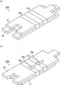
図1(a)及び図1(b)は、本発明の第一実施形態に係る保持シール材の一例を模式的に示す斜視図である。図1(a)は、保持シール材を第1のマット側から見た斜視図であり、図1(b)は、保持シール材を第2のマット側から見た斜視図である。
図1(a)及び図1(b)に示すように、本発明の第一実施形態に係る保持シール材10Aでは、所定の長手方向の長さ(以下、単に全長ともいう。図1(a)中、矢印L1、L2で示す)、幅(図1(a)中、矢印Wで示す)及び厚さ(図1(a)中、矢印Tで示す)を有する平面視略矩形の2枚のマット(第1のマット11及び第2のマット12)が積層されている。第1のマット11の全長L1は、第2のマット12の全長L2よりも短い。
以下の説明において、第1のマットと第2のマットとを特に区別する必要がない場合、単にマットと表記する。
なお、本明細書において、マットの全長とは、マットの端部に形成される凸部又は凹部の寸法を考慮しない長さである。図1(a)において、第1のマット11の全長は、矢印L1で示される長さであり、第2のマット12の全長は、矢印L2で示される長さである。
Fig.1 (a) and FIG.1 (b) are perspective views which show typically an example of the holding sealing material which concerns on 1st embodiment of this invention. FIG. 1A is a perspective view of the holding sealing material viewed from the first mat side, and FIG. 1B is a perspective view of the holding sealing material viewed from the second mat side.
As shown in FIGS. 1 (a) and 1 (b), the
In the following description, when it is not necessary to distinguish between the first mat and the second mat, they are simply referred to as a mat.
In the present specification, the total length of the mat is a length that does not take into account the dimensions of the projections or recesses formed at the ends of the mat. 1 (a), the total length of the
図1(a)及び図1(b)に示す保持シール材10Aでは、第1のマット11の長さ方向側の端部のうち、一方の端部には、凸部13aが形成されており、他方の端部には、凹部13bが形成されている。また、第2のマット12の長さ方向側の端部のうち、一方の端部には、凸部14aが形成されており、他方の端部には、凹部14bが形成されている。第1のマット11の凸部13a及び凹部13b、並びに、第2のマット12の凸部14a及び凹部14bは、後述する排ガス浄化装置を組み立てるために排ガス処理体に保持シール材10Aを巻き付けた際に、ちょうど互いに嵌合するような形状となっている。
In the
本発明の第一実施形態に係る保持シール材では、保持シール材を構成するマットは、無機繊維からなる素地マットに対してニードリング処理を施して得られるニードルマットであることが望ましい。ニードリング処理とは、ニードル等の繊維交絡手段を素地マットに対して抜き差しすることをいう。
図1(a)及び図1(b)に示す保持シール材10Aを構成する第1のマット11及び第2のマット12では、比較的平均繊維長の長い無機繊維がニードリング処理により3次元的に交絡している。第1のマット11及び第2のマット12は、長手方向に垂直な幅方向でニードリング処理されている。
なお、交絡構造を呈するために、無機繊維はある程度の平均繊維長を有しており、例えば、無機繊維の平均繊維長は、50μm〜100mmであることが望ましい。
In the holding sealing material according to the first embodiment of the present invention, the mat constituting the holding sealing material is preferably a needle mat obtained by subjecting a base mat made of inorganic fibers to needling treatment. The needling treatment refers to inserting and removing fiber entanglement means such as a needle with respect to the base mat.
In the
In addition, in order to exhibit an entanglement structure, the inorganic fiber has a certain average fiber length. For example, the average fiber length of the inorganic fiber is desirably 50 μm to 100 mm.
本発明の第一実施形態に係る保持シール材では、保持シール材の嵩高さを抑えたり、排ガス浄化装置の組み立て前の作業性を高めたりするために、保持シール材を構成するマットに、さらに有機バインダ等のバインダが含まれていてもよい。 In the holding sealing material according to the first embodiment of the present invention, in order to suppress the bulkiness of the holding sealing material or to improve the workability before assembly of the exhaust gas purification device, the mat constituting the holding sealing material is further A binder such as an organic binder may be included.
図1(a)及び図1(b)に示す保持シール材10Aでは、厚さ1.5〜15mmの2枚のマットが積層されている例を示しているが、本発明の第一実施形態に係る保持シール材において、積層するマットの数は特に限定されず、3枚以上であってもよい。複数枚のマットのうち全長が最も短いマット(以下、最短マットともいう)が排ガス処理体の周囲に巻き付けられるマットであり、次いで、最短マットより全長の長いマットが積層され、その後、順次積層されていくにつれて、マットの全長が長くなっていく。なお、図1(a)及び図1(b)に示す保持シール材10Aのように、保持シール材が2枚のマット(第1のマット11及び第2のマット12)で構成されていても、他方より全長が短い方のマット(第1のマット11)を最短マットという。
In the
図1(a)及び図1(b)に示す保持シール材10Aでは、第1のマット11と第2のマット12とが、2つの帯状体(第1の帯状体16a及び第2の帯状体17a)により結束されている。
第1の帯状体16a及び第2の帯状体17aは、それぞれ、マットの長さ方向に所定の幅(図1(a)中、矢印X1、X2で示す)を有しており、かつ、積層された第1のマット11及び第2のマット12の周囲をマットの幅方向に巻き付いている。
以下の説明において、第1の帯状体と第2の帯状体とを特に区別する必要がない場合、単に帯状体と表記する。
In the
Each of the
In the following description, when it is not necessary to distinguish between the first strip and the second strip, they are simply referred to as strips.
本発明の第一実施形態に係る保持シール材において、帯状体は、固着力を有していない材料からなる。つまり、帯状体とマットとは固着されていない。そのため、マット同士は完全に固定されず、マットを長さ方向に移動させる(ずらす)ことができる。 In the holding sealing material according to the first embodiment of the present invention, the belt-like body is made of a material having no fixing force. That is, the belt-like body and the mat are not fixed. Therefore, the mats are not completely fixed, and the mats can be moved (shifted) in the length direction.
本発明の第一実施形態に係る保持シール材において、帯状体の材料としては、固着力を有していない材料であれば特に限定されないが、例えば、紙、フィルム、布、及び、ゴム等が挙げられる。
帯状体を構成する紙は、植物繊維を原料として作られる一般的な紙の他、表面にラミネート加工等の加工が施された紙等であってもよく、その種類及び材質は特に限定されない。
帯状体を構成するフィルムは、有機フィルムであることが望ましいが、無機フィルムであってもよい。
有機フィルムは、合成樹脂等の有機材料からなることが望ましい。有機フィルムの具体例としては、ポリエチレンフィルム、ポリオレフィンフィルム、ポリ塩化ビニルフィルム、ポリビニルアルコールフィルム、ポリプロピレンフィルム、ポリエステルフィルム、ポリカーボネートフィルム、ポリスチレンフィルム、ポリアミドフィルム、又は、ポリイミドフィルム等が挙げられる。
無機フィルムは、金属又はセラミック等の無機材料からなることが望ましい。無機フィルムの具体例としては、アルミニウム、銅、鉄、銀、金等若しくはこれらの混合物からなる金属箔、又は、アルミナ若しくはシリカ等からなるセラミックフィルム等が挙げられる。
帯状体の材料の中では、入手の容易さの観点から、紙又はフィルムが望ましい。また、フィルムの中では、有機フィルムが望ましく、ポリエチレンフィルム又はポリオレフィンフィルムがより望ましい。
また、これらの複数の素材から構成されるフィルムであってもよい。
帯状体を構成するゴムは、合成ゴムであることが望ましいが、天然ゴムであってもよい。
合成ゴムの具体例としては、アクリルゴム、ニトリルゴム、スチレン−ブタジエンゴム、ブタジエンゴム、エチレン−プロピレンゴム、ウレタンゴム、又は、シリコーンゴム等が挙げられる。
帯状体を構成する布の具体例としては、植物繊維布、無機繊維布、ガラス繊維布、不織布、又は、人造繊維から作られる布等が挙げられる。
In the holding sealing material according to the first embodiment of the present invention, the material of the band-shaped body is not particularly limited as long as it is a material that does not have an adhesive force. For example, paper, film, cloth, rubber, etc. Can be mentioned.
The paper constituting the belt-like body may be a general paper made from plant fiber as a raw material, or a paper whose surface is subjected to processing such as laminating, and the type and material are not particularly limited.
The film constituting the strip is preferably an organic film, but may be an inorganic film.
The organic film is preferably made of an organic material such as a synthetic resin. Specific examples of the organic film include a polyethylene film, a polyolefin film, a polyvinyl chloride film, a polyvinyl alcohol film, a polypropylene film, a polyester film, a polycarbonate film, a polystyrene film, a polyamide film, or a polyimide film.
The inorganic film is preferably made of an inorganic material such as metal or ceramic. Specific examples of the inorganic film include a metal foil made of aluminum, copper, iron, silver, gold, or the like or a mixture thereof, or a ceramic film made of alumina, silica, or the like.
Among the strip materials, paper or film is desirable from the viewpoint of availability. Moreover, in a film, an organic film is desirable and a polyethylene film or a polyolefin film is more desirable.
Moreover, the film comprised from these several raw materials may be sufficient.
The rubber constituting the strip is preferably a synthetic rubber, but may be a natural rubber.
Specific examples of the synthetic rubber include acrylic rubber, nitrile rubber, styrene-butadiene rubber, butadiene rubber, ethylene-propylene rubber, urethane rubber, or silicone rubber.
Specific examples of the cloth constituting the strip include a vegetable fiber cloth, an inorganic fiber cloth, a glass fiber cloth, a non-woven fabric, or a cloth made from artificial fibers.
図1(a)及び図1(b)に示す保持シール材10Aにおいて、第1の帯状体16aの長手方向の端部の一方は、接着部18aにより帯状体上で接着されている。そして、第1の帯状体16aの長手方向の端部の他方は、帯状体上で接着されていない。同様に、第2の帯状体17aの長手方向の端部の一方は、接着部19aにより帯状体上で接着されている。そして、第2の帯状体17aの長手方向の端部の他方は、帯状体上で接着されていない。
第1の帯状体16aの接着部18a、及び、第2の帯状体17aの接着部19aは、どちらも、第1のマット11の主面に位置する。
なお、帯状体の長手方向とは、帯状体の幅方向に垂直な方向のことであり、図1(a)及び図1(b)において、帯状体の長手方向は、マットの幅方向と一致する。
In the
Both the
The longitudinal direction of the belt-like body is a direction perpendicular to the width direction of the belt-like body, and in FIGS. 1A and 1B, the longitudinal direction of the belt-like body coincides with the width direction of the mat. To do.
本発明の第一実施形態に係る保持シール材における帯状体の接着部について、詳細に説明する。
以下の説明では、第1の帯状体の構成について説明しているが、第2の帯状体についても同様の構成を採用することができる。
図2は、図1(a)及び図1(b)に示す保持シール材における第1の帯状体の接着部を模式的に示す断面図である。
図2に示す保持シール材10Aでは、第1の帯状体16aの長手方向の第1の端部16a1が、接着部18aにより帯状体上で接着されている。第1の帯状体16aの長手方向の第2の端部16a2は、帯状体上で接着されていない。また、接着部18aは、保持シール材10Aの一方の表面である第1のマット11の主面11aに位置する。
The adhesion part of the strip | belt-shaped body in the holding sealing material which concerns on 1st embodiment of this invention is demonstrated in detail.
In the following description, the configuration of the first strip is described, but the same configuration can be adopted for the second strip.
FIG. 2 is a cross-sectional view schematically showing an adhesive portion of the first belt-like body in the holding sealing material shown in FIGS. 1 (a) and 1 (b).
In the
本発明の第一実施形態に係る保持シール材において、帯状体の接着部の構成としては、図2に示した構成に限定されず、例えば、以下に示す構成が挙げられる。
図3(a)及び図3(b)は、本発明の第一実施形態に係る保持シール材の別の一例を模式的に示す断面図である。
図3(a)に示す保持シール材10Bでは、第1の帯状体16bの長手方向の両端(第1の端部16b1及び第2の端部16b2)が、接着部18bにより帯状体上で接着されている。また、接着部18bは、保持シール材10Bの一方の表面である第1のマット11の主面11aに位置する。
図3(b)に示す保持シール材10Cでは、第1の帯状体16cの長手方向の両端(第1の端部16c1及び第2の端部16c2)、及び、第1の端部16c1と第2の端部16c2との間の部分が、接着部18cにより帯状体上で接着されている。また、接着部18cは、保持シール材10Cの一方の表面である第1のマット11の主面11aに位置する。
図3(a)に示す第1の帯状体16bと図3(b)に示す第1の帯状体16cとでは、帯状体の両端が接着されている点は共通するが、接着部の大きさが異なっている。
In the holding sealing material according to the first embodiment of the present invention, the configuration of the adhesive portion of the belt-like body is not limited to the configuration shown in FIG. 2, and examples thereof include the following configurations.
FIG. 3A and FIG. 3B are cross-sectional views schematically showing another example of the holding sealing material according to the first embodiment of the present invention.
In the
In the holding sealing material 10C shown in FIG. 3 (b), both ends in the longitudinal direction of the
The
図2に示す保持シール材10A、図3(a)に示す保持シール材10B、及び、図3(b)に示す保持シール材10Cでは、すべて、帯状体の長手方向の第1の端部が、帯状体の長手方向の第2の端部よりも第1のマット11側に位置している。
しかしながら、本発明の第一実施形態に係る保持シール材においては、帯状体の長手方向の第2の端部が、帯状体の長手方向の第1の端部よりも第1のマット11側に位置していてもよい。また、図2に示す保持シール材10Aでは、第1の帯状体の長手方向の第1の端部が接着部により帯状体上で接着されており、第1の帯状体の長手方向の第2の端部が帯状体上で接着されていないが、本発明の第一実施形態に係る保持シール材においては、第1の帯状体の長手方向の第2の端部が接着部により帯状体上で接着されており、第1の帯状体の長手方向の第1の端部が帯状体上で接着されていなくてもよい。
In the
However, in the holding sealing material according to the first embodiment of the present invention, the second end portion in the longitudinal direction of the strip-shaped body is closer to the
本発明の第一実施形態に係る保持シール材において、第1の帯状体の接着部は、保持シール材の一方の表面である第1のマットの主面に位置する限り、特に限定されず、どの位置にあってもよい。 In the holding sealing material according to the first embodiment of the present invention, the adhesive portion of the first strip is not particularly limited as long as it is located on the main surface of the first mat that is one surface of the holding sealing material, It can be in any position.
図1(a)及び図1(b)に示す保持シール材10Aでは、第1の帯状体16aの接着部18a、及び、第2の帯状体17aの接着部19aが、どちらも同じ構成を有しており、かつ、同じ位置にある。
しかしながら、本発明の第一実施形態に係る保持シール材においては、接着部の構成はそれぞれ異なっていてもよい。また、同じ構成の接着部であっても、接着部の位置がそれぞれ異なっていてもよい。
In the
However, in the holding sealing material according to the first embodiment of the present invention, the configuration of the bonding portion may be different. Moreover, even if it is the adhesion part of the same structure, the position of an adhesion part may each differ.
本発明の第一実施形態に係る保持シール材において、帯状体に接着部を設ける方法は特に限定されず、任意の方法を用いて、帯状体の端部をその帯状体上に接着することにより接着部を形成することができる。
帯状体を接着する方法は、帯状体の材料に応じて適宜決定することができるが、例えば、糊若しくは粘着テープ等の接着剤を用いて接着する方法、ホットメルト若しくは超音波等を用いて接着する方法、又は、帯状体自身の熱接着を利用して接着する方法等が挙げられる。
In the holding sealing material according to the first embodiment of the present invention, the method for providing the adhesive portion on the strip is not particularly limited, and by adhering the end of the strip on the strip using an arbitrary method. An adhesive part can be formed.
The method for adhering the band can be appropriately determined according to the material of the band, but for example, the method of adhering using an adhesive such as glue or adhesive tape, adhering using hot melt or ultrasonic waves, etc. Or a method of bonding using the thermal bonding of the strip itself.
本発明の第一実施形態に係る保持シール材において、帯状体の数は2つに限定されず、3つ以上であってもよい。本発明の第一実施形態に係る保持シール材において、帯状体が3つ以上ある場合、それぞれの帯状体が接着部を有しており、接着部が第1のマットの主面に位置していればよい。また、接着部の構成及び位置は、互いに同じであってもよいし、異なっていてもよい。 In the holding sealing material according to the first embodiment of the present invention, the number of strips is not limited to two, and may be three or more. In the holding sealing material according to the first embodiment of the present invention, when there are three or more strips, each strip has an adhesive portion, and the adhesive portion is located on the main surface of the first mat. Just do it. Further, the configuration and position of the bonding portion may be the same or different from each other.
本発明の第一実施形態に係る保持シール材において、帯状体の1つの幅(図1(a)中、矢印X1、X2で示す長さ)は、10〜100mmであることが望ましく、20〜80mmであることがより望ましく、30〜50mmであることがさらに望ましい。
帯状体の1つの幅が10mm未満であると、帯状体が破れやすくなる。一方、帯状体の1つの幅が100mmを超えると、帯状体の数が多くなった場合に、保持シール材の面積に対する帯状体の面積が大きすぎるため、保持シール材の保持力が低下してしまう。
帯状体の構成材料が紙又はフィルム等の有機物である場合、帯状体の面積が大きくなると、保持シール材を排ガス浄化装置に用いた際、排ガスの熱によって帯状体から加熱分解する有機成分が増加すると考えられる。そして、加熱分解した流動性のある有機成分が、排ガス浄化装置を構成するマット(保持シール材)とケーシングとの間の摩擦、又は、マット(保持シール材)と排ガス処理体との間の摩擦を低下させてしまうため、保持シール材の保持力が低下すると考えられる。
In the holding sealing material according to the first embodiment of the present invention, it is desirable that one width of the belt-like body (the length indicated by arrows X 1 and X 2 in FIG. 1A) is 10 to 100 mm, It is more desirably 20 to 80 mm, and further desirably 30 to 50 mm.
When the width of one band is less than 10 mm, the band is easily broken. On the other hand, if the width of one of the strips exceeds 100 mm, when the number of strips increases, the area of the strips is too large relative to the area of the holding seal material, so the holding power of the holding seal material decreases. End up.
When the material of the strip is an organic substance such as paper or film, when the area of the strip is increased, the organic component that is thermally decomposed from the strip by the heat of the exhaust gas increases when the holding sealing material is used in the exhaust gas purification device. It is thought that. Then, the thermally decomposed fluid organic component is subjected to friction between the mat (holding seal material) and the casing constituting the exhaust gas purification device, or between the mat (holding seal material) and the exhaust gas treating body. Therefore, it is considered that the holding force of the holding sealing material is reduced.
本発明の第一実施形態に係る保持シール材において、マットの長さ方向の第1の端面に最も近い帯状体の端と、マットの長さ方向の第2の端面に最も近い帯状体の端との間の距離(図1(b)中、矢印Yで示す長さ)は、最短マットの長手方向の長さの30%以下であることが望ましく、4〜20%であることがより望ましい。
保持シール材における上記距離が30%を超えると、保持シール材(マット)の面積に対する帯状体の面積が大きすぎるため、保持シール材の保持力が低下してしまう。上述したように、帯状体の構成材料が紙又はフィルム等の有機物である場合、帯状体の面積が大きくなると、保持シール材を排ガス浄化装置に用いた際、排ガスの熱によって帯状体から加熱分解する有機成分が増加すると考えられるためである。
In the holding sealing material according to the first embodiment of the present invention, the end of the strip that is closest to the first end surface in the mat length direction and the end of the strip that is closest to the second end surface in the mat length direction Is preferably 30% or less of the length of the shortest mat in the longitudinal direction, and more preferably 4 to 20% (the length indicated by the arrow Y in FIG. 1B). .
When the distance in the holding sealing material exceeds 30%, the area of the belt-like body with respect to the area of the holding sealing material (mat) is too large, so that the holding force of the holding sealing material is reduced. As described above, when the constituent material of the strip is an organic substance such as paper or film, when the area of the strip is increased, when the holding sealing material is used in the exhaust gas purification device, the heat is decomposed from the strip by the heat of the exhaust gas. This is because the organic component is considered to increase.
本発明の第一実施形態に係る保持シール材において、マットの長さ方向の第1の端面に最も近い帯状体の端、及び、マットの長さ方向の第2の端面に最も近い帯状体の端は、マットを長さ方向に2等分する位置からマットの長さ方向の各端面に向かって、最短マットの全長の5〜45%の位置にあることが望ましく、8〜30%の位置にあることがより望ましく、10〜15%の位置にあることがさらに望ましい。
マットの長さ方向の第1の端面に最も近い帯状体の端、及び、マットの長さ方向の第2の端面に最も近い帯状体の端が、マットを長さ方向に2等分する位置からマットの長さ方向の各端面に向かって、最短マットの全長の5%未満の位置にあると、帯状体がマットの長さ方向における中央に寄り過ぎてしまい、マットの幅方向における位置ずれを防止する効果が充分に得られない。一方、マットの長さ方向の第1の端面に最も近い帯状体の端、及び、マットの長さ方向の第2の端面に最も近い帯状体の端が、マットを長さ方向に2等分する位置からマットの長さ方向の各端面に向かって、最短マットの全長の45%を超える位置にあると、帯状体がマットの長さ方向の端面に近付きすぎてしまい、帯状体がマットから外れやすくなる。
In the holding sealing material according to the first embodiment of the present invention, the end of the belt-like body closest to the first end surface in the mat length direction and the belt-like body closest to the second end surface in the mat length direction The end is preferably located at a position of 5 to 45 % of the total length of the shortest mat from a position that bisects the mat in the length direction to each end surface in the length direction of the mat, and a position of 8 to 30% It is more desirable to be in the range of 10 to 15%.
Position where the end of the strip closest to the first end face in the mat length direction and the end of the strip closest to the second end face in the mat length direction bisect the mat in the length direction If the position is less than 5% of the total length of the shortest mat from the end of the mat in the length direction of the mat, the band will be too close to the center in the length direction of the mat, and the position shift in the width direction of the mat The effect of preventing this cannot be sufficiently obtained. On the other hand, the end of the strip closest to the first end surface in the mat length direction and the end of the strip closest to the second end surface in the mat length direction bisect the mat in the length direction. If it is located at a position exceeding 45 % of the total length of the shortest mat from the position to the end surface in the length direction of the mat, the band-shaped body will be too close to the end surface in the length direction of the mat, It becomes easy to come off.
本発明の第一実施形態に係る保持シール材において、帯状体の厚さは、0.008〜1.5mmであることが望ましい。
帯状体の厚さが0.008mm未満であると、帯状体が破れやすくなり、マットを結束しにくくなる。一方、帯状体の厚さが1.5mmを超えると、排ガス浄化装置を製造する際の保持シール材を巻き付ける工程において邪魔になったり、他の箇所に引っ掛かりやすくなる。その結果、排ガス浄化装置の製造効率が低下しやすくなる。
In the holding sealing material according to the first embodiment of the present invention, the thickness of the strip is preferably 0.008 to 1.5 mm.
When the thickness of the strip is less than 0.008 mm, the strip is easily broken and the mats are not easily bound. On the other hand, when the thickness of the belt-like body exceeds 1.5 mm, it becomes an obstacle in the process of winding the holding sealing material when manufacturing the exhaust gas purifying apparatus, and it becomes easy to get caught in other places. As a result, the manufacturing efficiency of the exhaust gas purification device is likely to be reduced.
本発明の第一実施形態に係る保持シール材において、マットの幅方向における帯状体の接着部の長さ(図2中、矢印Zで示す)は、特に限定されないが、マットの幅の3%以上であることが望ましく、5〜15%であることがより望ましい。
マットの幅方向における帯状体の接着部の長さが、マットの幅の3%未満であると、接着部が小さすぎるため、帯状体の端部が剥がれやすくなる。
In the holding sealing material according to the first embodiment of the present invention, the length (indicated by an arrow Z in FIG. 2) of the adhesive portion of the strip in the width direction of the mat is not particularly limited, but is 3% of the width of the mat. It is desirable to be above, and it is more desirable that it is 5 to 15%.
If the length of the bonded portion of the strip in the width direction of the mat is less than 3% of the width of the mat, the bonded portion is too small and the end of the strip is easily peeled off.
本発明の第一実施形態に係る保持シール材において、図2に示すように、帯状体の長手方向の第2の端部が帯状体上で接着されていない場合、帯状体の長手方向の第2の端部から接着部までの長さは、マットの幅の30%以下であることが望ましく、5〜20%であることがより望ましい。
帯状体の長手方向の第2の端部から接着部までの長さが、マットの幅の30%を超えると、排ガス浄化装置を製造する際の保持シール材を巻き付ける工程において邪魔になったり、他の箇所に引っ掛かりやすくなる。その結果、排ガス浄化装置の製造効率が低下しやすくなる。
また、本発明の第一実施形態に係る保持シール材において、帯状体の長手方向の第1の端部が帯状体上で接着されていない場合も同様である。
In the holding sealing material according to the first embodiment of the present invention, as shown in FIG. 2, when the second end in the longitudinal direction of the strip is not bonded on the strip, the first in the longitudinal direction of the strip The length from the
When the length from the second end portion in the longitudinal direction of the belt-like body to the bonded portion exceeds 30% of the width of the mat, it becomes an obstacle in the process of winding the holding sealing material when manufacturing the exhaust gas purification device, It becomes easy to get caught in other places. As a result, the manufacturing efficiency of the exhaust gas purification device is likely to be reduced.
Further, in the holding sealing material according to the first embodiment of the present invention, the same applies to the case where the first end portion in the longitudinal direction of the strip is not bonded on the strip.
本発明の第一実施形態に係る保持シール材において、帯状体の接着部は、図1(a)、図1(b)及び図2に示すように、マットの長さ方向及び幅方向に一様に帯状体上に形成されていることが望ましい。つまり、帯状体の接着部は、平面視略矩形状に形成されていることが望ましい。帯状体の端部をしっかりと接着することができるためである。
しかしながら、本発明の第一実施形態に係る保持シール材において、帯状体の接着部の平面視形状は特に限定されず、略円形状、略楕円形状、又は、略多角形状等、任意の形状であってよい。また、帯状体の接着部は、平面視略ドーナツ形状等のように、一部に接着部が形成されていない部分があってもよい。
In the holding sealing material according to the first embodiment of the present invention, as shown in FIG. 1 (a), FIG. 1 (b), and FIG. It is desirable that it be formed on the belt-like body. That is, it is desirable that the adhesive portion of the belt-like body is formed in a substantially rectangular shape in plan view. This is because the end of the belt-like body can be firmly bonded.
However, in the holding sealing material according to the first embodiment of the present invention, the shape of the bonding portion of the band-like body in plan view is not particularly limited, and may be any shape such as a substantially circular shape, a substantially elliptical shape, or a substantially polygonal shape. It may be. Further, the adhesive part of the belt-like body may have a part where the adhesive part is not formed in part, such as a substantially donut shape in a plan view.
本発明の第一実施形態に係る保持シール材の製造方法の一例を説明する。
まず、紡糸法により、無機繊維を絡み合わせて作製した素地マットを打ち抜き、長さの異なる素地マットを用意する。
そして、長さの異なる複数の素地マットに対して、必要に応じてニードリング処理を施して、保持シール材を製造するために必要な複数のマットを作製する。
素地マットでは、無機繊維が紡糸工程を経て緩く絡み合っている。この緩く絡み合った無機繊維に対してニードリング処理を施すことで、より複雑に無機繊維が絡み合い、バインダが存在しなくてもある程度の形状維持が可能な交絡構造を有するマットとすることができる。
An example of the manufacturing method of the holding sealing material which concerns on 1st embodiment of this invention is demonstrated.
First, a base mat produced by intertwining inorganic fibers by a spinning method is punched to prepare base mats having different lengths.
Then, a plurality of base mats having different lengths are subjected to needling treatment as necessary to produce a plurality of mats necessary for manufacturing the holding sealing material.
In the base mat, inorganic fibers are loosely entangled through a spinning process. By applying the needling treatment to the loosely entangled inorganic fibers, the mat can be made into a mat having an entangled structure capable of maintaining a certain shape even if the inorganic fibers are entangled more complicatedly and no binder is present.
ここで、排ガス処理体に巻き付けられることになる最短マットの全長は、排ガス処理体の円周長に対応していることから、まず、最短マットの全長を排ガス処理体の円周長に基づいて決定する。次いで、最短マットの外側に位置することになるマットの全長は、排ガス処理体の直径に、巻き付けた際の最短マットの厚さを加えた直径に対する円周長に対応することから、この円周長を求めて最短マットの外側に位置するマットの全長を決定する。これらの手順を順に繰り返し、積層させる複数のマットのそれぞれの全長を決定していく。 Here, since the total length of the shortest mat to be wound around the exhaust gas treatment body corresponds to the circumferential length of the exhaust gas treatment body, first, the total length of the shortest mat is based on the circumferential length of the exhaust gas treatment body. decide. Next, since the total length of the mat that will be located outside the shortest mat corresponds to the circumference of the diameter of the exhaust gas treatment body plus the thickness of the shortest mat when wound, this circumference The total length of the mat located outside the shortest mat is determined by determining the length. These procedures are repeated in order to determine the total length of each of the plurality of mats to be stacked.
続いて、ニードリング処理を施したマットに、必要に応じてバインダを付着させる。マットにバインダを付着させることで、無機繊維同士の交絡構造をより強固なものとすることができるとともに、マットの嵩高さを抑えることができる。 Subsequently, a binder is attached to the mat subjected to the needling treatment as necessary. By attaching the binder to the mat, the entangled structure of the inorganic fibers can be made stronger and the bulk of the mat can be suppressed.
バインダとしては、アクリル系ラテックスやゴム系ラテックス等を水に分散させて調製したエマルジョンを用いることができる。このバインダをスプレー等を用いてマット全体に均一に吹きかけて、バインダをマットに付着させる。 As the binder, an emulsion prepared by dispersing acrylic latex or rubber latex in water can be used. This binder is sprayed uniformly on the entire mat using a spray or the like, and the binder is adhered to the mat.
その後、バインダ中の水分を除去するために、マットを乾燥させる。乾燥条件としては、例えば、95〜150℃で1〜30分間乾燥させればよい。乾燥工程を経ることでマットを作製することができる。 Thereafter, the mat is dried to remove moisture in the binder. As a drying condition, for example, it may be dried at 95 to 150 ° C. for 1 to 30 minutes. A mat can be produced through a drying process.
本発明の第一実施形態では、長さの異なる複数のマットを作製し、複数のマットを長さが長くなる順で、又は、短くなる順で積層していく。積層させるマットの数は、保持シール材に求められる保持力や保温性能に応じて変更すればよい。代表的な積層手順としては、最も全長の長いマットを初めに敷き、積層するにつれて全長が短くなるように、順次マットを積層していく。積層させるマットの相対位置は、積層される全長の短いマットがその下にある全長の長いマットのどちらかの端から飛び出さないような位置に積層してもよく、互いに長手方向にずれて全長の長いマットのどちらかの端から飛び出すような位置に積層してもよい。 In the first embodiment of the present invention, a plurality of mats having different lengths are manufactured, and the plurality of mats are stacked in the order in which the lengths are increased or decreased. The number of mats to be laminated may be changed according to the holding power and heat holding performance required for the holding sealing material. As a typical lamination procedure, a mat having the longest length is laid first, and the mats are sequentially laminated so that the overall length becomes shorter as the layers are laminated. The relative positions of the mats to be stacked may be stacked so that the short mat with the entire length does not jump out from either end of the long mat underneath. You may laminate in the position which jumps out from either end of a long mat.
次に、積層した複数のマットを帯状体により結束する。
例えば、一定の幅を有する長い紙製のテープを用意しておき、複数枚のマットの周囲に巻き付けた後にテープを切断し、テープの端部の少なくとも一方をテープ上で接着する工程を帯状体の数だけ繰り返す方法等が挙げられる。テープを接着する方法としては、上述したように、糊若しくは粘着テープ等の接着剤を用いて接着する方法、ホットメルト若しくは超音波等を用いて接着する方法、又は、帯状体自身の熱接着を利用して接着する方法等が挙げられる。
以上の方法により、本発明の第一実施形態に係る保持シール材を製造することができる。
Next, the plurality of laminated mats are bound by a strip.
For example, a process of preparing a long paper tape having a certain width, winding the tape around a plurality of mats, cutting the tape, and bonding at least one end of the tape on the tape The method of repeating as many as these is mentioned. As a method of adhering the tape, as described above, a method of bonding using an adhesive such as glue or adhesive tape, a method of bonding with a hot-melt or ultrasonic or the like, or, the thermal bonding of the strip itself The method of using and adhering is mentioned.
By the above method, the holding sealing material according to the first embodiment of the present invention can be manufactured.
次に、本発明の第一実施形態に係る保持シール材を用いた本発明の第一実施形態に係る排ガス浄化装置について説明する。
図4(a)は、本発明の第一実施形態に係る排ガス浄化装置の一例を模式的に示す斜視図であり、図4(b)は、図4(a)に示す排ガス浄化装置のA−A線断面図である。
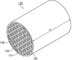
図4(a)及び図4(b)に示すように、本発明の第一実施形態に係る排ガス浄化装置100は、多数のセル131がセル壁132を隔てて長手方向に並設された柱状の排ガス処理体130と、排ガス処理体130を収容するケーシング120と、排ガス処理体130とケーシング120との間に配設され、排ガス処理体130を保持する保持シール材110とから構成されている。
ケーシング120の端部には、必要に応じて、内燃機関から排出された排ガスを導入する導入管と排ガス浄化装置を通過した排ガスが外部に排出される排出管とが接続されることになる。
なお、図4(a)及び図4(b)に示す排ガス浄化装置100では、図4(b)に示すように、排ガス処理体130として、各々のセルにおけるいずれか一方が封止材133によって目封じされたハニカムフィルタを用いている。
Next, the exhaust gas purifying apparatus according to the first embodiment of the present invention using the holding sealing material according to the first embodiment of the present invention will be described.
FIG. 4 (a) is a perspective view schematically showing an example of the exhaust gas purifying apparatus according to the first embodiment of the present invention, and FIG. 4 (b) is an A of the exhaust gas purifying apparatus shown in FIG. 4 (a). FIG.
As shown in FIGS. 4 (a) and 4 (b), the exhaust
An end of the
In addition, in the exhaust
図4(a)及び図4(b)に示す排ガス浄化装置100では、保持シール材110として、図1(a)、図1(b)及び図2に示した保持シール材10Aが用いられている。
本発明の第一実施形態に係る排ガス浄化装置では、保持シール材として、本発明の第一実施形態に係る任意の保持シール材を用いることができる。
In the exhaust
In the exhaust gas purifying apparatus according to the first embodiment of the present invention, any holding sealing material according to the first embodiment of the present invention can be used as the holding sealing material.
上述した構成を有する排ガス浄化装置100を排ガスが通過する場合について、図4(b)を用いて以下に説明する。
図4(b)に示すように、内燃機関から排出され、排ガス浄化装置100に流入した排ガス(図4(b)中、排ガスをGで示し、排ガスの流れを矢印で示す)は、排ガス処理体(ハニカムフィルタ)130の排ガス流入側端面130aに開口した一のセル131に流入し、セル131を隔てるセル壁132を通過する。この際、排ガス中のPMがセル壁132で捕集され、排ガスが浄化されることとなる。浄化された排ガスは、排ガス流出側端面130bに開口した他のセル131から流出し、外部に排出される。
A case where the exhaust gas passes through the exhaust
As shown in FIG. 4 (b), the exhaust gas discharged from the internal combustion engine and flowing into the exhaust gas purification apparatus 100 (in FIG. 4 (b), the exhaust gas is indicated by G and the flow of the exhaust gas is indicated by an arrow) is the exhaust gas treatment. It flows into one
次に、図4(a)及び図4(b)に示す排ガス浄化装置100を構成する排ガス処理体(ハニカムフィルタ)及びケーシングについて説明する。
なお、保持シール材110の構成については、本発明の第一実施形態に係る保持シール材として既に説明しているので省略する。
Next, the exhaust gas treatment body (honeycomb filter) and the casing constituting the exhaust
In addition, about the structure of the
まず、排ガス浄化装置を構成する排ガス処理体について説明する。
図5は、本発明の第一実施形態に係る排ガス浄化装置を構成する排ガス処理体の一例を模式的に示す斜視図である。
図5に示すように、排ガス処理体(ハニカムフィルタ)130は、主に多孔質セラミックからなり、その形状は略円柱状である。また、ハニカムフィルタ130の外周には、ハニカムフィルタ130の外周部を補強したり、形状を整えたり、ハニカムフィルタ130の断熱性を向上させたりする目的で、外周コート層134が設けられている。
なお、ハニカムフィルタ130の内部の構成については、上述した本発明の第一実施形態に係る排ガス浄化装置の説明で既に述べた通りである(図4(b)参照)。
First, the exhaust gas treatment body constituting the exhaust gas purification apparatus will be described.
FIG. 5 is a perspective view schematically showing an example of the exhaust gas treating body constituting the exhaust gas purifying apparatus according to the first embodiment of the present invention.
As shown in FIG. 5, the exhaust gas treating body (honeycomb filter) 130 is mainly made of porous ceramic and has a substantially cylindrical shape. In addition, an outer
The internal configuration of the
次に、排ガス浄化装置を構成するケーシングについて説明する。
図6は、本発明の第一実施形態に係る排ガス浄化装置を構成するケーシングの一例を模式的に示す斜視図である。
図6に示すケーシング120は、主にステンレス等の金属からなり、その形状は、略円筒状である。また、その内径は、ハニカムフィルタ130の端面の直径とハニカムフィルタ130に巻付けられた状態の保持シール材10Aの厚さとを合わせた長さより若干短くなっており、その長さは、ハニカムフィルタ130の長手方向(図5中、矢印aの方向)における長さと略同一となっている。
Next, the casing which comprises an exhaust gas purification apparatus is demonstrated.
FIG. 6 is a perspective view schematically showing an example of a casing constituting the exhaust gas purifying apparatus according to the first embodiment of the present invention.
The
続いて、本発明の第一実施形態に係る排ガス浄化装置の製造方法について説明する。
図7(a)、図7(b)及び図7(c)は、本発明の第一実施形態に係る排ガス浄化装置の製造方法の一例を模式的に示す斜視図である。
図7(a)、図7(b)及び図7(c)では、本発明の第一実施形態に係る排ガス浄化装置の製造方法の一例として、図4(a)及び図4(b)に示した排ガス浄化装置100の製造方法について説明する。
Then, the manufacturing method of the exhaust gas purification apparatus which concerns on 1st embodiment of this invention is demonstrated.
7 (a), 7 (b) and 7 (c) are perspective views schematically showing an example of the method for manufacturing the exhaust gas purifying apparatus according to the first embodiment of the present invention.
7 (a), 7 (b) and 7 (c), FIGS. 4 (a) and 4 (b) show an example of the method for manufacturing the exhaust gas purifying apparatus according to the first embodiment of the present invention. A method for manufacturing the illustrated exhaust
まず、図7(a)及び図7(b)に示すように、図1(a)、図1(b)及び図2に示した保持シール材10Aを排ガス処理体(ハニカムフィルタ)130の周囲に巻き付けることにより、巻付体(保持シール材が巻き付けられた排ガス処理体)150を作製する巻き付け工程を行う。
巻き付け工程では、従来公知の方法により作製した略円柱形状の排ガス処理体130の外周に、上記工程で製造した保持シール材10Aを凸部13aと凹部13bとが嵌合するように、かつ、凸部14aと凹部14bとが嵌合するようにして巻き付ける。
この際、図7(a)に示すように、保持シール材10Aの第1の帯状体16aの接着部18a及び第2の帯状体17aの接着部19aが位置する側のマットの主面、つまり、第1のマット11の主面を排ガス処理体130に当接させるように、保持シール材10Aを排ガス処理体130の周囲に巻き付ける(図7(a)では、第1の帯状体16aの接着部18a及び第2の帯状体17aの接着部19aを図示していない)。
その結果、図7(b)に示す巻付体150を作製することができる。
First, as shown in FIGS. 7 (a) and 7 (b), the
In the winding step, the holding
At this time, as shown in FIG. 7A, the main surface of the mat on the side where the
As a result, the
次に、図7(c)に示すように、作製した巻付体150を、所定の大きさを有する略円筒状であって、主に金属等からなるケーシング120に収容する収容工程を行う。
収容後にシール材が圧縮して所定の反発力(すなわち、排ガス処理体を保持する力)を発揮するために、ケーシング120の内径は、保持シール材10Aを巻き付けた排ガス処理体130の保持シール材10Aの厚さを含めた最外径より少し小さくなっている。
以上の方法により、図4(a)及び図4(b)に示した排ガス浄化装置100を製造することができる。
Next, as shown in FIG. 7C, an accommodating process is performed in which the produced wound
In order to exhibit a predetermined repulsive force (that is, a force for holding the exhaust gas treating body) by compressing the sealing material after the housing, the inner diameter of the
By the above method, the exhaust
収容工程において、巻付体をケーシングに収容する方法としては、例えば、圧入方式(スタッフィング方式)、サイジング方式(スウェージング方式)、及び、クラムシェル方式等が挙げられる。
圧入方式(スタッフィング方式)では、圧入治具等を用いて、ケーシングの内部の所定の位置まで巻付体を圧入する。サイジング方式(スウェージング方式)では、巻付体をケーシングの内部に挿入した後、ケーシングの内径を縮めるように外周側から圧縮する。クラムシェル方式では、ケーシングを、第1のケーシング及び第2のケーシングの2つの部品に分離可能な形状としておき、巻付体を第1のケーシング上に載置した後に第2のケーシングを被せて密封する。
巻付体をケーシングに収容する方法の中では、圧入方式(スタッフィング方式)又はサイジング方式(スウェージング方式)が望ましい。圧入方式(スタッフィング方式)又はサイジング方式(スウェージング方式)では、ケーシングとして2つの部品を用いる必要がないため、製造工程の数を少なくすることができるからである。
Examples of a method for housing the wound body in the casing in the housing step include a press-fitting method (stuffing method), a sizing method (swaging method), and a clamshell method.
In the press-fitting method (stuffing method), the wound body is press-fitted to a predetermined position inside the casing using a press-fitting jig or the like. In the sizing method (swaging method), the wound body is inserted into the casing and then compressed from the outer peripheral side so as to reduce the inner diameter of the casing. In the clamshell method, the casing is shaped so as to be separable into two parts, a first casing and a second casing, and the wound body is placed on the first casing and then covered with the second casing. Seal.
Of the methods for accommodating the wound body in the casing, a press-fitting method (stuffing method) or a sizing method (swaging method) is desirable. This is because in the press-fitting method (stuffing method) or the sizing method (swaging method), it is not necessary to use two parts as the casing, so the number of manufacturing processes can be reduced.
また、本発明の第一実施形態に係る排ガス浄化装置の製造方法では、巻き付け工程の後、収容工程の前に、保持シール材を構成する帯状体を除去する除去工程を行ってもよい。
例えば、保持シール材を排ガス処理体の周囲に巻き付けた後、粘着テープ等を用いて保持シール材及び排ガス処理体の位置を固定すれば、帯状体は不要となる。そのため、はさみ及びカッター等の切断治具を用いることによって、帯状体を除去することができる。
帯状体の構成材料が紙又はフィルム等の有機物である場合、帯状体を除去することにより、排ガス浄化装置を使用する際、排ガスの熱によって帯状体から加熱分解する有機成分の量を低減することができる。
以上より、本発明の第一実施形態に係る排ガス浄化装置の製造方法では、製造後の排ガス浄化装置に、帯状体が残っていてもよいし、残っていなくてもよい。
Moreover, in the manufacturing method of the exhaust gas purifying apparatus according to the first embodiment of the present invention, after the winding step, the removing step of removing the strips constituting the holding sealing material may be performed before the accommodating step.
For example, if the holding sealing material is wound around the exhaust gas treating body and then the positions of the holding sealing material and the exhaust gas treating body are fixed using an adhesive tape or the like, the belt-like body becomes unnecessary. Therefore, the strip-shaped body can be removed by using a cutting jig such as scissors and a cutter.
When the constituent material of the strip is an organic substance such as paper or film, by removing the strip, the amount of organic components thermally decomposed from the strip by the heat of exhaust gas is reduced when the exhaust gas purification device is used. Can do.
As mentioned above, in the manufacturing method of the exhaust gas purification apparatus according to the first embodiment of the present invention, the band-like body may or may not remain in the exhaust gas purification apparatus after manufacture.
以下に、本発明の第一実施形態に係る保持シール材、排ガス浄化装置、及び、排ガス浄化装置の製造方法の作用効果について列挙する。
(1)本実施形態の保持シール材では、複数枚のマットが、固着力を有していない帯状体により結束されている。従って、マット同士が固定されていないため、排ガス処理体の周囲に巻き付ける際、マットを長さ方向にずらすことができる。そのため、マットの位置がずれている場合であっても、保持シール材を排ガス処理体の周囲に巻き付ける際に、マット間の相対的な位置の微調整を行うことができる。その結果、マットの端面(マットの長さ方向側の端面)を隙間なく嵌合することができる。
Below, it enumerates about the effect of the manufacturing method of the holding | maintenance sealing material, exhaust gas purification apparatus, and exhaust gas purification apparatus which concern on 1st embodiment of this invention.
(1) In the holding sealing material of the present embodiment, a plurality of mats are bound together by a strip-like body that does not have an adhesive force. Therefore, since the mats are not fixed, the mats can be shifted in the length direction when wound around the exhaust gas treating body. Therefore, even when the mats are misaligned, the relative position between the mats can be finely adjusted when the holding sealing material is wound around the exhaust gas treating body. As a result, it is possible to fit the end face of the mat (end face on the length direction side of the mat) without a gap.
(2)本実施形態の保持シール材では、複数枚のマットが、マットの長さ(マットの長手方向の長さ)に対して一定の幅を有する帯状体によって結束されている。従って、マットの幅方向における位置ずれを防止することができる。 (2) In the holding sealing material of the present embodiment, a plurality of mats are bound together by a belt-like body having a certain width with respect to the mat length (length in the longitudinal direction of the mat). Accordingly, it is possible to prevent the positional deviation in the width direction of the mat.
(3)本実施形態の保持シール材では、固着力を有していない帯状体が用いられている。そのため、接着テープ等を用いて複数枚のマットを固定する場合と違って、有機成分の使用量を低減することができる。 (3) In the holding sealing material of the present embodiment, a belt-like body that does not have an adhering force is used. Therefore, unlike the case where a plurality of mats are fixed using an adhesive tape or the like, the amount of organic components used can be reduced.
(4)本実施形態の保持シール材では、複数枚のマットを積層することに失敗した場合であっても、帯状体を切断等によって除去すればやり直すことができ、マットに傷が付く等の問題はない。一方、特許文献1に記載の従来の保持シール材では、複数枚のマットを積層することに失敗した場合、マットにはミシン跡が残るため、マットを再利用することが困難である。このように、本実施形態の保持シール材では、保持シール材を製造するために必要な材料の無駄を低減することができる。 (4) In the holding sealing material of this embodiment, even if it fails to laminate a plurality of mats, it can be redone if the strip is removed by cutting, etc. No problem. On the other hand, in the conventional holding sealing material described in Patent Document 1, if a plurality of mats fail to be laminated, the traces of the sewing machine remain on the mats, making it difficult to reuse the mats. Thus, in the holding sealing material of the present embodiment, it is possible to reduce the waste of materials necessary for manufacturing the holding sealing material.
(5)本実施形態の保持シール材では、上記複数枚のマットは、2つ以上の上記帯状体により結束されている。
複数枚のマットが2箇所以上で固定されていると、マットの幅方向における位置ずれをより防止することができる。なぜなら、各帯状体から保持シール材の両端部を見たときには、少なくとも一方の端部側に固定端が存在することから、マットの幅方向における位置ずれの自由度が大きく規制されることになるためである。
(5) In the holding sealing material of the present embodiment, the plurality of mats are bound together by two or more strips.
When a plurality of mats are fixed at two or more locations, it is possible to further prevent displacement in the mat width direction. This is because when the both end portions of the holding sealing material are viewed from each band-like body, the fixed end is present on at least one end side, so that the degree of freedom of displacement in the width direction of the mat is greatly restricted. Because.
(6)本実施形態の保持シール材では、上記帯状体の長手方向の端部の少なくとも一方が、接着部により帯状体上で接着されている。
例えば、一定の幅を有する長いテープを用意しておき、複数枚のマットの周囲に巻き付けた後にテープを切断し、テープの端部の少なくとも一方をテープ上で接着することによって、帯状体を作製することができる。従って、結束するマットの枚数(厚さ)に応じた帯状体を容易に作製することができる。
(6) In the holding sealing material of the present embodiment, at least one of the end portions in the longitudinal direction of the band-shaped body is bonded on the band-shaped body by the bonding portion.
For example, by preparing a long tape having a certain width, winding the tape around a plurality of mats, cutting the tape, and bonding at least one end of the tape on the tape to produce a belt-like body can do. Accordingly, it is possible to easily produce a band-like body corresponding to the number of mats to be bound (thickness).
(7)本実施形態の排ガス浄化装置、及び、排ガス浄化装置の製造方法では、保持シール材として本実施形態の保持シール材が用いられているため、保持シール材を排ガス処理体の周囲に隙間なく巻き付けることができる。従って、排ガス浄化装置における排ガスの漏れ及び耐久性の低下を防止することができる。 (7) In the exhaust gas purifying apparatus and the manufacturing method of the exhaust gas purifying apparatus of the present embodiment, since the holding seal material of the present embodiment is used as the holding seal material, the holding seal material is spaced around the exhaust gas treatment body. It can be wound without. Therefore, it is possible to prevent leakage of exhaust gas and deterioration of durability in the exhaust gas purification device.
(8)本実施形態の排ガス浄化装置、及び、排ガス浄化装置の製造方法では、上記保持シール材を構成する帯状体の長手方向の端部の少なくとも一方が接着部により帯状体上で接着されており、上記排ガス処理体に当接する側のマットの主面に位置する。
帯状体の接着部が排ガス処理体に当接する側のマットの主面に位置していると、保持シール材が巻き付けられた排ガス処理体をケーシングに収容する際、接着部がケーシングに引っ掛からないため、保持シール材が巻き付けられた排ガス処理体をケーシングに容易に収容することができる。
(8) In the exhaust gas purifying apparatus and the manufacturing method of the exhaust gas purifying apparatus of the present embodiment, at least one of the end portions in the longitudinal direction of the band-shaped body constituting the holding sealing material is bonded on the band-shaped body by the bonding portion. And located on the main surface of the mat on the side in contact with the exhaust gas treating body.
When the adhesive part of the belt-like body is located on the main surface of the mat on the side in contact with the exhaust gas treatment body, the adhesive part is not caught on the casing when the exhaust gas treatment body around which the holding sealing material is wound is accommodated in the casing. The exhaust gas treating body around which the holding sealing material is wound can be easily accommodated in the casing.
(第二実施形態)
以下、本発明の保持シール材、排ガス浄化装置、及び、排ガス浄化装置の製造方法の一実施形態である第二実施形態について説明する。
(Second embodiment)
Hereinafter, a second embodiment which is an embodiment of the method for manufacturing the holding sealing material, the exhaust gas purifying apparatus, and the exhaust gas purifying apparatus of the present invention will be described.
まず、本発明の第二実施形態に係る保持シール材について説明する。
本発明の第二実施形態に係る保持シール材は、無機繊維からなるマットが複数枚積層されており、上記複数枚のマットは、固着力を有していない、2つ以上の帯状体により結束されている。また、保持シール材を構成する帯状体の長手方向の端部の少なくとも一方は、接着部により帯状体上で接着されている。そして、帯状体の接着部は、上記保持シール材を用いて排ガス浄化装置を製造した際、排ガス処理体に当接する側と反対側のマットの主面に位置している。
First, the holding sealing material according to the second embodiment of the present invention will be described.
The holding sealing material according to the second embodiment of the present invention is formed by laminating a plurality of mats made of inorganic fibers, and the plurality of mats are bound by two or more strips having no fixing force. Has been. Further, at least one of the end portions in the longitudinal direction of the band-shaped body constituting the holding sealing material is bonded on the band-shaped body by the bonding portion. When the exhaust gas purifying apparatus is manufactured using the holding sealing material, the adhesive portion of the belt-like body is located on the main surface of the mat opposite to the side in contact with the exhaust gas treatment body.
図8(a)及び図8(b)は、本発明の第二実施形態に係る保持シール材の一例を模式的に示す斜視図である。図8(a)は、保持シール材を第1のマット側から見た斜視図であり、図8(b)は、保持シール材を第2のマット側から見た斜視図である。
図8(a)及び図8(b)に示す保持シール材20Aでは、第1のマット21と第2のマット22とが、2つの帯状体(第1の帯状体26a及び第2の帯状体27a)により結束されている。
FIG. 8A and FIG. 8B are perspective views schematically showing an example of the holding sealing material according to the second embodiment of the present invention. FIG. 8A is a perspective view of the holding sealing material viewed from the first mat side, and FIG. 8B is a perspective view of the holding sealing material viewed from the second mat side.
In the
図8(a)及び図8(b)に示す保持シール材20Aにおいて、第1の帯状体26aの長手方向の端部の一方は、接着部28aにより帯状体上で接着されている。そして、第1の帯状体26aの長手方向の端部の他方は、帯状体上で接着されていない。同様に、第2の帯状体27aの長手方向の端部の一方は、接着部29aにより帯状体上で接着されている。そして、第2の帯状体27aの長手方向の端部の他方は、帯状体上で接着されていない。
第1の帯状体26aの接着部28a、及び、第2の帯状体27aの接着部29aは、どちらも、第2のマット22の主面に位置する。
In the
Both the
本発明の第二実施形態に係る保持シール材においては、帯状体の接着部の位置が、本発明の第一実施形態に係る保持シール材と異なるだけである。
そのため、帯状体の接着部の構成としては、図2、図3(a)及び図3(b)に示した構成をはじめとする、本発明の第一実施形態に係る保持シール材で説明した構成と同様の構成を挙げることができる。
In the holding sealing material according to the second embodiment of the present invention, the position of the adhesive portion of the belt-like body is only different from that of the holding sealing material according to the first embodiment of the present invention.
Therefore, the configuration of the adhesive portion of the belt-shaped body has been described with the holding sealing material according to the first embodiment of the present invention, including the configuration shown in FIGS. 2, 3 (a) and 3 (b). A configuration similar to the configuration can be given.
本発明の第二実施形態に係る保持シール材において、図8(b)に示すように、帯状体の長手方向の一方の端部が帯状体上で接着されていない場合、帯状体の長手方向の一方の端部から接着部までの長さは、マットの幅の5〜20%であることが望ましい。
本発明の第二実施形態に係る保持シール材では、帯状体の長手方向の一方の端部が帯状体上で接着されていないと、保持シール材を排ガス処理体の周囲に巻き付けた後、容易に帯状体を剥がすことができる。
帯状体の長手方向の一方の端部から接着部までの長さが、マットの幅の5%未満であると、保持シール材を排ガス処理体の周囲に巻き付けた後に帯状体を剥がしにくくなる。一方、帯状体の長手方向の一方の端部から接着部までの長さが、マットの幅の20%を超えると、排ガス浄化装置を製造する際の保持シール材を巻き付ける工程において邪魔になったり、他の箇所に引っ掛かりやすくなる。その結果、排ガス浄化装置の製造効率が低下しやすくなる。
なお、保持シール材を排ガス処理体の周囲に巻き付けた後に、帯状体を除去しない場合には、帯状体の両端同士が接着部に接着されていても問題ない。
また、本発明の第二実施形態に係る保持シール材において、帯状体の長手方向の他方の端部が帯状体上で接着されていない場合も同様である。
In the holding sealing material according to the second embodiment of the present invention, as shown in FIG. 8 (b), when one end portion in the longitudinal direction of the strip is not bonded on the strip, the longitudinal direction of the strip It is desirable that the length from one end of the adhesive to the bonded portion is 5 to 20% of the width of the mat.
In the holding sealing material according to the second embodiment of the present invention, if one end in the longitudinal direction of the belt-like body is not bonded on the belt-like body, the holding sealing material is easily wound around the exhaust gas treatment body. The strip can be peeled off.
If the length from one end of the strip in the longitudinal direction to the bonded portion is less than 5% of the width of the mat, it is difficult to peel the strip after the holding sealing material is wound around the exhaust gas treatment body. On the other hand, if the length from one end of the strip in the longitudinal direction to the bonded portion exceeds 20% of the width of the mat, it may be an obstacle in the process of winding the holding sealing material when manufacturing the exhaust gas purification device. , Get caught in other places. As a result, the manufacturing efficiency of the exhaust gas purification device is likely to be reduced.
In addition, after the holding sealing material is wound around the exhaust gas treating body, when the strip is not removed, there is no problem even if both ends of the strip are bonded to the bonding portion.
Further, in the holding sealing material according to the second embodiment of the present invention, the same applies to the case where the other end in the longitudinal direction of the strip is not bonded on the strip.
本発明の第二実施形態に係る保持シール材のその他の構成は、本発明の第一実施形態に係る保持シール材と同様であるので、その詳細な説明を省略する。 Since the other structure of the holding sealing material according to the second embodiment of the present invention is the same as that of the holding sealing material according to the first embodiment of the present invention, detailed description thereof is omitted.
次に、本発明の第二実施形態に係る保持シール材を用いた本発明の第二実施形態に係る排ガス浄化装置について説明する。
図9は、本発明の第二実施形態に係る排ガス浄化装置の一例を模式的に示す斜視図である。
図9に示すように、本発明の第二実施形態に係る排ガス浄化装置200は、排ガス処理体(ハニカムフィルタ)230と、排ガス処理体230を収容するケーシング220と、排ガス処理体230とケーシング220との間に配設され、排ガス処理体230を保持する保持シール材210とから構成されている。
Next, an exhaust gas purifying apparatus according to the second embodiment of the present invention using the holding sealing material according to the second embodiment of the present invention will be described.
FIG. 9 is a perspective view schematically showing an example of the exhaust gas purifying apparatus according to the second embodiment of the present invention.
As shown in FIG. 9, the exhaust
図9に示す排ガス浄化装置200では、保持シール材210として、図8(a)及び図8(b)に示した保持シール材20Aが用いられている。
本発明の第二実施形態に係る排ガス浄化装置では、保持シール材として、本発明の第二実施形態に係る任意の保持シール材を用いることができる。
In the exhaust
In the exhaust gas purification apparatus according to the second embodiment of the present invention, any holding sealing material according to the second embodiment of the present invention can be used as the holding sealing material.
本発明の第二実施形態に係る排ガス浄化装置のその他の構成は、本発明の第一実施形態に係る排ガス浄化装置と同様であるので、その詳細な説明を省略する。 Since the other structure of the exhaust gas purification apparatus which concerns on 2nd embodiment of this invention is the same as that of the exhaust gas purification apparatus which concerns on 1st embodiment of this invention, the detailed description is abbreviate | omitted.
続いて、本発明の第二実施形態に係る排ガス浄化装置の製造方法について説明する。
図10(a)、図10(b)及び図10(c)は、本発明の第二実施形態に係る排ガス浄化装置の製造方法の一例を模式的に示す斜視図である。
図10(a)、図10(b)及び図10(c)では、本発明の第二実施形態に係る排ガス浄化装置の製造方法の一例として、図9に示した排ガス浄化装置200の製造方法について説明する。
Then, the manufacturing method of the exhaust gas purification apparatus which concerns on 2nd embodiment of this invention is demonstrated.
10 (a), 10 (b) and 10 (c) are perspective views schematically showing an example of a method for manufacturing an exhaust gas purifying apparatus according to the second embodiment of the present invention.
10 (a), 10 (b), and 10 (c), as an example of the method for manufacturing the exhaust gas purifying apparatus according to the second embodiment of the present invention, the method for manufacturing the exhaust
まず、図10(a)及び図10(b)に示すように、図8(a)及び図8(b)に示した保持シール材20Aを排ガス処理体(ハニカムフィルタ)230の周囲に巻き付けることにより、巻付体(保持シール材が巻き付けられた排ガス処理体)250を作製する巻き付け工程を行う。
この際、図10(a)に示すように、保持シール材20Aの第1の帯状体26aの接着部28a及び第2の帯状体27aの接着部29aが位置する側と反対側のマットの主面、つまり、第1のマット21の主面を排ガス処理体230に当接させるように、保持シール材20Aを排ガス処理体230の周囲に巻き付ける(図10(a)では、第2の帯状体27aの接着部29aを図示していない)。
その結果、図10(b)に示す巻付体250を作製することができる。
First, as shown in FIGS. 10 (a) and 10 (b), the
At this time, as shown in FIG. 10 (a), the main mat on the side opposite to the side where the
As a result, the
次に、図10(c)に示すように、作製した巻付体250を、所定の大きさを有する略円筒状であって、主に金属等からなるケーシング220に収容する収容工程を行う。
以上の方法により、図9に示した排ガス浄化装置200を製造することができる。
Next, as shown in FIG. 10 (c), an accommodating process is performed in which the produced wound
The exhaust
また、本発明の第二実施形態に係る排ガス浄化装置の製造方法では、巻き付け工程の後、収容工程の前に、保持シール材を構成する帯状体を除去する除去工程を行ってもよい。
本発明の第二実施形態に係る排ガス浄化装置の製造方法では、帯状体の接着部が、保持シール材の最も外側のマットに位置している。そのため、接着部を剥がすことによって帯状体を容易に除去することができる。さらに、帯状体の長手方向の一方の端部が帯状体上で接着されていないと、接着されていない端部から帯状体を容易に除去することができる。
もちろん、はさみ及びカッター等の切断治具を用いることによって、帯状体を除去してもよい。
以上より、本発明の第二実施形態に係る排ガス浄化装置の製造方法では、製造後の排ガス浄化装置に、帯状体が残っていてもよいし、残っていなくてもよい。
Moreover, in the manufacturing method of the exhaust gas purifying apparatus according to the second embodiment of the present invention, after the winding step, the removing step of removing the strips constituting the holding sealing material may be performed before the accommodating step.
In the method for manufacturing an exhaust gas purifying apparatus according to the second embodiment of the present invention, the adhesive portion of the belt-like body is located on the outermost mat of the holding sealing material. Therefore, the strip-shaped body can be easily removed by peeling off the adhesive portion. Furthermore, if one end of the strip in the longitudinal direction is not bonded on the strip, the strip can be easily removed from the unbonded end.
Of course, the band-shaped body may be removed by using a cutting jig such as scissors and a cutter.
As mentioned above, in the manufacturing method of the exhaust gas purifying apparatus according to the second embodiment of the present invention, the band-like body may or may not remain in the exhaust gas purifying apparatus after manufacture.
本発明の第二実施形態に係る排ガス浄化装置の製造方法は、上記の点を除いて、本発明の第一実施形態に係る排ガス浄化装置の製造方法と同様であるので、その詳細な説明を省略する。 Since the manufacturing method of the exhaust gas purifying apparatus according to the second embodiment of the present invention is the same as the manufacturing method of the exhaust gas purifying apparatus according to the first embodiment of the present invention except for the above points, a detailed description thereof will be given. Omitted.
本発明の第二実施形態では、本発明の第一実施形態において説明した効果(1)〜(7)を発揮することができるとともに、以下の効果を発揮することができる。
(9)本実施形態の排ガス浄化装置、及び、排ガス浄化装置の製造方法では、上記保持シール材を構成する帯状体の長手方向の端部の少なくとも一方が接着部により帯状体上で接着されており、上記帯状体の接着部は、上記排ガス処理体に当接する側と反対側のマットの主面に位置する。
帯状体の接着部が排ガス処理体に当接する側と反対側のマットの主面に位置していると、はさみ等の道具を用いることなく、接着部を剥がすことによって帯状体を容易に除去することができる。
In the second embodiment of the present invention, the effects (1) to (7) described in the first embodiment of the present invention can be exhibited, and the following effects can be exhibited.
(9) In the exhaust gas purifying apparatus and the manufacturing method of the exhaust gas purifying apparatus of the present embodiment, at least one of the end portions in the longitudinal direction of the band-shaped body constituting the holding sealing material is bonded on the band-shaped body by the bonding portion. And the adhesion part of the said strip | belt-shaped body is located in the main surface of the mat | matte on the opposite side to the side contact | abutted to the said waste gas processing body.
If the adhesive part of the belt is located on the main surface of the mat opposite to the side in contact with the exhaust gas treatment body, the belt can be easily removed by peeling off the adhesive without using a tool such as scissors. be able to.
(第三実施形態)
以下、本発明の保持シール材、排ガス浄化装置、及び、排ガス浄化装置の製造方法の一実施形態である第三実施形態について説明する。
(Third embodiment)
Hereinafter, a third embodiment, which is an embodiment of the method for manufacturing the holding sealing material, the exhaust gas purification device, and the exhaust gas purification device of the present invention, will be described.
まず、本発明の第三実施形態に係る保持シール材について説明する。
本発明の第三実施形態に係る保持シール材は、無機繊維からなるマットが複数枚積層されており、上記複数枚のマットは、固着力を有していない、2つ以上の帯状体により結束されている。また、保持シール材を構成する帯状体の長手方向の端部の少なくとも一方は、接着部により帯状体上で接着されている。そして、帯状体の接着部は、マットの幅方向側の第1の端面又は第2の端面に位置する。
First, the holding sealing material according to the third embodiment of the present invention will be described.
The holding sealing material according to the third embodiment of the present invention is formed by laminating a plurality of mats made of inorganic fibers, and the plurality of mats are bound by two or more strips that do not have an adhesive force. Has been. Further, at least one of the end portions in the longitudinal direction of the band-shaped body constituting the holding sealing material is bonded on the band-shaped body by the bonding portion. And the adhesion part of a strip | belt-shaped body is located in the 1st end surface or 2nd end surface of the width direction side of a mat | matte.
図11は、本発明の第三実施形態に係る保持シール材の一例を模式的に示す斜視図である。
図11に示す保持シール材30Aでは、第1のマット31と第2のマット32とが、2つの帯状体(第1の帯状体36a及び第2の帯状体37a)により結束されている。
FIG. 11 is a perspective view schematically showing an example of the holding sealing material according to the third embodiment of the present invention.
In the
図11に示す保持シール材30Aにおいて、第1の帯状体36aの長手方向の端部の一方は、接着部38aにより帯状体上で接着されている。そして、第1の帯状体36aの長手方向の端部の他方は、帯状体上で接着されていない。同様に、第2の帯状体37aの長手方向の端部の一方は、接着部39aにより帯状体上で接着されている。そして、第2の帯状体37aの長手方向の端部の他方は、帯状体上で接着されていない。
第1の帯状体36aの接着部38a、及び、第2の帯状体37aの接着部39aは、どちらも、マットの幅方向側の第1の端面に位置する。
In the
Both the
本発明の第三実施形態に係る保持シール材における帯状体の接着部について、詳細に説明する。
以下の説明では、第1の帯状体の構成について説明しているが、第2の帯状体についても同様の構成を採用することができる。
図12は、図11に示す保持シール材における第1の帯状体の接着部を模式的に示す断面図である。
図12に示す保持シール材30Aでは、第1の帯状体36aの長手方向の第1の端部36a1が、接着部38aにより帯状体上で接着されている。第1の帯状体36aの長手方向の第2の端部36a2は、帯状体上で接着されていない。また、接着部38aは、保持シール材30Aの一方の側面であるマットの幅方向側の第1の端面(第1のマット31の幅方向側の第1の端面31b及び第2のマット32の幅方向側の第1の端面32b)に位置する。
The adhesion part of the strip | belt shaped body in the holding sealing material which concerns on 3rd embodiment of this invention is demonstrated in detail.
In the following description, the configuration of the first strip is described, but the same configuration can be adopted for the second strip.
FIG. 12 is a cross-sectional view schematically showing an adhesive portion of the first strip in the holding sealing material shown in FIG.
In the
本発明の第三実施形態に係る保持シール材において、帯状体の接着部の構成としては、図12に示した構成に限定されず、例えば、以下に示す構成が挙げられる。
図13(a)及び図13(b)は、本発明の第三実施形態に係る保持シール材の別の一例を模式的に示す断面図である。
図13(a)に示す保持シール材30Bでは、第1の帯状体36bの長手方向の両端(第1の端部36b1及び第2の端部36b2)が、接着部38bにより帯状体上で接着されている。また、接着部38bは、保持シール材30Bの一方の側面であるマットの幅方向側の第1の端面(第1のマット31の幅方向側の第1の端面31b及び第2のマット32の幅方向側の第1の端面32b)に位置する。
図13(b)に示す保持シール材30Cでは、第1の帯状体36cの長手方向の両端(第1の端部36c1及び第2の端部36c2)、及び、第1の端部36c1と第2の端部36c2との間の部分が、接着部38cにより帯状体上で接着されている。また、接着部38cは、保持シール材30Cの一方の側面であるマットの幅方向側の第1の端面(第1のマット31の幅方向側の第1の端面31b及び第2のマット32の幅方向側の第1の端面32b)に位置する。
図13(a)に示す第1の帯状体36bと図13(b)に示す第1の帯状体36cとでは、帯状体の両端が接着されている点は共通するが、接着部の大きさが異なっている。
In the holding sealing material according to the third embodiment of the present invention, the configuration of the adhesive portion of the belt-like body is not limited to the configuration shown in FIG. 12, and examples thereof include the following configurations.
FIGS. 13A and 13B are cross-sectional views schematically showing another example of the holding sealing material according to the third embodiment of the present invention.
In the
13 In the
The first belt-
図12に示す保持シール材30A、図13(a)に示す保持シール材30B、及び、図13(b)に示す保持シール材30Cでは、すべて、帯状体の長手方向の第1の端部が、帯状体の長手方向の第2の端部よりも第1のマット31及び第2のマット32側に位置している。
しかしながら、本発明の第三実施形態に係る保持シール材においては、帯状体の長手方向の第2の端部が、帯状体の長手方向の第1の端部よりも第1のマット31及び第2のマット32側に位置していてもよい。また、図12に示す保持シール材30Aでは、第1の帯状体の長手方向の第1の端部が接着部により帯状体上で接着されており、第1の帯状体の長手方向の第2の端部が帯状体上で接着されていないが、本発明の第三実施形態に係る保持シール材においては、第1の帯状体の長手方向の第2の端部が接着部により帯状体上で接着されており、第1の帯状体の長手方向の第1の端部が帯状体上で接着されていなくてもよい。
In the
However, in the holding sealing material according to the third embodiment of the present invention, the second end portion in the longitudinal direction of the strip-shaped body is more in contact with the
本発明の第三実施形態に係る保持シール材において、第1の帯状体の接着部は、保持シール材の一方の側面であるマットの幅方向側の第1の端面ではなく、マットの幅方向側の第1の端面と対向する第2の端面に位置していてもよい。
また、本発明の第三実施形態に係る保持シール材において、第1の帯状体の接着部は、マットの幅方向側の第1の端面又は第2の端面に位置する限り、特に限定されず、どの位置にあってもよい。
In the holding sealing material according to the third embodiment of the present invention, the adhesive portion of the first belt-like body is not the first end face on the mat width direction side which is one side surface of the holding sealing material, but the mat width direction. You may be located in the 2nd end surface facing the 1st end surface of the side.
Further, in the holding sealing material according to the third embodiment of the present invention, the adhesive portion of the first belt-like body is not particularly limited as long as it is located on the first end surface or the second end surface on the width direction side of the mat. , It can be in any position.
図11に示す保持シール材30Aでは、第1の帯状体36aの接着部38a、及び、第2の帯状体37aの接着部39aが、どちらも同じ構成を有しており、かつ、同じ位置にある。
しかしながら、本発明の第三実施形態に係る保持シール材においては、接着部の構成はそれぞれ異なっていてもよい。また、同じ構成の接着部であっても、接着部の位置がそれぞれ異なっていてもよい。さらに、マットの幅方向側の第1の端面に接着部が位置する帯状体と、マットの幅方向側の第2の端面に接着部が位置する帯状体とが混在していてもよい。
In the
However, in the holding sealing material according to the third embodiment of the present invention, the configuration of the bonding portion may be different. Moreover, even if it is the adhesion part of the same structure, the position of an adhesion part may each differ. Furthermore, a belt-like body in which the adhesive portion is located on the first end surface on the width direction side of the mat and a belt-like body in which the adhesive portion is located on the second end surface on the width direction side of the mat may be mixed.
本発明の第三実施形態に係る保持シール材において、図12に示すように、帯状体の長手方向の一方の端部が帯状体上で接着されていない場合、帯状体の長手方向の一方の端部から接着部までの長さは、マットの幅の5〜10%であることが望ましい。
本発明の第三実施形態に係る保持シール材では、帯状体の長手方向の一方の端部が帯状体上で接着されていないと、保持シール材を排ガス処理体の周囲に巻き付けた後、容易に帯状体を剥がすことができる。
帯状体の長手方向の一方の端部から接着部までの長さが、マットの幅の5%未満であると、保持シール材を排ガス処理体の周囲に巻き付けた後に帯状体を剥がしにくくなる。一方、帯状体の長手方向の一方の端部から接着部までの長さが、マットの幅の10%を超えると、排ガス浄化装置を製造する際の保持シール材を巻き付ける工程において邪魔になったり、他の箇所に引っ掛かりやすくなる。その結果、排ガス浄化装置の製造効率が低下しやすくなる。
なお、保持シール材を排ガス処理体の周囲に巻き付けた後に、帯状体を除去しない場合には、帯状体の両端同士が接着部に接着されていても問題ない。
また、本発明の第三実施形態に係る保持シール材において、帯状体の長手方向の他方の端部が帯状体上で接着されていない場合も同様である。
In the holding sealing material according to the third embodiment of the present invention, as shown in FIG. 12, when one end in the longitudinal direction of the strip is not bonded on the strip, The length from the end portion to the bonded portion is desirably 5 to 10% of the width of the mat.
In the holding sealing material according to the third embodiment of the present invention, if one end portion in the longitudinal direction of the belt-like body is not adhered on the belt-like body, the holding sealing material is easily wound around the exhaust gas treatment body. The strip can be peeled off.
If the length from one end of the strip in the longitudinal direction to the bonded portion is less than 5% of the width of the mat, it is difficult to peel the strip after the holding sealing material is wound around the exhaust gas treatment body. On the other hand, if the length from one end of the strip in the longitudinal direction to the bonded portion exceeds 10% of the width of the mat, it may be an obstacle in the process of winding the holding sealing material when manufacturing the exhaust gas purification device. , Get caught in other places. As a result, the manufacturing efficiency of the exhaust gas purification device is likely to be reduced.
In addition, after the holding sealing material is wound around the exhaust gas treating body, when the strip is not removed, there is no problem even if both ends of the strip are bonded to the bonding portion.
Further, in the holding sealing material according to the third embodiment of the present invention, the same applies to the case where the other end in the longitudinal direction of the strip is not bonded on the strip.
本発明の第三実施形態に係る保持シール材のその他の構成は、本発明の第一実施形態に係る保持シール材と同様であるので、その詳細な説明を省略する。 Since the other structure of the holding sealing material according to the third embodiment of the present invention is the same as that of the holding sealing material according to the first embodiment of the present invention, detailed description thereof is omitted.
次に、本発明の第三実施形態に係る保持シール材を用いた本発明の第三実施形態に係る排ガス浄化装置について説明する。
図14は、本発明の第三実施形態に係る排ガス浄化装置の一例を模式的に示す斜視図である。
図14に示すように、本発明の第三実施形態に係る排ガス浄化装置300は、排ガス処理体(ハニカムフィルタ)330と、排ガス処理体330を収容するケーシング320と、排ガス処理体330とケーシング320との間に配設され、排ガス処理体330を保持する保持シール材310とから構成されている。
Next, an exhaust gas purification apparatus according to a third embodiment of the present invention using the holding sealing material according to the third embodiment of the present invention will be described.
FIG. 14 is a perspective view schematically showing an example of the exhaust gas purifying apparatus according to the third embodiment of the present invention.
As shown in FIG. 14, the exhaust
図14に示す排ガス浄化装置300では、保持シール材310として、図11及び図12に示した保持シール材30Aが用いられている。
本発明の第三実施形態に係る排ガス浄化装置では、保持シール材として、本発明の第三実施形態に係る任意の保持シール材を用いることができる。
In the exhaust
In the exhaust gas purifying apparatus according to the third embodiment of the present invention, any holding sealing material according to the third embodiment of the present invention can be used as the holding sealing material.
本発明の第三実施形態に係る排ガス浄化装置のその他の構成は、本発明の第一実施形態に係る排ガス浄化装置と同様であるので、その詳細な説明を省略する。 Since the other structure of the exhaust gas purification apparatus which concerns on 3rd embodiment of this invention is the same as that of the exhaust gas purification apparatus which concerns on 1st embodiment of this invention, the detailed description is abbreviate | omitted.
続いて、本発明の第三実施形態に係る排ガス浄化装置の製造方法について説明する。
図15(a)、図15(b)及び図15(c)は、本発明の第三実施形態に係る排ガス浄化装置の製造方法の一例を模式的に示す斜視図である。
図15(a)、図15(b)及び図15(c)では、本発明の第三実施形態に係る排ガス浄化装置の製造方法の一例として、図14に示した排ガス浄化装置300の製造方法について説明する。
Then, the manufacturing method of the exhaust gas purification apparatus which concerns on 3rd embodiment of this invention is demonstrated.
15 (a), 15 (b) and 15 (c) are perspective views schematically showing an example of a method for manufacturing an exhaust gas purifying apparatus according to the third embodiment of the present invention.
15 (a), 15 (b) and 15 (c), as an example of the method for manufacturing the exhaust gas purifying apparatus according to the third embodiment of the present invention, the method for manufacturing the exhaust
まず、図15(a)及び図15(b)に示すように、図11及び図12に示した保持シール材30Aを排ガス処理体(ハニカムフィルタ)330の周囲に巻き付けることにより、巻付体(保持シール材が巻き付けられた排ガス処理体)350を作製する巻き付け工程を行う。
この際、図15(a)に示すように、保持シール材30Aの第1のマット31の主面を排ガス処理体330に当接させるように、保持シール材30Aを排ガス処理体330の周囲に巻き付ける。
その結果、図15(b)に示す巻付体350を作製することができる。
First, as shown in FIGS. 15A and 15B, the holding sealing material 30 </ b> A shown in FIGS. 11 and 12 is wound around the exhaust gas treatment body (honeycomb filter) 330, so that a wound body ( A winding step for producing the exhaust
At this time, as shown in FIG. 15A, the holding sealing material 30 </ b> A is placed around the exhaust
As a result, the
次に、図15(c)に示すように、作製した巻付体350を、所定の大きさを有する略円筒状であって、主に金属等からなるケーシング320に収容する収容工程を行う。
以上の方法により、図14に示した排ガス浄化装置300を製造することができる。
Next, as shown in FIG. 15C, an accommodating process is performed in which the produced wound
The exhaust
また、本発明の第三実施形態に係る排ガス浄化装置の製造方法では、巻き付け工程の後、収容工程の前に、保持シール材を構成する帯状体を除去する除去工程を行ってもよい。
本発明の第三実施形態に係る排ガス浄化装置の製造方法では、帯状体の接着部が、マットの幅方向の第1の端面又は第2の端面に位置している。そのため、接着部を剥がすことによって帯状体を容易に除去することができる。さらに、帯状体の長手方向の一方の端部が帯状体上で接着されていないと、接着されていない端部から帯状体を容易に除去することができる。
もちろん、はさみ及びカッター等の切断治具を用いることによって、帯状体を除去してもよい。
以上より、本発明の第三実施形態に係る排ガス浄化装置の製造方法では、製造後の排ガス浄化装置に、帯状体が残っていてもよいし、残っていなくてもよい。
Moreover, in the manufacturing method of the exhaust gas purifying apparatus according to the third embodiment of the present invention, after the winding step, the removing step of removing the strips constituting the holding sealing material may be performed before the accommodating step.
In the method for manufacturing an exhaust gas purification apparatus according to the third embodiment of the present invention, the adhesive portion of the belt-like body is located on the first end surface or the second end surface in the width direction of the mat. Therefore, the strip-shaped body can be easily removed by peeling off the adhesive portion. Furthermore, if one end of the strip in the longitudinal direction is not bonded on the strip, the strip can be easily removed from the unbonded end.
Of course, the band-shaped body may be removed by using a cutting jig such as scissors and a cutter.
From the above, in the method for manufacturing an exhaust gas purification apparatus according to the third embodiment of the present invention, the strip-shaped body may or may not remain in the exhaust gas purification apparatus after manufacture.
本発明の第三実施形態に係る排ガス浄化装置の製造方法は、上記の点を除いて、本発明の第一実施形態に係る排ガス浄化装置の製造方法と同様であるので、その詳細な説明を省略する。 Since the manufacturing method of the exhaust gas purifying apparatus according to the third embodiment of the present invention is the same as the manufacturing method of the exhaust gas purifying apparatus according to the first embodiment of the present invention except for the above points, a detailed description thereof will be given. Omitted.
本発明の第三実施形態では、本発明の第一実施形態において説明した効果(1)〜(7)を発揮することができるとともに、以下の効果を発揮することができる。
(10)本実施形態の排ガス浄化装置の製造方法では、上記保持シール材を構成する帯状体の長手方向の端部の少なくとも一方が接着部により帯状体上で接着されており、上記帯状体の接着部は、マットの幅方向側の第1の端面又は第2の端面に位置する。そのため、接着部を剥がすことによって帯状体を容易に除去することができる。
In the third embodiment of the present invention, the effects (1) to (7) described in the first embodiment of the present invention can be exhibited, and the following effects can be exhibited.
(10) In the method for manufacturing the exhaust gas purifying apparatus of the present embodiment, at least one of the longitudinal ends of the band-shaped body constituting the holding sealing material is bonded on the band-shaped body by the bonding portion, The adhesive portion is located on the first end surface or the second end surface on the width direction side of the mat. Therefore, the strip-shaped body can be easily removed by peeling off the adhesive portion.
(第四実施形態)
以下、本発明の保持シール材、排ガス浄化装置、及び、排ガス浄化装置の製造方法の一実施形態である第四実施形態について説明する。
(Fourth embodiment)
Hereinafter, a fourth embodiment, which is an embodiment of the manufacturing method of the holding sealing material, the exhaust gas purification device, and the exhaust gas purification device of the present invention, will be described.
まず、本発明の第四実施形態に係る保持シール材について説明する。
本発明の第四実施形態に係る保持シール材は、無機繊維からなるマットが複数枚積層されており、上記複数枚のマットは、固着力を有していない、1つの帯状体により結束されている。
上記の点を除いて、本発明の第四実施形態に係る保持シール材は、本発明の第一実施形態〜第三実施形態のいずれかに係る保持シール材と同様の構成を有する。
First, the holding sealing material according to the fourth embodiment of the present invention will be described.
In the holding sealing material according to the fourth embodiment of the present invention, a plurality of mats made of inorganic fibers are laminated, and the plurality of mats are bundled by a single band-like body having no fixing force. Yes.
Except for the above points, the holding sealing material according to the fourth embodiment of the present invention has the same configuration as the holding sealing material according to any one of the first to third embodiments of the present invention.
図16は、本発明の第四実施形態に係る保持シール材の一例を模式的に示す斜視図である。
図16に示す保持シール材40Aでは、第1のマット41と第2のマット42とが、1つの帯状体46aにより結束されている。
FIG. 16 is a perspective view schematically showing an example of the holding sealing material according to the fourth embodiment of the present invention.
In the
図16に示す保持シール材40Aにおいて、帯状体46aの長手方向の端部の一方は、接着部48aにより帯状体上で接着されている。そして、帯状体46aの長手方向の端部の他方は、帯状体上で接着されていない。帯状体46aの接着部48aは、第1のマット41の主面に位置する。
In the
本発明の第四実施形態に係る保持シール材においては、帯状体の数が1つであるので、「マットの長さ方向の第1の端面に最も近い帯状体の端と、マットの長さ方向の第2の端面に最も近い帯状体の端との間の距離」は、帯状体の1つの幅(図16中、矢印X3で示す長さ)と一致する。
本発明の第四実施形態に係る保持シール材において、帯状体の1つの幅は、10〜100mmであることが望ましく、20〜80mmであることがより望ましく、30〜50mmであることがさらに望ましい。
帯状体の1つの幅が10mm未満であると、複数枚のマットを固定する幅が小さすぎるため、マットの幅方向における位置ずれを防止する効果が充分に得られない。一方、帯状体の1つの幅が100mmを超えると、保持シール材の面積に対する帯状体の面積が大きすぎるため、保持シール材の保持力が低下してしまう。
In the holding sealing material according to the fourth embodiment of the present invention, since the number of strips is one, “the end of the strip that is closest to the first end surface in the mat length direction and the length of the mat” the distance between the end closest strip on the second end face of the direction "(in FIG. 16, the length indicated by an arrow X 3) 1 single width of the strip coincides with.
In the holding sealing material according to the fourth embodiment of the present invention, the width of one of the strips is preferably 10 to 100 mm, more preferably 20 to 80 mm, and still more preferably 30 to 50 mm. .
If the width of one of the strips is less than 10 mm, the width for fixing a plurality of mats is too small, so that the effect of preventing the displacement in the width direction of the mats cannot be sufficiently obtained. On the other hand, if the width of one of the belt-like bodies exceeds 100 mm, the area of the belt-like body with respect to the area of the holding sealing material is too large, so that the holding force of the holding sealing material is reduced.
本発明の第四実施形態に係る保持シール材においては、帯状体の数が1つである点が、本発明の第一実施形態〜第三実施形態に係る保持シール材と異なる。
本発明の第四実施形態に係る保持シール材のその他の構成は、本発明の第一実施形態〜第三実施形態のいずれかに係る保持シール材と同様である。そのため、その詳細な説明を省略する。
The holding sealing material according to the fourth embodiment of the present invention is different from the holding sealing material according to the first embodiment to the third embodiment of the present invention in that the number of strips is one.
Other configurations of the holding sealing material according to the fourth embodiment of the present invention are the same as those of the holding sealing material according to any one of the first to third embodiments of the present invention. Therefore, the detailed description is abbreviate | omitted.
本発明の第四実施形態に係る排ガス浄化装置は、本発明の第四実施形態に係る保持シール材が用いられている点を除いて、本発明の第一実施形態〜第三実施形態のいずれかに係る排ガス浄化装置と同様の構成を有している。そのため、その詳細な説明を省略する。 The exhaust gas purifying apparatus according to the fourth embodiment of the present invention is any of the first to third embodiments of the present invention except that the holding sealing material according to the fourth embodiment of the present invention is used. It has the same configuration as the exhaust gas purifying apparatus. Therefore, the detailed description is abbreviate | omitted.
本発明の第四実施形態に係る排ガス浄化装置の製造方法は、本発明の第四実施形態に係る保持シール材を用いる点を除いて、本発明の第一実施形態〜第三実施形態のいずれかに係る排ガス浄化装置の製造方法と同様の構成を有している。そのため、その詳細な説明を省略する。 The method for manufacturing an exhaust gas purification apparatus according to the fourth embodiment of the present invention is any of the first to third embodiments of the present invention except that the holding sealing material according to the fourth embodiment of the present invention is used. It has the same configuration as the manufacturing method of the exhaust gas purifying apparatus. Therefore, the detailed description is abbreviate | omitted.
本発明の第四実施形態では、本発明の第一実施形態〜第三実施形態において説明した効果(1)〜(4)及び(6)〜(10)を発揮することができる。 In the fourth embodiment of the present invention, the effects (1) to (4) and (6) to (10) described in the first to third embodiments of the present invention can be exhibited.
(第五実施形態)
以下、本発明の保持シール材、排ガス浄化装置、及び、排ガス浄化装置の製造方法の一実施形態である第五実施形態について説明する。
(Fifth embodiment)
Hereinafter, a fifth embodiment which is an embodiment of a holding sealing material, an exhaust gas purification device, and an exhaust gas purification device manufacturing method of the present invention will be described.
まず、本発明の第五実施形態に係る保持シール材について説明する。
本発明の第五実施形態に係る保持シール材では、マットの幅方向側の第1の端面及び第2の端面に、帯状体を固定することができるように構成された溝部が形成されている。
上記の点を除いて、本発明の第五実施形態に係る保持シール材は、本発明の第一実施形態〜第四実施形態のいずれかに係る保持シール材と同様の構成を有する。
First, the holding sealing material according to the fifth embodiment of the present invention will be described.
In the holding sealing material according to the fifth embodiment of the present invention, the groove portion configured to fix the belt-like body is formed on the first end surface and the second end surface on the width direction side of the mat. .
Except for the above points, the holding sealing material according to the fifth embodiment of the present invention has the same configuration as the holding sealing material according to any one of the first to fourth embodiments of the present invention.
図17は、本発明の第五実施形態に係る保持シール材の一例を模式的に示す斜視図である。
図17に示す保持シール材50Aでは、第1のマット51と第2のマット52とが、2つの帯状体(第1の帯状体56a及び第2の帯状体57a)により結束されている。
FIG. 17 is a perspective view schematically showing an example of the holding sealing material according to the fifth embodiment of the present invention.
In the
図17に示す保持シール材50Aにおいて、マットの幅方向側の第1の端面には、第1の帯状体56aを固定することができるように構成された溝部53a、及び、第2の帯状体57aを固定することができるように構成された溝部54aが形成されている。同様に、マットの幅方向側の第2の端面には、第1の帯状体56aを固定することができるように構成された溝部53b、及び、第2の帯状体57aを固定することができるように構成された溝部54bが形成されている。
In the
本発明の第五実施形態に係る保持シール材において、帯状体を固定することができるように構成された溝部の幅(マットの長さ方向における長さ)は、帯状体の幅と同じ長さであってもよいが、帯状体の幅よりも長いことが望ましい。この場合、帯状体と溝部との間に隙間が存在するため、マットを長さ方向に移動させる(ずらす)ことができる。
具体的には、帯状体を固定することができるように構成された溝部の幅は、帯状体の幅の101〜110%であることが望ましい。
上記溝部の幅が、帯状体の幅の101%未満であると、帯状体と溝部との間の隙間が小さいため、マットが長さ方向に移動しにくくなる。その結果、保持シール材を排ガス処理体の周囲に巻き付ける際に、マットの端面にずれが生じやすくなる。一方、上記溝部の幅が、帯状体の幅の110%を超えると、マットの有効面積が減少するため、保持シール材の保持力を損なうこととなる。
In the holding sealing material according to the fifth embodiment of the present invention, the width of the groove (length in the mat length direction) configured to be able to fix the belt-like body is the same as the width of the belt-like body. However, it is desirable that the width is longer than the width of the belt-like body. In this case, since there is a gap between the strip and the groove, the mat can be moved (shifted) in the length direction.
Specifically, it is desirable that the width of the groove portion configured to fix the belt-like body is 101 to 110% of the width of the belt-like body.
When the width of the groove is less than 101% of the width of the strip, the mat is difficult to move in the length direction because the gap between the strip and the groove is small. As a result, when the holding sealing material is wound around the exhaust gas treating body, the end face of the mat is likely to be displaced. On the other hand, if the width of the groove portion exceeds 110% of the width of the belt-like body, the effective area of the mat is reduced, so that the holding force of the holding sealing material is impaired.
本発明の第五実施形態に係る保持シール材において、帯状体を固定することができるように構成された溝部の深さ(マットの幅方向における長さ)は、0.1〜5mmであることが望ましく、0.2〜2mmであることがより望ましい。
上記溝部の深さが0.1mm未満であると、溝部を設ける効果を充分に得ることができない。一方、上記溝部の深さが5mmを超えると、帯状体がマットに食い込みすぎるため、マットが長さ方向に移動しにくくなる。
In the holding sealing material according to the fifth embodiment of the present invention, the depth of the groove portion (length in the width direction of the mat) configured to be able to fix the belt-shaped body is 0.1 to 5 mm. Is desirable, and it is more desirable that it is 0.2-2 mm.
If the depth of the groove is less than 0.1 mm, the effect of providing the groove cannot be sufficiently obtained. On the other hand, when the depth of the groove portion exceeds 5 mm, the belt-like body bites into the mat so that the mat is difficult to move in the length direction.
本発明の第五実施形態に係る保持シール材においては、帯状体を固定することができるように構成された溝部が形成されている点が、本発明の第一実施形態〜第四実施形態に係る保持シール材と異なる。
本発明の第五実施形態に係る保持シール材のその他の構成は、本発明の第一実施形態〜第四実施形態のいずれかに係る保持シール材と同様である。そのため、その詳細な説明を省略する。
In the holding sealing material according to the fifth embodiment of the present invention, the point that the groove portion configured to fix the belt-like body is formed is the first embodiment to the fourth embodiment of the present invention. Different from the holding sealing material.
Other configurations of the holding sealing material according to the fifth embodiment of the present invention are the same as those of the holding sealing material according to any one of the first to fourth embodiments of the present invention. Therefore, the detailed description is abbreviate | omitted.
本発明の第五実施形態に係る保持シール材を製造するためには、溝部が形成された所定の形状に打ち抜いたマットを用いてもよいし、本発明の第一実施形態〜第四実施形態のいずれかに係る保持シール材で用いるマットの端面を研削することにより溝部を形成してもよい。
以上のようなマットを用いることにより、本発明の第五実施形態に係る保持シール材を製造することができる。
In order to manufacture the holding sealing material according to the fifth embodiment of the present invention, a mat punched into a predetermined shape formed with a groove may be used, or the first to fourth embodiments of the present invention. You may form a groove part by grinding the end surface of the mat | matte used with the holding | maintenance sealing material which concerns on either.
By using the mat as described above, the holding sealing material according to the fifth embodiment of the present invention can be manufactured.
本発明の第五実施形態に係る排ガス浄化装置は、本発明の第五実施形態に係る保持シール材が用いられている点を除いて、本発明の第一実施形態〜第四実施形態のいずれかに係る排ガス浄化装置と同様の構成を有している。そのため、その詳細な説明を省略する。 The exhaust gas purifying apparatus according to the fifth embodiment of the present invention is any of the first embodiment to the fourth embodiment of the present invention, except that the holding sealing material according to the fifth embodiment of the present invention is used. It has the same configuration as the exhaust gas purifying apparatus. Therefore, the detailed description is abbreviate | omitted.
本発明の第五実施形態に係る排ガス浄化装置の製造方法は、本発明の第五実施形態に係る保持シール材を用いる点を除いて、本発明の第一実施形態〜第四実施形態のいずれかに係る排ガス浄化装置の製造方法と同様の構成を有している。そのため、その詳細な説明を省略する。 The exhaust gas purifying apparatus manufacturing method according to the fifth embodiment of the present invention is any of the first to fourth embodiments of the present invention except that the holding sealing material according to the fifth embodiment of the present invention is used. It has the same configuration as the manufacturing method of the exhaust gas purifying apparatus. Therefore, the detailed description is abbreviate | omitted.
本発明の第五実施形態では、本発明の第一実施形態〜第三実施形態において説明した効果(1)〜(10)を発揮することができるとともに、以下の効果を発揮することができる。
(11)本実施形態の保持シール材では、上記マットの幅方向側の第1の端面及び第2の端面には、上記帯状体を固定することができるように構成された溝部が形成されている。
マットの幅方向側の端面に溝部が形成されていると、上記溝部により帯状体の位置を固定することができるため、マットの幅方向における位置ずれをより防止することができる。
In the fifth embodiment of the present invention, the effects (1) to (10) described in the first to third embodiments of the present invention can be exhibited, and the following effects can be exhibited.
(11) In the holding sealing material of the present embodiment, the first end surface and the second end surface on the width direction side of the mat are formed with a groove portion configured to be able to fix the belt-like body. Yes.
If the groove is formed on the end surface on the width direction side of the mat, the position of the belt-like body can be fixed by the groove, so that the displacement of the mat in the width direction can be further prevented.
(第六実施形態)
以下、本発明の保持シール材、排ガス浄化装置、及び、排ガス浄化装置の製造方法の一実施形態である第六実施形態について説明する。
(Sixth embodiment)
The sixth embodiment, which is an embodiment of the method for manufacturing the holding sealing material, the exhaust gas purification device, and the exhaust gas purification device of the present invention, will be described below.
まず、本発明の第六実施形態に係る保持シール材について説明する。
本発明の第六実施形態に係る保持シール材では、帯状体に、マットの識別情報を表示するための印字及び/又は着色が施されている。
上記の点を除いて、本発明の第六実施形態に係る保持シール材は、本発明の第一実施形態〜第五実施形態のいずれかに係る保持シール材と同様の構成を有する。
First, the holding sealing material according to the sixth embodiment of the present invention will be described.
In the holding sealing material according to the sixth embodiment of the present invention, printing and / or coloring for displaying mat identification information is performed on the belt-like body.
Except for the above points, the holding sealing material according to the sixth embodiment of the present invention has the same configuration as the holding sealing material according to any one of the first to fifth embodiments of the present invention.
図18は、本発明の第六実施形態に係る保持シール材の一例を模式的に示す斜視図である。
図18に示す保持シール材60Aでは、第1のマット61と第2のマット62とが、2つの帯状体(第1の帯状体66a及び第2の帯状体67a)により結束されている。
FIG. 18 is a perspective view schematically showing an example of the holding sealing material according to the sixth embodiment of the present invention.
In the
図18に示す保持シール材60Aでは、第1の帯状体66a及び第2の帯状体67aに、マットの識別情報を表示するための印字が施されている。つまり、保持シール材60Aに、文字による情報が付与されている。
文字で表す情報としては、例えば、ロット番号、製品の名称、又は、製造年月日等に関する情報が挙げられるが、その情報の種類は特に限定されるものではない。また、保持シール材の裏表の情報を文字として表していてもよい。
印字の色は特に限定されず、赤色、青色、黄色、緑色、黒色等が挙げられる。また、印字の色は、すべて同じであってもよいし、情報によって異なっていてもよい。
In the
Examples of information represented by characters include information on lot numbers, product names, manufacturing dates, and the like, but the type of information is not particularly limited. Moreover, the information on the front and back of the holding sealing material may be expressed as characters.
The color of printing is not particularly limited, and examples thereof include red, blue, yellow, green, and black. Also, the printing colors may all be the same or may differ depending on the information.
図18に示す保持シール材60Aでは、マットの識別情報を表示するための印字が、第1のマット61の主面上に位置する帯状体の部分に施されている。
しかしながら、本発明の第六実施形態に係る保持シール材においては、マットの識別情報が帯状体に印字されている限り、印字が施されている箇所は特に限定されない。
In the holding sealing material 60 </ b> A shown in FIG. 18, printing for displaying mat identification information is performed on a portion of the belt-like body located on the main surface of the
However, in the holding sealing material according to the sixth embodiment of the present invention, as long as the mat identification information is printed on the belt-like body, the place where the printing is performed is not particularly limited.
図19は、本発明の第六実施形態に係る保持シール材の別の一例を模式的に示す斜視図である。
図19に示す保持シール材60Bでは、マットの識別情報を表示するための印字が、マットの第1の端面上に位置する帯状体の部分に施されている。
FIG. 19 is a perspective view schematically showing another example of the holding sealing material according to the sixth embodiment of the present invention.
In the
本発明の第六実施形態に係る保持シール材において、帯状体に印字されるマットの識別情報としては、文字による情報に限定されず、一次元コードによる情報又は二次元コードによる情報であってもよい。
一次元コードとしては、例えば、バーコード等が挙げられる。
二次元コードとしては、例えば、QRコード(登録商標)等が挙げられる。
二次元コードで表す情報としては、例えば、ロット番号、製品の名称、製造履歴、又は、原材料等の情報が挙げられるが、その情報の種類は特に限定されるものではない。
また、文字による情報と一次元コード及び/又は二次元コードによる情報とが、混在していてもよい。
In the holding sealing material according to the sixth embodiment of the present invention, the mat identification information printed on the belt is not limited to information by characters, and may be information by a one-dimensional code or information by a two-dimensional code. Good.
Examples of the one-dimensional code include a barcode.
An example of the two-dimensional code is a QR code (registered trademark) .
The information represented by the two-dimensional code includes, for example, information such as a lot number, a product name, a manufacturing history, or a raw material, but the type of the information is not particularly limited.
Moreover, the information by a character and the information by a one-dimensional code and / or a two-dimensional code may be mixed.
図20(a)及び図20(b)は、本発明の第六実施形態に係る保持シール材のさらに別の一例を模式的に示す斜視図である。図20(a)は、保持シール材を第1のマット側から見た斜視図であり、図20(b)は、保持シール材を第2のマット側から見た斜視図である。
図20(a)及び図20(b)に示す保持シール材60Cでは、第1の帯状体66c及び第2の帯状体67cに、マットの識別情報を表示するための着色が施されている。具体的には、第1の帯状体66c及び第2の帯状体67cにおいて、第1のマット61側の色と第2のマット62側の色とが異なっている。
20 (a) and 20 (b) are perspective views schematically showing still another example of the holding sealing material according to the sixth embodiment of the present invention. FIG. 20A is a perspective view of the holding sealing material viewed from the first mat side, and FIG. 20B is a perspective view of the holding sealing material viewed from the second mat side.
In the
第1の帯状体66c及び第2の帯状体67cにおいて、第1のマット61側の色と第2のマット62側の色とが異なっていると、保持シール材60Cを取り扱う作業者は、帯状体の色の違いに基づき、保持シール材60Cの表裏(第1のマット61側と第2のマット62側)を簡便に判別することができる。
すなわち、着色は、保持シール材の表裏を示す識別情報であるといえる。
色は特に限定されず、赤色、青色、黄色、緑色、黒色等であってもよく、これらの中から識別が容易な色の組み合わせを選択すればよい。
例えば、第1のマット側を赤色とし、第2のマット側を黒色とする等の組み合わせが挙げられる。
なお、帯状体に着色を施す場合、帯状体の色は、マットの色と異なる色であることが望ましい。
In the first belt-
That is, it can be said that coloring is identification information indicating the front and back of the holding sealing material.
The color is not particularly limited, and may be red, blue, yellow, green, black, or the like, and a combination of colors that can be easily identified may be selected from these.
For example, the first mat side is red and the second mat side is black.
In addition, when coloring a strip | belt body, it is desirable that the color of a strip | belt body is a color different from the color of a mat | matte.
本発明の第六実施形態に係る保持シール材において、帯状体に着色が施される場合、帯状体の全面に着色が施されている必要はなく、帯状体の一部に着色が施されていてもよい。 In the holding sealing material according to the sixth embodiment of the present invention, when the strip is colored, it is not necessary that the entire surface of the strip is colored, and a part of the strip is colored. May be.
本発明の第六実施形態に係る保持シール材においては、マットの識別情報が帯状体に着色されている限り、着色が施されている箇所は特に限定されない。 In the holding sealing material according to the sixth embodiment of the present invention, the colored portions are not particularly limited as long as the mat identification information is colored on the strip.
本発明の第六実施形態に係る保持シール材においては、1つの帯状体に印字及び着色の両方が施されていてもよい。
また、帯状体が2つ以上ある場合には、印字のみが施された帯状体、着色のみが施された帯状体、印字及び着色の両方が施された帯状体を任意に組み合わせることもできる。
In the holding sealing material according to the sixth embodiment of the present invention, both printing and coloring may be applied to one strip.
In addition, when there are two or more belt-like bodies, a belt-like body on which only printing is performed, a belt-like body on which only coloring is performed, or a belt-like body on which both printing and coloring are performed can be arbitrarily combined.
本発明の第六実施形態に係る保持シール材において、帯状体に印字及び/又は着色が施されている箇所は特に限定されないが、マットの幅方向側の第1の端面上及び/又は第2の端面上に位置する帯状体の部分に施されていることが望ましい。帯状体の上記位置にマットの識別情報が表示されていると、保持シール材を排ガス処理体の周囲に巻き付けた後であっても、マットの識別情報を確認することができるためである。 In the holding sealing material according to the sixth embodiment of the present invention, the location where the band-like body is printed and / or colored is not particularly limited, but on the first end surface on the width direction side of the mat and / or the second. It is desirable that it be applied to the portion of the belt-like body located on the end face of the. This is because the mat identification information can be confirmed even after the holding sealing material is wound around the exhaust gas treatment body when the mat identification information is displayed at the position of the belt-like body.
本発明の第六実施形態に係る保持シール材において、帯状体への印字及び/又は着色は、有機顔料又は無機顔料により施されていることが望ましく、無機顔料により施されていることがより望ましい。
無機顔料によって印字及び/又は着色が帯状体に施されていると、エンジン近傍等の高温となる箇所で保持シール材が使用された場合に、帯状体上の識別情報をマットに熱転写することができる。従って、マットに直接識別情報を印字及び/又は着色する必要がないため、保持シール材の製造効率を向上させることができる。
また、無機顔料は耐熱性が高いため、高温環境下でも識別情報が残留する。従って、保持シール材が高温環境下で使用された後に不具合等があった場合でも、保持シール材の製造履歴等の識別情報を確認することができる。
In the holding sealing material according to the sixth embodiment of the present invention, it is desirable that printing and / or coloring on the belt-like body be performed with an organic pigment or an inorganic pigment, and more desirably with an inorganic pigment. .
When printing and / or coloring is applied to the strip by an inorganic pigment, the identification information on the strip can be thermally transferred to the mat when a holding sealing material is used at a location where the temperature is high, such as near the engine. it can. Therefore, since it is not necessary to print and / or color the identification information directly on the mat, the production efficiency of the holding sealing material can be improved.
Further, since inorganic pigments have high heat resistance, identification information remains even in a high temperature environment. Therefore, even when there is a defect after the holding sealing material is used in a high temperature environment, identification information such as a manufacturing history of the holding sealing material can be confirmed.
本発明の第六実施形態に係る保持シール材においては、マットの識別情報を表示するための印字及び/又は着色が施されている点が、本発明の第一実施形態〜第五実施形態に係る保持シール材と異なる。
本発明の第六実施形態に係る保持シール材のその他の構成は、本発明の第一実施形態〜第五実施形態のいずれかに係る保持シール材と同様である。そのため、その詳細な説明を省略する。
In the holding sealing material according to the sixth embodiment of the present invention, printing and / or coloring for displaying mat identification information is applied to the first to fifth embodiments of the present invention. Different from the holding sealing material.
Other configurations of the holding sealing material according to the sixth embodiment of the present invention are the same as those of the holding sealing material according to any one of the first to fifth embodiments of the present invention. Therefore, the detailed description is abbreviate | omitted.
本発明の第六実施形態に係る排ガス浄化装置は、本発明の第六実施形態に係る保持シール材が用いられている点を除いて、本発明の第一実施形態〜第五実施形態のいずれかに係る排ガス浄化装置と同様の構成を有している。そのため、その詳細な説明を省略する。 The exhaust gas purifying apparatus according to the sixth embodiment of the present invention is any one of the first to fifth embodiments of the present invention except that the holding sealing material according to the sixth embodiment of the present invention is used. It has the same configuration as the exhaust gas purifying apparatus. Therefore, the detailed description is abbreviate | omitted.
本発明の第六実施形態に係る排ガス浄化装置の製造方法は、本発明の第六実施形態に係る保持シール材を用いる点を除いて、本発明の第一実施形態〜第五実施形態のいずれかに係る排ガス浄化装置の製造方法と同様の構成を有している。そのため、その詳細な説明を省略する。 The method for manufacturing an exhaust gas purification apparatus according to the sixth embodiment of the present invention is any of the first to fifth embodiments of the present invention except that the holding sealing material according to the sixth embodiment of the present invention is used. It has the same configuration as the manufacturing method of the exhaust gas purifying apparatus. Therefore, the detailed description is abbreviate | omitted.
なお、本発明の第六実施形態に係る排ガス浄化装置の製造方法において、除去工程を行う場合、不要な識別情報が表示された帯状体のみを除去することが望ましい。不要な識別情報が表示された帯状体を除去することにより、製造工程の混乱を防ぐことができる。また、例えば、自社情報が表示された帯状体と、顧客情報が表示された帯状体を含む保持シール材を用いて排ガス浄化装置を製造する場合、排ガス浄化装置を顧客へ渡す前に、自社情報が表示された帯状体のみを除去しておくことができる。 In addition, in the manufacturing method of the exhaust gas purifying apparatus according to the sixth embodiment of the present invention, when performing the removing step, it is desirable to remove only the belt-like body on which unnecessary identification information is displayed. By removing the strip on which unnecessary identification information is displayed, it is possible to prevent confusion in the manufacturing process. In addition, for example, when manufacturing an exhaust gas purification device using a band-shaped body displaying in-house information and a holding sealing material including a band-shaped body displaying customer information, before passing the exhaust gas purification device to the customer, the company information It is possible to remove only the belt-like body on which is displayed.
本発明の第六実施形態では、本発明の第一実施形態〜第五実施形態において説明した効果(1)〜(11)を発揮することができるとともに、以下の効果を発揮することができる。
(12)本実施形態の保持シール材では、上記帯状体には、上記マットの識別情報を表示するための印字及び/又は着色が施されている。
帯状体にマットの識別情報が表示されていると、帯状体を見ることによって、マットの識別情報を確認することができる。
In the sixth embodiment of the present invention, the effects (1) to (11) described in the first embodiment to the fifth embodiment of the present invention can be exhibited, and the following effects can be exhibited.
(12) In the holding sealing material of the present embodiment, the band-like body is printed and / or colored for displaying the identification information of the mat.
When the mat identification information is displayed on the band, the mat identification information can be confirmed by looking at the band.
(実施例)
以下、本発明の第一実施形態〜第六実施形態をより具体的に開示した実施例を示す。なお、本発明はこれらの実施例のみに限定されるものではない。
(Example)
Hereinafter, examples that more specifically disclose the first to sixth embodiments of the present invention will be described. In addition, this invention is not limited only to these Examples.
(保持シール材の製造)
(実施例1)
アルミナ−シリカ組成を有するアルミナ繊維製の素地マットとして、組成比がAl2O3:SiO2=72:28である素地マットを用意した。この素地マットに対し、ニードリング処理を施すことで、嵩密度が0.15g/cm3であり、目付量が1500g/m2であるニードル処理マットを作製した。
(Manufacture of holding sealing material)
Example 1
A substrate mat having a composition ratio of Al 2 O 3 : SiO 2 = 72: 28 was prepared as an alumina fiber substrate mat having an alumina-silica composition. A needle treatment mat having a bulk density of 0.15 g / cm 3 and a basis weight of 1500 g / m 2 was produced by performing a needling treatment on the base mat.
別途、アクリル系ラテックスを水に充分に分散させることで、アクリル系ラテックスエマルジョンを調製しておき、これをバインダーとして用いた。 Separately, an acrylic latex emulsion was prepared by sufficiently dispersing acrylic latex in water, and this was used as a binder.
次に、ニードル処理マットを平面視寸法で全長980mm×幅150mmに裁断した。裁断したニードル処理マットのアルミナ繊維量に対し10重量%となるように、裁断したニードル処理マットに対してスプレーを用いてバインダーを均一に吹き付けた。 Next, the needle processing mat was cut into a total length of 980 mm × width of 150 mm in plan view. The binder was sprayed uniformly on the cut needle treatment mat using a spray so as to be 10% by weight with respect to the amount of alumina fibers of the cut needle treatment mat.
その後、バインダーを付着させたニードル処理マットを140℃の温度で5分間通気乾燥させることにより、最短マットを作製した。 Then, the shortest mat was produced by air-drying the needle treatment mat with the binder attached at a temperature of 140 ° C. for 5 minutes.
さらに、全長を1020mmとしたこと以外は上記手順と同様に、最短マットの外側に位置するマット(以下、最外マットともいう)を作製した。作製した2枚のマットの目付量は、1500g/m2であった。また、マットの厚さは、ともに9mmであった。 Further, a mat located outside the shortest mat (hereinafter also referred to as the outermost mat) was produced in the same manner as the above procedure except that the total length was 1020 mm. The basis weight of the two produced mats was 1500 g / m 2 . The mat thickness was 9 mm.
このようにして作製した2枚のマットを、それぞれのマットの全長を2等分する位置が上下で重なるように積層させた。 The two mats thus produced were laminated so that the positions at which the total length of each mat was divided into two equal portions overlapped each other.
次いで、マットの全長を2等分する位置を挟んで対称的に帯状体を2箇所形成することにより、積層した2枚のマットを結束した。
具体的には、幅30mmの紙製テープを2枚のマットの周囲に巻き付けた後、紙製テープを切断し、紙製テープの両端同士を糊を用いて接着することによって帯状体を作製した。なお、マットの長さ方向の第1の端面に最も近い帯状体の端、及び、マットの長さ方向の第2の端面に最も近い帯状体の端が、それぞれ、マットを長さ方向に2等分する位置からマットの長さ方向の各端面に向かって、最短マットの全長の8%の位置になるように帯状体を形成した。また、帯状体の接着部は、最外マット側に形成した。
以上の工程により、保持シール材を製造した。
Then, two laminated mats were bound by forming two strips symmetrically across a position where the entire length of the mat was divided into two equal parts.
Specifically, a paper tape having a width of 30 mm was wound around two mats, and then the paper tape was cut and both ends of the paper tape were bonded to each other with glue to produce a belt-like body. . Note that the end of the strip that is closest to the first end surface in the length direction of the mat and the end of the strip that is closest to the second end surface in the length direction of the mat are each 2 in the length direction of the mat. A belt-like body was formed so as to be at a position of 8% of the total length of the shortest mat from the equally divided position toward each end surface in the mat length direction. Further, the adhesive portion of the belt-like body was formed on the outermost mat side.
The holding sealing material was manufactured by the above process.
(実施例2)
幅30mmの紙製テープを用いて帯状体を3箇所形成したこと以外は、実施例1と同様に保持シール材を製造した。
1つ目の帯状体は、帯状体の幅方向の中心がマットを長さ方向に2等分する位置になるように形成した。残り2つの帯状体は、実施例1と同じ位置に形成した。
(Example 2)
A holding sealing material was produced in the same manner as in Example 1 except that three strips were formed using a paper tape having a width of 30 mm.
The first belt-like body was formed so that the center in the width direction of the belt-like body was a position that bisects the mat in the length direction. The remaining two strips were formed at the same positions as in Example 1.
(実施例3)
実施例1と同様に、帯状体を2箇所形成した保持シール材を製造した。帯状体を形成した位置も実施例1と同じである。
実施例3では、形成する帯状体の中心線を基準に、マットの幅方向側の第1の端面及び第2の端面に、幅32mm、深さ2mmの溝部を形成したマットを用いた。
溝部は、実施例1で作製したマットの端面を研削することにより形成した。
(Example 3)
As in Example 1, a holding sealing material in which two strips were formed was manufactured. The position where the belt-like body is formed is also the same as in the first embodiment.
In Example 3, a mat in which a groove portion having a width of 32 mm and a depth of 2 mm was formed on the first end surface and the second end surface on the width direction side of the mat on the basis of the center line of the belt-like body to be formed was used.
The groove was formed by grinding the end face of the mat produced in Example 1.
(実施例4)
紙製テープに代えて、ポリエチレンフィルムを用いて帯状体を形成したこと以外は、実施例1と同様に保持シール材を製造した。
Example 4
A holding sealing material was produced in the same manner as in Example 1 except that a belt-like body was formed using a polyethylene film instead of the paper tape.
(実施例5)
幅50mmの紙製テープを用いて、帯状体を1箇所形成したこと以外は、実施例1と同様に保持シール材を製造した。
帯状体は、帯状体の幅方向の中心がマットを長さ方向に2等分する位置になるように形成した。
(Example 5)
A holding sealing material was produced in the same manner as in Example 1 except that one strip was formed using a paper tape having a width of 50 mm.
The band-shaped body was formed so that the center in the width direction of the band-shaped body would be a position that bisects the mat in the length direction.
(比較例1)
実施例1で形成した2箇所の帯状体の位置において、帯状体の中心線(帯状体の幅方向の中心)の位置にミシン縫いを行ったこと以外は、実施例1と同様に保持シール材を製造した。ミシン縫いは、マットの幅方向全体に行った。
(Comparative Example 1)
The holding sealing material in the same manner as in Example 1 except that the sewing machine is sewn at the position of the center line of the belt-like body (center in the width direction of the belt-like body) at the positions of the two belt-like bodies formed in Example 1. Manufactured. Sewing was performed on the entire mat in the width direction.
(比較例2)
マットを長さ方向に2等分する位置にミシン縫いを行ったこと以外は、実施例1と同様に保持シール材を製造した。ミシン縫いは、マットの幅方向全体に行った。
(Comparative Example 2)
A holding sealing material was produced in the same manner as in Example 1 except that the sewing machine was sewn at a position where the mat was divided into two equal parts in the length direction. Sewing was performed on the entire mat in the width direction.
(比較例3)
実施例1で形成した帯状体の位置に、幅30mmの粘着テープを用いてマットを接着したこと以外は、実施例1と同様に保持シール材を製造した。
(Comparative Example 3)
A holding sealing material was produced in the same manner as in Example 1 except that the mat was bonded to the position of the strip formed in Example 1 using an adhesive tape having a width of 30 mm.
(比較例4)
マットを長さ方向に2等分する位置に、幅30mmの粘着テープを用いてマットを接着したこと以外は、実施例1と同様に保持シール材を製造した。
粘着テープの幅方向の中心がマットの長さ方向に2等分する位置になるように粘着テープを貼り付けた。
(Comparative Example 4)
A holding sealing material was produced in the same manner as in Example 1 except that the mat was bonded to the mat in the length direction by using an adhesive tape having a width of 30 mm.
The adhesive tape was affixed so that the center of the adhesive tape in the width direction was divided into two equal parts in the mat length direction.
(比較例5)
2枚のマットの主面の全体に糊を付与することにより、マットを接着したこと以外は、実施例1と同様に保持シール材を製造した。
(Comparative Example 5)
A holding sealing material was produced in the same manner as in Example 1 except that the mats were adhered by applying glue to the entire main surfaces of the two mats.
(保持シール材の評価)
実施例1〜5及び比較例1〜5で製造した保持シール材のそれぞれについて、位置ずれ試験、及び、巻き付け性試験を行った。
(Evaluation of holding sealing material)
About each of the holding | maintenance sealing material manufactured in Examples 1-5 and Comparative Examples 1-5, the position shift test and the winding property test were done.
(位置ずれ試験)
図21(a)及び図21(b)は、保持シール材の位置ずれ試験を行う手順を模式的に示す図である。
図21(a)に示すように、保持シール材70Aの幅方向が鉛直方向となるようにしてから、まず、2枚のマットのうち最外マット72を全長にわたって壁Wに固定した。次いで、最短マット71の一方の端部に錘M(250g;2.5N)を吊るし、そのときの最外マット72の一方の端部とこの端部と同じ側の最短マット71の端部との間の距離(mm)(図21(b)中、αで示される間隔)を位置ずれ量α(mm)として測定することで、位置ずれの度合いを評価した。
位置ずれ試験の結果を表1に示す。表1では、位置ずれ量α(mm)が、0≦α<2の場合をA、2≦α<5の場合をB、5≦α<10の場合をC、10≦αの場合をDとして、位置ずれ試験を評価した。
(Position test)
FIG. 21A and FIG. 21B are diagrams schematically illustrating a procedure for performing a displacement test of the holding sealing material.
As shown in FIG. 21A, after the width direction of the
Table 1 shows the result of the displacement test. In Table 1, the positional deviation amount α (mm) is A when 0 ≦ α <2, B when 2 ≦ α <5, C when 5 ≦ α <10, and D when 10 ≦ α. As a result, the displacement test was evaluated.
(巻き付け性試験)
作製した保持シール材を直径12インチの排ガス処理体に巻き付けた後の保持シール材の外観を確認した。このときの保持シール材の外観において、保持シール材の両端部間に生じた隙間β(mm)を基準として巻き付け性を評価した。
なお、最短マットの全長は、排ガス処理体の円周長に等しくなるように設定している。つまり、隙間の設計値は0mmである。
巻き付け性試験の結果を表1に示す。表1では、隙間β(mm)が、β=0の場合をA、0<β<0.5の場合をB、0.5≦β<1の場合をC、1≦βの場合をDとして、巻き付け性試験を評価した。
(Windability test)
The appearance of the holding sealing material after the produced holding sealing material was wound around the exhaust gas treating body having a diameter of 12 inches was confirmed. In the appearance of the holding sealing material at this time, the winding property was evaluated based on the gap β (mm) generated between both end portions of the holding sealing material.
Note that the total length of the shortest mat is set to be equal to the circumferential length of the exhaust gas treating body. That is, the design value of the gap is 0 mm.
Table 1 shows the results of the winding property test. In Table 1, the gap β (mm) is A when β = 0, B when 0 <β <0.5, C when 0.5 ≦ β <1, and D when 1 ≦ β. As a result, the winding property test was evaluated.
実施例1〜5及び比較例1〜5で製造した保持シール材について、マットの固定方法、マットの固定箇所、位置ずれ試験の結果(位置ずれ量及び評価)、巻き付け性試験の結果(隙間及び評価)、及び、総合評価をまとめて表1に示す。
表1において、位置ずれ試験の評価及び巻き付け性試験の評価のうち、悪い方の評価を総合評価とした。例えば、実施例1では、位置ずれ試験の評価がBであり、巻き付け性試験の評価がAであるため、総合評価はBである。また、比較例1では、位置ずれ試験の評価がBであり、巻き付け性試験の評価がCであるため、総合評価はCである。
About the holding sealing materials manufactured in Examples 1 to 5 and Comparative Examples 1 to 5, the mat fixing method, the mat fixing location, the result of misalignment test (position misalignment and evaluation), the result of the winding property test (gap and Evaluation) and comprehensive evaluation are summarized in Table 1.
In Table 1, among the evaluation of the displacement test and the evaluation of the winding property test, the worse evaluation was defined as the comprehensive evaluation. For example, in Example 1, since the evaluation of the misregistration test is B and the evaluation of the winding property test is A, the overall evaluation is B. In Comparative Example 1, the evaluation of the misregistration test is B, and the evaluation of the winding property test is C. Therefore, the comprehensive evaluation is C.

実施例1〜5の保持シール材では、位置ずれ試験において位置ずれ量が小さく、かつ、巻き付け性試験において隙間が生じなかった。従って、実施例1〜5の保持シール材では、マット間の位置ずれを充分に抑制することができ、かつ、保持シール材を排ガス処理体の周囲に巻き付ける際に、マットの端面(マットの長さ方向側の端面)を隙間なく嵌合することができると考えられる。 In the holding sealing materials of Examples 1 to 5, the displacement amount was small in the displacement test, and no gap was generated in the winding test. Therefore, in the holding sealing materials of Examples 1 to 5, misalignment between the mats can be sufficiently suppressed, and when the holding sealing material is wound around the exhaust gas treatment body, the end surface of the mat (the length of the mat) It is considered that the end face on the side in the vertical direction can be fitted without a gap.
実施例1〜5の保持シール材において位置ずれ量が小さい理由は、以下のように考えられる。実施例1〜4の保持シール材では、2枚のマットが、2つ又は3つの帯状体により結束されているため、各帯状体から保持シール材の両端部を見たときに、少なくとも一方の端部側に固定端が存在することから、マットの幅方向における位置ずれの自由度を大きく規制することができる。また、実施例5の保持シール材では、2枚のマットが、マットの長さ(マットの長手方向の長さ)に対して一定の幅を有する帯状体によって結束されているため、マットの幅方向における位置ずれを防止することができる。 The reason why the displacement amount is small in the holding sealing materials of Examples 1 to 5 is considered as follows. In the holding sealing materials of Examples 1 to 4, since the two mats are bundled by two or three strips, at least one of the holding sealing members is viewed from each strip. Since there is a fixed end on the end side, the degree of freedom of displacement in the mat width direction can be greatly restricted. Further, in the holding sealing material of Example 5, since the two mats are bound by a band-like body having a certain width with respect to the mat length (the length in the longitudinal direction of the mat), the mat width A positional shift in the direction can be prevented.
実施例1〜5の保持シール材において隙間が生じなかった理由は、以下のように考えられる。実施例1〜5の保持シール材では、2枚のマットが、固着力を有していない帯状体により結束されている。従って、マット同士が固定されていないため、排ガス処理体の周囲に巻き付ける際、マットを長さ方向にずらすことができる。そのため、マット間の相対的な位置の微調整を行うことができる。 The reason why no gap occurred in the holding sealing materials of Examples 1 to 5 is considered as follows. In the holding sealing materials of Examples 1 to 5, two mats are bound by a belt-like body having no adhesion. Therefore, since the mats are not fixed, the mats can be shifted in the length direction when wound around the exhaust gas treating body. Therefore, it is possible to finely adjust the relative position between the mats.
比較例1の保持シール材では、2枚のマットが、マットの長さ方向において異なる2箇所でミシン縫いにより固定されている。そのため、位置ずれ試験における位置ずれ量は小さかった。
しかしながら、2枚のマット同士がミシン縫いにより固定されているため、巻き付け性試験において、0.6mmの隙間が生じた。これは、比較例1の保持シール材を排ガス処理体の周囲に巻き付ける際、マットの端面から2箇所の固定部に向かう引っ張り力が発生する結果、マットの長さが不足するためと考えられる。
In the holding sealing material of Comparative Example 1, two mats are fixed by sewing at two different places in the mat length direction. Therefore, the amount of displacement in the displacement test was small.
However, since the two mats are fixed to each other by sewing, a 0.6 mm gap was generated in the winding property test. This is presumably because when the holding sealing material of Comparative Example 1 is wound around the exhaust gas treating body, a tensile force is generated from the end face of the mat toward two fixed portions, resulting in a short mat length.
比較例2の保持シール材では、2枚のマットが、1箇所でミシン縫いにより固定されている。そのため、巻き付け性試験において隙間は生じなかったが、位置ずれ試験における位置ずれ量が大きかった。 In the holding sealing material of Comparative Example 2, two mats are fixed at one place by sewing. Therefore, no gap occurred in the winding property test, but the amount of misalignment in the misalignment test was large.
比較例3の保持シール材では、2枚のマットが、マットの長さ方向において異なる2箇所で粘着テープにより固定されている。そのため、比較例1の保持シール材と同様、位置ずれ試験における位置ずれ量は小さいものの、巻き付け性試験において隙間が生じた。 In the holding sealing material of Comparative Example 3, two mats are fixed with an adhesive tape at two different locations in the mat length direction. Therefore, like the holding sealing material of Comparative Example 1, although the positional deviation amount in the positional deviation test was small, a gap was generated in the winding property test.
比較例4の保持シール材では、2枚のマットが、1箇所で粘着テープにより固定されている。そのため、比較例2の保持シール材と同様、巻き付け性試験において隙間は生じなかったが、位置ずれ試験における位置ずれ量が大きかった。 In the holding sealing material of Comparative Example 4, two mats are fixed at one place with an adhesive tape. Therefore, like the holding sealing material of Comparative Example 2, no gap was generated in the winding test, but the amount of misalignment in the misalignment test was large.
比較例5の保持シール材では、2枚のマットが糊により接着されている。2枚のマットが接着されているため、位置ずれ試験における位置ずれ量は最も小さかった。しかしながら、保持シール材を排ガス処理体の周囲に巻き付ける際、マットの端面が引っ張られる力が大きいため、巻き付け性試験における隙間が最も大きかった。 In the holding sealing material of Comparative Example 5, two mats are bonded with glue. Since the two mats are bonded, the amount of displacement in the displacement test was the smallest. However, when the holding sealing material is wound around the exhaust gas treating body, the force with which the end surface of the mat is pulled is large, so that the gap in the winding property test is the largest.
以上の結果から、複数枚のマットが積層されてなる保持シール材においては、固着力を有していない、一定の幅を有する帯状体により複数枚のマットを結束することにより、マットの幅方向における位置ずれが小さく、かつ、巻き付け性に優れた保持シール材とすることができると考えられる。 From the above results, in the holding sealing material in which a plurality of mats are laminated, the mat width direction can be obtained by bundling the plurality of mats with a band-like body having a certain width and having no fixing force. It is considered that a holding sealing material having a small positional deviation and excellent in winding property can be obtained.
(その他の実施形態)
本発明の第一実施形態〜第六実施形態に係る保持シール材では、複数枚のマットのそれぞれの全長(マットの長さ方向の長さ)は、積層されるにつれて順次長くなっている。
このように、本発明の実施形態に係る保持シール材では、複数枚のマットのそれぞれの全長が、積層されるにつれて順次長くなっていることが望ましいが、積層されるすべてのマットの全長が同じであってもよい。
積層されるすべてのマットの全長が同じである保持シール材を排ガス処理体の周囲に巻き付けた場合、外側のマットの長さが不足し、マットの端面を隙間なく嵌合することはできないが、少なくとも最短マットの端面について、隙間なく嵌合することができる。
(Other embodiments)
In the holding sealing material according to the first embodiment to the sixth embodiment of the present invention, the total length of each of the plurality of mats (the length in the mat length direction) is sequentially longer as they are stacked.
As described above, in the holding sealing material according to the embodiment of the present invention, it is desirable that the total length of each of the plurality of mats is gradually increased as they are stacked, but the total length of all the mats to be stacked is the same. It may be.
When holding sealing material with the same total length of all the mats to be laminated is wrapped around the exhaust gas treatment body, the length of the outer mat is insufficient, and the end surfaces of the mats cannot be fitted without gaps, At least the end surface of the shortest mat can be fitted with no gap.
また、本発明の実施形態に係る保持シール材において、積層されるすべてのマットの全長が同じである場合、マットの主面のどちら側でも排ガス処理体に当接させることができる。従って、保持シール材を巻き付ける際に保持シール材の裏表を区別する必要がないため、排ガス浄化装置の製造効率を向上させることができる。
この場合、帯状体の接着部が、マットの幅方向側の第1の端面又は第2の端面に位置していることが望ましい。帯状体の接着部がマットの主面に位置していると、接着部が存在するマットの主面と、接着部が存在していないマットの主面のどちらを排ガス処理体に当接させるか考慮する必要があるが、帯状体の接着部がマットの幅方向側の第1の端面又は第2の端面に位置していると、その点も考慮する必要がないためである。
Further, in the holding sealing material according to the embodiment of the present invention, when all the mats to be stacked have the same overall length, either side of the main surface of the mat can be brought into contact with the exhaust gas treating body. Therefore, when winding the holding sealing material, it is not necessary to distinguish between the front and back sides of the holding sealing material, so that the manufacturing efficiency of the exhaust gas purification device can be improved.
In this case, it is desirable that the adhesive portion of the belt-like body is located on the first end surface or the second end surface on the width direction side of the mat. When the adhesive part of the band is located on the main surface of the mat, which of the main surface of the mat where the adhesive part exists and the main surface of the mat where the adhesive part does not exist is brought into contact with the exhaust gas treatment body Although it is necessary to consider, it is because it is not necessary to consider that the adhesion part of a strip | belt-shaped body is located in the 1st end surface or 2nd end surface of the width direction side of a mat | matte.
本発明の実施形態に係る保持シール材において、1つの帯状体に接着部が形成されている場合、接着部の数が1つであることが望ましいが、接着部の数は2つであってもよい。
例えば、一方の接着部が第1のマットの主面に位置し、他方の接着部が第2のマットの主面に位置していてもよい。また、一方の接着部が、マットの幅方向側の第1の端面に位置し、他方の接着部が、マットの幅方向側の第2の端面に位置していてもよい。もちろん、2つの接着部がマットの同一面に位置していてもよい。
さらに、本発明の実施形態に係る保持シール材において、1つの帯状体に接着部が形成されている場合、接着部の数は3つ以上であってもよい。
また、本発明の実施形態に係る保持シール材において、複数枚のマットが2つ以上の帯状体により結束されている場合、接着部の数は帯状体毎に同じであってもよいし、異なっていてもよい。
In the holding sealing material according to the embodiment of the present invention, when an adhesive portion is formed on one strip, it is desirable that the number of adhesive portions is one, but the number of adhesive portions is two. Also good.
For example, one adhesive part may be located on the main surface of the first mat, and the other adhesive part may be located on the main surface of the second mat. Moreover, one adhesion part may be located in the 1st end surface of the width direction side of a mat | matte, and the other adhesion part may be located in the 2nd end surface of the width direction side of a mat | matte. Of course, the two adhesive portions may be located on the same surface of the mat.
Furthermore, in the holding sealing material according to the embodiment of the present invention, when the adhesive portions are formed on one strip, the number of the adhesive portions may be three or more.
Further, in the holding sealing material according to the embodiment of the present invention, when a plurality of mats are bound by two or more strips, the number of adhesive portions may be the same for each strip or different. It may be.
本発明の実施形態に係る保持シール材において、1つの帯状体に1つの接着部が形成されている場合、その接着部が、マットの主面及びマットの幅方向側の端面の両方にまたがって位置していてもよい。 In the holding sealing material according to the embodiment of the present invention, when one adhesive portion is formed on one belt-like body, the adhesive portion extends over both the main surface of the mat and the end surface on the width direction side of the mat. May be located.
本発明の実施形態に係る保持シール材においては、帯状体に接着部が形成されていなくてもよい。
また、本発明の実施形態に係る保持シール材において、複数枚のマットが2つ以上の帯状体により結束されている場合、接着部が形成された帯状体と、接着部が形成されていない帯状体とが混在していてもよい。
In the holding sealing material according to the embodiment of the present invention, the adhesive portion may not be formed on the belt-like body.
Further, in the holding sealing material according to the embodiment of the present invention, when a plurality of mats are bound by two or more belt-like bodies, the belt-like body in which the adhesive portions are formed and the belt-like shape in which the adhesive portions are not formed. The body may be mixed.
本発明の実施形態に係る保持シール材において、マットが積層されている場合の態様は、図1(a)及び図1(b)に示したような最短マットが平面視で他のマットのどちらかの端から飛び出さないような位置に積層されている態様に限定されない。
例えば、最短マットと、最短マットの全長より長い全長を有するマット(以下、長いマットともいう)とが互いに長手方向にずれるように積層されていてもよい。具体的には、平面視した際に最短マットの左端が長いマットの左端よりも飛び出しており、長いマットの右端が最短マットの右端より大幅に飛び出しているような態様であってもよい。
また、最短マットと、最短マットの全長より長い全長を有するマットの左端が揃えられており、右端において長いマットが最短マットの右端から飛び出しているような態様であってもよい。
In the holding sealing material according to the embodiment of the present invention, the aspect in which the mats are laminated is that the shortest mat as shown in FIG. 1 (a) and FIG. It is not limited to the aspect laminated | stacked on the position which does not jump out from the edge.
For example, the shortest mat and a mat having a total length longer than the total length of the shortest mat (hereinafter also referred to as a long mat) may be laminated so as to be displaced in the longitudinal direction. Specifically, when viewed in plan, the left end of the shortest mat may protrude from the left end of the long mat, and the right end of the long mat may protrude significantly from the right end of the shortest mat.
Alternatively, the shortest mat and the left end of the mat having a total length longer than the total length of the shortest mat may be aligned, and a long mat may protrude from the right end of the shortest mat at the right end.
本発明の実施形態に係る保持シール材の短辺に形成された凹部及び凸部の形状は、凹部と凸部とが嵌合することができる形状であれば特に限定されないが、一組の凹部及び凸部からなる場合には、一方の短辺の一部に幅10mm×長さ10mm〜幅300mm×長さ100mmの大きさに渡って突出した凸部が形成されており、他方の短辺の一部にそれに嵌合する形状の凹部が形成されていることが望ましい。
このような凹部及び凸部の形状を有する保持シール材を用いて排ガス浄化装置を製造する場合には、保持シール材で排ガス処理体を確実に保持することができるので、取り扱い性に優れることとなる。
凸部の大きさが、幅10mm×長さ10mmよりも小さい場合、及び、幅300mm×長さ100mmよりも大きい場合には、排ガス処理体に保持シール材を巻き付けた際に、保持シール材の端面同士との接触面積が少ないため、保持シール材の端面同士が当接されにくくなる。その結果、保持シール材が排ガス処理体を保持しにくくなる。
なお、本発明の実施形態に係る保持シール材において、上記保持シール材の短辺には、互いに嵌合する複数の凹部及び凸部が形成されていてもよいし、凹部及び凸部が形成されていなくてもよい。
The shape of the concave portion and the convex portion formed on the short side of the holding sealing material according to the embodiment of the present invention is not particularly limited as long as the concave portion and the convex portion can be fitted with each other. And a convex portion projecting over a size of width 10 mm × length 10 mm to
When manufacturing an exhaust gas purification apparatus using a holding sealing material having such concave and convex shapes, the exhaust gas treating body can be reliably held by the holding sealing material, so that the handleability is excellent. Become.
When the size of the convex portion is smaller than width 10 mm × length 10 mm and larger than
In the holding sealing material according to the embodiment of the present invention, the short side of the holding sealing material may be formed with a plurality of recesses and projections that are fitted to each other, or the recess and the projection are formed. It does not have to be.
本発明の実施形態に係る保持シール材において、マットを構成する無機繊維としては、特に限定されず、アルミナ−シリカ繊維であってもよく、アルミナ繊維、シリカ繊維等であってもよい。また、ガラス繊維であってもよい。耐熱性や耐風蝕性等、保持シール材に要求される特性等に応じて変更すればよい。アルミナ−シリカ繊維を無機繊維として用いる場合には、例えば、アルミナとシリカとの組成比が、重量比で、Al2O3:SiO2=60:40〜80:20の繊維を用いることができる。
上記組成比において、アルミナ組成比の望ましい上限値(Al2O3:SiO2=80:20)よりも多くアルミナが含まれていると、アルミナ−シリカの結晶化が進みやすく無機繊維の柔軟性が失われやすい。また、上記組成比において、アルミナ組成比の望ましい下限値(Al2O3:SiO2=60:40)よりもアルミナが少ないと、高温時の耐熱温度が低下する傾向となる上、無機繊維の剛性が不足し、排ガス処理体を保持するためにマット表面に発生させる面圧が充分に得られにくい。
In the holding sealing material according to the embodiment of the present invention, the inorganic fibers constituting the mat are not particularly limited, and may be alumina-silica fibers, alumina fibers, silica fibers, or the like. Moreover, glass fiber may be sufficient. What is necessary is just to change according to the characteristics etc. which are required for a holding sealing material, such as heat resistance and wind erosion resistance. When using an alumina-silica fiber as an inorganic fiber, for example, a fiber having a composition ratio of alumina and silica of Al 2 O 3 : SiO 2 = 60: 40 to 80:20 by weight can be used. .
In the above composition ratio, if the alumina is contained in an amount larger than the desired upper limit of the alumina composition ratio (Al 2 O 3 : SiO 2 = 80: 20), the crystallization of alumina-silica easily proceeds and the flexibility of the inorganic fibers. Is easy to lose. Further, in the above composition ratio, if the amount of alumina is less than the desirable lower limit of the alumina composition ratio (Al 2 O 3 : SiO 2 = 60: 40), the heat resistance temperature at high temperatures tends to decrease, and the inorganic fibers The rigidity is insufficient, and the surface pressure generated on the mat surface to hold the exhaust gas treating body is not easily obtained.
本発明の実施形態に係る保持シール材において、マットを構成する無機繊維の平均繊維長は、30μm〜120mmであることが望ましく、50μm〜100mmであることがより望ましい。
無機繊維の平均繊維長が30μm未満であると、無機繊維の繊維長が短すぎるため、無機繊維同士の交絡が不充分となり、保持シール材のせん断強度が低くなる。また、無機繊維の平均繊維長が120mmを超えると、無機繊維の繊維長が長すぎるため、保持シール材の製造時における無機繊維の取り扱い性が低下する。その結果、排ガス処理体への巻き付け性が低下し、保持シール材が割れやすくなる。
In the holding sealing material according to the embodiment of the present invention, the average fiber length of the inorganic fibers constituting the mat is desirably 30 μm to 120 mm, and more desirably 50 μm to 100 mm.
If the average fiber length of the inorganic fibers is less than 30 μm, the fiber length of the inorganic fibers is too short, so that the entanglement between the inorganic fibers becomes insufficient and the shear strength of the holding sealing material is lowered. Moreover, since the fiber length of an inorganic fiber will be too long when the average fiber length of an inorganic fiber exceeds 120 mm, the handleability of the inorganic fiber at the time of manufacture of a holding sealing material will fall. As a result, the windability around the exhaust gas treating body is lowered, and the holding sealing material is easily broken.
本発明の実施形態に係る保持シール材において、マットを構成する無機繊維の平均繊維径は、2〜15μmであることが望ましく、3〜12μmであることがより望ましい。
無機繊維の平均繊維径が2〜15μmであると、無機繊維の強度及び柔軟性が充分に高くなり、保持シール材のせん断強度を向上させることができる。
無機繊維の平均繊維径が2μm未満であると、無機繊維が細く切れやすいので、無機繊維の引っ張り強度が不充分となる。一方、無機繊維の平均繊維径が15μmを超えると、無機繊維が曲がりにくいため、柔軟性が不充分となる。
In the holding sealing material according to the embodiment of the present invention, the average fiber diameter of the inorganic fibers constituting the mat is desirably 2 to 15 μm, and more desirably 3 to 12 μm.
When the average fiber diameter of the inorganic fibers is 2 to 15 μm, the strength and flexibility of the inorganic fibers are sufficiently high, and the shear strength of the holding sealing material can be improved.
If the average fiber diameter of the inorganic fibers is less than 2 μm, the inorganic fibers are likely to be thin and easily cut, and the tensile strength of the inorganic fibers becomes insufficient. On the other hand, if the average fiber diameter of the inorganic fibers exceeds 15 μm, the inorganic fibers are difficult to bend, and the flexibility is insufficient.
本発明の実施形態に係る保持シール材において、マットの目付量(単位面積あたりの重量)は、特に限定されないが、200〜4000g/m2であることが望ましく、1000〜3000g/m2であることがより望ましい。保持シール材の目付量が200g/m2未満であると、保持シール材の保持力が充分ではなく、保持シール材の目付量が4000g/m2を超えると、保持シール材の嵩が低くなりにくい。そのため、このような保持シール材を用いて排ガス浄化装置を製造する場合、排ガス処理体がケーシングから脱落しやすくなる。
また、保持シール材の嵩密度(巻付体をケーシングに圧入する前の保持シール材の嵩密度)についても、特に限定されないが、0.10〜0.30g/cm3であることが望ましい。保持シール材の嵩密度が0.10g/cm3未満であると、無機繊維の絡み合いが弱く、無機繊維が剥離しやすいため、保持シール材の形状を所定の形状に保ちにくくなる。また、保持シール材の嵩密度が0.30g/cm3を超えると、保持シール材が硬くなり、排ガス処理体への巻き付け性が低下し、保持シール材が割れやすくなる。
In the holding sealing material according to the embodiment of the present invention, the basis weight of the mat (weight per unit area) is not particularly limited, is preferably a 200~4000g / m 2, is 1000 to 3000 g / m 2 It is more desirable. When the basis weight of the holding seal material is less than 200 g / m 2 , the holding seal material does not have sufficient holding power, and when the basis weight of the holding seal material exceeds 4000 g / m 2 , the bulk of the holding seal material decreases. Hateful. Therefore, when manufacturing an exhaust gas purification apparatus using such a holding sealing material, the exhaust gas treating body is easily dropped from the casing.
Further, the bulk density of the holding sealing material (bulk density of the holding sealing material before press-fitting the wound body into the casing) is not particularly limited, but is desirably 0.10 to 0.30 g / cm 3 . When the bulk density of the holding sealing material is less than 0.10 g / cm 3 , the entanglement of the inorganic fibers is weak and the inorganic fibers are easily peeled off, so that it is difficult to keep the shape of the holding sealing material in a predetermined shape. On the other hand, if the bulk density of the holding sealing material exceeds 0.30 g / cm 3 , the holding sealing material becomes hard, the wrapping property around the exhaust gas treating body is lowered, and the holding sealing material is easily broken.
本発明の実施形態に係る保持シール材において、1枚のマットの厚さは、特に限定されないが、1.5〜50mmであることが望ましく、6〜20mmであることがより望ましい。
1枚のマットの厚さが1.5mm未満であると、保持シール材の保持力が充分ではない。そのため、このような保持シール材を用いて排ガス浄化装置を製造する場合、排ガス処理体がケーシングから脱落しやすくなる。また、1枚のマットの厚さが50mmを超えると、保持シール材が厚すぎるため、排ガス処理体への巻き付け性が低下し、保持シール材が割れやすくなる。
また、各マットの厚さは、互いに略同じであってもよいし、互いに異なっていてもよい。保持シール材に要求される柔軟性又は保持力等を考慮して、適宜変更することができる。
In the holding sealing material according to the embodiment of the present invention, the thickness of one mat is not particularly limited, but is desirably 1.5 to 50 mm, and more desirably 6 to 20 mm.
When the thickness of one mat is less than 1.5 mm, the holding seal material does not have sufficient holding power. Therefore, when manufacturing an exhaust gas purification apparatus using such a holding sealing material, the exhaust gas treating body is easily dropped from the casing. On the other hand, if the thickness of one mat exceeds 50 mm, the holding sealing material is too thick, so that the winding property around the exhaust gas treating body is lowered and the holding sealing material is easily broken.
Moreover, the thickness of each mat | matte may mutually be substantially the same, and may mutually differ. The flexibility or holding force required for the holding sealing material can be taken into consideration, and can be changed as appropriate.
本発明の実施形態に係る保持シール材を構成するマットがニードルマットである場合、例えば、以下の方法により、ニードルマットを作製することができる。
(1)紡糸工程
Al含有量、及び、AlとClとの原子比が所定の値となるように調製された塩基性塩化アルミニウム水溶液に、焼成後の無機繊維における組成比が、Al2O3:SiO2=6
0:40〜80:20(重量比)となるようにシリカゾルを添加する。さらに、成形性向上を目的として有機重合体を適量添加して混合液を調製する。
得られた混合液を濃縮して紡糸用混合物とし、この紡糸用混合物をブローイング法により紡糸して3〜10μmの平均繊維径を有する無機繊維前駆体を作製する。
なお、本明細書において、ブローイング法とは、エアーノズルから吹き出す高速のガス流(空気流)の中に、紡糸用混合物供給用ノズルから押し出される紡糸用混合物を供給することによって無機繊維前駆体の紡糸を行う方法のことをいう。
When the mat constituting the holding sealing material according to the embodiment of the present invention is a needle mat, for example, the needle mat can be produced by the following method.
(1) Spinning step In a basic aluminum chloride aqueous solution prepared so that the Al content and the atomic ratio of Al and Cl have predetermined values, the composition ratio in the inorganic fibers after firing is Al 2 O 3. : SiO 2 = 6
Silica sol is added so that it may become 0: 40-80: 20 (weight ratio). Furthermore, a mixed solution is prepared by adding an appropriate amount of an organic polymer for the purpose of improving moldability.
The obtained mixed solution is concentrated to obtain a spinning mixture, and this spinning mixture is spun by a blowing method to produce an inorganic fiber precursor having an average fiber diameter of 3 to 10 μm.
In this specification, the blowing method means that the inorganic fiber precursor is supplied by supplying a spinning mixture extruded from a spinning mixture supply nozzle into a high-speed gas stream (air stream) blown from an air nozzle. It refers to the method of spinning.
(2)圧縮工程
次に、上記無機繊維前駆体を圧縮して所定の大きさの連続したシート状物を作製する。
(2) Compression step Next, the inorganic fiber precursor is compressed to produce a continuous sheet-like material having a predetermined size.
(3)ニードリング工程
上記シート状物の一方の表面の上方に、ニードルが7〜30個/cm2の密度で取り付けられたニードルボードを配設する。そして、ニードルボードをシート状物の厚さ方向に沿って一回上下させることによりニードリング処理を行い、ニードリング処理体を作製する。この場合に、ニードルの先端部分に形成されたバーブがシート状物の反対側の表面に完全に貫出するまでニードルを貫通させる。
上記ニードリング処理によって得られるニードリング処理体の表面のニードルが貫入した箇所には、ニードル貫入痕が形成され、また、ニードリング処理体の表面のニードルが貫出した箇所には、ニードル貫出痕が形成されることとなる。そして、ニードル貫出痕においては、無機繊維前駆体が閉ループ状に配向してなる束状の無機繊維前駆体が形成されることとなる。
(3) Needling step A needle board to which needles are attached at a density of 7 to 30 pieces / cm 2 is disposed above one surface of the sheet-like material. And a needling process is performed by raising and lowering a needle board once along the thickness direction of a sheet-like material, and a needling process body is produced. In this case, the needle is penetrated until the barb formed at the tip of the needle completely penetrates the surface on the opposite side of the sheet.
Needle penetration marks are formed at the locations where the needles on the surface of the needling treatment body obtained by the needling treatment have penetrated, and needle penetrations are formed at locations where the needles on the surface of the needling treatment body have penetrated. A mark will be formed. And in the needle piercing trace, a bundle-like inorganic fiber precursor formed by orienting the inorganic fiber precursor in a closed loop shape is formed.
(4)焼成工程
続いて、上記ニードルリング処理体を、最高温度約1000〜約1600℃で連続焼成して焼成マット(ニードルマット)を作製する。
以上の工程により、ニードルマットを作製することができる。
(4) Firing step Subsequently, the needle ring-treated body is continuously fired at a maximum temperature of about 1000 to about 1600 ° C. to produce a firing mat (needle mat).
The needle mat can be manufactured through the above steps.
本発明の実施形態に係る保持シール材において、保持シール材の製造に用いられる有機バインダとしては、アクリル系樹脂に限られず、例えば、アクリルゴム等のゴム、カルボキシメチルセルロース又はポリビニルアルコール等の水溶性有機重合体、スチレン樹脂等の熱可塑性樹脂、エポキシ樹脂等の熱硬化性樹脂等であってもよい。これらの中では、アクリルゴム、アクリロニトリル−ブタジエンゴム、スチレン−ブタジエンゴムが特に望ましい。 In the holding sealing material according to the embodiment of the present invention, the organic binder used for the production of the holding sealing material is not limited to acrylic resin, for example, rubber such as acrylic rubber, water-soluble organic such as carboxymethyl cellulose or polyvinyl alcohol It may be a polymer, a thermoplastic resin such as a styrene resin, a thermosetting resin such as an epoxy resin, or the like. Among these, acrylic rubber, acrylonitrile-butadiene rubber, and styrene-butadiene rubber are particularly desirable.
本発明の実施形態に係る保持シール材において、保持シール材の製造に用いられるエマルジョン(バインダ溶液)には、上述した有機バインダが複数種類含まれていてもよい。
また、上記バインダ溶液としては、上述した有機バインダを水に分散させたラテックスの他に、上述した有機バインダを水又は有機溶媒に溶解させた溶液等であってもよい。
In the holding sealing material according to the embodiment of the present invention, the emulsion (binder solution) used for manufacturing the holding sealing material may contain a plurality of types of the organic binders described above.
The binder solution may be a solution in which the above-mentioned organic binder is dissolved in water or an organic solvent in addition to the latex in which the above-described organic binder is dispersed in water.
本発明の実施形態に係る保持シール材において、保持シール材の製造に用いられるエマルジョン(バインダ溶液)には、無機バインダがさらに含まれていてもよい。
上記バインダ溶液に無機バインダが含まれる場合、無機バインダとしては、例えば、アルミナゾル、シリカゾル等が挙げられる。
In the holding sealing material according to the embodiment of the present invention, the emulsion (binder solution) used for manufacturing the holding sealing material may further contain an inorganic binder.
When the binder solution contains an inorganic binder, examples of the inorganic binder include alumina sol and silica sol.
本発明の実施形態に係る排ガス浄化装置を構成するケーシングの材質は、耐熱性を有する金属であれば特に限定されず、具体的には、ステンレス、アルミニウム、鉄等の金属類が挙げられる。 The material of the casing constituting the exhaust gas purifying apparatus according to the embodiment of the present invention is not particularly limited as long as it is a metal having heat resistance, and specific examples include metals such as stainless steel, aluminum, and iron.
本発明の実施形態に係る排ガス浄化装置を構成するケーシングの形状は、略円筒型形状の他、クラムシェル型形状、ダウンサイジング型形状等を好適に用いることができる。 As the shape of the casing constituting the exhaust gas purifying apparatus according to the embodiment of the present invention, a clamshell shape, a downsizing shape, or the like can be suitably used in addition to a substantially cylindrical shape.
本発明の実施形態に係る排ガス浄化装置を構成する排ガス処理体の形状は、柱状であれば特に限定されず、略円柱状の他に、例えば、略楕円柱状や略角柱状等任意の形状、大きさのものであってもよい。 The shape of the exhaust gas treating body constituting the exhaust gas purifying apparatus according to the embodiment of the present invention is not particularly limited as long as it is a columnar shape, in addition to a substantially cylindrical shape, for example, an arbitrary shape such as a substantially elliptical columnar shape or a substantially prismatic shape, It may be of a size.
本発明の実施形態に係る排ガス浄化装置を構成する排ガス処理体としては、コージェライト等からなり、図5に示したように一体的に形成された一体型ハニカム構造体であってもよく、あるいは、炭化ケイ素等からなり、多数の貫通孔が隔壁を隔てて長手方向に並設された柱状のハニカム焼成体を主にセラミックを含む接着材層を介して複数個結束してなる集合型ハニカム構造体であってもよい。 The exhaust gas treatment body constituting the exhaust gas purification apparatus according to the embodiment of the present invention may be an integral honeycomb structure made of cordierite or the like and integrally formed as shown in FIG. An aggregated honeycomb structure in which a plurality of columnar honeycomb fired bodies made of silicon carbide or the like and having a large number of through-holes arranged in parallel in the longitudinal direction with partition walls are bundled together mainly through an adhesive layer containing ceramic It may be a body.
本発明の実施形態に係る排ガス浄化装置を構成する排ガス処理体には、触媒が担持されていてもよい。
排ガス処理体に担持されている触媒としては、例えば、白金、パラジウム、ロジウム等の貴金属、カリウム、ナトリウム等のアルカリ金属、バリウム等のアルカリ土類金属、又は、酸化セリウム等の金属酸化物等が挙げられる。これらの触媒は、単独で用いてもよいし、2種以上を併用してもよい。
A catalyst may be supported on the exhaust gas treating body constituting the exhaust gas purifying apparatus according to the embodiment of the present invention.
Examples of the catalyst supported on the exhaust gas treating body include noble metals such as platinum, palladium and rhodium, alkali metals such as potassium and sodium, alkaline earth metals such as barium, and metal oxides such as cerium oxide. Can be mentioned. These catalysts may be used independently and may use 2 or more types together.
本発明の実施形態に係る排ガス浄化装置において、排ガス処理体がハニカム構造体である場合、セルに封止材が設けられずに、セルの端部が封止されていなくてもよい。この場合、排ガス処理体は、白金等の触媒を担持させることによって、排ガス中に含まれるCO、HC又はNOx等の有害なガス成分を浄化する触媒担体として機能する。 In the exhaust gas purifying apparatus according to the embodiment of the present invention, when the exhaust gas treating body is a honeycomb structure, the end portion of the cell may not be sealed without providing the cell with the sealing material. In this case, the exhaust gas treating body functions as a catalyst carrier that purifies harmful gas components such as CO, HC, or NOx contained in the exhaust gas by supporting a catalyst such as platinum.
本発明の保持シール材においては、無機繊維からなるマットが複数枚積層されていること、及び、上記複数枚のマットは、固着力を有していない、少なくとも1つの帯状体により結束されていることが必須の構成要素である。また、本発明の排ガス浄化装置、及び、本発明の排ガス浄化装置の製造方法においては、本発明の保持シール材を用いることが必須の構成要素である。
係る必須の構成要素に、本発明の第一実施形態〜第六実施形態、及び、本発明のその他の実施形態で詳述した種々の構成(例えば、帯状体の構成、接着部の有無及び構成、溝部の有無、印字及び/又は着色の有無等)を適宜組み合わせることにより所望の効果を得ることができる。
In the holding sealing material of the present invention, a plurality of mats made of inorganic fibers are laminated, and the plurality of mats are bound by at least one band-like body having no adhesion. Is an essential component. Moreover, in the exhaust gas purifying apparatus of the present invention and the method of manufacturing the exhaust gas purifying apparatus of the present invention, it is an essential component to use the holding sealing material of the present invention.
The essential components include various configurations detailed in the first embodiment to the sixth embodiment of the present invention and other embodiments of the present invention (for example, the configuration of a belt-like body, the presence or absence of an adhesive portion, and the configuration). The desired effect can be obtained by appropriately combining the presence or absence of grooves, the presence or absence of printing and / or coloring, and the like.
10A、10B、10C、20A、30A、30B、30C、40A、50A、60A、60B、60C、70A、110、210、310 保持シール材
11、12、21、22、31、32、41、42、51、52、61、62、71、72 マット
16a、16b、16c、17a、26a、27a、36a、36b、36c、37a、46a、56a、57a、66a、66b、66c、67a、67b、67c 帯状体
18a、18b、18c、19a、28a、29a、38a、38b、38c、39a、48a 接着部
53a、53b、54a、54b 溝部
100、200、300 排ガス浄化装置
120、220、320 ケーシング
130、230、330 排ガス処理体
10A, 10B, 10C, 20A, 30A, 30B, 30C, 40A, 50A, 60A, 60B, 60C, 70A, 110, 210, 310
Claims (18)
前記複数枚のマットは、固着力を有していない、少なくとも1つの帯状体により結束されており、
前記マットの幅方向側の第1の端面及び第2の端面には、前記帯状体を固定することができるように構成された溝部が形成されていることを特徴とする保持シール材。 Multiple mats made of inorganic fibers are laminated,
The plurality of mats are bound by at least one belt-like body that does not have an adhesive force ,
A holding sealing material, characterized in that a groove portion is formed on the first end surface and the second end surface on the width direction side of the mat so as to be able to fix the belt-like body .
前記複数枚のマットが2つ以上の帯状体により結束されている場合には、前記マットの長さ方向の第1の端面に最も近い帯状体の端と、前記マットの長さ方向の第2の端面に最も近い帯状体の端との間の距離が、前記マットの長手方向の長さの30%以下である請求項1又は2に記載の保持シール材。 When the plurality of mats are bound by a single strip, the width of the strip is 30% or less of the length in the longitudinal direction of the mat;
When the plurality of mats are bound by two or more strips, the end of the strip closest to the first end surface in the length direction of the mat and the second in the length direction of the mat The holding sealing material according to claim 1 or 2 , wherein a distance between the end of the strip closest to the end surface of the mat is 30% or less of a length in a longitudinal direction of the mat.
前記フィルムの構成材料は、ポリエチレン又はポリオレフィンである請求項5に記載の保持シール材。 The strip is made of a film,
The holding sealing material according to claim 5 , wherein the constituent material of the film is polyethylene or polyolefin.
前記ケーシングに収容された排ガス処理体と、
前記排ガス処理体の周囲に巻き付けられ、前記排ガス処理体及び前記ケーシングの間に配設された保持シール材とを備える排ガス浄化装置であって、
前記保持シール材は、請求項1〜10のいずれかに記載の保持シール材であることを特徴とする排ガス浄化装置。 A casing,
An exhaust gas treating body housed in the casing;
An exhaust gas purification apparatus comprising a holding sealing material wound around the exhaust gas treatment body and disposed between the exhaust gas treatment body and the casing,
The exhaust gas purification apparatus, wherein the holding sealing material is the holding sealing material according to any one of claims 1 to 10 .
前記帯状体の接着部は、前記排ガス処理体に当接する側と反対側のマットの主面、又は、前記排ガス処理体に当接する側のマットの主面に位置する請求項11に記載の排ガス浄化装置。 At least one of the end portions in the longitudinal direction of the band-shaped body constituting the holding sealing material is bonded on the band-shaped body by the bonding portion,
The exhaust gas according to claim 11 , wherein the adhesive portion of the belt-like body is located on the main surface of the mat opposite to the side in contact with the exhaust gas treatment body or the main surface of the mat on the side in contact with the exhaust gas treatment body. Purification equipment.
前記帯状体の接着部は、マットの幅方向側の第1の端面又は第2の端面に位置する請求項11に記載の排ガス浄化装置。 At least one of the end portions in the longitudinal direction of the band-shaped body constituting the holding sealing material is bonded on the band-shaped body by the bonding portion,
The exhaust gas purifying apparatus according to claim 11 , wherein the adhesive portion of the belt-like body is located on a first end surface or a second end surface on the width direction side of the mat.
前記ケーシングに収容された排ガス処理体と、
前記排ガス処理体の周囲に巻き付けられ、前記排ガス処理体及び前記ケーシングの間に配設された保持シール材とを備える排ガス浄化装置の製造方法であって、
請求項1〜10のいずれかに記載の保持シール材が周囲に巻き付けられた前記排ガス処理体を、前記ケーシングに収容する収容工程を含むことを特徴とする排ガス浄化装置の製造方法。 A casing,
An exhaust gas treating body housed in the casing;
A method for manufacturing an exhaust gas purification apparatus comprising a holding sealing material wound around the exhaust gas treatment body and disposed between the exhaust gas treatment body and the casing,
The method of manufacturing the exhaust gas purifying apparatus in which the holding sealing material according to any of claims 1 to 10, characterized in that it comprises a housing step of the exhaust gas treating body wrapped around, is accommodated in the casing.
前記巻き付け工程では、前記帯状体の長手方向の端部の少なくとも一方が接着部により帯状体上で接着されており、かつ、前記帯状体の接着部がマットの主面に位置した保持シール材を用いて、前記帯状体の接着部が位置する側と反対側のマットの主面を前記排ガス処理体に当接させるように、又は、前記帯状体の接着部が位置する側のマットの主面を前記排ガス処理体に当接させるように、前記保持シール材を前記排ガス処理体の周囲に巻き付ける請求項14に記載の排ガス浄化装置の製造方法。 Before the containing step, further includes a winding step of winding the holding sealing material around the exhaust gas treating body,
In the winding step, a holding sealing material in which at least one of the end portions in the longitudinal direction of the band-shaped body is bonded on the band-shaped body by the bonding portion, and the bonding portion of the band-shaped body is located on the main surface of the mat. Use the main surface of the mat on the side opposite to the side where the adhesive part of the belt-like body is located, or the main surface of the mat on the side where the adhesive part of the belt-like body is located. The method for manufacturing an exhaust gas purification apparatus according to claim 14 , wherein the holding sealing material is wound around the exhaust gas treatment body so as to contact the exhaust gas treatment body.
前記巻き付け工程の後、前記収容工程の前に、前記保持シール材を構成する帯状体を除去する除去工程とをさらに含む請求項14〜16のいずれかに記載の排ガス浄化装置の製造方法。 Before the containing step, a winding step of winding the holding sealing material around the exhaust gas treating body,
The manufacturing method of the exhaust gas purification apparatus according to any one of claims 14 to 16 , further comprising a removal step of removing a belt-like body constituting the holding sealing material after the winding step and before the housing step.
前記除去工程では、不要な識別情報が表示された帯状体のみを除去する請求項17に記載の排ガス浄化装置の製造方法。 As the holding sealing material, a holding sealing material in which the plurality of mats are bundled by two or more strip-shaped bodies, and printing and / or coloring for displaying the identification information of the mats is performed on the strip-shaped bodies. make use of,
The method for manufacturing an exhaust gas purifying apparatus according to claim 17 , wherein in the removing step, only the belt-like body on which unnecessary identification information is displayed is removed.
Priority Applications (5)
| Application Number | Priority Date | Filing Date | Title |
|---|---|---|---|
| JP2011102296A JP5731894B2 (en) | 2011-04-28 | 2011-04-28 | Holding sealing material, exhaust gas purification device, and method of manufacturing exhaust gas purification device |
| EP20120165946 EP2518289B1 (en) | 2011-04-28 | 2012-04-27 | Holding sealing material, exhaust gas purifying apparatus, and method for manufacturing exhaust gas purifying apparatus |
| US13/459,027 US8663357B2 (en) | 2011-04-28 | 2012-04-27 | Holding sealing material, exhaust gas purifying apparatus, and method for manufacturing exhaust gas purifying apparatus |
| CN2012101301435A CN102756509A (en) | 2011-04-28 | 2012-04-27 | Holding sealing material, exhaust gas purifying apparatus, and method for manufacturing exhaust gas purifying apparatus |
| EP14186357.1A EP2857649B1 (en) | 2011-04-28 | 2012-04-27 | Holding sealing material, exhaust gas purifying apparatus, and method for manufacturing exhaust gas purifying apparatus |
Applications Claiming Priority (1)
| Application Number | Priority Date | Filing Date | Title |
|---|---|---|---|
| JP2011102296A JP5731894B2 (en) | 2011-04-28 | 2011-04-28 | Holding sealing material, exhaust gas purification device, and method of manufacturing exhaust gas purification device |
Publications (3)
| Publication Number | Publication Date |
|---|---|
| JP2012233433A JP2012233433A (en) | 2012-11-29 |
| JP2012233433A5 JP2012233433A5 (en) | 2014-10-23 |
| JP5731894B2 true JP5731894B2 (en) | 2015-06-10 |
Family
ID=46085791
Family Applications (1)
| Application Number | Title | Priority Date | Filing Date |
|---|---|---|---|
| JP2011102296A Active JP5731894B2 (en) | 2011-04-28 | 2011-04-28 | Holding sealing material, exhaust gas purification device, and method of manufacturing exhaust gas purification device |
Country Status (4)
| Country | Link |
|---|---|
| US (1) | US8663357B2 (en) |
| EP (2) | EP2857649B1 (en) |
| JP (1) | JP5731894B2 (en) |
| CN (1) | CN102756509A (en) |
Families Citing this family (13)
| Publication number | Priority date | Publication date | Assignee | Title |
|---|---|---|---|---|
| JP2014233920A (en) * | 2013-06-03 | 2014-12-15 | イビデン株式会社 | Holding seal material, production method of holding seal material, exhaust gas cleaning apparatus, and production method of exhaust gas cleaning apparatus |
| JP2015017344A (en) * | 2013-07-12 | 2015-01-29 | イビデン株式会社 | Inorganic fiber, method for producing inorganic fiber assembly, holding seal material, and exhaust gas purification apparatus |
| JP6250414B2 (en) * | 2014-01-27 | 2017-12-20 | イビデン株式会社 | Exhaust gas purification device and holding sealing material |
| US9433183B2 (en) * | 2014-08-19 | 2016-09-06 | Seminis Vegetable Seeds, Inc. | Lettuce line SV6881LG |
| JP2019113041A (en) * | 2017-12-26 | 2019-07-11 | イビデン株式会社 | Holding seal material and exhaust emission control device |
| JP2019113040A (en) * | 2017-12-26 | 2019-07-11 | イビデン株式会社 | Holding seal material and exhaust emission control device |
| JP2020033935A (en) * | 2018-08-30 | 2020-03-05 | スリーエム イノベイティブ プロパティズ カンパニー | Holding material, manufacturing method thereof and pollution control device |
| JP7265870B2 (en) * | 2019-01-11 | 2023-04-27 | イビデン株式会社 | mat material |
| JP7313296B2 (en) * | 2020-01-31 | 2023-07-24 | イビデン株式会社 | mat material |
| JP7449105B2 (en) | 2020-01-31 | 2024-03-13 | イビデン株式会社 | mat material |
| JP7382243B2 (en) | 2020-01-31 | 2023-11-16 | イビデン株式会社 | mat material |
| JP7423469B2 (en) * | 2020-08-03 | 2024-01-29 | 株式会社クボタ | insulation material |
| US11576319B2 (en) | 2021-03-01 | 2023-02-14 | Nipomo Native Seeds, LLC | Redleaf lettuce cultivar crimson tide |
Family Cites Families (13)
| Publication number | Priority date | Publication date | Assignee | Title |
|---|---|---|---|---|
| US4048363A (en) * | 1976-06-16 | 1977-09-13 | Minnesota Mining And Manufacturing Company | Offset laminated intumescent mounting mat |
| ES2057392T3 (en) * | 1989-05-01 | 1994-10-16 | Carborundum Co | INTUMESCENT ADAPTABLE MOUNTING PAD. |
| US5332609A (en) * | 1993-03-25 | 1994-07-26 | Minnesota Mining And Manufacturing Company | Intumescent mounting mat |
| CA2278486C (en) * | 1997-02-06 | 2005-12-27 | Minnesota Mining And Manufacturing Company | Multilayer intumescent sheet |
| DE19800926A1 (en) * | 1998-01-13 | 1999-07-29 | Emitec Emissionstechnologie | Honeycomb structure for a motor exhaust gas cleaning system |
| DE19803063A1 (en) * | 1998-01-28 | 1999-07-29 | Eberspaecher J Gmbh & Co | Holding and insulating ceramic monoliths in vehicle exhaust gas unit |
| EP1495807A1 (en) * | 2003-06-30 | 2005-01-12 | 3M Innovative Properties Company | Mounting mat for mounting monolith in a pollution control device |
| JP4687496B2 (en) | 2006-02-20 | 2011-05-25 | 三菱樹脂株式会社 | Monolith holding material |
| JP5014113B2 (en) * | 2007-01-26 | 2012-08-29 | イビデン株式会社 | Sheet material, method for manufacturing the same, exhaust gas treatment device, and silencer |
| DE08795652T1 (en) * | 2007-08-31 | 2010-10-21 | Unifrax I Llc | SUBSTRATE MOUNTING SYSTEM |
| JP5155729B2 (en) * | 2008-04-23 | 2013-03-06 | イビデン株式会社 | Holding sealing material, manufacturing method of holding sealing material, and exhaust gas purification device |
| EP2464838A1 (en) * | 2009-08-14 | 2012-06-20 | Unifrax I LLC | Multiple layer substrate support and exhaust gas treatment device |
| EP2299074B1 (en) * | 2009-09-18 | 2015-08-12 | 3M Innovative Properties Company | Mounting mat |
-
2011
- 2011-04-28 JP JP2011102296A patent/JP5731894B2/en active Active
-
2012
- 2012-04-27 CN CN2012101301435A patent/CN102756509A/en active Pending
- 2012-04-27 EP EP14186357.1A patent/EP2857649B1/en active Active
- 2012-04-27 US US13/459,027 patent/US8663357B2/en active Active
- 2012-04-27 EP EP20120165946 patent/EP2518289B1/en active Active
Also Published As
| Publication number | Publication date |
|---|---|
| EP2518289B1 (en) | 2014-11-12 |
| US20120311982A1 (en) | 2012-12-13 |
| EP2518289A1 (en) | 2012-10-31 |
| EP2857649B1 (en) | 2017-02-01 |
| EP2857649A3 (en) | 2015-11-18 |
| CN102756509A (en) | 2012-10-31 |
| US8663357B2 (en) | 2014-03-04 |
| EP2857649A2 (en) | 2015-04-08 |
| JP2012233433A (en) | 2012-11-29 |
Similar Documents
| Publication | Publication Date | Title |
|---|---|---|
| JP5731894B2 (en) | Holding sealing material, exhaust gas purification device, and method of manufacturing exhaust gas purification device | |
| EP2119886B1 (en) | Holding sealing material, method for manufacturing holding sealing material and exhaust gas purifying apparatus | |
| EP2123880B1 (en) | Holding sealing material, method for manufacturing holding sealing material, and exhaust gas purifying apparatus | |
| US20050232828A1 (en) | Sandwich hybrid mounting mat | |
| EP2388454B1 (en) | Holding sealing material, method for winding holding sealing material around object and exhaust gas purifying apparatus | |
| US9133569B2 (en) | Mat, method of manufacturing mat, and exhaust gas purification apparatus | |
| JP2011241822A (en) | Holding sealing material, method for rolling the holding sealing material, and exhaust gas purifying apparatus | |
| JP5155729B2 (en) | Holding sealing material, manufacturing method of holding sealing material, and exhaust gas purification device | |
| EP2372123B2 (en) | Wound body for exhaust gas system | |
| KR101587180B1 (en) | Holding seal material, manufacturing method for holding seal material, exhaust gas purification apparatus and manufacturing method for exhaust gas purification apparatus | |
| JP2011214194A (en) | Holding sealing material | |
| JP7265870B2 (en) | mat material | |
| JP7186098B2 (en) | mat material | |
| JP2020033899A (en) | Mat material and winding body | |
| JP7382243B2 (en) | mat material | |
| JP5927005B2 (en) | Wrapped body, method for manufacturing wound body, exhaust gas purification device, and method for manufacturing exhaust gas purification device |
Legal Events
| Date | Code | Title | Description |
|---|---|---|---|
| A621 | Written request for application examination |
Free format text: JAPANESE INTERMEDIATE CODE: A621 Effective date: 20140326 |
|
| A521 | Request for written amendment filed |
Free format text: JAPANESE INTERMEDIATE CODE: A523 Effective date: 20140909 |
|
| A977 | Report on retrieval |
Free format text: JAPANESE INTERMEDIATE CODE: A971007 Effective date: 20150206 |
|
| A131 | Notification of reasons for refusal |
Free format text: JAPANESE INTERMEDIATE CODE: A131 Effective date: 20150217 |
|
| A521 | Request for written amendment filed |
Free format text: JAPANESE INTERMEDIATE CODE: A523 Effective date: 20150226 |
|
| TRDD | Decision of grant or rejection written | ||
| A01 | Written decision to grant a patent or to grant a registration (utility model) |
Free format text: JAPANESE INTERMEDIATE CODE: A01 Effective date: 20150317 |
|
| A61 | First payment of annual fees (during grant procedure) |
Free format text: JAPANESE INTERMEDIATE CODE: A61 Effective date: 20150410 |
|
| R150 | Certificate of patent or registration of utility model |
Ref document number: 5731894 Country of ref document: JP Free format text: JAPANESE INTERMEDIATE CODE: R150 |
|
| R250 | Receipt of annual fees |
Free format text: JAPANESE INTERMEDIATE CODE: R250 |
|
| R250 | Receipt of annual fees |
Free format text: JAPANESE INTERMEDIATE CODE: R250 |
|
| R250 | Receipt of annual fees |
Free format text: JAPANESE INTERMEDIATE CODE: R250 |
|
| R250 | Receipt of annual fees |
Free format text: JAPANESE INTERMEDIATE CODE: R250 |
|
| R250 | Receipt of annual fees |
Free format text: JAPANESE INTERMEDIATE CODE: R250 |
|
| R250 | Receipt of annual fees |
Free format text: JAPANESE INTERMEDIATE CODE: R250 |
|
| R250 | Receipt of annual fees |
Free format text: JAPANESE INTERMEDIATE CODE: R250 |