EP2857649B1 - Holding sealing material, exhaust gas purifying apparatus, and method for manufacturing exhaust gas purifying apparatus - Google Patents
Holding sealing material, exhaust gas purifying apparatus, and method for manufacturing exhaust gas purifying apparatus Download PDFInfo
- Publication number
- EP2857649B1 EP2857649B1 EP14186357.1A EP14186357A EP2857649B1 EP 2857649 B1 EP2857649 B1 EP 2857649B1 EP 14186357 A EP14186357 A EP 14186357A EP 2857649 B1 EP2857649 B1 EP 2857649B1
- Authority
- EP
- European Patent Office
- Prior art keywords
- belt
- sealing material
- holding sealing
- mats
- shaped body
- Prior art date
- Legal status (The legal status is an assumption and is not a legal conclusion. Google has not performed a legal analysis and makes no representation as to the accuracy of the status listed.)
- Active
Links
Images


Classifications
-
- F—MECHANICAL ENGINEERING; LIGHTING; HEATING; WEAPONS; BLASTING
- F01—MACHINES OR ENGINES IN GENERAL; ENGINE PLANTS IN GENERAL; STEAM ENGINES
- F01N—GAS-FLOW SILENCERS OR EXHAUST APPARATUS FOR MACHINES OR ENGINES IN GENERAL; GAS-FLOW SILENCERS OR EXHAUST APPARATUS FOR INTERNAL COMBUSTION ENGINES
- F01N3/00—Exhaust or silencing apparatus having means for purifying, rendering innocuous, or otherwise treating exhaust
- F01N3/08—Exhaust or silencing apparatus having means for purifying, rendering innocuous, or otherwise treating exhaust for rendering innocuous
- F01N3/10—Exhaust or silencing apparatus having means for purifying, rendering innocuous, or otherwise treating exhaust for rendering innocuous by thermal or catalytic conversion of noxious components of exhaust
- F01N3/24—Exhaust or silencing apparatus having means for purifying, rendering innocuous, or otherwise treating exhaust for rendering innocuous by thermal or catalytic conversion of noxious components of exhaust characterised by constructional aspects of converting apparatus
- F01N3/28—Construction of catalytic reactors
- F01N3/2839—Arrangements for mounting catalyst support in housing, e.g. with means for compensating thermal expansion or vibration
- F01N3/2853—Arrangements for mounting catalyst support in housing, e.g. with means for compensating thermal expansion or vibration using mats or gaskets between catalyst body and housing
- F01N3/2864—Arrangements for mounting catalyst support in housing, e.g. with means for compensating thermal expansion or vibration using mats or gaskets between catalyst body and housing the mats or gaskets comprising two or more insulation layers
-
- F—MECHANICAL ENGINEERING; LIGHTING; HEATING; WEAPONS; BLASTING
- F01—MACHINES OR ENGINES IN GENERAL; ENGINE PLANTS IN GENERAL; STEAM ENGINES
- F01N—GAS-FLOW SILENCERS OR EXHAUST APPARATUS FOR MACHINES OR ENGINES IN GENERAL; GAS-FLOW SILENCERS OR EXHAUST APPARATUS FOR INTERNAL COMBUSTION ENGINES
- F01N3/00—Exhaust or silencing apparatus having means for purifying, rendering innocuous, or otherwise treating exhaust
- F01N3/02—Exhaust or silencing apparatus having means for purifying, rendering innocuous, or otherwise treating exhaust for cooling, or for removing solid constituents of, exhaust
- F01N3/021—Exhaust or silencing apparatus having means for purifying, rendering innocuous, or otherwise treating exhaust for cooling, or for removing solid constituents of, exhaust by means of filters
- F01N3/0211—Arrangements for mounting filtering elements in housing, e.g. with means for compensating thermal expansion or vibration
-
- Y—GENERAL TAGGING OF NEW TECHNOLOGICAL DEVELOPMENTS; GENERAL TAGGING OF CROSS-SECTIONAL TECHNOLOGIES SPANNING OVER SEVERAL SECTIONS OF THE IPC; TECHNICAL SUBJECTS COVERED BY FORMER USPC CROSS-REFERENCE ART COLLECTIONS [XRACs] AND DIGESTS
- Y02—TECHNOLOGIES OR APPLICATIONS FOR MITIGATION OR ADAPTATION AGAINST CLIMATE CHANGE
- Y02T—CLIMATE CHANGE MITIGATION TECHNOLOGIES RELATED TO TRANSPORTATION
- Y02T10/00—Road transport of goods or passengers
- Y02T10/10—Internal combustion engine [ICE] based vehicles
- Y02T10/12—Improving ICE efficiencies
-
- Y—GENERAL TAGGING OF NEW TECHNOLOGICAL DEVELOPMENTS; GENERAL TAGGING OF CROSS-SECTIONAL TECHNOLOGIES SPANNING OVER SEVERAL SECTIONS OF THE IPC; TECHNICAL SUBJECTS COVERED BY FORMER USPC CROSS-REFERENCE ART COLLECTIONS [XRACs] AND DIGESTS
- Y10—TECHNICAL SUBJECTS COVERED BY FORMER USPC
- Y10T—TECHNICAL SUBJECTS COVERED BY FORMER US CLASSIFICATION
- Y10T137/00—Fluid handling
- Y10T137/0318—Processes
- Y10T137/0402—Cleaning, repairing, or assembling
Definitions
- the present invention relates to a holding sealing material, an exhaust gas purifying apparatus, and a method for manufacturing an exhaust gas purifying apparatus.
- Exhaust gas discharged out of an internal combustion engine of a diesel engine or the like contains particulate matter such as soot (hereinafter, sometimes referred to as PM) and in recent years, that PM causes harm on the environments and human being has drawn attention as a big issue. Since exhaust gas further contains harmful gaseous components such as CO, HC, and NO x , the effects of the harmful gaseous components on the environments and human being also have become a serious concern.
- particulate matter such as soot (hereinafter, sometimes referred to as PM) and in recent years, that PM causes harm on the environments and human being has drawn attention as a big issue.
- exhaust gas further contains harmful gaseous components such as CO, HC, and NO x , the effects of the harmful gaseous components on the environments and human being also have become a serious concern.
- an exhaust gas purifying apparatus for collecting PM in exhaust gas or purifying harmful gaseous components there are proposed various kinds of exhaust gas purifying apparatuses composed of an exhaust gas treating body made of a porous ceramic such as silicon carbide, cordierite, or the like, a casing for housing the exhaust gas treating body, and a holding sealing material including inorganic fibers and provided between the exhaust gas treating body and the casing.
- This holding sealing material is installed mainly for the purpose of preventing the exhaust gas treating body from contact with the casing covering its circumference and breakage due to the vibrations and impacts generated during the driving of an automobile, or preventing exhaust gas from leaking between the exhaust gas treating body and the casing.
- the exhaust gas tends to become at high temperature and high pressure.
- the distance between an exhaust gas treating body and a casing fluctuates due to the difference of their thermal expansion coefficients. That is, the distance between the exhaust gas treating body and the casing becomes wider at a high temperature than at a low temperature. Therefore, the holding sealing material is required to have enough holding power for the exhaust gas treating body to keep the position of the exhaust gas treating body in spite of some fluctuation of the distance. Further, in order to efficiently extract exhaust gas treatment function of the exhaust gas treating body, a requirement for the holding sealing material having a heat insulating property for keeping the temperature of the exhaust gas treating body has been becoming high.
- a designing means is employed in which the thickness of a holding sealing material is made thick to heighten the heat insulating property.
- a holding sealing material in order to assure repulsive force of inorganic fibers from which the holding power is mainly derived, it is necessary to increase the weight per unit surface area of the holding sealing material.
- the thickness of the holding sealing material becomes thicker, it becomes more difficult to obtain sufficient peel strength by needling treatment carried out in a production process for increasing the peel strength in the thickness direction, and there occurs a problem that significant shearing deformation or the like of the holding sealing material is caused in the case an exhaust gas treating body wound with the holding sealing material is stuffed in a casing.
- Patent Document 1 JP-A 2007-218221
- Patent Document 1 With respect to a conventional holding sealing material disclosed in Patent Document 1, a plurality of mats are fixed to one another by bundling parts by sewing machining.
- the present invention is completed to solve the above-mentioned problems and aims to provide a holding sealing material which includes a plurality of mats being layered and which is excellent in the winding property (workability at the time of winding the holding sealing material on the circumference of an exhaust gas treating body).
- the present invention also aims to provide an exhaust gas purifying apparatus using the above-mentioned holding sealing material, and a method for manufacturing an exhaust gas purifying apparatus using the above-mentioned holding sealing material.
- US 2011/0023430 A1 teaches a mat for use in an exhaust gas treatment device, which mat may be used as a mounting mat to mount a fragile monolith within an outer housing of an exhaust gas treatment device or as thermal insulation in an end cone of the exhaust gas treatment device.
- EP 2 299 074 A1 teaches a mounting mat for a pollution control device comprising at least a first sheet and a second sheet and at least one holding means for holding the at least first and second sheets together.
- the holding means are adapted to hold the at least first and second sheets together whilst allowing movement of the at least first and second sheets parallel to each other in the region where the holding means is positioned and/or to break upon wrapping around a body thereby allowing movement of the at least first and second sheets parallel to each other in the region where the holding means is positioned.
- the inventors of the present invention made various investigations to solve the above-mentioned problems and consequently have found that mats can be shifted in the longitudinal direction by bundling a plurality of mats with a belt-shaped body having no fixing strength but not by fixing the mats to one another and the finding has now led to completion of the present invention.
- a holding sealing material according to claim 1 includes a plurality of mats including inorganic fibers and being layered, and the plurality of mats are bundled by at least one belt-shaped body having no fixing force.
- a plurality of mats are bundled by a belt-shaped body having no fixing force. Consequently, since the mats are not fixed to one another, the mats can be shifted in the longitudinal direction at the time of winding the mats on the circumference of an exhaust gas treating body. Therefore, even in the case the positioning of the mats is deviated, relative positioning among the mats can be adjusted finely at the time of winding the holding sealing material on the circumference of the exhaust gas treating body. As a result, the end faces of mats (end faces of the mats in the longitudinal direction side) can be fitted without any gap.
- a plurality of mats are bundled by a belt-shaped body having a constant width to the length of the mats (the length in the longitudinal direction of the mats). Consequently, positional deviation of the mats in the width direction can be prevented.
- a belt-shaped body having no fixing force is used. Therefore, unlike the case of fixing a plurality of mats with an adhesive tape or the like, the use amount of an organic component can be saved.
- the layering can be done again by removing the belt-shaped body by cutting or the like and it is not accompanied with a problem of damaging the mats.
- the conventional holding sealing material described in Patent Document 1 in the case layering of a plurality of mats is failed, since perforations remain in the mats, it becomes difficult to reuse the mats.
- use of materials necessary for producing the holding sealing material in vain can be suppressed.
- groove parts are so formed as to fix the belt-shaped body in first end faces and second end faces of the mats in the width direction.
- the position of the belt-shaped body can be fixed by the groove parts and therefore positional deviation of the mats in the width direction can be further prevented.
- the plurality of mats are bundled by two or more of the belt-shaped bodies.
- the width of the belt-shaped body is 30% or less of the length of the mats in the longitudinal direction
- the distance between the end of a belt-shaped body nearest to first end faces of the mats in the longitudinal direction and the end of a belt-shaped body nearest to second end faces of the mats in the longitudinal direction is 30% or less of the length of the mats in the longitudinal direction.
- the surface area of the belt-shaped bodies to the surface area of the holding sealing material (mats) is so wide that the holding force of the holding sealing material could be lowered. It is supposed that in the case a material composing the belt-shaped bodies is an organic substance such as paper or a film, if the surface area of the belt-shaped bodies becomes wide, the organic components of the belt-shaped bodies to be heated and decomposed by the heat of the exhaust gas could be increased when the holding sealing material is used for an exhaust gas purifying apparatus.
- the heated and decomposed organic components having fluidity then lower the friction between the mats (holding sealing material) and the casing composing an exhaust gas purifying apparatus or the friction between the mats (holding sealing material) and exhaust gas treating body and therefore, the holding force of the holding sealing material is lowered.
- the width of one of the belt-shaped body is 10 to 100 mm. If the width of one belt-shaped body is narrower than 10 mm, in the case the number of the belt-shaped bodies is one, the width for fixing a plurality of mats is too narrow to cause a sufficient effect of preventing the positional deviation of the mats in the width direction. On the other hand, if the width of one belt-shaped body exceeds 100 mm, in the case the number of the belt-shaped bodies is high, the surface area of the belt-shaped bodies to the surface area of the holding sealing material is so large that the holding force of the holding sealing material could be lowered.
- the belt-shaped body is made of paper or a film.
- the belt-shaped body is made of a film, and a material composing the film is polyethylene or polyolefin.
- Paper or a film is preferably used as a belt-shaped body having no fixing strength between the mat surface and the belt-shaped body. Paper or a film is also desirable since it is easily made available.
- At least one end part of the belt-shaped body in the longitudinal direction is stuck on the belt-shaped body by an adhesive part.
- a long tape having constant width is prepared, and then the tape is cut after wound on the circumference of a plurality of mats and at least one end of the tape is stuck to the tape to manufacture the belt-shaped body. Consequently, a belt-shaped body corresponding to the number (thickness) of mats to be bundled can be manufactured easily.
- At least one of printing and coloring for displaying identification data of the mats is done on the belt-shaped body.
- the identification data of the mats When the identification data of the mats is displayed on the belt-shaped body, the identification data of the mats can be confirmed by seeing the belt-shaped body. For example, if the identification data of the front or rear face of the holding sealing material is provided to the belt-shaped body, even an unskilled worker can easily determine the front or rear face of the holding sealing material.
- At least one of the above-mentioned printing and the above-mentioned coloring is done on a portion of the belt-shaped body positioned on at least one of first end faces and second end faces of the mats in the width direction.
- the identification data may be supposed to be, for example, identification data of rot number and production history of the holding sealing material.
- At least one of the above-mentioned printing and the above-mentioned coloring is done with an inorganic pigment.
- the identification data on the belt-shaped body can be thermally transferred to the mat in the case the holding sealing material is used in a position such as in the neighborhood of an engine where it becomes a high temperature. Consequently, since it is no need to carry out printing and/or coloring of the identification data directly to the mat, the production efficiency of the holding sealing material can be improved.
- the identification data remains even in high temperature environments. Consequently, even in the case the holding sealing material is used in high temperature environments and thereafter becomes defective, the identification data such as production history of the holding sealing material can be confirmed.
- An exhaust gas purifying apparatus includes a casing, an exhaust gas treating body housed in the casing, and a holding sealing material wound on the circumference of the exhaust gas treating body and provided between the exhaust gas treating body and the casing, and the holding sealing material is the holding sealing material according to any of claims 1 to 10.
- the holding sealing material of the present invention is used as the holding sealing material, the holding sealing material can be wound on the circumference of the exhaust gas treating body without a gap. Consequently, leakage of exhaust gas and deterioration of durability of the exhaust gas purifying apparatus can be prevented.
- At least one end part of the belt-shaped body composing the holding sealing material in the longitudinal direction is stuck on the belt-shaped body by an adhesive part, and the adhesive part of the belt-shaped body is positioned on the main face of a mat in the opposed side to the side to be brought into contact with the exhaust gas treating body or on the main face of a mat in the side having contact with the exhaust gas treating body.
- the belt-shaped body When the adhesive part of the belt-shaped body is positioned on the main face of a mat in the opposed side to the side to be brought into contact with the exhaust gas treating body, the belt-shaped body can easily be removed by peeling the adhesive part with no need of using a tool such as a pair of scissors.
- the adhesive part of the belt-shaped body is positioned on the main face of a mat in the side having contact with the exhaust gas treating body, at the time of housing the exhaust gas treating body wound with the holding sealing material in the casing, the adhesive part is not hooked in the casing and thus the exhaust gas treating body wound with the holding sealing material can be housed easily in the casing.
- At least one end part of the belt-shaped body composing the holding sealing material in the longitudinal direction is stuck on the belt-shaped body by an adhesive part, and the adhesive part of the belt-shaped body is positioned on a first end face or a second end face of at least one of the mats in the width direction.
- the exhaust gas treating body can be brought into contact with any side of the main face of the mat. Consequently, since it is no need to distinguish the front or rear of the holding sealing material at the time of winding the holding sealing material, the production efficiency of the exhaust gas purifying apparatus can be improved.
- a method for manufacturing an exhaust gas purifying apparatus is a method for manufacturing an exhaust gas purifying apparatus including a casing, an exhaust gas treating body housed in the casing, and a holding sealing material wound on the circumference of the exhaust gas treating body and provided between the exhaust gas treating body and the casing.
- the method includes a step of housing the exhaust gas treating body wound with the holding sealing material according to any of claims 1 to 10 in the casing.
- the exhaust gas purifying apparatus can be manufactured.
- the method for manufacturing an exhaust gas purifying apparatus further includes a step of winding the holding sealing material on the circumference of the exhaust gas treating body before the housing step, and a holding sealing material in which at least one end part of the belt-shaped body in the longitudinal direction is stuck on the belt-shaped body by an adhesive part and in which the adhesive part of the belt-shaped body is positioned on the main face of one of the mats is used as the holding sealing material.
- the holding sealing material is wound on the circumference of the exhaust gas treating body in a manner that a main face of one of the mats in the opposed side to the side where the adhesive part of the belt-shaped body is positioned is brought into contact with the exhaust gas treating body, or a main face of one of the mats in the side where the adhesive part of the belt-shaped body is positioned is brought into contact with the exhaust gas treating body.
- the exhaust gas purifying apparatus can be manufactured.
- a holding sealing material in which at least one end part of the belt-shaped body in the longitudinal direction is stuck on the belt-shaped body by an adhesive part and in which the adhesive part of the belt-shaped body is positioned on a first end face or a second end face of at least one of the mats in the width direction is used as the holding sealing material.
- the exhaust gas purifying apparatus can be manufactured.
- the method for manufacturing an exhaust gas purifying apparatus further includes a step of winding the holding sealing material on the circumference of the exhaust gas treating body before the housing step, and a step of removing the belt-shaped body composing the holding sealing material after the winding step and before the housing step.
- the amount of the organic components of the belt-shaped bodies to be heated and decomposed by the heat of the exhaust gas can be decreased at the time of using the exhaust gas purifying apparatus by removing the belt-shaped body.
- a holding sealing material including the plurality of mats bundled by two or more of the belt-shaped bodies and in which at least one of printing and coloring for displaying identification data of the mats is done on the belt-shaped bodies is used as the holding sealing material, and in the removing step, only a belt-shaped body bearing unnecessary identification data is removed.
- the holding sealing material according to the first embodiment is obtained by layering a plurality of mats including inorganic fibers and bundling the plurality of mats with two or more belt-shaped bodies having no fixing force. At least one end part of the belt-shaped bodies composing the holding sealing material in the longitudinal direction is stuck on the belt-shaped bodies by an adhesive part.
- the adhesive part of the belt-shaped bodies is positioned on the main face of the mat in the side to be brought into contact with an exhaust gas treating body in the case of manufacturing an exhaust gas purifying apparatus using the holding sealing material.
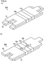
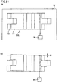
- Figs. 1(a) and 1(b) are perspective views schematically showing one example of the holding sealing material according to the first embodiment.
- Fig. 1(a) is a perspective view of the holding sealing material observed from a first mat side
- Fig. 1(b) is a perspective view of the holding sealing material observed from a second mat side.
- two mats (a first mat 11 and a second mat 12) having an approximately rectangular plane view and a prescribed length in the longitudinal direction (hereinafter, sometimes referred to simply as "whole length”: shown by arrows “L 1 " and “L 2 " in Fig. 1(a) ), width (shown by an arrow “W” in Fig. 1(a) ) and thickness (shown by an arrow “T” in Fig. 1(a) ) are layered.
- the whole length L 1 of the first mat 11 is shorter than the whole length L 2 of the second mat 12.
- the whole length of the mats is the length without taking the sizes of projected portions or recessed portions formed in the end parts of the mats into consideration.
- the whole length of the first mat 11 is the length shown by an arrow "L 1 " and the whole length of the second mat 12 is the length shown by an arrow "L 2 ".
- a projected portion 13a is formed in one end part and a recessed portion 13b is formed in the other end part between the end parts of the first mat 11 in the longitudinal direction.
- a projected portion 14a is formed in one end part and a recessed portion 14b is formed in the other end part between the end parts of the second mat 12 in the longitudinal direction.
- the projected portion 13a and the recessed portion 13b of the first mat 11 as well as the projected portion 14a and the recessed portion 14b of the second mat 12 are so formed as to be fitted with each other when the holding sealing material 10A is wound on an exhaust gas treating body in order to assemble an exhaust gas purifying apparatus as described below.
- the mats composing the holding sealing material are desirable to be needled mats obtained by subjecting base mats including inorganic fibers to needling treatment.
- Needling treatment means inserting and pulling fiber entwining means such as needles in and out base mats.
- inorganic fibers with a relatively long average fiber length are entwined three-dimensionally by needling treatment.
- the first mat 11 and the second mat 12 are subjected to the needling treatment in the width direction perpendicular to the longitudinal direction.
- the inorganic fibers have an average fiber length to a certain extent and for example, the average fiber length of the inorganic fibers is desirably 50 ⁇ m to 100 mm.
- the mats composing the holding sealing material may include a binder such as an organic binder.
- the number of the mats to be layered is not particularly limited and may be three or more.
- a mat with the shortest whole length (sometimes, referred to also as shortest mat) among a plurality of mats is a mat wound on the circumference of an exhaust gas treating body, and next, a mat with whole length longer than that of the shortest mat is layered and thereafter, the whole length of mats becomes longer as the mats are layered more serially.
- the holding sealing material is composed of two mats (the first mat 11 and the second mat 12) such as the holding sealing material 10A shown in Figs. 1 (a) and 1(b)
- one mat (the first mat 11) with shorter whole length than the other is called as the shortest mat.
- the first mat 11 and the second mat 12 are bundled with two belt-shaped bodies (a first belt-shaped body 16a and a second belt-shaped body 17a).
- the first belt-shaped body 16a and the second belt-shaped body 17a respectively have a prescribed width (shown by arrows "X 1 " and “X 2 " in Fig. 1(a) ) in the longitudinal direction of the mats and are wound on the circumference of the layered first mat 11 and second mat 12 in the width direction of the mats.
- the belt-shaped bodies are made of a material having no fixing strength (fixing force). That is, the belt-shaped bodies and the mats are not fixed to each other. Therefore, the mats are not fixed to one another completely and the mats can be shifted in the longitudinal direction.
- the material for the belt-shaped bodies is not particularly limited if it has no fixing strength and examples may include paper, a film, a cloth, and rubber.
- Paper forming the belt-shaped bodies may be common paper produced from plant fibers as a raw material and also paper of which the surface is processed by laminating process or the like.
- the type and the material of paper are not particularly limited.
- a film composing the belt-shaped bodies is desirably an organic film but it may be an inorganic film.
- the organic film is desirably made of an organic material such as a synthetic resin or the like.
- Practical examples of the organic film may include a polyethylene film, a polyolefin film, a poly (vinyl chloride) film, a poly (vinyl alcohol) film, a polypropylene film, a polyester film, a polycarbonate film, a polystyrene film, a polyamide film, and a polyimide film.
- the inorganic film is desirably made of an inorganic material such as a metal, a ceramic or the like.
- Practical examples of the inorganic film may include a metal foil of aluminum, copper, iron, silver, gold, and their mixtures, or a ceramic film of alumina, silica, or the like.
- paper or a film is desirable. Further, among films, an organic film is desirable and a polyethylene film or a polyolefin film is more desirable.
- the film may be a film composed of a plurality of these materials.
- Rubber composing the belt-shaped bodies is desirably synthetic rubber but it may be natural rubber.
- the synthetic rubber may include acrylic rubber, nitrile rubber, styrene-butadiene rubber, butadiene rubber, ethylene-propylene rubber, urethane rubber, or silicone rubber.
- a cloth composing the belt-shaped bodies may include a plant fiber cloth, an inorganic fiber cloth, a glass fiber cloth, a nonwoven cloth, and an artificial fiber cloth.
- At least one end part of the first belt-shaped body 16a in the longitudinal direction is stuck on the belt-shaped body by an adhesive part 18a.
- the other end part of the first belt-shaped body 16a in the longitudinal direction is not stuck on the belt-shaped body.
- one end part of the second belt-shaped body 17a in the longitudinal direction is stuck on the belt-shaped body by an adhesive part 19a.
- the other end part of the second belt-shaped body 17a in the longitudinal direction is not stuck on the belt-shaped body.
- the adhesive part 18a of the first belt-shaped body 16a and the adhesive part 19a of the second belt-shaped body 17a are both positioned in the main face of the first mat 11.
- the longitudinal direction of the belt-shaped bodies means the direction perpendicular to the width direction of the belt-shaped bodies, and the longitudinal direction of the belt-shaped bodies in Figs. 1(a) and 1(b) is coincident with the width direction of the mats.
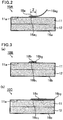
- Fig. 2 is a cross-sectional view schematically showing the adhesive part of the first belt-shaped body in the holding sealing material shown in Figs. 1(a) and 1(b) .
- the first end part 16 a1 of the first belt-shaped body 16a in the longitudinal direction is stuck on the belt-shaped body by an adhesive part 18a.
- the second end part 16 a2 of the first belt-shaped body 16a in the longitudinal direction is not stuck on the belt-shaped body.
- the adhesive part 18a is positioned on the main face 11a of the first mat 11, which is one surface of the holding sealing material 10A.
- the configuration of the adhesive part of the belt-shaped bodies is not particularly limited to the configuration shown in Fig. 2 and examples may include configurations shown below.
- Figs. 3(a) and 3(b) are cross-sectional views schematically showing another example of a holding sealing material according to the first embodiment.
- both ends (the first end part 16 b1 and the second end part 16 b2 ) of the first belt-shaped body 16b in the longitudinal direction are stuck on the belt-shaped body by an adhesive part 18b.
- the adhesive part 18b is positioned on the main face 11a of the first mat 11, which is one surface of the holding sealing material 10B.
- both ends (the first end part 16 c1 and the second end part 16 c2 ) of the first belt-shaped body 16c in the longitudinal direction and a portion between the first end part 16 c1 and the second end part 16 c2 are stuck on the belt-shaped body by an adhesive part 18c.
- the adhesive part 18c is positioned on the main face 11a of the first mat 11, which is one surface of the holding sealing material 10C.
- the first belt-shaped body 16b shown in Fig. 3 (a) and the first belt-shaped body 16c shown in Fig. 3(b) are common in a point that both ends of the belt-shaped bodies are stuck on the belt-shaped bodies, but the size of the adhesive part differs.
- the first end parts of the belt-shaped bodies in the longitudinal direction are all positioned closer to the first mat 11 side than the second end parts of the belt-shaped bodies in the longitudinal direction.
- the second end part of the belt-shaped body in the longitudinal direction may be positioned closer to the first mat 11 side than the first end part of the belt-shaped body in the longitudinal direction.
- the first end part of the first belt-shaped body in the longitudinal direction is stuck on the belt-shaped body by an adhesive part, and the second end part of the first belt-shaped body in the longitudinal direction is not stuck on the belt-shaped body; however, in the holding sealing material according to the first embodiment, the second end part of the first belt-shaped body in the longitudinal direction may be stuck on the belt-shaped body by an adhesive part, and the first end part of the first belt-shaped body in the longitudinal direction may not be stuck on the belt-shaped body.
- the adhesive part of the first belt-shaped body may be positioned at any position without any limit if it is positioned on the main face of the first mat, that is, one surface of the holding sealing material.
- the adhesive part 18a of the first belt-shaped body 16a and the adhesive part 19a of the second belt-shaped body 17a have the same configuration and are positioned at the same position.
- the configurations of the adhesive parts may be different from each other. Further, although the adhesive parts have the same configuration, the positions of the adhesive parts may be different from each other.
- a method for providing the adhesive parts on the belt-shaped bodies is not particularly limited and any method can be employed for forming the adhesive parts by sticking the end parts of the belt-shaped bodies to the belt-shaped bodies.
- a method for sticking the belt-shaped bodies may properly be determined corresponding to materials of the belt-shaped bodies, and examples may include a method for sticking by using an adhesive such as glue or an adhesive tape; a method for sticking by using hot melt, ultrasonic, or the like; and a method for sticking by using the heat adhesion of the belt-shaped bodies themselves.
- the number of the belt-shaped bodies is not particularly limited to be two but may be three or more.
- each belt-shaped body may have an adhesive part and the adhesive part may be positioned at the main face of the first mat. Further, the configurations and positions of the adhesive parts may be same or different, respectively.
- the width of one belt-shaped body (the length shown by arrows "X 1 " and “X 2 " in Fig. 1(a) ) is desirably 10 to 100 mm, more desirably 20 to 80 mm, and even more desirably 30 to 50 mm.
- the width of one belt-shaped body is narrower than 10 mm, the belt-shaped body tends to be torn easily.
- the width of one belt-shaped body exceeds 100 mm, in the case the number of the belt-shaped bodies is high, the surface area of the belt-shaped bodies to the surface area of the holding sealing material is so wide that the holding force of the holding sealing material could be lowered.
- the holding sealing material is used for an exhaust gas purifying apparatus. It is supposed that the heated and decomposed organic components having fluidity then lower the friction between the mats (holding sealing material) and the casing composing an exhaust gas purifying apparatus or the friction between the mats (holding sealing material) and an exhaust gas treating body and therefore, the holding force of the holding sealing material is lowered.
- the distance between the end (first width end portion) of a belt-shaped body nearest to the first end faces (first longitudinal end face) of the mats in the longitudinal direction and the end (second width end portion) of a belt-shaped body nearest to the second end faces (second longitudinal end face) of the mats in the longitudinal direction is desirably 30% or less of the length of the shortest mat in the longitudinal direction and more desirably 4 to 20%.
- the surface area of the belt-shaped bodies to the surface area of the holding sealing material (mats) is so wide that the holding force of the holding sealing material could be lowered.
- a material composing the belt-shaped bodies is an organic substance such as paper or a film
- the surface area of the belt-shaped bodies becomes wide, the organic components of the belt-shaped bodies to be heated and decomposed by the heat of the exhaust gas could supposedly be increased when the holding sealing material is used for an exhaust gas purifying apparatus.
- the end of a belt-shaped body nearest to the first end faces of the mats in the longitudinal direction and the end of a belt-shaped body nearest to the second end faces of the mats in the longitudinal direction are desirably positioned at positions of 5 to 45% of the whole length of the shortest mat toward the respective end faces of the mats from the bisectioning position of the mats in the longitudinal direction, more desirably 8 to 30%, and even more desirably 10 to 15%.
- the belt-shaped bodies are so close to the center of the mats in the longitudinal direction that the effect of preventing the positional deviation of the mats in the width direction could not be obtained sufficiently.
- the belt-shaped bodies are so close to the end faces of the mats in the longitudinal direction that the belt-shaped bodies tends to come off the mats.
- the thickness of the belt-shaped bodies is desirably 0.008 to 1.5 mm.
- the belt-shaped bodies tend to be torn easily and it becomes difficult to bundle mats.
- the belt-shaped bodies if the thickness of the belt-shaped bodies exceeds 1.5 mm, the belt-shaped bodies become an obstacle or easy to be hooked on other points in the step of winding the holding sealing material when manufacturing an exhaust gas purifying apparatus. As a result, the production efficiency of the exhaust gas purifying apparatus tends to be lowered.
- the length of the adhesive part of a belt-shaped body in the width direction of the mats is not particularly limited and desirably 3% or more of the width of the mats and more desirably 5 to 15%.
- the adhesive part of a belt-shaped body in the width direction of the mats is less than 3% of the width of the mats, the adhesive part is so small that the end parts of the belt-shaped body tend to be peeled.
- the length from the second end part to the adhesive part of the belt-shaped body in the longitudinal direction is desirably 30% or less of the width of the mats and more desirably 5 to 20%.
- the belt-shaped body becomes an obstacle or easy to be hooked on other points in the step of winding the holding sealing material when manufacturing an exhaust gas purifying apparatus. As a result, the production efficiency of the exhaust gas purifying apparatus tends to be lowered.
- the adhesive part of a belt-shaped body is desirably formed evenly in the longitudinal direction and in the width direction of the mats. That is, the adhesive part of a belt-shaped body is desirably formed in an approximately rectangular form in a plane view. It is because the end part of a belt-shaped body can firmly be stuck.
- the plane view shape of the adhesive part of a belt-shaped body is not particularly limited and may be an arbitrary form such as an approximately circular, approximately elliptical, and approximately polygonal forms. Further, the adhesive part of a belt-shaped body may partially have a portion which is not stuck just like a doughnut-like form in a plane view.
- a base mat produced by entwining inorganic fibers by a spinning method is punched to prepare base mats with different length.
- the base mats with different length are subjected to needling treatment, if necessary, to produce a plurality of mats needed for manufacturing a holding sealing material.
- the inorganic fibers are loosely entwined through the spinning process. Execution of the needling treatment for the loosely entwined inorganic fibers entwines the inorganic fibers more complicatedly and thus gives mats having an entwined structure enough to keep the shape to a certain extent without a binder.
- the whole length of the shortest mat to be wound on an exhaust gas treating body corresponds to the circumferential length of the exhaust gas treating body and thus the whole length of the shortest mat is determined based on the circumferential length of the exhaust gas treating body.
- the whole length of a mat which is to be put on the outside of the shortest mat corresponds to the circumferential length of the diameter calculated by adding the thickness of the shortest mat in the case of winding the mat to the diameter of the exhaust gas treating body and thus the whole length of the mat to be put on the outside of the shortest mat is determined by measuring the circumferential length.
- the procedure is serially repeated to determine each whole length of a plurality of mats to be layered.
- a binder is provided on the mats subjected to the needling treatment. Provision of the binder to the mats makes the entwined structure of the inorganic fibers firmer and suppresses the bulkiness of the mats.
- an emulsion prepared by dispersing acrylic latex, rubber type latex, or the like in water can be used as the binder.
- the binder is evenly sprayed to the entire body of a mat by using a spray or the like to provide the binder to the mat.
- the drying condition may be, for example, at 95 to 150°C for 1 to 30 minutes. Mats can be produced through the drying step.
- a plurality of mats with different length are produced and the mats are layered in the order of the length becoming longer or shorter.
- the number of mats to be layered may be changed in accordance with the holding force or heat insulating capacity which the holding sealing material is required to have.
- a representative layering procedure is at first layering a mat with the longest length and serially layering mats with shorter whole length as the number of layers is increased more.
- a mat with a shorter whole length to be layered may be layered on a mat with a longer whole length while adjusting its position in a manner of preventing both ends of the shorter mat from coming out the longer mat or in a manner that the shorter mat comes out one end of the longer mat by mutually shifting the mats in the longitudinal direction.
- a plurality of layered mats are bundled by a belt-shaped body.
- a method to be employed may be a method involving preparing a long tape having a constant width and made of paper and repeating steps of winding the tape around the circumference of a plurality of mats, thereafter cutting the tape, and sticking at least one end part of the tape on the tape a number of times same as the number of the belt-shaped bodies.
- Amethod of sticking the tape may be, as described above, a method for sticking by using an adhesive such as glue or an adhesive tape; a method for sticking by using hot melt, ultrasonic, or the like; and a method for sticking by using the heat adhesion of the belt-shaped bodies themselves.
- the holding sealing material according to the first embodiment can be produced according to the above-mentioned method.
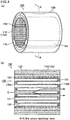
- Fig. 4(a) is a perspective view schematically showing one example of an exhaust gas purifying apparatus according to the first embodiment
- Fig. 4(b) is a A-A line cross-sectional view of the exhaust gas purifying apparatus shown in Fig. 4(a) .
- the exhaust gas purifying apparatus 100 is composed of a pillar-shaped exhaust gas treating body 130 having a large number of cells 131 longitudinally disposed in parallel with one another with cell walls 132 therebetween, a casing 120 for housing the exhaust gas treating body 130, and a holding sealing material 110 which is provided between the exhaust gas treating body 130 and the casing 120 and which holds the exhaust gas treating body 130.
- an introduction pipe for introducing exhaust gas emitted out of an internal combustion engine and a discharge pipe for discharging the exhaust gas passed through the exhaust gas purifying apparatus outside may be connected to the end parts of the casing 120.
- a honeycomb filter in which either one end of the respective cells are sealed with a plug material 133 is used as the exhaust gas treating body 130, as shown in Fig. 4(b) .
- the holding sealing material 10A shown in Fig. 1(a), Fig. 1(b) and Fig. 2 is used as the holding sealing material 110.
- an arbitrary holding sealing material according to the first embodiment may be used as the holding sealing material.
- the exhaust gas discharged out of an internal combustion engine and flowing in the exhaust gas purifying apparatus 100 (exhaust gas is shown as "G" and the flow of the exhaust gas is shown by an arrow in Fig. 4(b) ) flows in one cells 131 opened in the end face 130a in the exhaust gas flow-in side of the exhaust gas treating body (honeycomb filter) 130 and passes through the cell walls 132 partitioning the cells 131. At that time, PM in the exhaust gas is collected by the cell walls 132 to purify the exhaust gas. The purified exhaust gas flows out of the other cells 131 opened in the end face 130b in the exhaust gas flow-out side and is discharged outside.
- the configuration of the holding sealing material 110 is already explained as the holding sealing material according to the first embodiment and therefore the explanation will be omitted.
- Pig. 5 is a perspective view schematically showing one example of the exhaust gas treating body composing the exhaust gas purifying apparatus according to the first embodiment of the present invention.
- the exhaust gas treating body (honeycomb filter) 130 is made of mainly a porous ceramic and its shape is approximately round pillar-shaped.
- a periphery coating layer 134 is formed on the periphery of the honeycomb filter 130, aiming to reinforce the periphery of the honeycomb filter 130, adjust the form, and improve the heat insulation property of the honeycomb filter 130.
- the configuration of the inside of the honeycomb filter 130 is the same as already described above in the explanation of the exhaust gas purifying apparatus according to the first embodiment (see Fig. 4(b) ).
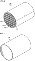
- Fig. 6 is a perspective view schematically showing one example of the casing composing the exhaust gas purifying apparatus according to the first embodiment.
- the casing 120 shown in Fig. 6 is made of mainly a metal such as a stainless steel and its shape is approximately cylindrical.
- the inner diameter of the casing is made slightly shorter than the total length of the diameter of the end faces of the honeycomb filter 130 and the thickness of the holding sealing material 10A in the state of being wound on the honeycomb filter 130, and the length of the casing is almost the same as the length of the honeycomb filter 130 in the longitudinal direction (the direction shown by an arrow "a" in Fig. 5 ).
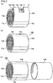
- Figs. 7(a), 7(b), and 7(c) are perspective views schematically showing one example of a method for manufacturing the exhaust gas purifying apparatus according to the first embodiment.
- a method for manufacturing the exhaust gas purifying apparatus 100 shown in Figs. 4 (a) and 4 (b) will be described as one example of a method for manufacturing an exhaust gas purifying apparatus according to the first embodiment.
- the holding sealing material 10A shown in Fig. 1(a), Fig. 1(b) and Fig. 2 is wound on the circumference of the exhaust gas treating body (honeycomb filter) 130 to produce a wound body (the exhaust gas treating body wound with the holding sealing material) 150 (winding step).
- the holding sealing material 10A produced in the above-mentioned processes is wound on the outer circumference of an approximately round pillar-shaped exhaust gas treating body 130 produced by a conventionally known method in a manner that the projected portions 13a and the recessed portions 13b are fitted and the projected portions 14a and the recessed portions 14b are fitted.
- the holding sealing material 10A is wound on the circumference of the exhaust gas treating body 130 in a manner that the main face of the mat on which the adhesion part 18a of the first belt-shaped body 16a and the adhesion part 19a of the second belt-shaped body 17a of the holding sealing material 10A are positioned; that is, the main face of the first mat 11; is brought into contact with the exhaust gas treating body 130 (the adhesion part 18a of the first belt-shaped body 16a and the adhesion part 19a of the second belt-shaped body 17a are not illustrated in Fig. 7(a) ).
- the wound body 150 shown in Fig. 7(b) can be produced.
- the produced wound body 150 is housed in the casing 120 made of mainly a metal and having an approximately cylindrical form with a prescribed size (housing step).
- the inner diameter of the casing 120 is made to be slightly smaller than the outermost diameter including the thickness of the holding sealing material 10A of the exhaust gas treating body 130 wound with the holding sealing material 10A.
- the exhaust gas purifying apparatus 100 shown in Figs. 4 (a) and 4 (b) can be manufactured by the above-mentioned method.
- examples of a method for housing the wound body in the casing may include a stuffing method, a sizing method (a swaging method), and a clamshell method.
- the stuffing method is for stuffing the wound body to a prescribed position in the inside of the casing by using a stuffing tool or the like.
- the sizing method (a swaging method) is for inserting the wound body in the casing and thereafter compacting the casing from the outer circumference side so as to narrow the inner diameter of the casing.
- the clamshell method is for making the casing have a form separable into two parts, a first casing and a second casing, setting the wound body on the first casing, and then putting the second casing on and sealing them.
- the stuffing method or the sizing method (the swaging method) is desirable. It is because it is unnecessary for the stuffing method and the sizing method (the swaging method) to use two parts as the casing and the number of manufacturing processes can be lessened.
- the belt-shaped body becomes unnecessary. Therefore, the belt-shaped body can be removed by using a cutting tool such as a pair of scissors, a cutter, or the like.
- the amount of the organic components of the belt-shaped bodies to be heated and decomposed by the heat of the exhaust gas can be decreased at the time of using the exhaust gas purifying apparatus by removing the belt-shaped body.
- the belt-shaped body may remain or may not remain in the exhaust gas purifying apparatus after manufacture.
- the holding sealing material according to the second embodiment is obtained by layering a plurality of mats including inorganic fibers and bundling the plurality of mats with two or more belt-shaped bodies having no fixing force. At least one end part of the belt-shaped bodies composing the holding sealing material in the longitudinal direction is stuck on the belt-shaped bodies by an adhesive part.
- the adhesive part of the belt-shaped bodies is positioned on the main face of the mat opposed to the side to be brought into contact with the exhaust gas treating body in the case an exhaust gas purifying apparatus is manufactured using the holding sealing material.
- Figs. 8(a) and 8(b) are perspective views schematically showing one example of the holding sealing material according to the second embodiment.
- Fig. 8 (a) is a perspective view of the holding sealing material observed from a first mat side
- Fig. 8(b) is a perspective view of the holding sealing material observed from a second mat side.
- the first mat 21 and the second mat 22 are bundled with two belt-shaped bodies (a first belt-shaped body 26a and a second belt-shaped body 27a).
- one end part of the first belt-shaped body 26a in the longitudinal direction is stuck on the belt-shaped body by an adhesive part 28a.
- the other end part of the first belt-shaped body 26a in the longitudinal direction is not stuck on the belt-shaped body.
- one end part of the second belt-shaped body 27a in the longitudinal direction is stuck on the belt-shaped body by an adhesive part 29a.
- the other end part of the second belt-shaped body 27a in the longitudinal direction is not stuck on the belt-shaped body.
- the adhesive part 28a of the first belt-shaped body 26a and the adhesive part 29a of the second belt-shaped body 27a are both positioned on the main face of the second mat 22.
- the configurations of the adhesive parts of the belt-shaped bodies may be similar to the configurations represented by those shown in Fig. 2 and Figs. 3(a) and 3(b) and described for the holding sealing material according to the first embodiment.
- the length from the one end part to the adhesive part of the belt-shaped body in the longitudinal direction is desirably 5 to 20% of the width of the mats.
- the belt-shaped body in the case one end part of the belt-shaped body in the longitudinal direction is not stuck on the belt-shaped body, the belt-shaped body can easily be peeled after the holding sealing material is wound on the circumference of the exhaust gas treating body.
- the belt-shaped body becomes difficult to be peeled after the holding sealing material is wound on the circumference of the exhaust gas treating body.
- the belt-shaped body becomes an obstacle or easy to be hooked on other points in the step of winding the holding sealing material when manufacturing an exhaust gas purifying apparatus. As a result, the production efficiency of the exhaust gas purifying apparatus tends to be lowered.
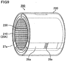
- Fig. 9 is a perspective view schematically showing one example of the exhaust gas purifying apparatus according to the second embodiment.
- the exhaust gas purifying apparatus 200 is composed of an exhaust gas treating body (honeycomb filter) 230, a casing 220 for housing the exhaust gas treating body 230, and a holding sealing material 210 which is provided between the exhaust gas treating body 230 and the casing 220 and which holds the exhaust gas treating body 230.
- an exhaust gas treating body honeycomb filter
- a casing 220 for housing the exhaust gas treating body 230 for housing the exhaust gas treating body 230
- a holding sealing material 210 which is provided between the exhaust gas treating body 230 and the casing 220 and which holds the exhaust gas treating body 230.
- the holding sealing material 20A shown in Figs. 8 (a) and 8 (b) is used as the holding sealing material 210.
- an arbitrary holding sealing material according to the second embodiment can be used as the holding sealing material.
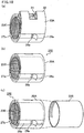
- Figs. 10(a), 10(b), and 10(c) are perspective views schematically showing one example of a method for manufacturing the exhaust gas purifying apparatus according to the second embodiment
- a method for manufacturing the exhaust gas purifying apparatus 200 shown in Fig. 9 will be described as one example of the method for manufacturing an exhaust gas purifying apparatus according to the second embodiment.
- the holding sealing material 20A shown in Figs. 8(a) and 8(b) is wound on the circumference of the exhaust gas treating body (honeycomb filter) 230 to produce a wound body (the exhaust gas treating body wound with the holding sealing material) 250 (winding step).
- the holding sealing material 20A is wound on the circumference of the exhaust gas treating body 230 in a manner that the main face of the mat in the opposed side in which the adhesion part 28a of the first belt-shaped body 26a and the adhesion part 29a of the second belt-shaped body 27a of the holding sealing material 20A are positioned; that is, the main face of the first mat 21; is brought into contact with the exhaust gas treating body 230 (the adhesion part 29a of the second belt-shaped body 27a is not illustrated in Fig. 10(a) ).
- the wound body 250 shown in Fig. 10(b) can be produced.
- the produced wound body 250 is housed in the casing 220 made of mainly a metal and having an approximately cylindrical form with a prescribed size (housing step).
- the exhaust gas purifying apparatus 200 shown in Fig. 9 can be manufactured by the above-mentioned method.
- the belt-shaped body may be removed by using a cutting tool such as a pair of scissors, a cutter, or the like.
- the belt-shaped body may remain or may not remain in the exhaust gas purifying apparatus after manufacture.
- the method for manufacturing an exhaust gas purifying apparatus according to the second embodiment is similar to the method for manufacturing an exhaust gas purifying apparatus according to the first embodiment except the above-mentioned point and therefore, its detailed explanation will be omitted.
- the second embodiment the effects (1) to (7) described in the first embodiment and also the following effect.
- At least one end of a belt-shaped body in the longitudinal direction composing the holding sealing material is stuck on the belt-shaped body by an adhesive part, and the adhesive part of the belt-shaped body is positioned on the main face of the mat in the side opposed to the side to be brought into contact with the exhaust gas treating body.
- the belt-shaped body When the adhesive part of the belt-shaped body is positioned on the main face of a mat in the opposed side to the side to be brought into contact with the exhaust gas treating body, the belt-shaped body can easily be removed by peeling the adhesive part with no need of using a tool such as a pair of scissors.
- the holding sealing material according to the third embodiment is obtained by layering a plurality of mats including inorganic fibers and bundling the plurality of mats with two or more belt-shaped bodies having no fixing force. At least one end part of the belt-shaped bodies composing the holding sealing material in the longitudinal direction is stuck on the belt-shaped bodies by an adhesive part.
- the adhesive part of the belt-shaped bodies is positioned on the first end face (first width end face) or the second end face (second width end face) of at least one of the mats in the width direction.
- Fig. 11 is a perspective view schematically showing one example of the holding sealing material according to the third embodiment
- the first mat 31 and the second mat 32 are bundled with two belt-shaped bodies (a first belt-shaped body 36a and a second belt-shaped body 37a).
- one end part of the first belt-shaped body 36a in the longitudinal direction is stuck on the belt-shaped body by an adhesive part 38a.
- the other end part of the first belt-shaped body 36a in the longitudinal direction is not stuck on the belt-shaped body.
- one end part of the second belt-shaped body 37a in the longitudinal direction is stuck on the belt-shaped body by an adhesive part 39a.
- the other end part of the second belt-shaped body 37a in the longitudinal direction is not stuck on the belt-shaped body.
- the adhesive part 38a of the first belt-shaped body 36a and the adhesive part 39a of the second belt-shaped body 37a are both positioned on the first end face of the mat in the width direction.
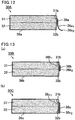
- Fig. 12 is a cross-sectional view schematically showing an adhesive part of the first belt-shaped body in the holding sealing material shown in Fig. 11 .
- a first end part 36 a1 of the first belt-shaped body 36a in the longitudinal direction is stuck on the belt-shaped body by an adhesive part 38a.
- the second end part 36 a2 of the first belt-shaped body 36a in the longitudinal direction is not stuck on the belt-shaped body.
- the adhesive part 38a is positioned on the first end faces of the mats in the width direction; that is, one side face of the holding sealing material 30A (the first end face 31b of the first mat 31 in the width direction and the first end face 32b of the second mat 32 in the width direction).
- the configuration of the adhesive part of the belt-shaped bodies is not particularly limited to the configuration shown in Fig. 12 and examples may include configurations shown below.
- Figs. 13(a) and 13(b) are cross-sectional views schematically showing another example of a holding sealing material according to the third embodiment
- both ends (the first end part 36 b1 and the second end part 36 b2 ) of the first belt-shaped body 36b in the longitudinal direction are stuck on the belt-shaped body by an adhesive part 38b.
- the adhesive part 38b is positioned on the first end faces of the mats in the width direction; that is, one side face of the holding sealing material 30B (the first end face 31b of the first mat 31 in the width direction and the first end face 32b of the second mat 32 in the width direction).
- both ends (the first end part 36 c1 and the second end part 36 c2 ) of the first belt-shaped body 36c in the longitudinal direction and a portion between the first end part 36 c1 and the second end part 36 c2 are stuck on the belt-shaped body by an adhesive part 38c.
- the adhesive part 38c is positioned on the first end faces of the mats in the width direction; that is, one side face of the holding sealing material 30C (the first end face 31b of the first mat 31 in the width direction and the first end face 32b of the second mat 32 in the width direction).
- the first belt-shaped body 36b shown in Fig. 13 (a) and the first belt-shaped body 36c shown in Fig. 13 (b) are common in a point that both ends of the belt-shaped bodies are stuck on the belt-shaped bodies, but the size of the adhesive part differs.
- the first end parts of the belt-shaped bodies in the longitudinal direction are all positioned closer to the first mat 31 side and the second mat 32 side than the second end parts of the belt-shaped bodies in the longitudinal direction.
- the second end part of the belt-shaped body in the longitudinal direction may be positioned closer to the first mat 31 side and the second mat 32 side than the first end part of the belt-shaped body in the longitudinal direction.
- the first end part of the first belt-shaped body in the longitudinal direction is stuck on the belt-shaped body by an adhesive part, and the second end part of the first belt-shaped body in the longitudinal direction is not stuck on the belt-shaped body; however, in the holding sealing material according to the third embodiment , the second end part of the first belt-shaped body in the longitudinal direction may be stuck on the belt-shaped body by an adhesive part, and the first end part of the first belt-shaped body in the longitudinal direction may not be stuck on the belt-shaped body.
- the adhesive part of the first belt-shaped body may be positioned not on the first end face of the mat in the width direction; that is, one side face of the holding sealing material but on the second end face opposed to the first end face of the mat in the width direction.
- the adhesive part of the first belt-shaped body may be positioned at any position without any particular limit if it is positioned on the first end face or the second end face of the mat in the width direction.
- the adhesive part 38a of the first belt-shaped body 36a and the adhesive part 39a of the second belt-shaped body 37a have the same configuration and are positioned at the same position.
- the configurations of the adhesive parts may be different from each other.
- the adhesive parts have the same configuration, the positions of the adhesive parts may be different from each other.
- a belt-shaped body having the adhesive part positioned on the first end face of the mat in the width direction and a belt-shaped body having the adhesive part positioned on the second end face of the mat in the width direction may coexist.
- the length from the one end part to the adhesive part of the belt-shaped body in the longitudinal direction is desirably 5 to 10% of the width of the mats.
- the belt-shaped body in the case one end part of the belt-shaped body in the longitudinal direction is not stuck on the belt-shaped body, the belt-shaped body can easily be peeled after the holding sealing material is wound on the circumference of the exhaust gas treating body.
- the belt-shaped body becomes difficult to be peeled after the holding sealing material is wound on the circumference of the exhaust gas treating body.
- the belt-shaped body becomes an obstacle or easy to be hooked on other points in the step of winding the holding sealing material when manufacturing an exhaust gas purifying apparatus. As a result, the production efficiency of the exhaust gas purifying apparatus tends to be lowered.
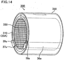
- Fig. 14 is a perspective view schematically showing one example of the exhaust gas purifying apparatus according to a third embodiment
- the exhaust gas purifying apparatus 300 is composed of an exhaust gas treating body (honeycomb filter) 330, a casing 320 for housing the exhaust gas treating body 330, and a holding sealing material 310 which is provided between the exhaust gas treating body 330 and the casing 320 and which holds the exhaust gas treating body 330.
- the holding sealing material 30A shown in Fig. 11 and Fig. 12 is used as the holding sealing material 310.
- an arbitrary holding sealing material according to the third embodiment of the present invention can be used as the holding sealing material.
- Figs. 15(a), 15(b), and 15(c) are perspective views schematically showing one example of a method for manufacturing the exhaust gas purifying apparatus according to the third embodiment
- the holding sealing material 30A shown in Fig. 11 and Fig. 12 is wound on the circumference of the exhaust gas treating body (honeycomb filter) 330 to produce a wound body (the exhaust gas treating body wound with the holding sealing material) 350 (winding step).
- the holding sealing material 30A is wound on the circumference of the exhaust gas treating body 330 in a manner that the main face of the first mat 31 of the holding sealing material 30A is brought into contact with the exhaust gas treating body 330.
- the wound body 350 shown in Fig. 15(b) can be produced.
- the produced wound body 350 is housed in the casing 320 made of mainly a metal and having an approximately cylindrical form with a prescribed size (housing step).
- the exhaust gas purifying apparatus 300 shown in Fig. 14 can be manufactured by the above-mentioned method.
- the adhesive part of the belt-shaped body is positioned on the first end face or the second end face of the mat in the width direction. Therefore, the belt-shaped body can easily be removed by peeling the adhesive part. Further, if one end part of the belt-shaped body in the longitudinal direction is not stuck on the belt-shaped body, the belt-shaped body can easily be removed from the end part which is not stuck.
- the belt-shaped body may be removed by using a cutting tool such as a pair of scissors, a cutter, or the like.
- the belt-shaped body may remain or may not remain in the exhaust gas purifying apparatus after manufacture.
- the method for manufacturing an exhaust gas purifying apparatus according to the third embodiment is similar to the method for manufacturing an exhaust gas purifying apparatus according to the first embodiment , except the above-mentioned point and therefore, its detailed explanation will be omitted.
- the third embodiment can cause the effects (1) to (7) described in the first embodiment and also the following effect.
- (10) With respect to the method for manufacturing an exhaust gas purifying apparatus of the present embodiment, at least one end part of the belt-shaped body composing the holding sealing material in the longitudinal direction is stuck on the belt-shaped body by an adhesive part, and the adhesive part of the belt-shaped body is positioned on the first end face or the second end face of at least one of the mats in the width direction side. Therefore, the belt-shaped body can easily be removed by peeling the adhesive part.
- the holding sealing material according to the fourth embodiment is obtained by layering a plurality of mats including inorganic fibers and bundling the plurality of mats with one belt-shaped body having no fixing force.
- the holding sealing material according to the fourth embodiment has the similar configuration to that of the holding sealing material according to any of the first to the third embodiments , except the above-mentioned point.
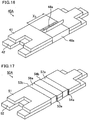
- Fig. 16 is a perspective view schematically showing one example of the holding sealing material according to the fourth embodiment
- the first mat 41 and the second mat 42 are bundled with one belt-shaped body 46a.
- one end part of the belt-shaped body 46a in the longitudinal direction is stuck on the belt-shaped body by an adhesive part 48a.
- the other end part of the belt-shaped body 46a in the longitudinal direction is not stuck on the belt-shaped body.
- the adhesive part 48a of the belt-shaped body 46a is positioned on the main face of the first mat 41.
- the distance between the end of a belt-shaped body nearest to the first end faces of the mats in the longitudinal direction and the end of a belt-shaped body nearest to the second end faces of the mats in the longitudinal direction are coincident with the width of one belt-shaped body (the length shown by an arrow "X 3 " in Fig. 16 ).
- the width of one belt-shaped body is desirably 10 to 100 mm, more desirably 20 to 80 mm, and even more desirably 30 to 50 mm.
- the width of one belt-shaped body is narrower than 10 mm, the width for fixing a plurality of mats is too narrow to cause a sufficient effect of preventing the positional deviation of the mats in the width direction.
- the width of one belt-shaped body exceeds 100 mm, the surface area of the belt-shaped body to the surface area of the holding sealing material is so wide that the holding force of the holding sealing material could be lowered.
- the holding sealing material according to the fourth embodiment is different from the holding sealing materials according to the first to the third embodiments in a point that the number of the belt-shaped body is one.
- the exhaust gas purifying apparatus according to the fourth embodiment has the similar configuration to that of the exhaust gas purifying apparatuses according to any of the first to the third embodiments , except that the holding sealing material according to the fourth embodiment is used. Therefore, the explanation of them will be omitted.
- the fourth embodiment can cause the effects (1) to (4) and (6) to (10) described in the first to the third embodiments
- groove parts so formed as to fix the belt-shaped body are formed in first end faces and second end faces of the mats in the width direction.
- the holding sealing material according to the fifth embodiment of the present invention has the similar configuration to that of the holding sealing material according to any of the first to the fourth embodiments of the present invention, except the above-mentioned point.
- Fig. 17 is a perspective view schematically showing one example of the holding sealing material according to the fifth embodiment of the present invention.
- the first mat 51 and the second mat 52 are bundled with two belt-shaped bodies (a first belt-shaped body 56a and a second belt-shaped body 57a).
- a groove part 53a is so formed as to fix (engage) the first belt-shaped body 56a and a groove part 54a is so formed as to fix (engage) the second belt-shaped body 57a in the first end faces of the mats in the width direction.
- a groove part 53b is so formed as to fix (engage) the first belt-shaped body 56a and a groove part 54b is so formed as to fix (engage) the second belt-shaped body 57a in the second end faces of the mats in the width direction.
- the width (the length in the longitudinal direction of the mats) of the groove parts so formed as to fix the belt-shaped body may be the same as the width of the belt-shaped body and is desirably longer than the width of the belt-shaped body. In this case, since there is a gap between the belt-shaped body and the groove part, the mats can be shifted in the longitudinal direction of the mats.
- the width of the groove parts so formed as to fix the belt-shaped body is preferably 101 to 110% of the width of the belt-shaped body.
- the width of the groove parts is less than 101% of the belt-shaped body, the gap between the belt-shaped body and the groove part is so narrow that the mats are hardly shifted in the longitudinal direction. As a result, the end faces of the mats tend to be deviated in the case the holding sealing material is wound on the circumference of an exhaust gas treating body. On the other hand, if the width of the groove parts exceeds 110% of the belt-shaped body, the effective area of the mats is decreased and therefore, the holding force of the holding sealing material is deteriorated.
- the depth (the length in the width direction of the mats) of the groove parts so formed as to fix the belt-shaped body is desirably 0.1 to 5 mm and more desirably 0.2 to 2 mm.
- the depth of the groove parts is less than 0.1 mm, the effect of forming the groove parts cannot be caused efficiently. On the other hand, if the depth of the groove parts exceeds 5 mm, the belt-shaped body bits the mats too much and therefore, the mats are hardly shifted in the longitudinal direction.
- the holding sealing material according to the fifth embodiment of the present invention is different from the holding sealing materials according to the first to the fourth embodiments in a point that the groove parts are so forme as to fix the belt-shaped body.
- a mat punched into a prescribed form in which the groove parts are formed may be used, or the groove parts may be formed by grinding the end faces of the mats to be used for any of the holding sealing material according to the first to the fourth embodiments of the present invention.
- the exhaust gas purifying apparatus according to the fifth embodiment has the similar configuration to that of the exhaust gas purifying apparatus according to any of the first to the fourth embodiments except that the holding sealing material according to the fifth embodiment of the present invention is used. Therefore, the explanation of them will be omitted.
- the fifth embodiment of the present invention can cause the effects (1) to (10) described in the first to the third embodiments of the present invention and also the following effect.
- groove parts are so formed as to fix the belt-shaped body in first end faces and second end faces of the mats in the width direction.
- the position of the belt-shaped body can be fixed by the groove parts and positional deviation of the mats in the width direction can be further prevented.
- At least one of printing and coloring for displaying identification data of the mats is done on the belt-shaped body.
- the holding sealing material according to the sixth embodiment has the similar configuration to that of the holding sealing material according to any of the first to the fifth embodiments , except the above-mentioned point.
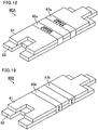
- Fig. 18 is a perspective view schematically showing one example of the holding sealing material according to the sixth embodiment
- the first mat 61 and the second mat 62 are bundled with two belt-shaped bodies (a first belt-shaped body 66a and a second belt-shaped body 67a).
- the holding sealing material 60A shown in Fig. 18 printing is done on the first belt-shaped body 66a and the second belt-shaped body 67a for showing the identification data of the mats. That is, the holding sealing material 60A is provided with data by letters.
- the data by letters may be data relevant to the number of lots, the name of products, production date, etc. and the types of the data are not particularly limited.
- the data of the front and rear face of the holding sealing material may also be expressed by letters.
- the color of the printing is not particularly limited and may include red, blue, yellow, green, and black colors.
- the color of the printing may be all the same or different depending on the data.
- printing is done on a portion of the belt-shaped body positioned on the main face of the first mat 61 for displaying the identification data of the mats.
- the position where printing is done is not particularly limited if the printing of identification data of the mats is done on the belt-shaped body.
- Fig. 19 is a perspective view schematically showing another example of the holding sealing material according to the sixth embodiment
- printing is done on a portion of the belt-shaped body positioned on the first end face of a mat for displaying the identification data of the mats.
- the identification data of mats to be printed on the belt-shaped body is not limited to the data by letters and may be data by one dimensional codes and data by two dimensional codes.
- Examples of the one dimensional codes may be bar codes.
- Examples of the two dimensional codes may be QR codes.
- the data by two dimensional codes may be data of such as the number of lots, the name of products, production history, raw materials, etc. and the types of the data are not particularly limited.
- the data by letters and at least one of one dimensional codes and two dimensional codes may coexist.
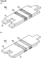
- Figs. 20 (a) and 20 (b) are perspective views schematically showing still another example of a holding sealing material according to the sixth embodiment .
- Fig. 20(a) is a perspective view of the holding sealing material observed from a first mat side
- Fig. 20 (b) is a perspective view of the holding sealing material observed from a second mat side.
- coloring is done on the first belt-shaped body 66c and the second belt-shaped body 67c for displaying the identification data of mats. Practically, the color in the first mat 61 side and the color in the second mat 62 side are different in the first belt-shaped body 66c and the second belt-shaped body 67c.
- the coloring can be said to be identification data showing the front and rear of the holding sealing material.
- the colors are not particularly limited and may include red, blue, yellow, green, and black colors and color combinations easy for the distinction may be selected among these colors.
- red color for the first mat may be possible.
- black color for the second mat may be possible.
- the color of the belt-shaped bodies is desirably different from the color of the mats.
- coloring is done on belt-shaped bodies, it is no need to carry out coloring on the entire face of the belt-shaped bodies but coloring may be carried out only on a portion of the belt-shaped bodies.
- the position where coloring is done is not particularly limited if the coloring for identification data of the mats is done on the belt-shaped bodies.
- both printing and coloring may be done on one belt-shaped body.
- a belt-shaped body on which only printing is done a belt-shaped body on which only coloring is done, and a belt-shaped body on which both printing and coloring are done may be combined arbitrarily.
- the position of a belt-shaped body where printing and/or coloring is done is not particularly limited but it is desirable that printing and/or coloring is done on the portion of the belt-shaped body positioned on at least one of the first end faces and the second end faces of the mats in the width direction. If the identification data of the mats is displayed on the above-mentioned position of the belt-shaped body, the identification data of the mats can be confirmed by seeing the belt-shaped body even after the holding sealing material is wound on the circumference of the exhaust gas treating body.
- the printing and/or coloring on the belt-shaped body is desirably done with an organic pigment or an inorganic pigment and more desirably with an inorganic pigment.
- the identification data on the belt-shaped body can be thermally transferred to the mat in the case the holding sealing material is used in a position such as in the neighborhood of an engine where it becomes a high temperature. Consequently, since it is no need to carry out printing and/or coloring of the identification data directly to the mat, the production efficiency of the holding sealing material can be improved.
- the identification data remains even in high temperature environments. Consequently, even in the case the holding sealing material is used in high temperature environments and thereafter becomes defective, the identification data such as production history of the holding sealing material can be confirmed.
- the holding sealing material according to the sixth embodiment is different from the holding sealing materials according to the first to the fifth embodiments in a point that printing and/or coloring for displaying identification data of mats is done.
- the exhaust gas purifying apparatus according to the sixth embodiment has the similar configuration to that of the exhaust gas purifying apparatus according to any of the first to the fifth embodiments,
- the sixth embodiment can cause the effects (1) to (11) described in the first to the fifth embodiments and also the following effect.
- At least one of printing and coloring for displaying identification data of the mats is done on the belt-shaped body.
- the identification data of the mats When the identification data of the mats is displayed on the belt-shaped body, the identification data of the mats can be confirmed by seeing the belt-shaped body.
- an acrylic type latex emulsion was prepared by sufficiently dispersing acrylic type latex in water, and the emulsion was used as a binder.
- the needled mat was cut into a plane view size of whole length 980 mm x width 150 mm.
- the binder was evenly sprayed by using a spray to the cut needled mat in a manner that the weight of the binder became 10 wt% to the alumina fiber weight of the cut needled mat.
- the needled mat on which the binder was deposited was dried by air blow at 140°C for 5 minutes to produce a shortest mat.
- a mat positioned on the outer side of the shortest mat was produced in the same manner, except that the whole length was changed to be 1020 mm (hereinafter, sometimes referred to also as the outermost mat).
- the weight per unit area of the produced two mats was 1500 g/m 2 .
- the thickness of both mats was 9 mm.
- the two mats produced in the above-mentioned manner were layered in a manner that the bisectioning lines of the respective mats are overlapped up and down.
- these two layered mats were bundled by forming belt-shaped bodies at two positions symmetric on the position bisectioning the whole length of the mats.
- the belt-shaped bodies were formed by winding a 30 mm-width tape made of paper on the circumference of the two mats, thereafter cutting the tape, and sticking both ends of the tape made of paper with glue.
- the end of a belt-shaped body nearest to the first end face of the mat in the longitudinal direction and the end of a belt-shaped body nearest to the second end face of the mat in the longitudinal direction were positioned at positions of 8% of the whole length of the shortest mat toward the respective end faces of the mats from the bisectioning position of the mats in the longitudinal direction.
- the adhesive part of the belt-shaped bodies was formed in the outermost mat side.
- the holding sealing material was produced according to the above-mentioned process.
- a holding sealing material was produced in the same manner as that in Example 1, except that the belt-shaped bodies were formed at three positions using the 30 mm-width tape made of paper.
- One belt-shaped body was formed at a position in which the center of the belt-shaped body in the width direction was positioned at a position bisectioning the mats in the longitudinal direction.
- the remaining two belt-shaped bodies were formed at the same positions as those in Example 1.
- a holding sealing material having belt-shaped bodies at two positions was produced in the same manner as that in Example 1.
- the positions at which the belt-shaped bodies were formed were also same as those in Example 1.
- mats used were those having groove parts with width of 32 mm and depth of 2 mm on the basis of the center line of the belt-shaped bodies to be formed in the first end face and the second end face in the width direction side of the mats.
- the groove parts were formed by grinding the end faces of the mats produced in Example 1.
- a holding sealing material was produced in the same manner as that in Example 1, except that the belt-shaped bodies were formed by using a polyethylene film in place of the tape made of paper.
- a holding sealing material was produced in the same manner as that in Example 1, except that the belt-shaped body was formed at one position using a 50 mm-width tape made of paper.
- the belt-shaped body was formed at a position in which the center of the belt-shaped body in the width direction was positioned at a position bisectioning the mats in the longitudinal direction.
- a holding sealing material was produced in the same manner as that in Example 1, except that perforation was carried out at two positions of the belt-shaped bodies formed in Example 1, specifically, at the position of the center line of the belt-shaped bodies (the center of the belt-shaped bodies in the width direction). The perforation was carried out in the entire length of the mats in the width direction.
- a holding sealing material was produced in the same manner as that in Example 1, except that perforation was carried out at the position bisectioning the mats in the longitudinal direction. The perforation was carried out in the entire length of the mats in the width direction.
- a holding sealing material was produced in the same manner as that in Example 1, except that the mats were stuck on the positions of the belt-shaped bodies formed in Example 1 by using a 30 mm-width adhesive tape.
- a holding sealing material was produced in the same manner as that in Example 1, except that the mats were stuck by using a 30 mm-width adhesive tape at the position bisectioning the mats in the longitudinal direction.
- the adhesive tape was stuck in a manner that the center of the adhesive tape in the width direction was positioned at a position bisectioning the mats in the longitudinal direction.
- a holding sealing material was produced in the same manner as that in Example 1, except that two mats were stuck by applying glue to the entire main faces of the two mats.
- Figs. 21 (a) and 21 (b) are drawings schematically showing the procedure of carrying out the positional deviation test of a holding sealing material.
- a holding sealing material 70A was set in a manner that the width direction was the vertical direction and then the outermost mat 72 between two mats was fixed in the whole length in a wall W.
- a weight M 250 g; 2.5 N
- the distance (mm) between one end part of the outermost mat 72 and the end part of the shortest mat 71 in the same side as the one end part of the outermost mat was measured as the positional deviation ⁇ (mm) to evaluate the positional deviation degree.
- Table 1 shows the evaluation of the positional deviation test as "A” in the case the positional deviation ⁇ (mm) was 0 ⁇ ⁇ ⁇ 2; "B” in the case of 2 ⁇ ⁇ ⁇ 5; “C” in the case of 5 ⁇ ⁇ ⁇ 10; and "D” in the case of 10 ⁇ ⁇ .
- the whole length of the shortest mat was set to be same as the circumferential length of the exhaust gas treating body.
- the designed value of the gap was 0 mm.
- Table 1 collectively shows the fixation methods of mats, fixation positions of mats, results of the positional deviation test (positional deviation and evaluation), results of the winding property test (gap and evaluation), and comprehensive evaluations for the holding sealing materials produced in Examples 1 to 5 and Comparative Examples 1 to 5.
- the positional deviation was slight in the positional deviation test and no gap was formed in the winding property test. Consequently, it is supposed that in the holding sealing materials of Examples 1 to 5, the positional deviation between mats can sufficiently be suppressed, and in the case the holding sealing materials are wound on the circumference of an exhaust gas treating body, the end faces of the mats (the end faces of the mats in the longitudinal direction) can be fitted without any gap.
- the reason for that the positional deviation is slight in the holding sealing materials of Examples 1 to 5 is supposed as follows.
- the holding sealing materials of Examples 1 to 4 since two mats are bundled by two or three belt - shaped bodies, there is a fixed end in at least one end part side in observation of both end parts of the holding sealing materials from the respective belt-shaped bodies and therefore the degree of freedom of the positional deviation of the mats in the width direction is considerably limited.
- the holding sealing material of Example 5 since two mats are bundled by a belt-shaped body with constant width in relation to the length of the mats (the length in the longitudinal direction of the mats), the positional deviation of the mats in the width direction can be prevented.
- the reason for that no gap is formed in the holding sealing materials of Examples 1 to 5 is supposed as follows.
- two mats are bundled by a belt-shaped body having no fixing force. Consequently, since the mats are not fixed to one another, the mats can be shifted in the longitudinal direction at the time of winding the mats on the circumference of an exhaust gas treating body. Therefore, relative positioning between the mats can be adjusted finely.
- the whole lengths of a plurality of mats are made longer as they are layered more.
- the whole lengths of a plurality of mats are made longer as they are layered more; however, the whole lengths of the mats to be layered may be same.
- the holding sealing material in the case all mats to be layered have the same whole length, the holding sealing material can be brought into contact with the exhaust gas treating body in any side of main faces of the mats. Consequently, since it is no need to distinguish the front or rear of the holding sealing material at the time of winding the holding sealing material, the production efficiency of the exhaust gas purifying apparatus can be improved.
- the adhesive part of the belt-shaped body is desirably positioned in the first end face or the second end face of the mat in the width direction. It is because if the adhesive part of the belt-shaped body is positioned in the main face of the mat, it is necessary to consider which main face between the main face of the mat having the adhesive part and the main face of the mat having no adhesive part should be brought into contact with the exhaust gas treating body; however if the adhesive part of the belt-shaped body is positioned in the first end face or the second end face of the mat in the width direction, it is no need to consider that point.
- the number of the adhesive part is desirably one; however the number of the adhesive part may be two.
- one adhesive part may be positioned in the main face of a first mat, and the other adhesive part may be positioned in the main face of a second mat. Further, one adhesive part may be positioned in the first end face of the mat in the width direction, and the other adhesive part may be positioned in the second end face of the mat in the width direction. Of course, two adhesive parts may be positioned in a single face of the mats.
- the number of the adhesive part may be three or more.
- the number of the adhesive part may be same for the respective belt-shaped bodies or may be different.
- a belt-shaped body having an adhesive part and a belt-shaped body having no adhesive part may coexist.
- the state that mats are layered is not limited to the state that the shortest mat is layered at a position in which the shortest mat does not come off either end of the other mat in a plane view as shown in Figs. 1(a) and 1(b) .
- the shortest mat and a mat having whole length longer than the whole length of the shortest mat may be layered while being shifted to each other in the longitudinal direction.
- longer mat a mat having whole length longer than the whole length of the shortest mat
- the state that the left end of the shortest mat comes off the left end of the longer mat and the right end of the longer mat significantly comes off the right end of the shortest mat is allowable.
- the state that the left end of the mat having whole length longer than the whole length of the shortest mat is set evenly and the right end of the longer mat comes off the right end of the shortest mat is also allowable.
- the forms of the recessed portion and the projected portion formed in the shorter side of a holding sealing material according to an embodiment are not particularly limited if the recessed portion and the projected portion are fitted. However, in the case a pair of a recessed portion and a projected portion are formed, it is desirable that a projected portion with width 10 mm x length 10 mm to width 300 mm x length 100 mm is projected in a portion of one shorter side, while a recessed portion with a form to be fitted with that is formed in a portion of the other shorter side.
- the size of the projected portion is smaller than width 10 mm x length 10 mm and in the case the projected portion is larger than width 300 mm x length 100 mm, when the holding sealing material is wound on an exhaust gas treating body, the contact surface area of the end faces of the holding sealing material is so narrow that the end faces of the holding sealing material are difficult to be brought into contact with each other. As a result, it becomes difficult for the holding sealing material to hold the exhaust gas treating body.
- the inorganic fibers composing the mats are not particularly limited and may be alumina-silica fibers, and also alumina fibers, silica fibers, etc. Further, the fibers may be glass fibers. The fibers may be changed in accordance with the properties such as heat resistance and resistance to wind erosion which the holding sealing material is required to have.
- the average fiber length of the inorganic fibers composing the mats is desirably 30 ⁇ m to 120 mm and more preferably 50 ⁇ m to 100 mm.
- the average fiber length of the inorganic fibers is shorter than 30 ⁇ m, the fiber length of the inorganic fibers is so short that the inorganic fibers are entwined insufficiently and the shear strength of the holding sealing material is lowered. If the average fiber length of the inorganic fibers exceeds 120 mm, since the fiber length of the inorganic fibers is so long that the handling property of the inorganic fibers is lowered at the time of producing the holding sealing material. As a result, the winding property of the holding sealing material on the exhaust gas treating body is deteriorated and the holding sealing material tends to be cracked.
- the average fiber diameter of the inorganic fibers is 2 to 15 ⁇ m, the strength and flexibility of the inorganic fibers are so sufficiently high that the shear strength of the holding sealing material can be improved.
- the average fiber diameter of the inorganic fibers is shorter than 2 ⁇ m, since the inorganic fibers are thin and become easily disconnected, the tensile strength of the inorganic fibers becomes insufficient. On the other hand, if the average fiber diameter of the inorganic fibers exceeds 15 ⁇ m, since the inorganic fibers become difficult to be bent, the flexibility becomes insufficient.
- the bulk density of a holding sealing material (the bulk density of a holding sealing material before a wound body is stuffed in a casing) is also not particularly limited and desirably 0.10 to 0.30 g/cm 3 . If the bulk density of a holding sealing material is less than 0.10 g/cm 3 , the inorganic fibers are entwined weakly and become easy to be separated and therefore, it becomes difficult to keep the form of the holding sealing material as a prescribed form. If the bulk density of a holding sealing material exceeds 0.30 g/cm 3 , the holding sealing material becomes hard and the winding property of it on an exhaust gas treating body is deteriorated and therefore the holding sealing material tends to be cracked.
- the thickness of one mat is not particularly limited and desirably 1.5 to 50 mm and more desirably 6 to 20 mm.
- the thickness of one mat is thinner than 1.5 mm, the holding force of the holding sealing material is insufficient. Therefore, in the case of manufacturing an exhaust gas purifying apparatus using such a holding sealing material, the exhaust gas treating body tends to be easily dropped off a casing. On the other hand, if the thickness of one mat exceeds 50 mm, since the holding sealing material becomes so thick that the winding property of it on an exhaust gas treating body could be deteriorated and the holding sealing material could be cracked easily.
- the thicknesses of the respective mats may be approximately same or different from one another.
- the thickness may be changed properly in consideration of the flexibility or holding force which a holding sealing material is required to have.
- the needled mat can be produced, for example, by the following method.
- the obtained mixed solution is concentrated to obtain a mixture for spinning, and the mixture for spinning is spun by a blowing method to produce an inorganic fiber precursor having an average fiber diameter of 3 to 10 ⁇ m.
- the blowing method means a method for spinning the inorganic fiber precursor by supplying the mixture for spinning extruded out of a nozzle for supplying a mixture for spinning to high speed gas flow (air glow) blown out of an air nozzle.
- the above-mentioned inorganic fiber precursor is compressed to produce a continuous sheet-like product in a prescribed size.
- a needle board to which needles are attached in a density of 7 to 30 pcs/cm 2 is set above one surface of the sheet-like product.
- the needle board is moved up and down once along the thickness direction of the sheet-like product to carry out the needling treatment and thus produce a needled product.
- needles penetrate the sheet-like product so completely as to make the barbs formed at the tips of the needles come out of the surface in the reverse side.
- Needle pushing-in traces are formed in the points where the needles pierce in the surface of the needled product obtained by the needling treatment, and needle pushing-out traces are formed in the points where the needles come out in the surface of the needled product.
- the inorganic precursor in bundled state that the inorganic precursor is oriented in closed loop state is formed.
- the needled product is continuously fired at the highest temperature of about 1000 to about 1600°C to produce a fired mat (needled mat).
- a needled mat can be produced.
- the above-mentioned binder solution may be latex obtained by dispersing the above-mentioned organic binder in water and also a solution by dissolving the above-mentioned organic binder in water or an organic solvent.
- examples to be used as the inorganic binder may include alumina sol and silica sol.
- a material of a casing composing an exhaust gas purifying apparatus is not particularly limited if it is a metal having heat resistance and practically, it may be metals such as stainless steel, aluminum, iron, etc.
- the form of a casing composing an exhaust gas purifying apparatus may be an approximately cylindrical form, and also a clamshell type form, a down-sizing type form, etc. are preferably used.
- Examples of a catalyst supported on the exhaust gas treating body may be a noble metal such as platinum, palladium, and rhodium; an alkali metal such as potassium and sodium; an alkaline earth metal such as barium; and a metal oxide such as cerium oxide. These catalysts may be used alone or two or more kinds of them may be used in combination.
- the exhaust gas treating body in the case the exhaust gas treating body is a honeycomb structured body, no plug material may be provided in the cells and the end parts of the cells may not be sealed.
- the exhaust gas treating body functions as a catalyst supporting carrier for purifying harmful gas components such as CO, HC or NO x contained in exhaust gas by supporting a catalyst such as platinum or the like.
- essential features are that a plurality of mats including inorganic fibers are layered and the plurality of mats are bundled by at least one belt-shaped body having no fixing force. Further, in an exhaust gas purifying apparatus and a method for manufacturing an exhaust gas purifying apparatus
- Desired effects can be obtained by properly combining the various kinds of configurations described in detail in the first to sixth embodiments and other embodiments (e.g., the configuration of a belt-shaped body, presence or absence and configuration of an adhesive part, presence or absence of a groove part, presence or absence of printing and/or coloring, etc.) with the above-mentioned essential features.
Description
- The present invention relates to a holding sealing material, an exhaust gas purifying apparatus, and a method for manufacturing an exhaust gas purifying apparatus.
- Exhaust gas discharged out of an internal combustion engine of a diesel engine or the like contains particulate matter such as soot (hereinafter, sometimes referred to as PM) and in recent years, that PM causes harm on the environments and human being has drawn attention as a big issue. Since exhaust gas further contains harmful gaseous components such as CO, HC, and NOx, the effects of the harmful gaseous components on the environments and human being also have become a serious concern.
- Therefore, as an exhaust gas purifying apparatus for collecting PM in exhaust gas or purifying harmful gaseous components, there are proposed various kinds of exhaust gas purifying apparatuses composed of an exhaust gas treating body made of a porous ceramic such as silicon carbide, cordierite, or the like, a casing for housing the exhaust gas treating body, and a holding sealing material including inorganic fibers and provided between the exhaust gas treating body and the casing. This holding sealing material is installed mainly for the purpose of preventing the exhaust gas treating body from contact with the casing covering its circumference and breakage due to the vibrations and impacts generated during the driving of an automobile, or preventing exhaust gas from leaking between the exhaust gas treating body and the casing.
- Herein, since an internal combustion engine is to be driven in condition close to the theoretic air/fuel ratio in order to improve the fuel performance, the exhaust gas tends to become at high temperature and high pressure. When the exhaust gas at a high temperature and high pressure comes to an exhaust gas purifying apparatus, the distance between an exhaust gas treating body and a casing fluctuates due to the difference of their thermal expansion coefficients. That is, the distance between the exhaust gas treating body and the casing becomes wider at a high temperature than at a low temperature. Therefore, the holding sealing material is required to have enough holding power for the exhaust gas treating body to keep the position of the exhaust gas treating body in spite of some fluctuation of the distance. Further, in order to efficiently extract exhaust gas treatment function of the exhaust gas treating body, a requirement for the holding sealing material having a heat insulating property for keeping the temperature of the exhaust gas treating body has been becoming high.
- In order to satisfy these requirements, in recent years, a designing means is employed in which the thickness of a holding sealing material is made thick to heighten the heat insulating property. With respect to such a holding sealing material, in order to assure repulsive force of inorganic fibers from which the holding power is mainly derived, it is necessary to increase the weight per unit surface area of the holding sealing material.
- However, as the thickness of the holding sealing material becomes thicker, it becomes more difficult to obtain sufficient peel strength by needling treatment carried out in a production process for increasing the peel strength in the thickness direction, and there occurs a problem that significant shearing deformation or the like of the holding sealing material is caused in the case an exhaust gas treating body wound with the holding sealing material is stuffed in a casing.
- On the other hand, it is also proposed to obtain a holding sealing material with an increased weight by combining a plurality of mats with a weight same as that of a conventional one but not by changing the thickness of each holding sealing material. As an example of such a holding sealing material, there is disclosed a holding sealing material obtained by layering a plurality of mats in
Patent Document 1. - Patent Document 1:
JP-A 2007-218221 - With respect to a conventional holding sealing material disclosed in
Patent Document 1, a plurality of mats are fixed to one another by bundling parts by sewing machining. - However, with respect to the conventional holding sealing material disclosed in
Patent Document 1, since a plurality of mats are fixed to one another by bundling parts, the mats cannot move relative to one another in the longitudinal direction. Consequently, it results in a problem that it is impossible to carry out fine adjustment of the mutual positioning of the mats in the case the mats are at off position. - In the case the conventional holding sealing material described in
Patent Document 1 is wound on the circumference of the exhaust gas treating body, when the holding sealing material is fixed in a point other than the bundling part (hereinafter, referred to as a fixing part), tensile force toward the fixing part and bundling part is generated in the end face of the mats (the end face of the mats in the longitudinal direction). As a result, even if it is tried to wind the holding sealing material on the circumference of the exhaust gas treating body, since the length of the mat is deficient, there occurs a problem that the end face of the mats cannot be fitted without any gap. - With respect to the conventional holding sealing material disclosed in
Patent Document 1, since a plurality of mats are fixed to one another by sewing machining, the width of the bundling parts is narrow. Therefore, there also occurs a problem that the positional deviation in the width direction of the mats on the above-mentioned bundling parts cannot be suppressed sufficiently. - The present invention is completed to solve the above-mentioned problems and aims to provide a holding sealing material which includes a plurality of mats being layered and which is excellent in the winding property (workability at the time of winding the holding sealing material on the circumference of an exhaust gas treating body). The present invention also aims to provide an exhaust gas purifying apparatus using the above-mentioned holding sealing material, and a method for manufacturing an exhaust gas purifying apparatus using the above-mentioned holding sealing material.
-
US 2011/0023430 A1 teaches a mat for use in an exhaust gas treatment device, which mat may be used as a mounting mat to mount a fragile monolith within an outer housing of an exhaust gas treatment device or as thermal insulation in an end cone of the exhaust gas treatment device. - Further,
EP 2 299 074 A1 - The inventors of the present invention made various investigations to solve the above-mentioned problems and consequently have found that mats can be shifted in the longitudinal direction by bundling a plurality of mats with a belt-shaped body having no fixing strength but not by fixing the mats to one another and the finding has now led to completion of the present invention.
- That is, a holding sealing material according to
claim 1 includes a plurality of mats including inorganic fibers and being layered, and the plurality of mats are bundled by at least one belt-shaped body having no fixing force. - With respect to the holding sealing material according to
claim 1, a plurality of mats are bundled by a belt-shaped body having no fixing force. Consequently, since the mats are not fixed to one another, the mats can be shifted in the longitudinal direction at the time of winding the mats on the circumference of an exhaust gas treating body. Therefore, even in the case the positioning of the mats is deviated, relative positioning among the mats can be adjusted finely at the time of winding the holding sealing material on the circumference of the exhaust gas treating body. As a result, the end faces of mats (end faces of the mats in the longitudinal direction side) can be fitted without any gap. - With respect to the holding sealing material according to
claim 1, a plurality of mats are bundled by a belt-shaped body having a constant width to the length of the mats (the length in the longitudinal direction of the mats). Consequently, positional deviation of the mats in the width direction can be prevented. - With respect to the holding sealing material according to
claim 1, a belt-shaped body having no fixing force is used. Therefore, unlike the case of fixing a plurality of mats with an adhesive tape or the like, the use amount of an organic component can be saved. - With respect to the holding sealing material according to
claim 1, even if layering of a plurality of mats is failed, the layering can be done again by removing the belt-shaped body by cutting or the like and it is not accompanied with a problem of damaging the mats. On the other hand, with respect to the conventional holding sealing material described inPatent Document 1, in the case layering of a plurality of mats is failed, since perforations remain in the mats, it becomes difficult to reuse the mats. As described, with respect to the holding sealing material according toclaim 1, use of materials necessary for producing the holding sealing material in vain can be suppressed. - With respect to the holding sealing material according to
claim 1, groove parts are so formed as to fix the belt-shaped body in first end faces and second end faces of the mats in the width direction.
When groove parts are formed in end faces of the mats in the width direction, the position of the belt-shaped body can be fixed by the groove parts and therefore positional deviation of the mats in the width direction can be further prevented. - In addition, even in the case of the holding sealing material according to
claim 1, since the mats are not fixed to one another, fine adjustment of relative positions of the mats can be carried out in the same manner as in the holding sealing material according to [0012] and [0013]. - With respect to the holding sealing material according to
claim 2, the plurality of mats are bundled by two or more of the belt-shaped bodies. - When a plurality of mats are fixed at two or more points, the positional deviation of the mats in the width direction can be prevented better. It is because fixed ends exist in at least one end part side in observation of both end parts of the holding sealing material from the respective belt-shaped bodies and the degree of freedom of the positional deviation of the mats in the width direction is considerably limited.
- With respect to the holding sealing material according to claim 3, in the case the plurality of mats are bundled with one belt-shaped body, the width of the belt-shaped body is 30% or less of the length of the mats in the longitudinal direction, and in the case the plurality of mats are bundled with two or more belt-shaped bodies, the distance between the end of a belt-shaped body nearest to first end faces of the mats in the longitudinal direction and the end of a belt-shaped body nearest to second end faces of the mats in the longitudinal direction is 30% or less of the length of the mats in the longitudinal direction.
- If the distance in the holding sealing material exceeds 30%, the surface area of the belt-shaped bodies to the surface area of the holding sealing material (mats) is so wide that the holding force of the holding sealing material could be lowered. It is supposed that in the case a material composing the belt-shaped bodies is an organic substance such as paper or a film, if the surface area of the belt-shaped bodies becomes wide, the organic components of the belt-shaped bodies to be heated and decomposed by the heat of the exhaust gas could be increased when the holding sealing material is used for an exhaust gas purifying apparatus. It is supposed that the heated and decomposed organic components having fluidity then lower the friction between the mats (holding sealing material) and the casing composing an exhaust gas purifying apparatus or the friction between the mats (holding sealing material) and exhaust gas treating body and therefore, the holding force of the holding sealing material is lowered.
- With respect to the holding sealing material according to claim 4, the width of one of the belt-shaped body is 10 to 100 mm. If the width of one belt-shaped body is narrower than 10 mm, in the case the number of the belt-shaped bodies is one, the width for fixing a plurality of mats is too narrow to cause a sufficient effect of preventing the positional deviation of the mats in the width direction. On the other hand, if the width of one belt-shaped body exceeds 100 mm, in the case the number of the belt-shaped bodies is high, the surface area of the belt-shaped bodies to the surface area of the holding sealing material is so large that the holding force of the holding sealing material could be lowered. As described above, it is because in the case a material composing the belt-shaped bodies is an organic substance such as paper or a film, if the surface area of the belt-shaped bodies becomes large, the organic components of the belt-shaped bodies to be heated and decomposed by the heat of the exhaust gas could supposedly be increased when the holding sealing material is used for an exhaust gas purifying apparatus.
- With respect to the holding sealing material according to claim 5, the belt-shaped body is made of paper or a film.
- With respect to the holding sealing material according to claim 6, the belt-shaped body is made of a film, and a material composing the film is polyethylene or polyolefin.
- Paper or a film is preferably used as a belt-shaped body having no fixing strength between the mat surface and the belt-shaped body. Paper or a film is also desirable since it is easily made available.
- With respect to the holding sealing material according to claim 7, at least one end part of the belt-shaped body in the longitudinal direction is stuck on the belt-shaped body by an adhesive part.
- For example, a long tape having constant width is prepared, and then the tape is cut after wound on the circumference of a plurality of mats and at least one end of the tape is stuck to the tape to manufacture the belt-shaped body. Consequently, a belt-shaped body corresponding to the number (thickness) of mats to be bundled can be manufactured easily.
- With respect to the holding sealing material according to claim 8, at least one of printing and coloring for displaying identification data of the mats is done on the belt-shaped body.
- When the identification data of the mats is displayed on the belt-shaped body, the identification data of the mats can be confirmed by seeing the belt-shaped body. For example, if the identification data of the front or rear face of the holding sealing material is provided to the belt-shaped body, even an unskilled worker can easily determine the front or rear face of the holding sealing material.
- With respect to the holding sealing material according to claim 9, at least one of the above-mentioned printing and the above-mentioned coloring is done on a portion of the belt-shaped body positioned on at least one of first end faces and second end faces of the mats in the width direction.
- When the identification data of the mats is displayed on the above-mentioned position of the belt-shaped body, the identification data of the mats can be confirmed by seeing the belt-shaped body even after the holding sealing material is wound on the circumference of the exhaust gas treating body. The identification data may be supposed to be, for example, identification data of rot number and production history of the holding sealing material.
- With respect to the holding sealing material according to claim 10, at least one of the above-mentioned printing and the above-mentioned coloring is done with an inorganic pigment.
- When the printing and/or the coloring is done with an inorganic pigment on the belt-shaped body, the identification data on the belt-shaped body can be thermally transferred to the mat in the case the holding sealing material is used in a position such as in the neighborhood of an engine where it becomes a high temperature. Consequently, since it is no need to carry out printing and/or coloring of the identification data directly to the mat, the production efficiency of the holding sealing material can be improved.
- Further, since an inorganic pigment has high heat resistance, the identification data remains even in high temperature environments. Consequently, even in the case the holding sealing material is used in high temperature environments and thereafter becomes defective, the identification data such as production history of the holding sealing material can be confirmed.
- An exhaust gas purifying apparatus includes a casing, an exhaust gas treating body housed in the casing, and a holding sealing material wound on the circumference of the exhaust gas treating body and provided between the exhaust gas treating body and the casing, and the holding sealing material is the holding sealing material according to any of
claims 1 to 10. - With respect the exhaust gas purifying apparatus, since the holding sealing material of the present invention is used as the holding sealing material, the holding sealing material can be wound on the circumference of the exhaust gas treating body without a gap. Consequently, leakage of exhaust gas and deterioration of durability of the exhaust gas purifying apparatus can be prevented.
- With respect to the exhaust gas purifying apparatus, at least one end part of the belt-shaped body composing the holding sealing material in the longitudinal direction is stuck on the belt-shaped body by an adhesive part, and the adhesive part of the belt-shaped body is positioned on the main face of a mat in the opposed side to the side to be brought into contact with the exhaust gas treating body or on the main face of a mat in the side having contact with the exhaust gas treating body.
- When the adhesive part of the belt-shaped body is positioned on the main face of a mat in the opposed side to the side to be brought into contact with the exhaust gas treating body, the belt-shaped body can easily be removed by peeling the adhesive part with no need of using a tool such as a pair of scissors.
- On the other hand, when the adhesive part of the belt-shaped body is positioned on the main face of a mat in the side having contact with the exhaust gas treating body, at the time of housing the exhaust gas treating body wound with the holding sealing material in the casing, the adhesive part is not hooked in the casing and thus the exhaust gas treating body wound with the holding sealing material can be housed easily in the casing.
- With respect to the exhaust gas purifying apparatus, at least one end part of the belt-shaped body composing the holding sealing material in the longitudinal direction is stuck on the belt-shaped body by an adhesive part, and the adhesive part of the belt-shaped body is positioned on a first end face or a second end face of at least one of the mats in the width direction.
- When the adhesive part of the belt-shaped body is not positioned on the main face of a mat, the exhaust gas treating body can be brought into contact with any side of the main face of the mat. Consequently, since it is no need to distinguish the front or rear of the holding sealing material at the time of winding the holding sealing material, the production efficiency of the exhaust gas purifying apparatus can be improved.
- A method for manufacturing an exhaust gas purifying apparatus is a method for manufacturing an exhaust gas purifying apparatus including a casing, an exhaust gas treating body housed in the casing, and a holding sealing material wound on the circumference of the exhaust gas treating body and provided between the exhaust gas treating body and the casing. The method includes a step of housing the exhaust gas treating body wound with the holding sealing material according to any of
claims 1 to 10 in the casing. - By the method for manufacturing an exhaust gas purifying apparatus, the exhaust gas purifying apparatus can be manufactured.
- The method for manufacturing an exhaust gas purifying apparatus further includes a step of winding the holding sealing material on the circumference of the exhaust gas treating body before the housing step, and a holding sealing material in which at least one end part of the belt-shaped body in the longitudinal direction is stuck on the belt-shaped body by an adhesive part and in which the adhesive part of the belt-shaped body is positioned on the main face of one of the mats is used as the holding sealing material. In the winding step, the holding sealing material is wound on the circumference of the exhaust gas treating body in a manner that a main face of one of the mats in the opposed side to the side where the adhesive part of the belt-shaped body is positioned is brought into contact with the exhaust gas treating body, or a main face of one of the mats in the side where the adhesive part of the belt-shaped body is positioned is brought into contact with the exhaust gas treating body.
- By the method for manufacturing an exhaust gas purifying apparatus, the exhaust gas purifying apparatus can be manufactured.
- In the method for manufacturing an exhaust gas purifying apparatus, a holding sealing material in which at least one end part of the belt-shaped body in the longitudinal direction is stuck on the belt-shaped body by an adhesive part and in which the adhesive part of the belt-shaped body is positioned on a first end face or a second end face of at least one of the mats in the width direction is used as the holding sealing material.
- By the method for manufacturing an exhaust gas purifying apparatus, the exhaust gas purifying apparatus can be manufactured.
- The method for manufacturing an exhaust gas purifying apparatus further includes a step of winding the holding sealing material on the circumference of the exhaust gas treating body before the housing step, and a step of removing the belt-shaped body composing the holding sealing material after the winding step and before the housing step.
By the method for manufacturing an exhaust gas purifying apparatus, unlike the conventional holding sealing material described inPatent Document 1, the belt-shaped body can be removed. - In the case a material composing the belt-shaped bodies is an organic substance such as paper or a film, the amount of the organic components of the belt-shaped bodies to be heated and decomposed by the heat of the exhaust gas can be decreased at the time of using the exhaust gas purifying apparatus by removing the belt-shaped body.
- In the method for manufacturing an exhaust gas purifying apparatus, a holding sealing material including the plurality of mats bundled by two or more of the belt-shaped bodies and in which at least one of printing and coloring for displaying identification data of the mats is done on the belt-shaped bodies is used as the holding sealing material, and in the removing step, only a belt-shaped body bearing unnecessary identification data is removed.
- In the method for manufacturing an exhaust gas purifying apparatus, since a belt-shaped body on which unnecessary identification data is displayed can be removed, confusion in the manufacturing process can be prevented. Further, in the case of manufacturing an exhaust gas purifying apparatus using a holding sealing material having, for example, a belt-shaped body displaying the our own manufacture's information and a belt-shaped body displaying the customer information, only the belt-shaped body displaying the our own manufacture's information can be removed before the exhaust gas purifying apparatus is transferred to the customer.
-
-
Figs. 1(a) and 1(b) are perspective views schematically showing one example of a holding sealing material according to a first embodiment -
Fig. 2 is a cross-sectional view schematically showing an adhesive part of a first belt-shaped body in the holding sealing material shown inFigs. 1(a) and 1(b) ; -
Figs. 3(a) and 3(b) are cross-sectional views schematically showing another example of a holding sealing material according to the first embodiment. -
Fig. 4 (a) is a perspective view schematically showing one example of an exhaust gas purifying apparatus according to the first embodiment, andFig. 4(b) is a A-A line cross-sectional view of the exhaust gas purifying apparatus shown inFig. 4(a) ; -
Fig. 5 is a perspective view schematically showing one example of an exhaust gas treating body composing the exhaust gas purifying apparatus according to the first embodiment; -
Fig. 6 is a perspective view schematically showing one example of a casing composing the exhaust gas purifying apparatus according to the first embodiment; -
Figs. 7(a), 7(b), and 7(c) are perspective views schematically showing one example of a method for manufacturing the exhaust gas purifying apparatus according to the first embodiment; -
Figs. 8(a) and 8(b) are perspective views schematically showing one example of a holding sealing material according to a second embodiment; -
Fig. 9 is a perspective view schematically showing one example of the exhaust gas purifying apparatus according to the second embodiment; -
Figs. 10(a), 10(b), and 10(c) are perspective views schematically showing one example of a method for manufacturing the exhaust gas purifying apparatus according to the second embodiment; -
Fig. 11 is a perspective view schematically showing one example of a holding sealing material according to a third embodiment; -
Fig. 12 is a cross-sectional view schematically showing an adhesive part of a first belt-shaped body in the holding sealing material shown inFig. 11 ; -
Figs. 13(a) and 13(b) are cross-sectional views schematically showing another example of a holding sealing material according to the third embodiment; -
Fig. 14 is a perspective view schematically showing one example of the exhaust gas purifying apparatus according to a third embodiment; -
Figs. 15(a), 15(b), and 15(c) are perspective views schematically showing one example of a method for manufacturing the exhaust gas purifying apparatus according to the third embodiment; -
Fig. 16 is a perspective view schematically showing one example of a holding sealing material according to a fourth embodiment; -
Fig. 17 is a perspective view schematically showing one example of a holding sealing material according to a fifth embodiment of the present invention; -
Fig. 18 is a perspective view schematically showing one example of a holding sealing material according to a sixth embodiment; -
Fig. 19 is a perspective view schematically showing another example of a holding sealing material according to the sixth embodiment; -
Figs. 20 (a) and 20 (b) are perspective views schematically showing still another example of a holding sealing material according to the sixth embodiment; and -
Figs. 21 (a) and 21 (b) are drawings schematically showing the procedure of carrying out a positional deviation test of a holding sealing material. - Hereinafter, embodiments will practically be described. However, the present invention should not be limited to the following embodiments, and modifications can be made without departing from the spirit and scope of the present invention.
- Hereinafter, a first embodiment which is one embodiment of a holding sealing material, an exhaust gas purifying apparatus, and a method for manufacturing an exhaust gas purifying apparatus will be described.
- At first, a holding sealing material according to the first embodiment will be described.
- The holding sealing material according to the first embodiment is obtained by layering a plurality of mats including inorganic fibers and bundling the plurality of mats with two or more belt-shaped bodies having no fixing force. At least one end part of the belt-shaped bodies composing the holding sealing material in the longitudinal direction is stuck on the belt-shaped bodies by an adhesive part. The adhesive part of the belt-shaped bodies is positioned on the main face of the mat in the side to be brought into contact with an exhaust gas treating body in the case of manufacturing an exhaust gas purifying apparatus using the holding sealing material.
-
Figs. 1(a) and 1(b) are perspective views schematically showing one example of the holding sealing material according to the first embodiment.Fig. 1(a) is a perspective view of the holding sealing material observed from a first mat side, andFig. 1(b) is a perspective view of the holding sealing material observed from a second mat side. - As shown in
Figs. 1(a) and 1(b) , with respect theholding sealing material 10A according to the first embodiment, two mats (afirst mat 11 and a second mat 12) having an approximately rectangular plane view and a prescribed length in the longitudinal direction (hereinafter, sometimes referred to simply as "whole length": shown by arrows "L1" and "L2" inFig. 1(a) ), width (shown by an arrow "W" inFig. 1(a) ) and thickness (shown by an arrow "T" inFig. 1(a) ) are layered. The whole length L1 of thefirst mat 11 is shorter than the whole length L2 of thesecond mat 12. - In the following explanation, in the case it is no need to particularly distinguish the first mat and the second mat, they may be described simply as mats.
- In this description, the whole length of the mats is the length without taking the sizes of projected portions or recessed portions formed in the end parts of the mats into consideration. In
Fig. 1(a) , the whole length of thefirst mat 11 is the length shown by an arrow "L1" and the whole length of thesecond mat 12 is the length shown by an arrow "L2". - In the
holding sealing material 10A shown inFigs. 1(a) and 1(b) , a projectedportion 13a is formed in one end part and a recessedportion 13b is formed in the other end part between the end parts of thefirst mat 11 in the longitudinal direction. A projectedportion 14a is formed in one end part and a recessedportion 14b is formed in the other end part between the end parts of thesecond mat 12 in the longitudinal direction. The projectedportion 13a and the recessedportion 13b of thefirst mat 11 as well as the projectedportion 14a and the recessedportion 14b of thesecond mat 12 are so formed as to be fitted with each other when theholding sealing material 10A is wound on an exhaust gas treating body in order to assemble an exhaust gas purifying apparatus as described below. - With respect to the holding sealing material according to the first embodiment, the mats composing the holding sealing material are desirable to be needled mats obtained by subjecting base mats including inorganic fibers to needling treatment. Needling treatment means inserting and pulling fiber entwining means such as needles in and out base mats.
- With respect to the
first mat 11 and thesecond mat 12 composing theholding sealing material 10A shown inFigs. 1(a) and 1(b) , inorganic fibers with a relatively long average fiber length are entwined three-dimensionally by needling treatment. Thefirst mat 11 and thesecond mat 12 are subjected to the needling treatment in the width direction perpendicular to the longitudinal direction. - In order to form an entwined structure, the inorganic fibers have an average fiber length to a certain extent and for example, the average fiber length of the inorganic fibers is desirably 50 µm to 100 mm.
- With respect to the holding sealing material according to the first embodiment, in order to suppress the bulkiness of the holding sealing material and improve the workability before assembly of an exhaust gas purifying apparatus, the mats composing the holding sealing material may include a binder such as an organic binder.
- With respect the
holding sealing material 10A shown inFigs. 1(a) and 1(b) , an example obtained by layering two mats with a thickness of 1. 5 to 15 mm is shown; however, in a holding sealing material according to the first embodiment, the number of the mats to be layered is not particularly limited and may be three or more. A mat with the shortest whole length (sometimes, referred to also as shortest mat) among a plurality of mats is a mat wound on the circumference of an exhaust gas treating body, and next, a mat with whole length longer than that of the shortest mat is layered and thereafter, the whole length of mats becomes longer as the mats are layered more serially. In addition, in the case that the holding sealing material is composed of two mats (thefirst mat 11 and the second mat 12) such as theholding sealing material 10A shown inFigs. 1 (a) and 1(b) , one mat (the first mat 11) with shorter whole length than the other is called as the shortest mat. - In the
holding sealing material 10A shown inFigs. 1(a) and 1(b) , thefirst mat 11 and thesecond mat 12 are bundled with two belt-shaped bodies (a first belt-shapedbody 16a and a second belt-shapedbody 17a). - The first belt-shaped
body 16a and the second belt-shapedbody 17a respectively have a prescribed width (shown by arrows "X1" and "X2" inFig. 1(a) ) in the longitudinal direction of the mats and are wound on the circumference of the layeredfirst mat 11 andsecond mat 12 in the width direction of the mats. - In the following explanation, in the case it is no need to particularly distinguish the first belt-shaped body and the second belt-shaped body, they are simply described as belt-shaped body (belt-shaped bodies).
- In the holding sealing material according to the first embodiment, the belt-shaped bodies are made of a material having no fixing strength (fixing force). That is, the belt-shaped bodies and the mats are not fixed to each other. Therefore, the mats are not fixed to one another completely and the mats can be shifted in the longitudinal direction.
- In the holding sealing material according to the first embodiment, the material for the belt-shaped bodies is not particularly limited if it has no fixing strength and examples may include paper, a film, a cloth, and rubber.
- Paper forming the belt-shaped bodies may be common paper produced from plant fibers as a raw material and also paper of which the surface is processed by laminating process or the like. The type and the material of paper are not particularly limited.
- A film composing the belt-shaped bodies is desirably an organic film but it may be an inorganic film.
- The organic film is desirably made of an organic material such as a synthetic resin or the like. Practical examples of the organic film may include a polyethylene film, a polyolefin film, a poly (vinyl chloride) film, a poly (vinyl alcohol) film, a polypropylene film, a polyester film, a polycarbonate film, a polystyrene film, a polyamide film, and a polyimide film.
- The inorganic film is desirably made of an inorganic material such as a metal, a ceramic or the like. Practical examples of the inorganic film may include a metal foil of aluminum, copper, iron, silver, gold, and their mixtures, or a ceramic film of alumina, silica, or the like.
- Among materials for the belt-shaped bodies, in terms of availability, paper or a film is desirable. Further, among films, an organic film is desirable and a polyethylene film or a polyolefin film is more desirable.
- The film may be a film composed of a plurality of these materials.
- Rubber composing the belt-shaped bodies is desirably synthetic rubber but it may be natural rubber.
- Practical examples of the synthetic rubber may include acrylic rubber, nitrile rubber, styrene-butadiene rubber, butadiene rubber, ethylene-propylene rubber, urethane rubber, or silicone rubber.
- Practical examples of a cloth composing the belt-shaped bodies may include a plant fiber cloth, an inorganic fiber cloth, a glass fiber cloth, a nonwoven cloth, and an artificial fiber cloth.
- In the
holding sealing material 10A shown in Pigs. 1(a) and 1(b), at least one end part of the first belt-shapedbody 16a in the longitudinal direction is stuck on the belt-shaped body by anadhesive part 18a. The other end part of the first belt-shapedbody 16a in the longitudinal direction is not stuck on the belt-shaped body. Similarly, one end part of the second belt-shapedbody 17a in the longitudinal direction is stuck on the belt-shaped body by anadhesive part 19a. The other end part of the second belt-shapedbody 17a in the longitudinal direction is not stuck on the belt-shaped body. - The
adhesive part 18a of the first belt-shapedbody 16a and theadhesive part 19a of the second belt-shapedbody 17a are both positioned in the main face of thefirst mat 11. - The longitudinal direction of the belt-shaped bodies means the direction perpendicular to the width direction of the belt-shaped bodies, and the longitudinal direction of the belt-shaped bodies in
Figs. 1(a) and 1(b) is coincident with the width direction of the mats. - The adhesive parts of belt-shaped bodies in a holding sealing material according to the first embodiment will be described in detail.
- In the following explanation, the configuration of the first belt-shaped body is explained and the similar configuration may be employed also for the second belt-shaped body.
-
Fig. 2 is a cross-sectional view schematically showing the adhesive part of the first belt-shaped body in the holding sealing material shown inFigs. 1(a) and 1(b) . - In the
holding sealing material 10A shown inFig. 2 , the first end part 16a1 of the first belt-shapedbody 16a in the longitudinal direction is stuck on the belt-shaped body by anadhesive part 18a. The second end part 16a2 of the first belt-shapedbody 16a in the longitudinal direction is not stuck on the belt-shaped body. Theadhesive part 18a is positioned on themain face 11a of thefirst mat 11, which is one surface of theholding sealing material 10A. - In the holding sealing material according to the first embodiment, the configuration of the adhesive part of the belt-shaped bodies is not particularly limited to the configuration shown in
Fig. 2 and examples may include configurations shown below. -
Figs. 3(a) and 3(b) are cross-sectional views schematically showing another example of a holding sealing material according to the first embodiment. - In the
holding sealing material 10B shown inFig. 3(a) , both ends (the first end part 16b1 and the second end part 16b2) of the first belt-shapedbody 16b in the longitudinal direction are stuck on the belt-shaped body by anadhesive part 18b. Theadhesive part 18b is positioned on themain face 11a of thefirst mat 11, which is one surface of theholding sealing material 10B. - In the
holding sealing material 10C shown inFig. 3(b) , both ends (the first end part 16c1 and the second end part 16c2) of the first belt-shapedbody 16c in the longitudinal direction and a portion between the first end part 16c1 and the second end part 16c2 are stuck on the belt-shaped body by anadhesive part 18c. Theadhesive part 18c is positioned on themain face 11a of thefirst mat 11, which is one surface of theholding sealing material 10C. - The first belt-shaped
body 16b shown inFig. 3 (a) and the first belt-shapedbody 16c shown inFig. 3(b) are common in a point that both ends of the belt-shaped bodies are stuck on the belt-shaped bodies, but the size of the adhesive part differs. - In the
holding sealing material 10A shown inFig. 2 , theholding sealing material 10B shown inFig. 3(a) , and theholding sealing material 10C shown inFig. 3(b) , the first end parts of the belt-shaped bodies in the longitudinal direction are all positioned closer to thefirst mat 11 side than the second end parts of the belt-shaped bodies in the longitudinal direction. - However, in the holding sealing material according to the first embodiment, the second end part of the belt-shaped body in the longitudinal direction may be positioned closer to the
first mat 11 side than the first end part of the belt-shaped body in the longitudinal direction. In theholding sealing material 10A shown inFig. 2 , the first end part of the first belt-shaped body in the longitudinal direction is stuck on the belt-shaped body by an adhesive part, and the second end part of the first belt-shaped body in the longitudinal direction is not stuck on the belt-shaped body; however, in the holding sealing material according to the first embodiment, the second end part of the first belt-shaped body in the longitudinal direction may be stuck on the belt-shaped body by an adhesive part, and the first end part of the first belt-shaped body in the longitudinal direction may not be stuck on the belt-shaped body. - In the holding sealing material according to the first embodiment, the adhesive part of the first belt-shaped body may be positioned at any position without any limit if it is positioned on the main face of the first mat, that is, one surface of the holding sealing material.
- In the
holding sealing material 10A shown inFigs. 1(a) and 1(b) , theadhesive part 18a of the first belt-shapedbody 16a and theadhesive part 19a of the second belt-shapedbody 17a have the same configuration and are positioned at the same position. - However, in the holding sealing material according to the first embodiment, the configurations of the adhesive parts may be different from each other. Further, although the adhesive parts have the same configuration, the positions of the adhesive parts may be different from each other.
- In the holding sealing material according to the first embodiment, a method for providing the adhesive parts on the belt-shaped bodies is not particularly limited and any method can be employed for forming the adhesive parts by sticking the end parts of the belt-shaped bodies to the belt-shaped bodies.
- A method for sticking the belt-shaped bodies may properly be determined corresponding to materials of the belt-shaped bodies, and examples may include a method for sticking by using an adhesive such as glue or an adhesive tape; a method for sticking by using hot melt, ultrasonic, or the like; and a method for sticking by using the heat adhesion of the belt-shaped bodies themselves.
- In the holding sealing material according to the first embodiment, the number of the belt-shaped bodies is not particularly limited to be two but may be three or more. In the holding sealing material according to the first embodiment, in the case the number of belt-shaped bodies is three or more, each belt-shaped body may have an adhesive part and the adhesive part may be positioned at the main face of the first mat. Further, the configurations and positions of the adhesive parts may be same or different, respectively.
- In the holding sealing material according to the first embodiment, the width of one belt-shaped body (the length shown by arrows "X1" and "X2" in
Fig. 1(a) ) is desirably 10 to 100 mm, more desirably 20 to 80 mm, and even more desirably 30 to 50 mm. - If the width of one belt-shaped body is narrower than 10 mm, the belt-shaped body tends to be torn easily. On the other hand, if the width of one belt-shaped body exceeds 100 mm, in the case the number of the belt-shaped bodies is high, the surface area of the belt-shaped bodies to the surface area of the holding sealing material is so wide that the holding force of the holding sealing material could be lowered.
- It is supposed that in the case a material composing the belt-shaped bodies is an organic substance such as paper or a film, if the surface area of the belt-shaped bodies becomes wide, the organic components of the belt-shaped bodies to be heated and decomposed by the heat of the exhaust gas could be increased when the holding sealing material is used for an exhaust gas purifying apparatus. It is supposed that the heated and decomposed organic components having fluidity then lower the friction between the mats (holding sealing material) and the casing composing an exhaust gas purifying apparatus or the friction between the mats (holding sealing material) and an exhaust gas treating body and therefore, the holding force of the holding sealing material is lowered.
- With respect to the holding sealing material according to the first embodiment, the distance between the end (first width end portion) of a belt-shaped body nearest to the first end faces (first longitudinal end face) of the mats in the longitudinal direction and the end (second width end portion) of a belt-shaped body nearest to the second end faces (second longitudinal end face) of the mats in the longitudinal direction (the length shown by an arrow "Y" in
Fig. 1(b) ) is desirably 30% or less of the length of the shortest mat in the longitudinal direction and more desirably 4 to 20%. - If the distance in the holding sealing material exceeds 30%, the surface area of the belt-shaped bodies to the surface area of the holding sealing material (mats) is so wide that the holding force of the holding sealing material could be lowered. As described above, it is because in the case a material composing the belt-shaped bodies is an organic substance such as paper or a film, if the surface area of the belt-shaped bodies becomes wide, the organic components of the belt-shaped bodies to be heated and decomposed by the heat of the exhaust gas could supposedly be increased when the holding sealing material is used for an exhaust gas purifying apparatus.
- With respect to the holding sealing material according to the first embodiment, the end of a belt-shaped body nearest to the first end faces of the mats in the longitudinal direction and the end of a belt-shaped body nearest to the second end faces of the mats in the longitudinal direction are desirably positioned at positions of 5 to 45% of the whole length of the shortest mat toward the respective end faces of the mats from the bisectioning position of the mats in the longitudinal direction, more desirably 8 to 30%, and even more desirably 10 to 15%.
- If the end of a belt-shaped body nearest to the first end faces of the mats in the longitudinal direction and the end of a belt-shaped body nearest to the second end faces of the mats in the longitudinal direction are positioned at positions of less than 5% of the whole length of the shortest mat toward the respective end faces of the mats from the bisectioning position of the mats in the longitudinal direction, the belt-shaped bodies are so close to the center of the mats in the longitudinal direction that the effect of preventing the positional deviation of the mats in the width direction could not be obtained sufficiently. On the other hand, if the end of a belt-shaped body nearest to the first end faces of the mats in the longitudinal direction and the end of a belt-shaped body nearest to the second end faces of the mats in the longitudinal direction are positioned at positions exceeding 45% of the whole length of the shortest mat toward the respective end faces of the mats from the bisectioning position of the mats in the longitudinal direction, the belt-shaped bodies are so close to the end faces of the mats in the longitudinal direction that the belt-shaped bodies tends to come off the mats.
- In the holding sealing material according to the first embodiment, the thickness of the belt-shaped bodies is desirably 0.008 to 1.5 mm.
- If the thickness of the belt-shaped bodies is thinner than 0.008 mm, the belt-shaped bodies tend to be torn easily and it becomes difficult to bundle mats. On the other hand, if the thickness of the belt-shaped bodies exceeds 1.5 mm, the belt-shaped bodies become an obstacle or easy to be hooked on other points in the step of winding the holding sealing material when manufacturing an exhaust gas purifying apparatus. As a result, the production efficiency of the exhaust gas purifying apparatus tends to be lowered.
- In the holding sealing material according to the first embodiment, the length of the adhesive part of a belt-shaped body in the width direction of the mats (shown by an arrow "Z" in
Fig. 2 ) is not particularly limited and desirably 3% or more of the width of the mats and more desirably 5 to 15%. - If the length of the adhesive part of a belt-shaped body in the width direction of the mats is less than 3% of the width of the mats, the adhesive part is so small that the end parts of the belt-shaped body tend to be peeled.
- In the holding sealing material according to the first embodiment, as shown in
Fig. 2 , in the case the second end part of a belt-shaped body in the longitudinal direction is not stuck on the belt-shaped body, the length from the second end part to the adhesive part of the belt-shaped body in the longitudinal direction is desirably 30% or less of the width of the mats and more desirably 5 to 20%. - If the length from the second end part to the adhesive part of the belt-shaped body in the longitudinal direction exceeds 30% of the width of the mats, the belt-shaped body becomes an obstacle or easy to be hooked on other points in the step of winding the holding sealing material when manufacturing an exhaust gas purifying apparatus. As a result, the production efficiency of the exhaust gas purifying apparatus tends to be lowered.
- In the holding sealing material according to the first embodiment it is the same also in the case the first end part of the belt-shaped body in the longitudinal direction is not stuck on the belt-shaped body.
- In the holding sealing material according to the first embodiment, as shown in
Fig. 1(a), Fig. 1(b) andFig. 2 , the adhesive part of a belt-shaped body is desirably formed evenly in the longitudinal direction and in the width direction of the mats. That is, the adhesive part of a belt-shaped body is desirably formed in an approximately rectangular form in a plane view. It is because the end part of a belt-shaped body can firmly be stuck. - However, in the holding sealing material according to the first embodiment, the plane view shape of the adhesive part of a belt-shaped body is not particularly limited and may be an arbitrary form such as an approximately circular, approximately elliptical, and approximately polygonal forms. Further, the adhesive part of a belt-shaped body may partially have a portion which is not stuck just like a doughnut-like form in a plane view.
- One example of a method for manufacturing the holding sealing material according to the first embodiment will be described.
- At first, a base mat produced by entwining inorganic fibers by a spinning method is punched to prepare base mats with different length.
- The base mats with different length are subjected to needling treatment, if necessary, to produce a plurality of mats needed for manufacturing a holding sealing material.
- In the base mats, the inorganic fibers are loosely entwined through the spinning process. Execution of the needling treatment for the loosely entwined inorganic fibers entwines the inorganic fibers more complicatedly and thus gives mats having an entwined structure enough to keep the shape to a certain extent without a binder.
- Herein, the whole length of the shortest mat to be wound on an exhaust gas treating body corresponds to the circumferential length of the exhaust gas treating body and thus the whole length of the shortest mat is determined based on the circumferential length of the exhaust gas treating body. Next, the whole length of a mat which is to be put on the outside of the shortest mat corresponds to the circumferential length of the diameter calculated by adding the thickness of the shortest mat in the case of winding the mat to the diameter of the exhaust gas treating body and thus the whole length of the mat to be put on the outside of the shortest mat is determined by measuring the circumferential length. The procedure is serially repeated to determine each whole length of a plurality of mats to be layered.
- Successively, if necessary, a binder is provided on the mats subjected to the needling treatment. Provision of the binder to the mats makes the entwined structure of the inorganic fibers firmer and suppresses the bulkiness of the mats.
- As the binder, an emulsion prepared by dispersing acrylic latex, rubber type latex, or the like in water can be used. The binder is evenly sprayed to the entire body of a mat by using a spray or the like to provide the binder to the mat.
- Thereafter, the mat is dried to remove the water in the binder. The drying condition may be, for example, at 95 to 150°C for 1 to 30 minutes. Mats can be produced through the drying step.
- In the first embodiment, a plurality of mats with different length are produced and the mats are layered in the order of the length becoming longer or shorter. The number of mats to be layered may be changed in accordance with the holding force or heat insulating capacity which the holding sealing material is required to have. A representative layering procedure is at first layering a mat with the longest length and serially layering mats with shorter whole length as the number of layers is increased more. With respect to the relative position of mats to be layered, a mat with a shorter whole length to be layered may be layered on a mat with a longer whole length while adjusting its position in a manner of preventing both ends of the shorter mat from coming out the longer mat or in a manner that the shorter mat comes out one end of the longer mat by mutually shifting the mats in the longitudinal direction.
- Next, a plurality of layered mats are bundled by a belt-shaped body.
- For example, a method to be employed may be a method involving preparing a long tape having a constant width and made of paper and repeating steps of winding the tape around the circumference of a plurality of mats, thereafter cutting the tape, and sticking at least one end part of the tape on the tape a number of times same as the number of the belt-shaped bodies. Amethod of sticking the tape may be, as described above, a method for sticking by using an adhesive such as glue or an adhesive tape; a method for sticking by using hot melt, ultrasonic, or the like; and a method for sticking by using the heat adhesion of the belt-shaped bodies themselves.
- The holding sealing material according to the first embodiment can be produced according to the above-mentioned method.
- Next, an exhaust gas purifying apparatus according to the first embodiment using the holding sealing material according to the first embodiment will be described.
-
Fig. 4(a) is a perspective view schematically showing one example of an exhaust gas purifying apparatus according to the first embodiment, andFig. 4(b) is a A-A line cross-sectional view of the exhaust gas purifying apparatus shown inFig. 4(a) . - As shown in
Figs. 4 (a) and 4 (b) , the exhaustgas purifying apparatus 100 according to the first embodiment is composed of a pillar-shaped exhaustgas treating body 130 having a large number ofcells 131 longitudinally disposed in parallel with one another withcell walls 132 therebetween, acasing 120 for housing the exhaustgas treating body 130, and aholding sealing material 110 which is provided between the exhaustgas treating body 130 and thecasing 120 and which holds the exhaustgas treating body 130. - Based on the necessity, an introduction pipe for introducing exhaust gas emitted out of an internal combustion engine and a discharge pipe for discharging the exhaust gas passed through the exhaust gas purifying apparatus outside may be connected to the end parts of the
casing 120. - Additionally, in the exhaust
gas purifying apparatus 100 shown inFigs. 4 (a) and 4 (b) , a honeycomb filter in which either one end of the respective cells are sealed with aplug material 133 is used as the exhaustgas treating body 130, as shown inFig. 4(b) . - In the exhaust
gas purifying apparatus 100 shown inFigs. 4(a) and 4(b) , theholding sealing material 10A shown inFig. 1(a), Fig. 1(b) andFig. 2 is used as theholding sealing material 110. - In the exhaust gas purifying apparatus according to the first embodiment, an arbitrary holding sealing material according to the first embodiment may be used as the holding sealing material.
- Hereinafter, the case that exhaust gas passes through the exhaust
gas purifying apparatus 100 having the above-mentioned configuration will be described along withFig. 4(b) . - As shown in
Fig. 4 (b) , the exhaust gas discharged out of an internal combustion engine and flowing in the exhaust gas purifying apparatus 100 (exhaust gas is shown as "G" and the flow of the exhaust gas is shown by an arrow inFig. 4(b) ) flows in onecells 131 opened in theend face 130a in the exhaust gas flow-in side of the exhaust gas treating body (honeycomb filter) 130 and passes through thecell walls 132 partitioning thecells 131. At that time, PM in the exhaust gas is collected by thecell walls 132 to purify the exhaust gas. The purified exhaust gas flows out of theother cells 131 opened in theend face 130b in the exhaust gas flow-out side and is discharged outside. - Next, the exhaust gas treating body (honeycomb filter) and the casing composing the exhaust
gas purifying apparatus 100 shown inFigs. 4(a) and 4(b) will be described. - The configuration of the
holding sealing material 110 is already explained as the holding sealing material according to the first embodiment and therefore the explanation will be omitted. - At first, the exhaust gas treating body composing the exhaust gas purifying apparatus will be described.
- Pig. 5 is a perspective view schematically showing one example of the exhaust gas treating body composing the exhaust gas purifying apparatus according to the first embodiment of the present invention.
- As shown in Pig. 5, the exhaust gas treating body (honeycomb filter) 130 is made of mainly a porous ceramic and its shape is approximately round pillar-shaped. A
periphery coating layer 134 is formed on the periphery of thehoneycomb filter 130, aiming to reinforce the periphery of thehoneycomb filter 130, adjust the form, and improve the heat insulation property of thehoneycomb filter 130. - The configuration of the inside of the
honeycomb filter 130 is the same as already described above in the explanation of the exhaust gas purifying apparatus according to the first embodiment (seeFig. 4(b) ). - Next, the casing composing the exhaust gas purifying apparatus will be described.
-
Fig. 6 is a perspective view schematically showing one example of the casing composing the exhaust gas purifying apparatus according to the first embodiment. - The
casing 120 shown inFig. 6 is made of mainly a metal such as a stainless steel and its shape is approximately cylindrical. The inner diameter of the casing is made slightly shorter than the total length of the diameter of the end faces of thehoneycomb filter 130 and the thickness of theholding sealing material 10A in the state of being wound on thehoneycomb filter 130, and the length of the casing is almost the same as the length of thehoneycomb filter 130 in the longitudinal direction (the direction shown by an arrow "a" inFig. 5 ). - Successively, a method for manufacturing the exhaust gas purifying apparatus according to the first embodiment will be described.
-
Figs. 7(a), 7(b), and 7(c) are perspective views schematically showing one example of a method for manufacturing the exhaust gas purifying apparatus according to the first embodiment. - In the
Figs. 7(a), 7(b), and 7(c) , a method for manufacturing the exhaustgas purifying apparatus 100 shown inFigs. 4 (a) and 4 (b) will be described as one example of a method for manufacturing an exhaust gas purifying apparatus according to the first embodiment. - At first, as shown in
Figs. 7(a) and 7(b) , theholding sealing material 10A shown inFig. 1(a), Fig. 1(b) andFig. 2 is wound on the circumference of the exhaust gas treating body (honeycomb filter) 130 to produce a wound body (the exhaust gas treating body wound with the holding sealing material) 150 (winding step). - In the winding step, the
holding sealing material 10A produced in the above-mentioned processes is wound on the outer circumference of an approximately round pillar-shaped exhaustgas treating body 130 produced by a conventionally known method in a manner that the projectedportions 13a and the recessedportions 13b are fitted and the projectedportions 14a and the recessedportions 14b are fitted. - In this case, as shown in
Fig. 7 (a) , theholding sealing material 10A is wound on the circumference of the exhaustgas treating body 130 in a manner that the main face of the mat on which theadhesion part 18a of the first belt-shapedbody 16a and theadhesion part 19a of the second belt-shapedbody 17a of theholding sealing material 10A are positioned; that is, the main face of thefirst mat 11; is brought into contact with the exhaust gas treating body 130 (theadhesion part 18a of the first belt-shapedbody 16a and theadhesion part 19a of the second belt-shapedbody 17a are not illustrated inFig. 7(a) ). - As a result, the
wound body 150 shown inFig. 7(b) can be produced. - Next, as shown in
Fig. 7 (c) , the produced woundbody 150 is housed in thecasing 120 made of mainly a metal and having an approximately cylindrical form with a prescribed size (housing step). - In order to compress the sealing material and make the sealing material exhibit a prescribed repulsive force (that is, the force for holding the exhaust gas treating body) after the housing, the inner diameter of the
casing 120 is made to be slightly smaller than the outermost diameter including the thickness of theholding sealing material 10A of the exhaustgas treating body 130 wound with theholding sealing material 10A. - The exhaust
gas purifying apparatus 100 shown inFigs. 4 (a) and 4 (b) can be manufactured by the above-mentioned method. - In the housing step, examples of a method for housing the wound body in the casing may include a stuffing method, a sizing method (a swaging method), and a clamshell method.
- The stuffing method is for stuffing the wound body to a prescribed position in the inside of the casing by using a stuffing tool or the like. The sizing method (a swaging method) is for inserting the wound body in the casing and thereafter compacting the casing from the outer circumference side so as to narrow the inner diameter of the casing. The clamshell method is for making the casing have a form separable into two parts, a first casing and a second casing, setting the wound body on the first casing, and then putting the second casing on and sealing them.
- Among these methods for housing the wound body in the casing, the stuffing method or the sizing method (the swaging method) is desirable. It is because it is unnecessary for the stuffing method and the sizing method (the swaging method) to use two parts as the casing and the number of manufacturing processes can be lessened.
- In the method for manufacturing the exhaust gas purifying apparatus according to the first embodiment,
- a removing step of removing the belt-shaped body composing the holding sealing material may be carried out after the winding step and before the housing step.
- For example, if the positioning of the holding sealing material and the exhaust gas treating body is fixed using an adhesive tape after the holding sealing material is wound on the circumference of the exhaust gas treating body, the belt-shaped body becomes unnecessary. Therefore, the belt-shaped body can be removed by using a cutting tool such as a pair of scissors, a cutter, or the like.
- In the case a material composing the belt-shaped bodies is an organic substance such as paper or a film, the amount of the organic components of the belt-shaped bodies to be heated and decomposed by the heat of the exhaust gas can be decreased at the time of using the exhaust gas purifying apparatus by removing the belt-shaped body.
- As described above, in the method for manufacturing the exhaust gas purifying apparatus according to the first embodiment, the belt-shaped body may remain or may not remain in the exhaust gas purifying apparatus after manufacture.
- Hereinafter, the effects of the holding sealing material, the exhaust gas purifying apparatus, and the method for manufacturing an exhaust gas purifying apparatus according to the first embodiment will be listed up.
- (1) With respect to the holding sealing material of the present embodiment, a plurality of mats are bundled by a belt-shaped body having no fixing force. Consequently, since the mats are not fixed to one another, the mats can be shifted in the longitudinal direction at the time of winding the mats on the circumference of an exhaust gas treating body. Therefore, even in the case the positioning of the mats is deviated, relative positioning among the mats can be adjusted finely at the time of winding the holding sealing material on the circumference of the exhaust gas treating body. As a result, the end faces of mats (end faces of the mats in the longitudinal direction side) can be fitted without any gap.
- (2) With respect to the holding sealing material of the present embodiment, a plurality of mats are bundled by a belt-shaped body having a constant width to the length of the mats (the length in the longitudinal direction of the mats). Consequently, positional deviation of the mats in the width direction can be prevented.
- (3) With respect to the holding sealing material of the present embodiment, a belt-shaped body having no fixing force is used. Therefore, unlike the case of fixing a plurality of mats with an adhesive tape or the like, the use amount of an organic component can be saved.
- (4) With respect to the holding sealing material of the present embodiment, even if layering of a plurality of mats is failed, the layering can be done again by removing the belt-shaped body by cutting or the like and it is not accompanied with a problem of damaging the mats. On the other hand, with respect to a conventional holding sealing material described in
Patent Document 1, in the case layering of a plurality of mats is failed, since perforations remain in the mats, it becomes difficult to reuse the mats. As described above, in the case of the holding sealing material of the present embodiment, wasting of materials necessary for producing the holding sealing material can be suppressed. - (5) With respect to the holding sealing material of the present embodiment, a plurality of mats are bundled by two or more of the belt-shaped bodies.
When a plurality of mats are fixed at two or more points, the positional deviation of the mats in the width direction can be prevented better. It is because fixed ends exist in at least one end part side in observation of both end parts of the holding sealing material from the respective belt-shaped bodies and the degree of freedom of the positional deviation of the mats in the width direction is considerably limited. - (6) With respect to the holding sealing material of the present embodiment, at least one end of a belt-shaped body in the longitudinal direction is stuck on the belt-shaped body by an adhesive part.
For example, a long tape having constant width is prepared, and then the tape is cut after wound on the circumference of a plurality of mats and at least one end of the tape is stuck to the tape to manufacture the belt-shaped body. Consequently, a belt-shaped body corresponding to the number (thickness) of mats to be bundled can be manufactured easily. - (7) With respect to the exhaust gas purifying apparatus and the method for manufacturing an exhaust gas purifying apparatus of the present embodiment, since the holding sealing material of the present embodiment is used as the holding sealing material, the holding sealing material can be wound on the circumference of the exhaust gas treating body without any gap. Consequently, leakage of exhaust gas and deterioration of durability of the exhaust gas purifying apparatus can be prevented.
- (8) With respect to the exhaust gas purifying apparatus and the method for manufacturing an exhaust gas purifying apparatus of the present embodiment, at least one end of a belt-shaped body composing the holding sealing material in the longitudinal direction is stuck on the belt-shaped body by an adhesive part and positioned on the main face of the mat in the side to be brought into contact with the exhaust gas treating body.
When the adhesive part of the belt-shaped body is positioned on the main face of the mat in the side to be brought into contact with the exhaust gas treating body, at the time of housing the exhaust gas treating body wound with the holding sealing material in the casing, the adhesive part is not hooked on the casing and therefore, the exhaust gas treating body wound with the holding sealing material can easily be housed in the casing. - Hereinafter, the second embodiment which is one embodiment of a holding sealing material, an exhaust gas purifying apparatus, and a method for manufacturing an exhaust gas purifying apparatus will be described.
- At first, a holding sealing material according to the second embodiment will be described.
- The holding sealing material according to the second embodiment is obtained by layering a plurality of mats including inorganic fibers and bundling the plurality of mats with two or more belt-shaped bodies having no fixing force. At least one end part of the belt-shaped bodies composing the holding sealing material in the longitudinal direction is stuck on the belt-shaped bodies by an adhesive part. The adhesive part of the belt-shaped bodies is positioned on the main face of the mat opposed to the side to be brought into contact with the exhaust gas treating body in the case an exhaust gas purifying apparatus is manufactured using the holding sealing material.
-
Figs. 8(a) and 8(b) are perspective views schematically showing one example of the holding sealing material according to the second embodiment.Fig. 8 (a) is a perspective view of the holding sealing material observed from a first mat side, andFig. 8(b) is a perspective view of the holding sealing material observed from a second mat side. - In the
holding sealing material 20A shown inFigs. 8 (a) and 8(b) , thefirst mat 21 and thesecond mat 22 are bundled with two belt-shaped bodies (a first belt-shapedbody 26a and a second belt-shapedbody 27a). - In the
holding sealing material 20A shown inFigs. 8 (a) and 8(b) , one end part of the first belt-shapedbody 26a in the longitudinal direction is stuck on the belt-shaped body by anadhesive part 28a. The other end part of the first belt-shapedbody 26a in the longitudinal direction is not stuck on the belt-shaped body. Similarly, one end part of the second belt-shapedbody 27a in the longitudinal direction is stuck on the belt-shaped body by anadhesive part 29a. The other end part of the second belt-shapedbody 27a in the longitudinal direction is not stuck on the belt-shaped body. - The
adhesive part 28a of the first belt-shapedbody 26a and theadhesive part 29a of the second belt-shapedbody 27a are both positioned on the main face of thesecond mat 22. - In the holding sealing material according to the second embodiment, only the positions of the adhesive parts of the belt-shaped bodies are different from those in the holding sealing material according to the first embodiment.
- Therefore, the configurations of the adhesive parts of the belt-shaped bodies may be similar to the configurations represented by those shown in
Fig. 2 and Figs. 3(a) and 3(b) and described for the holding sealing material according to the first embodiment. - In the holding sealing material according to the second embodiment of the present invention, as shown in
Fig. 8(b) , in the case one end part of the belt-shaped body in the longitudinal direction is not stuck on the belt-shaped body, the length from the one end part to the adhesive part of the belt-shaped body in the longitudinal direction is desirably 5 to 20% of the width of the mats. - With respect to the holding sealing material according to the second embodiment, in the case one end part of the belt-shaped body in the longitudinal direction is not stuck on the belt-shaped body, the belt-shaped body can easily be peeled after the holding sealing material is wound on the circumference of the exhaust gas treating body.
- If the length from one end part to the adhesive part of the belt-shaped body in the longitudinal direction is less than 5% of the width of the mats, the belt-shaped body becomes difficult to be peeled after the holding sealing material is wound on the circumference of the exhaust gas treating body. On the other hand, if the length from one end part to the adhesive part of the belt-shaped body in the longitudinal direction exceeds 20% of the width of the mats, the belt-shaped body becomes an obstacle or easy to be hooked on other points in the step of winding the holding sealing material when manufacturing an exhaust gas purifying apparatus. As a result, the production efficiency of the exhaust gas purifying apparatus tends to be lowered.
- In addition, in the case the belt-shaped body is not removed after the holding sealing material is wound on the circumference of the exhaust gas treating body, there is no problem even if both ends of the belt-shaped body are stuck to the adhesive part.
- In the holding sealing material according to the second embodiment of the present invention, it is the same also in the case the other end part of the belt-shaped body in the longitudinal direction is not stuck on the belt-shaped body.
- Other configurations of the holding sealing material according to the second embodiment are similar to those of the holding sealing material according to the first embodiment and therefore, the explanation of them will be omitted.
- Next, an exhaust gas purifying apparatus according to the second embodiment using the holding sealing material according to the second embodiment will be described.
-
Fig. 9 is a perspective view schematically showing one example of the exhaust gas purifying apparatus according to the second embodiment. - As shown in
Fig. 9 , the exhaustgas purifying apparatus 200 according to the second embodiment is composed of an exhaust gas treating body (honeycomb filter) 230, acasing 220 for housing the exhaustgas treating body 230, and aholding sealing material 210 which is provided between the exhaustgas treating body 230 and thecasing 220 and which holds the exhaustgas treating body 230. - In the exhaust
gas purifying apparatus 200 shown inFig. 9 , theholding sealing material 20A shown inFigs. 8 (a) and 8 (b) is used as theholding sealing material 210. - In the exhaust gas purifying apparatus according to the second embodiment, an arbitrary holding sealing material according to the second embodiment can be used as the holding sealing material.
- Other configurations of the exhaust gas purifying apparatus according to the second embodiment
- are similar to those of the exhaust gas purifying apparatus according to the first embodiment
- and therefore, the explanation of them will be omitted.
- Successively, a method for manufacturing the exhaust gas purifying apparatus according to the second embodiment will be described.
-
Figs. 10(a), 10(b), and 10(c) are perspective views schematically showing one example of a method for manufacturing the exhaust gas purifying apparatus according to the second embodiment - With reference to
Figs. 10 (a), 10(b), and 10(c) , a method for manufacturing the exhaustgas purifying apparatus 200 shown inFig. 9 will be described as one example of the method for manufacturing an exhaust gas purifying apparatus according to the second embodiment. - At first, as shown in
Figs. 10 (a) and 10(b) , theholding sealing material 20A shown inFigs. 8(a) and 8(b) is wound on the circumference of the exhaust gas treating body (honeycomb filter) 230 to produce a wound body (the exhaust gas treating body wound with the holding sealing material) 250 (winding step). - In this case, as shown in
Fig. 10 (a) , theholding sealing material 20A is wound on the circumference of the exhaustgas treating body 230 in a manner that the main face of the mat in the opposed side in which theadhesion part 28a of the first belt-shapedbody 26a and theadhesion part 29a of the second belt-shapedbody 27a of theholding sealing material 20A are positioned; that is, the main face of thefirst mat 21; is brought into contact with the exhaust gas treating body 230 (theadhesion part 29a of the second belt-shapedbody 27a is not illustrated inFig. 10(a) ). - As a result, the
wound body 250 shown inFig. 10(b) can be produced. - Next, as shown in
Fig. 10(c) , the produced woundbody 250 is housed in thecasing 220 made of mainly a metal and having an approximately cylindrical form with a prescribed size (housing step). - The exhaust
gas purifying apparatus 200 shown inFig. 9 can be manufactured by the above-mentioned method. - In the method for manufacturing the exhaust gas purifying apparatus according to the second embodiment
- a removing step of removing the belt-shaped body composing the holding sealing material may be carried out after the winding step and before the housing step.
- In the method for manufacturing the exhaust gas purifying apparatus according to the second embodiment
- the adhesive part of the belt-shaped body is positioned on the most outer mat of the holding sealing material. Therefore, the belt-shaped body can easily be removed by peeling the adhesive part. Further, if one end part of the belt-shaped body in the longitudinal direction is not stuck on the belt-shaped body, the belt-shaped body can easily be removed from the end part which is not stuck.
- No need to say, the belt-shaped body may be removed by using a cutting tool such as a pair of scissors, a cutter, or the like.
- As described above, in the method for manufacturing the exhaust gas purifying apparatus according to the second embodiment the belt-shaped body may remain or may not remain in the exhaust gas purifying apparatus after manufacture.
- The method for manufacturing an exhaust gas purifying apparatus according to the second embodiment is similar to the method for manufacturing an exhaust gas purifying apparatus according to the first embodiment except the above-mentioned point and therefore, its detailed explanation will be omitted.
- The second embodiment the effects (1) to (7) described in the first embodiment and also the following effect.
- (9) With respect to the exhaust gas purifying apparatus and the method for manufacturing an exhaust gas purifying apparatus of the present embodiment, at least one end of a belt-shaped body in the longitudinal direction composing the holding sealing material is stuck on the belt-shaped body by an adhesive part, and the adhesive part of the belt-shaped body is positioned on the main face of the mat in the side opposed to the side to be brought into contact with the exhaust gas treating body.
- When the adhesive part of the belt-shaped body is positioned on the main face of a mat in the opposed side to the side to be brought into contact with the exhaust gas treating body, the belt-shaped body can easily be removed by peeling the adhesive part with no need of using a tool such as a pair of scissors.
- Hereinafter, the third embodiment which is one embodiment of a holding sealing material, an exhaust gas purifying apparatus, and a method for manufacturing an exhaust gas purifying apparatus will be described.
- At first, a holding sealing material according to the third embodiment will be described.
- The holding sealing material according to the third embodiment is obtained by layering a plurality of mats including inorganic fibers and bundling the plurality of mats with two or more belt-shaped bodies having no fixing force. At least one end part of the belt-shaped bodies composing the holding sealing material in the longitudinal direction is stuck on the belt-shaped bodies by an adhesive part. The adhesive part of the belt-shaped bodies is positioned on the first end face (first width end face) or the second end face (second width end face) of at least one of the mats in the width direction.
-
Fig. 11 is a perspective view schematically showing one example of the holding sealing material according to the third embodiment - In the
holding sealing material 30A she m inFig. 11 , thefirst mat 31 and thesecond mat 32 are bundled with two belt-shaped bodies (a first belt-shapedbody 36a and a second belt-shapedbody 37a). - In the
holding sealing material 30A shown inFig. 11 , one end part of the first belt-shapedbody 36a in the longitudinal direction is stuck on the belt-shaped body by anadhesive part 38a. The other end part of the first belt-shapedbody 36a in the longitudinal direction is not stuck on the belt-shaped body. Similarly, one end part of the second belt-shapedbody 37a in the longitudinal direction is stuck on the belt-shaped body by anadhesive part 39a. The other end part of the second belt-shapedbody 37a in the longitudinal direction is not stuck on the belt-shaped body. - The
adhesive part 38a of the first belt-shapedbody 36a and theadhesive part 39a of the second belt-shapedbody 37a are both positioned on the first end face of the mat in the width direction. - The adhesive parts of belt-shaped bodies in a holding sealing material according to the third embodiment will be described in detail.
- In the following explanation, the configuration of the first belt-shaped body is explained and the similar configuration may be employed also for the second belt-shaped body.
-
Fig. 12 is a cross-sectional view schematically showing an adhesive part of the first belt-shaped body in the holding sealing material shown inFig. 11 . - In the
holding sealing material 30A shown inFig. 12 , a first end part 36a1 of the first belt-shapedbody 36a in the longitudinal direction is stuck on the belt-shaped body by anadhesive part 38a. The second end part 36a2 of the first belt-shapedbody 36a in the longitudinal direction is not stuck on the belt-shaped body. Theadhesive part 38a is positioned on the first end faces of the mats in the width direction; that is, one side face of theholding sealing material 30A (thefirst end face 31b of thefirst mat 31 in the width direction and thefirst end face 32b of thesecond mat 32 in the width direction). - In the holding sealing material according to the third embodiment , the configuration of the adhesive part of the belt-shaped bodies is not particularly limited to the configuration shown in
Fig. 12 and examples may include configurations shown below. -
Figs. 13(a) and 13(b) are cross-sectional views schematically showing another example of a holding sealing material according to the third embodiment - In the
holding sealing material 30B shown inFig. 13(a) , both ends (the first end part 36b1 and the second end part 36b2) of the first belt-shapedbody 36b in the longitudinal direction are stuck on the belt-shaped body by anadhesive part 38b. Theadhesive part 38b is positioned on the first end faces of the mats in the width direction; that is, one side face of theholding sealing material 30B (thefirst end face 31b of thefirst mat 31 in the width direction and thefirst end face 32b of thesecond mat 32 in the width direction). - In the
holding sealing material 30C shown inFig. 13(b) , both ends (the first end part 36c1 and the second end part 36c2) of the first belt-shapedbody 36c in the longitudinal direction and a portion between the first end part 36c1 and the second end part 36c2 are stuck on the belt-shaped body by anadhesive part 38c. Theadhesive part 38c is positioned on the first end faces of the mats in the width direction; that is, one side face of theholding sealing material 30C (thefirst end face 31b of thefirst mat 31 in the width direction and thefirst end face 32b of thesecond mat 32 in the width direction). - The first belt-shaped
body 36b shown inFig. 13 (a) and the first belt-shapedbody 36c shown inFig. 13 (b) are common in a point that both ends of the belt-shaped bodies are stuck on the belt-shaped bodies, but the size of the adhesive part differs. - In the
holding sealing material 30A shown inFig. 12 , theholding sealing material 30B shown inFig. 13(a) , and theholding sealing material 30C shown inFig. 13(b) , the first end parts of the belt-shaped bodies in the longitudinal direction are all positioned closer to thefirst mat 31 side and thesecond mat 32 side than the second end parts of the belt-shaped bodies in the longitudinal direction. - However, in the holding sealing material according to the third embodiment , the second end part of the belt-shaped body in the longitudinal direction may be positioned closer to the
first mat 31 side and thesecond mat 32 side than the first end part of the belt-shaped body in the longitudinal direction. In theholding sealing material 30A shown inFig. 12 , the first end part of the first belt-shaped body in the longitudinal direction is stuck on the belt-shaped body by an adhesive part, and the second end part of the first belt-shaped body in the longitudinal direction is not stuck on the belt-shaped body; however, in the holding sealing material according to the third embodiment , the second end part of the first belt-shaped body in the longitudinal direction may be stuck on the belt-shaped body by an adhesive part, and the first end part of the first belt-shaped body in the longitudinal direction may not be stuck on the belt-shaped body. - In the holding sealing material according to the third embodiment , the adhesive part of the first belt-shaped body may be positioned not on the first end face of the mat in the width direction; that is, one side face of the holding sealing material but on the second end face opposed to the first end face of the mat in the width direction.
- In the holding sealing material according to the third embodiment , the adhesive part of the first belt-shaped body may be positioned at any position without any particular limit if it is positioned on the first end face or the second end face of the mat in the width direction.
- In the
holding sealing material 30A shown inFig. 11 , theadhesive part 38a of the first belt-shapedbody 36a and theadhesive part 39a of the second belt-shapedbody 37a have the same configuration and are positioned at the same position. - However, in the holding sealing material according to the third embodiment ; the configurations of the adhesive parts may be different from each other. Further, although the adhesive parts have the same configuration, the positions of the adhesive parts may be different from each other. Further, a belt-shaped body having the adhesive part positioned on the first end face of the mat in the width direction and a belt-shaped body having the adhesive part positioned on the second end face of the mat in the width direction may coexist.
- In the holding sealing material according to the third embodiment , as shown in
Fig. 12 , in the case one end part of the belt-shaped body in the longitudinal direction is not stuck on the belt-shaped body, the length from the one end part to the adhesive part of the belt-shaped body in the longitudinal direction is desirably 5 to 10% of the width of the mats. - With respect to the holding sealing material according to the third embodiment, in the case one end part of the belt-shaped body in the longitudinal direction is not stuck on the belt-shaped body, the belt-shaped body can easily be peeled after the holding sealing material is wound on the circumference of the exhaust gas treating body.
- If the length from one end part to the adhesive part of the belt-shaped body in the longitudinal direction is less than 5% of the width of the mats, the belt-shaped body becomes difficult to be peeled after the holding sealing material is wound on the circumference of the exhaust gas treating body. On the other hand, if the length from one end part to the adhesive part of the belt-shaped body in the longitudinal direction exceeds 10% of the width of the mats, the belt-shaped body becomes an obstacle or easy to be hooked on other points in the step of winding the holding sealing material when manufacturing an exhaust gas purifying apparatus. As a result, the production efficiency of the exhaust gas purifying apparatus tends to be lowered.
- In addition, in the case the belt-shaped body is not removed after the holding sealing material is wound on the circumference of the exhaust gas treating body, there is no problem even if both ends of the belt-shaped body are stuck to the adhesive part.
- In the holding sealing material according to the third embodiment , it is the same also in the case the other end part of the belt-shaped body in the longitudinal direction is not stuck on the belt-shaped body.
- Other configurations of the holding sealing material according to the third embodiment are similar to those of the holding sealing material according to the first embodiment and therefore, the explanation of them will be omitted.
- Next, an exhaust gas purifying apparatus according to the third embodiment using the holding sealing material according to the third embodiment will be described.
-
Fig. 14 is a perspective view schematically showing one example of the exhaust gas purifying apparatus according to a third embodiment - As shown in
Fig. 14 , the exhaustgas purifying apparatus 300 according to the third embodiment is composed of an exhaust gas treating body (honeycomb filter) 330, acasing 320 for housing the exhaustgas treating body 330, and aholding sealing material 310 which is provided between the exhaustgas treating body 330 and thecasing 320 and which holds the exhaustgas treating body 330. - In the exhaust
gas purifying apparatus 300 shown inFig. 14 , theholding sealing material 30A shown inFig. 11 andFig. 12 is used as theholding sealing material 310. - With respect to the exhaust gas purifying apparatus according to the third embodiment , an arbitrary holding sealing material according to the third embodiment of the present invention can be used as the holding sealing material.
- Other configurations of the exhaust gas purifying apparatus according to the third embodiment
- are similar to those of the exhaust gas purifying apparatus according to the first embodiment
- and therefore, the explanation of them will be omitted.
- Successively, a method for manufacturing the exhaust gas purifying apparatus according to the third embodiment will be described.
-
Figs. 15(a), 15(b), and 15(c) are perspective views schematically showing one example of a method for manufacturing the exhaust gas purifying apparatus according to the third embodiment - With reference to
Figs. 15(a), 15(b), and 15(c) , a method for manufacturing the exhaustgas purifying apparatus 300 shown inFig. 14 will be described as one example of the method for manufacturing an exhaust gas purifying apparatus according to the third embodiment - At first, as shown in
Figs. 15 (a) and 15(b) , theholding sealing material 30A shown inFig. 11 andFig. 12 is wound on the circumference of the exhaust gas treating body (honeycomb filter) 330 to produce a wound body (the exhaust gas treating body wound with the holding sealing material) 350 (winding step). - In this case, as shown in
Fig. 15 (a) , theholding sealing material 30A is wound on the circumference of the exhaustgas treating body 330 in a manner that the main face of thefirst mat 31 of theholding sealing material 30A is brought into contact with the exhaustgas treating body 330. - As a result, the
wound body 350 shown inFig. 15(b) can be produced. - Next, as shown in
Fig. 15 (c) , the produced woundbody 350 is housed in thecasing 320 made of mainly a metal and having an approximately cylindrical form with a prescribed size (housing step). - The exhaust
gas purifying apparatus 300 shown inFig. 14 can be manufactured by the above-mentioned method. - In the method for manufacturing the exhaust gas purifying apparatus according to the third embodiment
- , a removing step of removing the belt-shaped body composing the holding sealing material may be carried out after the winding step and before the housing step.
- In the method for manufacturing the exhaust gas purifying apparatus according to the third embodiment , the adhesive part of the belt-shaped body is positioned on the first end face or the second end face of the mat in the width direction. Therefore, the belt-shaped body can easily be removed by peeling the adhesive part. Further, if one end part of the belt-shaped body in the longitudinal direction is not stuck on the belt-shaped body, the belt-shaped body can easily be removed from the end part which is not stuck.
- No need to say, the belt-shaped body may be removed by using a cutting tool such as a pair of scissors, a cutter, or the like.
- As described above, in the method for manufacturing the exhaust gas purifying apparatus according to the third embodiment , the belt-shaped body may remain or may not remain in the exhaust gas purifying apparatus after manufacture.
- The method for manufacturing an exhaust gas purifying apparatus according to the third embodiment is similar to the method for manufacturing an exhaust gas purifying apparatus according to the first embodiment , except the above-mentioned point and therefore, its detailed explanation will be omitted.
- The third embodiment can cause the effects (1) to (7) described in the first embodiment and also the following effect.
(10) With respect to the method for manufacturing an exhaust gas purifying apparatus of the present embodiment, at least one end part of the belt-shaped body composing the holding sealing material in the longitudinal direction is stuck on the belt-shaped body by an adhesive part, and the adhesive part of the belt-shaped body is positioned on the first end face or the second end face of at least one of the mats in the width direction side. Therefore, the belt-shaped body can easily be removed by peeling the adhesive part. - Hereinafter, the fourth embodiment which is one embodiment of a holding sealing material, an exhaust gas purifying apparatus, and a method for manufacturing an exhaust gas purifying apparatus will be described.
- At first, a holding sealing material according to the fourth embodiment will be described.
- The holding sealing material according to the fourth embodiment is obtained by layering a plurality of mats including inorganic fibers and bundling the plurality of mats with one belt-shaped body having no fixing force.
- The holding sealing material according to the fourth embodiment has the similar configuration to that of the holding sealing material according to any of the first to the third embodiments , except the above-mentioned point.
-
Fig. 16 is a perspective view schematically showing one example of the holding sealing material according to the fourth embodiment - In the
holding sealing material 40A shown inFig. 16 , thefirst mat 41 and thesecond mat 42 are bundled with one belt-shapedbody 46a. - In the
holding sealing material 40A shown inFig. 16 , one end part of the belt-shapedbody 46a in the longitudinal direction is stuck on the belt-shaped body by anadhesive part 48a. The other end part of the belt-shapedbody 46a in the longitudinal direction is not stuck on the belt-shaped body. Theadhesive part 48a of the belt-shapedbody 46a is positioned on the main face of thefirst mat 41. - With respect to the holding sealing material according to the fourth embodiment , since the number of the belt-shaped body is one, "the distance between the end of a belt-shaped body nearest to the first end faces of the mats in the longitudinal direction and the end of a belt-shaped body nearest to the second end faces of the mats in the longitudinal direction" are coincident with the width of one belt-shaped body (the length shown by an arrow "X3" in
Fig. 16 ). - In the holding sealing material according to the fourth embodiment , the width of one belt-shaped body is desirably 10 to 100 mm, more desirably 20 to 80 mm, and even more desirably 30 to 50 mm.
- If the width of one belt-shaped body is narrower than 10 mm, the width for fixing a plurality of mats is too narrow to cause a sufficient effect of preventing the positional deviation of the mats in the width direction. On the other hand, if the width of one belt-shaped body exceeds 100 mm, the surface area of the belt-shaped body to the surface area of the holding sealing material is so wide that the holding force of the holding sealing material could be lowered.
- The holding sealing material according to the fourth embodiment is different from the holding sealing materials according to the first to the third embodiments in a point that the number of the belt-shaped body is one.
- Other configurations of the holding sealing material according to the fourth embodiment are similar to that of the holding sealing material according to any of the first to the third embodiments
- Therefore, the explanation of them will be omitted.
- The exhaust gas purifying apparatus according to the fourth embodiment has the similar configuration to that of the exhaust gas purifying apparatuses according to any of the first to the third embodiments , except that the holding sealing material according to the fourth embodiment is used. Therefore, the explanation of them will be omitted.
- The method for manufacturing the exhaust gas purifying apparatus according to the fourth embodiment
- has the similar configuration to that of the method for manufacturing an exhaust gas purifying apparatus according to any of the first to the third embodiments
- , except that the holding sealing material according to the fourth embodiment is used. Therefore, the explanation of them will be omitted.
- The fourth embodiment can cause the effects (1) to (4) and (6) to (10) described in the first to the third embodiments
- Hereinafter, the fifth embodiment which is one embodiment of a holding sealing material of the present invention, an exhaust gas purifying apparatus, and a method for manufacturing an exhaust gas purifying apparatus will be described.
- At first, a holding sealing material according to the fifth embodiment of the present invention will be described.
- In the holding sealing material according to the fifth embodiment of the present invention, groove parts so formed as to fix the belt-shaped body are formed in first end faces and second end faces of the mats in the width direction.
- The holding sealing material according to the fifth embodiment of the present invention has the similar configuration to that of the holding sealing material according to any of the first to the fourth embodiments of the present invention, except the above-mentioned point.
-
Fig. 17 is a perspective view schematically showing one example of the holding sealing material according to the fifth embodiment of the present invention. - In the
holding sealing material 50A shown inFig. 17 , thefirst mat 51 and thesecond mat 52 are bundled with two belt-shaped bodies (a first belt-shapedbody 56a and a second belt-shapedbody 57a). - In the
holding sealing material 50A shown inFig. 17 , agroove part 53a is so formed as to fix (engage) the first belt-shapedbody 56a and agroove part 54a is so formed as to fix (engage) the second belt-shapedbody 57a in the first end faces of the mats in the width direction. Similarly, agroove part 53b is so formed as to fix (engage) the first belt-shapedbody 56a and agroove part 54b is so formed as to fix (engage) the second belt-shapedbody 57a in the second end faces of the mats in the width direction. - In the holding sealing material according to the fifth embodiment of the present invention, the width (the length in the longitudinal direction of the mats) of the groove parts so formed as to fix the belt-shaped body may be the same as the width of the belt-shaped body and is desirably longer than the width of the belt-shaped body. In this case, since there is a gap between the belt-shaped body and the groove part, the mats can be shifted in the longitudinal direction of the mats.
- Practically, the width of the groove parts so formed as to fix the belt-shaped body is preferably 101 to 110% of the width of the belt-shaped body.
- If the width of the groove parts is less than 101% of the belt-shaped body, the gap between the belt-shaped body and the groove part is so narrow that the mats are hardly shifted in the longitudinal direction. As a result, the end faces of the mats tend to be deviated in the case the holding sealing material is wound on the circumference of an exhaust gas treating body. On the other hand, if the width of the groove parts exceeds 110% of the belt-shaped body, the effective area of the mats is decreased and therefore, the holding force of the holding sealing material is deteriorated.
- In the holding sealing material according to the fifth embodiment of the present invention, the depth (the length in the width direction of the mats) of the groove parts so formed as to fix the belt-shaped body is desirably 0.1 to 5 mm and more desirably 0.2 to 2 mm.
- If the depth of the groove parts is less than 0.1 mm, the effect of forming the groove parts cannot be caused efficiently. On the other hand, if the depth of the groove parts exceeds 5 mm, the belt-shaped body bits the mats too much and therefore, the mats are hardly shifted in the longitudinal direction.
- The holding sealing material according to the fifth embodiment of the present invention is different from the holding sealing materials according to the first to the fourth embodiments in a point that the groove parts are so forme as to fix the belt-shaped body.
- Other configurations of the holding sealing material according to the fifth embodiment of the present invention are similar to that of the holding sealing material according to any of the first to the fourth embodiments
- Therefore, the explanation of them will be omitted.
- To produce the holding sealing material according to the fifth embodiment of the present invention, a mat punched into a prescribed form in which the groove parts are formed may be used, or the groove parts may be formed by grinding the end faces of the mats to be used for any of the holding sealing material according to the first to the fourth embodiments of the present invention.
- Use of the above-mentioned mats makes it possible to produce the holding sealing material according to the fifth embodiment of the present invention.
- The exhaust gas purifying apparatus according to the fifth embodiment has the similar configuration to that of the exhaust gas purifying apparatus according to any of the first to the fourth embodiments
except that the holding sealing material according to the fifth embodiment of the present invention is used. Therefore, the explanation of them will be omitted. - The method for manufacturing the exhaust gas purifying apparatus according to the fifth embodiment
- has the similar configuration to that of the method for manufacturing the exhaust gas purifying apparatus according to any of the first to the fourth embodiments
- , except that the holding sealing material according to the fifth embodiment of the present invention is used. Therefore, the explanation of them will be omitted.
- The fifth embodiment of the present invention can cause the effects (1) to (10) described in the first to the third embodiments of the present invention and also the following effect.
- (11) With respect to the holding sealing material of the present embodiment, groove parts are so formed as to fix the belt-shaped body in first end faces and second end faces of the mats in the width direction.
- When groove parts are formed in end faces of the mats in the width direction, the position of the belt-shaped body can be fixed by the groove parts and positional deviation of the mats in the width direction can be further prevented.
- Hereinafter, the sixth embodiment which is one embodiment of a holding sealing material, an exhaust gas purifying apparatus, and a method for manufacturing an exhaust gas purifying apparatus will be described.
- At first, a holding sealing material according to the sixth embodiment will be described.
- In the holding sealing material according to the sixth embodiment , at least one of printing and coloring for displaying identification data of the mats is done on the belt-shaped body.
- The holding sealing material according to the sixth embodiment has the similar configuration to that of the holding sealing material according to any of the first to the fifth embodiments , except the above-mentioned point.
-
Fig. 18 is a perspective view schematically showing one example of the holding sealing material according to the sixth embodiment - In the
holding sealing material 60A shown inFig. 18 , thefirst mat 61 and thesecond mat 62 are bundled with two belt-shaped bodies (a first belt-shapedbody 66a and a second belt-shapedbody 67a). - In the
holding sealing material 60A shown inFig. 18 , printing is done on the first belt-shapedbody 66a and the second belt-shapedbody 67a for showing the identification data of the mats. That is, theholding sealing material 60A is provided with data by letters. - The data by letters may be data relevant to the number of lots, the name of products, production date, etc. and the types of the data are not particularly limited. The data of the front and rear face of the holding sealing material may also be expressed by letters.
- The color of the printing is not particularly limited and may include red, blue, yellow, green, and black colors. The color of the printing may be all the same or different depending on the data.
- In the
holding sealing material 60A shown inFig. 18 , printing is done on a portion of the belt-shaped body positioned on the main face of thefirst mat 61 for displaying the identification data of the mats. - However, in the holding sealing material according to the sixth embodiment , the position where printing is done is not particularly limited if the printing of identification data of the mats is done on the belt-shaped body.
-
Fig. 19 is a perspective view schematically showing another example of the holding sealing material according to the sixth embodiment - In the
holding sealing material 60B shown inFig. 19 , printing is done on a portion of the belt-shaped body positioned on the first end face of a mat for displaying the identification data of the mats. - In the holding sealing material according to the sixth embodiment, the identification data of mats to be printed on the belt-shaped body is not limited to the data by letters and may be data by one dimensional codes and data by two dimensional codes.
- Examples of the one dimensional codes may be bar codes.
- Examples of the two dimensional codes may be QR codes.
- The data by two dimensional codes may be data of such as the number of lots, the name of products, production history, raw materials, etc. and the types of the data are not particularly limited.
- The data by letters and at least one of one dimensional codes and two dimensional codes may coexist.
-
Figs. 20 (a) and 20 (b) are perspective views schematically showing still another example of a holding sealing material according to the sixth embodiment .Fig. 20(a) is a perspective view of the holding sealing material observed from a first mat side, andFig. 20 (b) is a perspective view of the holding sealing material observed from a second mat side. - In the
holding sealing material 60C shown inFigs. 20 (a) and 20(b) , coloring is done on the first belt-shapedbody 66c and the second belt-shapedbody 67c for displaying the identification data of mats. Practically, the color in thefirst mat 61 side and the color in thesecond mat 62 side are different in the first belt-shapedbody 66c and the second belt-shapedbody 67c. - When the color in the
first mat 61 side and the color in thesecond mat 62 side are different in the first belt-shapedbody 66c and the second belt-shapedbody 67c, a worker who handles theholding sealing material 60C can easily distinguish the front and rear of the holding sealing material 60 (thefirst mat 61 side and thesecond mat 62 side) based on the difference of the colors of the belt-shaped bodies. - That is, the coloring can be said to be identification data showing the front and rear of the holding sealing material.
- The colors are not particularly limited and may include red, blue, yellow, green, and black colors and color combinations easy for the distinction may be selected among these colors.
- For example, a combination of red color for the first mat and black color for the second mat may be possible.
- In the case coloring is done on the belt-shaped bodies, the color of the belt-shaped bodies is desirably different from the color of the mats.
- In the holding sealing material according to the sixth embodiment , in the case coloring is done on belt-shaped bodies, it is no need to carry out coloring on the entire face of the belt-shaped bodies but coloring may be carried out only on a portion of the belt-shaped bodies.
- In the holding sealing material according to the sixth embodiment , the position where coloring is done is not particularly limited if the coloring for identification data of the mats is done on the belt-shaped bodies.
- In the holding sealing material according to the sixth embodiment, both printing and coloring may be done on one belt-shaped body.
- Further, in the case there are two or more belt-shaped bodies, a belt-shaped body on which only printing is done, a belt-shaped body on which only coloring is done, and a belt-shaped body on which both printing and coloring are done may be combined arbitrarily.
- In the holding sealing material according to the sixth embodiment, the position of a belt-shaped body where printing and/or coloring is done is not particularly limited but it is desirable that printing and/or coloring is done on the portion of the belt-shaped body positioned on at least one of the first end faces and the second end faces of the mats in the width direction. If the identification data of the mats is displayed on the above-mentioned position of the belt-shaped body, the identification data of the mats can be confirmed by seeing the belt-shaped body even after the holding sealing material is wound on the circumference of the exhaust gas treating body.
- In the holding sealing material according to the sixth embodiment, the printing and/or coloring on the belt-shaped body is desirably done with an organic pigment or an inorganic pigment and more desirably with an inorganic pigment.
- When the printing and/or coloring is done with an inorganic pigment on the belt-shaped body, the identification data on the belt-shaped body can be thermally transferred to the mat in the case the holding sealing material is used in a position such as in the neighborhood of an engine where it becomes a high temperature. Consequently, since it is no need to carry out printing and/or coloring of the identification data directly to the mat, the production efficiency of the holding sealing material can be improved.
- Further, since an inorganic pigment has high heat resistance, the identification data remains even in high temperature environments. Consequently, even in the case the holding sealing material is used in high temperature environments and thereafter becomes defective, the identification data such as production history of the holding sealing material can be confirmed.
- The holding sealing material according to the sixth embodiment is different from the holding sealing materials according to the first to the fifth embodiments in a point that printing and/or coloring for displaying identification data of mats is done.
- Other configurations of the holding sealing material according to the sixth embodiment are similar to that of the holding sealing material according to any of the first to the fifth embodiments
- . Therefore, the explanation of them will be omitted.
- The exhaust gas purifying apparatus according to the sixth embodiment has the similar configuration to that of the exhaust gas purifying apparatus according to any of the first to the fifth embodiments,
- except that the holding sealing material according to the sixth embodiment is used. Therefore, the explanation of them will be omitted.
- The method for manufacturing the exhaust gas purifying apparatus according to the sixth embodiment
- has the similar configuration to that of the method for manufacturing the exhaust gas purifying apparatus according to any of the first to the fifth embodiments
- , except that the holding sealing material according to the sixth embodiment is used. Therefore, the explanation of them will be omitted.
- In the method for manufacturing the exhaust gas purifying apparatus according to the sixth embodiment
- , if a removing step is carried out, it is desirable to remove only the belt-shaped body on which unnecessary identification data is displayed. Removal of the belt-shaped body on which unnecessary identification data is displayed can prevent confusion in the manufacturing process. Further, in the case of manufacturing an exhaust gas purifying apparatus using a holding sealing material having, for example, a belt-shaped body displaying the our own manufacture's information and a belt-shaped body displaying the customer information, only the belt-shaped body displaying the our own manufacture's information can be removed before the exhaust gas purifying apparatus is transferred to the customer.
- The sixth embodiment can cause the effects (1) to (11) described in the first to the fifth embodiments and also the following effect.
- (12) With respect to the holding sealing material of the present embodiment, at least one of printing and coloring for displaying identification data of the mats is done on the belt-shaped body.
- When the identification data of the mats is displayed on the belt-shaped body, the identification data of the mats can be confirmed by seeing the belt-shaped body.
- Hereinafter, examples more practically disclosing the first to the sixth embodiments will be described. However, the present invention should not be limited to these Examples.
- As a base mat made of alumina fibers having an alumina-silica composition, there was prepared a base made with a composition ratio of Al2O3 : SiO2 = 72 : 28. This base mat was subjected to needling treatment to produce a needled mat with a bulk density of 0.15 g/cm3 and a weight per unit area of 1500 g/m2.
- Separately, an acrylic type latex emulsion was prepared by sufficiently dispersing acrylic type latex in water, and the emulsion was used as a binder.
- Next, the needled mat was cut into a plane view size of whole length 980 mm x
width 150 mm. The binder was evenly sprayed by using a spray to the cut needled mat in a manner that the weight of the binder became 10 wt% to the alumina fiber weight of the cut needled mat. - Thereafter, the needled mat on which the binder was deposited was dried by air blow at 140°C for 5 minutes to produce a shortest mat.
- Further, a mat positioned on the outer side of the shortest mat was produced in the same manner, except that the whole length was changed to be 1020 mm (hereinafter, sometimes referred to also as the outermost mat). The weight per unit area of the produced two mats was 1500 g/m2. The thickness of both mats was 9 mm.
- The two mats produced in the above-mentioned manner were layered in a manner that the bisectioning lines of the respective mats are overlapped up and down.
- Next, these two layered mats were bundled by forming belt-shaped bodies at two positions symmetric on the position bisectioning the whole length of the mats.
- Practically, the belt-shaped bodies were formed by winding a 30 mm-width tape made of paper on the circumference of the two mats, thereafter cutting the tape, and sticking both ends of the tape made of paper with glue. In that case, the end of a belt-shaped body nearest to the first end face of the mat in the longitudinal direction and the end of a belt-shaped body nearest to the second end face of the mat in the longitudinal direction were positioned at positions of 8% of the whole length of the shortest mat toward the respective end faces of the mats from the bisectioning position of the mats in the longitudinal direction. The adhesive part of the belt-shaped bodies was formed in the outermost mat side.
- The holding sealing material was produced according to the above-mentioned process.
- A holding sealing material was produced in the same manner as that in Example 1, except that the belt-shaped bodies were formed at three positions using the 30 mm-width tape made of paper.
- One belt-shaped body was formed at a position in which the center of the belt-shaped body in the width direction was positioned at a position bisectioning the mats in the longitudinal direction. The remaining two belt-shaped bodies were formed at the same positions as those in Example 1.
- A holding sealing material having belt-shaped bodies at two positions was produced in the same manner as that in Example 1. The positions at which the belt-shaped bodies were formed were also same as those in Example 1.
- In Example 3, mats used were those having groove parts with width of 32 mm and depth of 2 mm on the basis of the center line of the belt-shaped bodies to be formed in the first end face and the second end face in the width direction side of the mats.
- The groove parts were formed by grinding the end faces of the mats produced in Example 1.
- A holding sealing material was produced in the same manner as that in Example 1, except that the belt-shaped bodies were formed by using a polyethylene film in place of the tape made of paper.
- A holding sealing material was produced in the same manner as that in Example 1, except that the belt-shaped body was formed at one position using a 50 mm-width tape made of paper.
- The belt-shaped body was formed at a position in which the center of the belt-shaped body in the width direction was positioned at a position bisectioning the mats in the longitudinal direction.
- A holding sealing material was produced in the same manner as that in Example 1, except that perforation was carried out at two positions of the belt-shaped bodies formed in Example 1, specifically, at the position of the center line of the belt-shaped bodies (the center of the belt-shaped bodies in the width direction). The perforation was carried out in the entire length of the mats in the width direction.
- A holding sealing material was produced in the same manner as that in Example 1, except that perforation was carried out at the position bisectioning the mats in the longitudinal direction. The perforation was carried out in the entire length of the mats in the width direction.
- A holding sealing material was produced in the same manner as that in Example 1, except that the mats were stuck on the positions of the belt-shaped bodies formed in Example 1 by using a 30 mm-width adhesive tape.
- A holding sealing material was produced in the same manner as that in Example 1, except that the mats were stuck by using a 30 mm-width adhesive tape at the position bisectioning the mats in the longitudinal direction.
- The adhesive tape was stuck in a manner that the center of the adhesive tape in the width direction was positioned at a position bisectioning the mats in the longitudinal direction.
- A holding sealing material was produced in the same manner as that in Example 1, except that two mats were stuck by applying glue to the entire main faces of the two mats.
- A positional deviation test and a winding property test were carried out for the respective holding sealing materials produced in Examples 1 to 5 and Comparative Examples 1 to 5.
-
Figs. 21 (a) and 21 (b) are drawings schematically showing the procedure of carrying out the positional deviation test of a holding sealing material. - As shown in
Fig. 21(a) , aholding sealing material 70A was set in a manner that the width direction was the vertical direction and then theoutermost mat 72 between two mats was fixed in the whole length in a wall W. Next, a weight M (250 g; 2.5 N) was hung on one end part of theshortest mat 71, and the distance (mm) between one end part of theoutermost mat 72 and the end part of theshortest mat 71 in the same side as the one end part of the outermost mat (the distance shown by "α" inFig. 21(b) ) was measured as the positional deviation α (mm) to evaluate the positional deviation degree. - The results of the positional deviation test are shown in Table 1. Table 1 shows the evaluation of the positional deviation test as "A" in the case the positional deviation α (mm) was 0 ≤ α < 2; "B" in the case of 2 ≤ α < 5; "C" in the case of 5 ≤ α < 10; and "D" in the case of 10 ≤ α.
- After a produced holding sealing material was wound on an exhaust gas treating body with a diameter of 12 inch, the appearance of the holding sealing material was observed. In the appearance of the holding sealing material in that case, the winding property was evaluated on the basis of the gap β (mm) formed between both end parts of the holding sealing material.
- Herein, the whole length of the shortest mat was set to be same as the circumferential length of the exhaust gas treating body. In other words, the designed value of the gap was 0 mm.
- The results of the winding property test are shown in Table 1. Table 1 shows the evaluation of the winding property test as "A" in the case the gap β (mm) is β = 0; "B" in the case of 0 < β < 0.5; "C" in the case of 0.5 ≤ β < 1; and "D" in the case of 1 ≤ β.
- Table 1 collectively shows the fixation methods of mats, fixation positions of mats, results of the positional deviation test (positional deviation and evaluation), results of the winding property test (gap and evaluation), and comprehensive evaluations for the holding sealing materials produced in Examples 1 to 5 and Comparative Examples 1 to 5.
- In Table 1, the worse evaluation between the evaluation of the positional deviation test and the evaluation of the winding property test was employed as the comprehensive evaluation. For example, in the case of Example 1, the evaluation of the positional deviation test was "B" and the evaluation of the winding property test was "A" and therefore, the comprehensive evaluation was "B". Further, in the case of Comparative Example 1, the evaluation of the positional deviation test was "B" and the evaluation of the winding property test was "C" and therefore, the comprehensive evaluation was "C".
[Table 1] Fixation of mats Positional deviation test Wrapping property test Comprehensive Evaluation Fixation method Fixation position Positional deviation (mm) Evaluation Gap (mm) Evaluation Example 1 Belt-shaped body (paper) 2 2 B 0 A B Example 2 Belt-shaped body (paper) 3 2 B 0 A B Example 3 Belt-shaped body (paper) + groove parts 2 2 B 0 A B Example 4 Belt-shaped body (film) 2 2 B 0 A B Example 5 Belt-shaped body (paper) 1 2 B 0 A B Comparative Example 1 Perforation 2 2 B 0.6 C C Comparative Example 2 Perforation 1 7.5 C 0 A C Comparative Example 3 Adhesive tape 2 2 B 0.6 C C Comparative Example 4 Adhesive tape 1 7.5 C 0.2 B C Comparative Example 5 Glue Whole surface of mat 1.5 A 1.6 D D - In the holding sealing materials of Examples 1 to 5, the positional deviation was slight in the positional deviation test and no gap was formed in the winding property test. Consequently, it is supposed that in the holding sealing materials of Examples 1 to 5, the positional deviation between mats can sufficiently be suppressed, and in the case the holding sealing materials are wound on the circumference of an exhaust gas treating body, the end faces of the mats (the end faces of the mats in the longitudinal direction) can be fitted without any gap.
- The reason for that the positional deviation is slight in the holding sealing materials of Examples 1 to 5 is supposed as follows. In the holding sealing materials of Examples 1 to 4, since two mats are bundled by two or three belt - shaped bodies, there is a fixed end in at least one end part side in observation of both end parts of the holding sealing materials from the respective belt-shaped bodies and therefore the degree of freedom of the positional deviation of the mats in the width direction is considerably limited. Further, in the holding sealing material of Example 5, since two mats are bundled by a belt-shaped body with constant width in relation to the length of the mats (the length in the longitudinal direction of the mats), the positional deviation of the mats in the width direction can be prevented.
- The reason for that no gap is formed in the holding sealing materials of Examples 1 to 5 is supposed as follows. In the holding sealing materials of Examples 1 to 5, two mats are bundled by a belt-shaped body having no fixing force. Consequently, since the mats are not fixed to one another, the mats can be shifted in the longitudinal direction at the time of winding the mats on the circumference of an exhaust gas treating body. Therefore, relative positioning between the mats can be adjusted finely.
- In the holding sealing material of Comparative Example 1, two mats are fixed by perforation at different two positions of the mats in the longitudinal direction. Therefore, the positional deviation was slight in the positional deviation test.
- However, since two mats are fixed to each other by perforation, a gap of 0.6 mm was formed in the winding property test. It is supposedly attributed to that at the time of winding the holding sealing material of Comparative Example 1 on the circumference of the exhaust gas treating body, tensile force is generated toward the fixed parts at two positions from the end faces of the mats and as a result, the length of the mats becomes deficient.
- In the holding sealing material of Comparative Example 2, two mats are fixed by perforation at one position of the two mats. Therefore, no gap was formed in the winding property test but the positional deviation was significant in the positional deviation test.
- In the holding sealing material of Comparative Example 3, two mats are fixed by an adhesive tape at different two positions of the mats in the longitudinal direction. Therefore, similarly to the holding sealing material of Comparative Example 1, the positional deviation was slight in the positional deviation test but a gap was formed in the winding property test.
- In the holding sealing material of Comparative Example 4, two mats are fixed by perforation at one position by an adhesive tape. Therefore, similarly to the holding sealing material of Comparative Example 2, no gap was formed in the winding property test but the positional deviation was significant in the positional deviation test.
- In the holding sealing material of Comparative Example 5, two mats are stuck to each other by glue. Since two mats are stuck, the positional deviation was the slightest in the positional deviation test. However, at the time of winding the holding sealing material on the circumference of the exhaust gas treating body, tensile force for pulling the end faces of the mats was significant and therefore, the gap formed in the winding property test was the widest.
- From the above-mentioned results, in a holding sealing material obtained by layering a plurality of mats, it is supposed that the positional deviation of the mats in the width direction can be made slight and a holding sealing material excellent in the winding property can be obtained by bundling of a plurality of mats with a belt-shaped body having a certain width and having no fixing force.
- With respect to the holding sealing materials according to the first to the sixth embodiments,
the whole lengths of a plurality of mats (the lengths of mats in the longitudinal direction) are made longer as they are layered more. - As described, in a holding sealing material according to an embodiment, it is desirable that the whole lengths of a plurality of mats are made longer as they are layered more; however, the whole lengths of the mats to be layered may be same.
- In the case a holding sealing material having layered mats which all have the same whole length is wound on the circumference of an exhaust gas treating body, the length of the mat in the outer side becomes deficient and therefore, the end faces of the mat cannot be fitted without any gap; however, at least in the end faces of the shortest mat, fitting can be done without any gap.
- Further, in a holding sealing material according to an embodiment , in the case all mats to be layered have the same whole length, the holding sealing material can be brought into contact with the exhaust gas treating body in any side of main faces of the mats. Consequently, since it is no need to distinguish the front or rear of the holding sealing material at the time of winding the holding sealing material, the production efficiency of the exhaust gas purifying apparatus can be improved.
- In this case, the adhesive part of the belt-shaped body is desirably positioned in the first end face or the second end face of the mat in the width direction. It is because if the adhesive part of the belt-shaped body is positioned in the main face of the mat, it is necessary to consider which main face between the main face of the mat having the adhesive part and the main face of the mat having no adhesive part should be brought into contact with the exhaust gas treating body; however if the adhesive part of the belt-shaped body is positioned in the first end face or the second end face of the mat in the width direction, it is no need to consider that point.
- In a holding sealing material according to an embodiment , in the case an adhesive part is formed in one belt-shaped body, the number of the adhesive part is desirably one; however the number of the adhesive part may be two.
- For example, one adhesive part may be positioned in the main face of a first mat, and the other adhesive part may be positioned in the main face of a second mat. Further, one adhesive part may be positioned in the first end face of the mat in the width direction, and the other adhesive part may be positioned in the second end face of the mat in the width direction. Of course, two adhesive parts may be positioned in a single face of the mats.
- Moreover, in a holding sealing material of an embodiment , in the case an adhesive part is formed in one belt-shaped body, the number of the adhesive part may be three or more.
- Moreover, in a holding sealing material of an embodiment , in the case a plurality of mats are bundled by two or more belt-shaped bodies, the number of the adhesive part may be same for the respective belt-shaped bodies or may be different.
- In a holding sealing material of an embodiment
- , in the case one adhesive part is formed in one belt-shaped body, the adhesive part may be positioned while striding over the main face of the mat and end face of the mat in the width direction.
- In a holding sealing material of an embodiment
- , no adhesive part may be formed in a belt-shaped body.
- Moreover, in a holding sealing material of an embodiment , in the case a plurality of mats are bundled by two or more belt-shaped bodies, a belt-shaped body having an adhesive part and a belt-shaped body having no adhesive part may coexist.
- In a holding sealing material according to an embodiment , the state that mats are layered is not limited to the state that the shortest mat is layered at a position in which the shortest mat does not come off either end of the other mat in a plane view as shown in
Figs. 1(a) and 1(b) . - For example, the shortest mat and a mat having whole length longer than the whole length of the shortest mat (hereinafter, sometimes referred to also as longer mat) may be layered while being shifted to each other in the longitudinal direction. Practically, in a plane view observation, the state that the left end of the shortest mat comes off the left end of the longer mat and the right end of the longer mat significantly comes off the right end of the shortest mat is allowable.
- Further, the state that the left end of the mat having whole length longer than the whole length of the shortest mat is set evenly and the right end of the longer mat comes off the right end of the shortest mat is also allowable.
- The forms of the recessed portion and the projected portion formed in the shorter side of a holding sealing material according to an embodiment are not particularly limited if the recessed portion and the projected portion are fitted. However, in the case a pair of a recessed portion and a projected portion are formed, it is desirable that a projected portion with width 10 mm x length 10 mm to
width 300 mm xlength 100 mm is projected in a portion of one shorter side, while a recessed portion with a form to be fitted with that is formed in a portion of the other shorter side. - In the case an exhaust gas purifying apparatus is manufactured by using a holding sealing material having such a recessed portion and projected portion, since the exhaust gas treating body can be reliably held by the holding sealing material and thus the handling property becomes excellent.
- In the case the size of the projected portion is smaller than width 10 mm x length 10 mm and in the case the projected portion is larger than
width 300 mm xlength 100 mm, when the holding sealing material is wound on an exhaust gas treating body, the contact surface area of the end faces of the holding sealing material is so narrow that the end faces of the holding sealing material are difficult to be brought into contact with each other. As a result, it becomes difficult for the holding sealing material to hold the exhaust gas treating body. - In a holding sealing material of an embodiment
- , a plurality of recessed portions and projected portions to be fitted with each other may be formed in the shorter side of the holding sealing material, and neither recessed portion nor projected portion may be formed.
- In a holding sealing material according to an embodiment , the inorganic fibers composing the mats are not particularly limited and may be alumina-silica fibers, and also alumina fibers, silica fibers, etc. Further, the fibers may be glass fibers. The fibers may be changed in accordance with the properties such as heat resistance and resistance to wind erosion which the holding sealing material is required to have. In the case alumina-silica fibers are used as the inorganic fibers, fibers having a composition ratio of alumina and silica by a weight ratio of Al2O3 : SiO2 = (60 : 40) to (80 : 20) can be used.
- In the above composition ratio, if alumina is contained more than the desirable upper limit (Al2O3 : SiO2 = 80 : 20) of the alumina composition ratio, crystallization of alumina-silica tends to be advanced and thus the flexibility of the inorganic fibers tends to be lost easily. In the above composition ratio, if the ratio of alumina is less than the desirable lower limit (Al2O3 : SiO2 = 60 : 40), heat resistance temperature at a high temperature tends to be decreased and the rigidity of the inorganic fibers becomes insufficient and it becomes difficult to generate the surface pressure sufficiently on the mat surface to hold the exhaust gas treating body.
- In a holding sealing material according to an embodiment of the present invention, the average fiber length of the inorganic fibers composing the mats is desirably 30 µm to 120 mm and more preferably 50 µm to 100 mm.
- If the average fiber length of the inorganic fibers is shorter than 30 µm, the fiber length of the inorganic fibers is so short that the inorganic fibers are entwined insufficiently and the shear strength of the holding sealing material is lowered. If the average fiber length of the inorganic fibers exceeds 120 mm, since the fiber length of the inorganic fibers is so long that the handling property of the inorganic fibers is lowered at the time of producing the holding sealing material. As a result, the winding property of the holding sealing material on the exhaust gas treating body is deteriorated and the holding sealing material tends to be cracked.
- In a holding sealing material according to an embodiment
- , the average fiber diameter of the inorganic fibers composing the mats is desirably 2 to 15 µm and more preferably 3 to 12 µm.
- If the average fiber diameter of the inorganic fibers is 2 to 15 µm, the strength and flexibility of the inorganic fibers are so sufficiently high that the shear strength of the holding sealing material can be improved.
- If the average fiber diameter of the inorganic fibers is shorter than 2 µm, since the inorganic fibers are thin and become easily disconnected, the tensile strength of the inorganic fibers becomes insufficient. On the other hand, if the average fiber diameter of the inorganic fibers exceeds 15 µm, since the inorganic fibers become difficult to be bent, the flexibility becomes insufficient.
- In a holding sealing material according to an embodiment,
- the weight per unit area of the mats is not particularly limited and desirably 200 to 4000 g/m2 and more desirably 1000 to 3000 g/ m2. If the weight per unit area of a holding sealing material is less than 200 g/m2, the holding force of the holding sealing material is insufficient and if the weight per unit area of a holding sealing material exceeds 4000 g/m2, it becomes difficult to lower the bulkiness of the holding sealing material. Therefore, in the case of manufacturing an exhaust gas purifying apparatus using such a holding sealing material, the exhaust gas treating body tends to be easily dropped off a casing.
- The bulk density of a holding sealing material (the bulk density of a holding sealing material before a wound body is stuffed in a casing) is also not particularly limited and desirably 0.10 to 0.30 g/cm3. If the bulk density of a holding sealing material is less than 0.10 g/cm3, the inorganic fibers are entwined weakly and become easy to be separated and therefore, it becomes difficult to keep the form of the holding sealing material as a prescribed form. If the bulk density of a holding sealing material exceeds 0.30 g/cm3, the holding sealing material becomes hard and the winding property of it on an exhaust gas treating body is deteriorated and therefore the holding sealing material tends to be cracked.
- In a holding sealing material according to an embodiment , the thickness of one mat is not particularly limited and desirably 1.5 to 50 mm and more desirably 6 to 20 mm.
- If the thickness of one mat is thinner than 1.5 mm, the holding force of the holding sealing material is insufficient. Therefore, in the case of manufacturing an exhaust gas purifying apparatus using such a holding sealing material, the exhaust gas treating body tends to be easily dropped off a casing. On the other hand, if the thickness of one mat exceeds 50 mm, since the holding sealing material becomes so thick that the winding property of it on an exhaust gas treating body could be deteriorated and the holding sealing material could be cracked easily.
- The thicknesses of the respective mats may be approximately same or different from one another. The thickness may be changed properly in consideration of the flexibility or holding force which a holding sealing material is required to have.
- In the case a mat composing a holding sealing material according to an embodiment is a needled mat, the needled mat can be produced, for example, by the following method.
- Silica sol is added to an aqueous basic aluminum chloride solution prepared in a manner that the aluminum content and the atomic ratio of Al and Cl become specified values, to give a composition ratio of inorganic fibers after firing of Al2O3 :SiO2 =(60 : 40) to (80 : 20) (weight ratio). Further, a proper amount of an organic polymer is added for improving the formability to prepare a mixed solution.
- The obtained mixed solution is concentrated to obtain a mixture for spinning, and the mixture for spinning is spun by a blowing method to produce an inorganic fiber precursor having an average fiber diameter of 3 to 10 µm.
- In this description, the blowing method means a method for spinning the inorganic fiber precursor by supplying the mixture for spinning extruded out of a nozzle for supplying a mixture for spinning to high speed gas flow (air glow) blown out of an air nozzle.
- Next, the above-mentioned inorganic fiber precursor is compressed to produce a continuous sheet-like product in a prescribed size.
- A needle board to which needles are attached in a density of 7 to 30 pcs/cm2 is set above one surface of the sheet-like product. The needle board is moved up and down once along the thickness direction of the sheet-like product to carry out the needling treatment and thus produce a needled product. In this case, needles penetrate the sheet-like product so completely as to make the barbs formed at the tips of the needles come out of the surface in the reverse side.
- Needle pushing-in traces are formed in the points where the needles pierce in the surface of the needled product obtained by the needling treatment, and needle pushing-out traces are formed in the points where the needles come out in the surface of the needled product. In the needle pushing-out traces, the inorganic precursor in bundled state that the inorganic precursor is oriented in closed loop state is formed.
- Successively, the needled product is continuously fired at the highest temperature of about 1000 to about 1600°C to produce a fired mat (needled mat).
- In the above-mentioned steps, a needled mat can be produced.
- In a holding sealing material according to an embodiment
- , examples of the organic binder to be used for producing the holding sealing material are not limited to an acrylic resin and may include rubber such as acrylic rubber, a water-soluble organic polymer such as carboxymethyl cellulose and polyvinyl alcohol, a thermoplastic resin such as a styrene resin, and a thermosetting resin such as an epoxy resin. Among them, acrylic rubber, acrylonitrile-butadiene rubber, and styrene-butadiene rubber are particularly desirable.
- In a holding sealing material according to an embodiment
- , an emulsion (binder solution) to be used for producing the holding sealing material may contain a plurality of the above-mentioned organic binders.
- The above-mentioned binder solution may be latex obtained by dispersing the above-mentioned organic binder in water and also a solution by dissolving the above-mentioned organic binder in water or an organic solvent.
- In a holding sealing material according to an embodiment,
- an emulsion (binder solution) to be used for producing the holding sealing material may further contain an inorganic binder.
- In the case an inorganic binder is contained in the binder solution, examples to be used as the inorganic binder may include alumina sol and silica sol.
- A material of a casing composing an exhaust gas purifying apparatus according to an embodiment
is not particularly limited if it is a metal having heat resistance and practically, it may be metals such as stainless steel, aluminum, iron, etc. - The form of a casing composing an exhaust gas purifying apparatus according to an embodiment
may be an approximately cylindrical form, and also a clamshell type form, a down-sizing type form, etc. are preferably used. - The form of an exhaust gas treating body composing an exhaust gas purifying apparatus according to an embodiment
- is not particularly limited if it is a pillar-shaped form. Besides an approximately round pillar-shaped form, arbitrary forms and sizes such as an approximately cylindroid form and an approximately rectangular pillar-shaped form are also allowed.
- An exhaust gas treating body composing an exhaust gas purifying apparatus according to an embodiment
- may be an integrated honeycomb structured body made of cordierite and the like and formed integrally as shown in
Fig. 5 , or may be an aggregated honeycomb structured body made of silicon carbide and the like and formed by bonding a plurality of pillar-shaped honeycomb fired bodies, in which a large number of through holes are longitudinally disposed in parallel with one another with partition walls therebetween, by interposing an adhesive layer containing mainly ceramic. - A catalyst may be supported on an exhaust gas treating body composing an exhaust gas purifying apparatus according to an embodiment
- Examples of a catalyst supported on the exhaust gas treating body may be a noble metal such as platinum, palladium, and rhodium; an alkali metal such as potassium and sodium; an alkaline earth metal such as barium; and a metal oxide such as cerium oxide. These catalysts may be used alone or two or more kinds of them may be used in combination.
- In an exhaust gas purifying apparatus according to an embodiment, in the case the exhaust gas treating body is a honeycomb structured body, no plug material may be provided in the cells and the end parts of the cells may not be sealed. In this case, the exhaust gas treating body functions as a catalyst supporting carrier for purifying harmful gas components such as CO, HC or NOx contained in exhaust gas by supporting a catalyst such as platinum or the like.
- In a holding sealing material , essential features are that a plurality of mats including inorganic fibers are layered and the plurality of mats are bundled by at least one belt-shaped body having no fixing force. Further, in an exhaust gas purifying apparatus and a method for manufacturing an exhaust gas purifying apparatus
- , use of the holding sealing material
- is an essential feature.
- Desired effects can be obtained by properly combining the various kinds of configurations described in detail in the first to sixth embodiments and other embodiments (e.g., the configuration of a belt-shaped body, presence or absence and configuration of an adhesive part, presence or absence of a groove part, presence or absence of printing and/or coloring, etc.) with the above-mentioned essential features.
-
- 10A, 10B, 10C, 20A, 30A, 30B, 30C, 40A, 50A, 60A, 60B, 60C, 70A,
- 110, 210, 310: Holding sealing material
- 11, 12, 21, 22, 31, 32, 41, 42, 51, 52, 61, 62, 71, 72: Mat
- 16a, 16b, 16c, 17a, 26a, 27a, 36a, 36b, 36c, 37a, 46a, 56a, 57a,
- 66a, 66b, 66c, 67a, 67b, 67c: Belt-shaped body
- 18a, 18b, 18c, 19a, 28a, 29a, 38a, 38b, 38c, 39a, 48a: Adhesive part
- 53a, 53b, 54a, 54b: Groove part
- 100, 200, 300: Exhaust gas purifying apparatus
- 120, 220, 320: Casing
- 130, 230, 330: Exhaust gas treating body
Claims (10)
- A holding sealing material (10A) comprising:a plurality of mats (11, 12) having different lengths and comprising inorganic fibers and being layered, said plurality of mats being bundled by at least one belt-shaped body having no fixing force,whereinan end of the belt-shaped body (16a, 17a) nearest to first end faces of the mats in the longitudinal direction and an end of the belt-shaped body nearest to second end faces of the mats in the longitudinal direction are positioned at positions of 5 to 45% of the whole length of the shortest mat toward the respective end faces of the mats from the bisectioning position of the mats in the longitudinal direction, andthe mats are not fixed to one another, so that the mats can be shifted in the longitudinal direction,whereingroove parts (53a, 54b) are so formed as to fix said belt-shaped body in the first end faces and the second end faces of said plurality of mats in the width direction.
- The holding sealing material according to claim 1,
wherein
said plurality of mats (11, 12) are bundled by two or more of said belt-shaped bodies (16a, 17a). - The holding sealing material according to any of claims 1 to 2,
wherein
in the case said plurality of mats are bundled with one belt-shaped body, the width of said belt-shaped body is 30% or less of the length of said plurality of mats in the longitudinal direction, andin the case said plurality of mats are bundled with two or more belt-shaped bodies, the distance between the end of a belt-shaped body nearest to first end faces of said plurality of mats in the longitudinal direction and the end of a belt-shaped body nearest to second end faces of said plurality of mats in the longitudinal direction is 30% or less of the length of said plurality of mats in the longitudinal direction. - The holding sealing material according to any of claims 1 to 3,
wherein
the width of one of said belt-shaped body is 10 to 100 mm. - The holding sealing material according to any of claims 1 to 4,
whereinsaid belt-shaped body is made of paper or a film. - The holding sealing material according to claim 5, whereinsaid belt-shaped body is made of a film, and a material composing said film is polyethylene or polyolefin.
- The holding seal ing material according to any of claims 1 to 6,
wherein
at least one end part of said belt-shaped body in the longitudinal direction is stuck on the belt-shaped body by an adhesive part. - The holding sealing material according to any of claims 1 to 7,
wherein
at least one of printing and coloring for displaying identification data of said plurality of mats is done on said belt-shaped body. - The holding sealing material according to claim 8,
wherein
at least one of said printing and said coloring is done on a portion of the belt-shaped body positioned on at least one of first end faces and second end faces of said plurality of mats in the width direction. - The holding sealing material according to claim 8 or 9, whereinat least one of said printing and said coloring is done with an inorganic pigment.
Applications Claiming Priority (2)
| Application Number | Priority Date | Filing Date | Title |
|---|---|---|---|
| JP2011102296A JP5731894B2 (en) | 2011-04-28 | 2011-04-28 | Holding sealing material, exhaust gas purification device, and method of manufacturing exhaust gas purification device |
| EP20120165946 EP2518289B1 (en) | 2011-04-28 | 2012-04-27 | Holding sealing material, exhaust gas purifying apparatus, and method for manufacturing exhaust gas purifying apparatus |
Related Parent Applications (2)
| Application Number | Title | Priority Date | Filing Date |
|---|---|---|---|
| EP20120165946 Division EP2518289B1 (en) | 2011-04-28 | 2012-04-27 | Holding sealing material, exhaust gas purifying apparatus, and method for manufacturing exhaust gas purifying apparatus |
| EP20120165946 Division-Into EP2518289B1 (en) | 2011-04-28 | 2012-04-27 | Holding sealing material, exhaust gas purifying apparatus, and method for manufacturing exhaust gas purifying apparatus |
Publications (3)
| Publication Number | Publication Date |
|---|---|
| EP2857649A2 EP2857649A2 (en) | 2015-04-08 |
| EP2857649A3 EP2857649A3 (en) | 2015-11-18 |
| EP2857649B1 true EP2857649B1 (en) | 2017-02-01 |
Family
ID=46085791
Family Applications (2)
| Application Number | Title | Priority Date | Filing Date |
|---|---|---|---|
| EP14186357.1A Active EP2857649B1 (en) | 2011-04-28 | 2012-04-27 | Holding sealing material, exhaust gas purifying apparatus, and method for manufacturing exhaust gas purifying apparatus |
| EP20120165946 Active EP2518289B1 (en) | 2011-04-28 | 2012-04-27 | Holding sealing material, exhaust gas purifying apparatus, and method for manufacturing exhaust gas purifying apparatus |
Family Applications After (1)
| Application Number | Title | Priority Date | Filing Date |
|---|---|---|---|
| EP20120165946 Active EP2518289B1 (en) | 2011-04-28 | 2012-04-27 | Holding sealing material, exhaust gas purifying apparatus, and method for manufacturing exhaust gas purifying apparatus |
Country Status (4)
| Country | Link |
|---|---|
| US (1) | US8663357B2 (en) |
| EP (2) | EP2857649B1 (en) |
| JP (1) | JP5731894B2 (en) |
| CN (1) | CN102756509A (en) |
Families Citing this family (13)
| Publication number | Priority date | Publication date | Assignee | Title |
|---|---|---|---|---|
| JP2014233920A (en) | 2013-06-03 | 2014-12-15 | イビデン株式会社 | Holding seal material, production method of holding seal material, exhaust gas cleaning apparatus, and production method of exhaust gas cleaning apparatus |
| JP2015017344A (en) * | 2013-07-12 | 2015-01-29 | イビデン株式会社 | Inorganic fiber, method for producing inorganic fiber assembly, holding seal material, and exhaust gas purification apparatus |
| JP6250414B2 (en) * | 2014-01-27 | 2017-12-20 | イビデン株式会社 | Exhaust gas purification device and holding sealing material |
| US9433183B2 (en) * | 2014-08-19 | 2016-09-06 | Seminis Vegetable Seeds, Inc. | Lettuce line SV6881LG |
| JP2019113040A (en) * | 2017-12-26 | 2019-07-11 | イビデン株式会社 | Holding seal material and exhaust emission control device |
| JP2019113041A (en) * | 2017-12-26 | 2019-07-11 | イビデン株式会社 | Holding seal material and exhaust emission control device |
| JP2020033935A (en) * | 2018-08-30 | 2020-03-05 | スリーエム イノベイティブ プロパティズ カンパニー | Holding material, manufacturing method thereof and pollution control device |
| JP7265870B2 (en) * | 2019-01-11 | 2023-04-27 | イビデン株式会社 | mat material |
| JP7382243B2 (en) | 2020-01-31 | 2023-11-16 | イビデン株式会社 | mat material |
| JP7313296B2 (en) * | 2020-01-31 | 2023-07-24 | イビデン株式会社 | mat material |
| JP7449105B2 (en) | 2020-01-31 | 2024-03-13 | イビデン株式会社 | mat material |
| JP7423469B2 (en) * | 2020-08-03 | 2024-01-29 | 株式会社クボタ | insulation material |
| US11576319B2 (en) | 2021-03-01 | 2023-02-14 | Nipomo Native Seeds, LLC | Redleaf lettuce cultivar crimson tide |
Family Cites Families (13)
| Publication number | Priority date | Publication date | Assignee | Title |
|---|---|---|---|---|
| US4048363A (en) * | 1976-06-16 | 1977-09-13 | Minnesota Mining And Manufacturing Company | Offset laminated intumescent mounting mat |
| ATE108866T1 (en) * | 1989-05-01 | 1994-08-15 | Carborundum Co | BLOWING MOUNTING PAD. |
| US5332609A (en) * | 1993-03-25 | 1994-07-26 | Minnesota Mining And Manufacturing Company | Intumescent mounting mat |
| AU6244398A (en) * | 1997-02-06 | 1998-08-26 | Minnesota Mining And Manufacturing Company | Multilayer intumescent sheet |
| DE19800926A1 (en) * | 1998-01-13 | 1999-07-29 | Emitec Emissionstechnologie | Honeycomb structure for a motor exhaust gas cleaning system |
| DE19803063A1 (en) * | 1998-01-28 | 1999-07-29 | Eberspaecher J Gmbh & Co | Holding and insulating ceramic monoliths in vehicle exhaust gas unit |
| EP1495807A1 (en) * | 2003-06-30 | 2005-01-12 | 3M Innovative Properties Company | Mounting mat for mounting monolith in a pollution control device |
| JP4687496B2 (en) | 2006-02-20 | 2011-05-25 | 三菱樹脂株式会社 | Monolith holding material |
| JP5014113B2 (en) * | 2007-01-26 | 2012-08-29 | イビデン株式会社 | Sheet material, method for manufacturing the same, exhaust gas treatment device, and silencer |
| WO2009032147A2 (en) * | 2007-08-31 | 2009-03-12 | Unifrax I Llc | Substrate mounting system |
| JP5155729B2 (en) | 2008-04-23 | 2013-03-06 | イビデン株式会社 | Holding sealing material, manufacturing method of holding sealing material, and exhaust gas purification device |
| EP2464838A1 (en) * | 2009-08-14 | 2012-06-20 | Unifrax I LLC | Multiple layer substrate support and exhaust gas treatment device |
| EP2299074B1 (en) * | 2009-09-18 | 2015-08-12 | 3M Innovative Properties Company | Mounting mat |
-
2011
- 2011-04-28 JP JP2011102296A patent/JP5731894B2/en active Active
-
2012
- 2012-04-27 US US13/459,027 patent/US8663357B2/en active Active
- 2012-04-27 EP EP14186357.1A patent/EP2857649B1/en active Active
- 2012-04-27 EP EP20120165946 patent/EP2518289B1/en active Active
- 2012-04-27 CN CN2012101301435A patent/CN102756509A/en active Pending
Non-Patent Citations (1)
| Title |
|---|
| None * |
Also Published As
| Publication number | Publication date |
|---|---|
| EP2518289A1 (en) | 2012-10-31 |
| JP2012233433A (en) | 2012-11-29 |
| EP2857649A3 (en) | 2015-11-18 |
| JP5731894B2 (en) | 2015-06-10 |
| EP2857649A2 (en) | 2015-04-08 |
| US20120311982A1 (en) | 2012-12-13 |
| EP2518289B1 (en) | 2014-11-12 |
| CN102756509A (en) | 2012-10-31 |
| US8663357B2 (en) | 2014-03-04 |
Similar Documents
| Publication | Publication Date | Title |
|---|---|---|
| EP2857649B1 (en) | Holding sealing material, exhaust gas purifying apparatus, and method for manufacturing exhaust gas purifying apparatus | |
| EP2042634B1 (en) | Mat material, exhaust gas treating apparatus, and muffler | |
| EP1756403B1 (en) | Sandwich hybrid mounting mat | |
| EP2767692B1 (en) | Holding sealing material, method for manufacturing holding sealing material, exhaust gas purification device, and method for manufacturing exhaust gas purification device | |
| KR100882071B1 (en) | Alumina-silica based fiber, ceramic fiber, ceramic fiber aggregation, holding seal material and manufacturing methods thereof, as well as manufacturing method of alumina fiber aggregation | |
| EP1960578B1 (en) | A pollution control device | |
| EP2388454B1 (en) | Holding sealing material, method for winding holding sealing material around object and exhaust gas purifying apparatus | |
| EP2471987B1 (en) | Mat, method for manufacturing mat, and exhaust gas purification apparatus | |
| JP6375268B2 (en) | Non-woven mat | |
| US8974570B2 (en) | Retaining seal material and exhaust gas purifying apparatus | |
| JP6336237B2 (en) | Mounting mat and antifouling device having mounting mat | |
| EP2372004B1 (en) | Mat, method for manufacturing the mat, and apparatus for purifying exhaust gas | |
| EP2386739B1 (en) | Mat, method for producing the mat, and exhaust gas purifying apparatus with the mat | |
| EP2372123B2 (en) | Wound body for exhaust gas system | |
| EP2112342B1 (en) | Holding sealing material, method for manufacturing holding sealing material, and exhaust gas purifying apparatus | |
| EP2143902A1 (en) | Holding sealing material, exhaust gas purifying apparatus and method for manufacturing exhaust gas purifying apparatus | |
| EP2811131A1 (en) | Holding sealing material, method for manufacturing holding sealing material, exhaust gas purifying apparatus, and method for manufacturing exhaust gas purifying apparatus | |
| EP2770179B1 (en) | Mat material and exhaust gas purification device | |
| EP2375024B1 (en) | Holding sealing material | |
| JP5970221B2 (en) | Holding sealing material, manufacturing method of holding sealing material, wound body, exhaust gas purification device, and manufacturing method of exhaust gas purification device | |
| EP2789821A1 (en) | Holding seal material, manufacturing method for holding seal material and exhaust gas purification apparatus | |
| JP6386223B2 (en) | Sheet material cutting method and exhaust gas purification device manufacturing method | |
| JP2013209957A (en) | Wound body, method for manufacturing the same, exhaust emission control device and method for manufacturing of exhaust emission control device |
Legal Events
| Date | Code | Title | Description |
|---|---|---|---|
| PUAI | Public reference made under article 153(3) epc to a published international application that has entered the european phase |
Free format text: ORIGINAL CODE: 0009012 |
|
| 17P | Request for examination filed |
Effective date: 20140925 |
|
| AC | Divisional application: reference to earlier application |
Ref document number: 2518289 Country of ref document: EP Kind code of ref document: P |
|
| AK | Designated contracting states |
Kind code of ref document: A2 Designated state(s): AL AT BE BG CH CY CZ DE DK EE ES FI FR GB GR HR HU IE IS IT LI LT LU LV MC MK MT NL NO PL PT RO RS SE SI SK SM TR |
|
| PUAL | Search report despatched |
Free format text: ORIGINAL CODE: 0009013 |
|
| AK | Designated contracting states |
Kind code of ref document: A3 Designated state(s): AL AT BE BG CH CY CZ DE DK EE ES FI FR GB GR HR HU IE IS IT LI LT LU LV MC MK MT NL NO PL PT RO RS SE SI SK SM TR |
|
| RIC1 | Information provided on ipc code assigned before grant |
Ipc: F01N 3/021 20060101ALI20151009BHEP Ipc: F01N 3/28 20060101AFI20151009BHEP |
|
| GRAP | Despatch of communication of intention to grant a patent |
Free format text: ORIGINAL CODE: EPIDOSNIGR1 |
|
| INTG | Intention to grant announced |
Effective date: 20160630 |
|
| GRAJ | Information related to disapproval of communication of intention to grant by the applicant or resumption of examination proceedings by the epo deleted |
Free format text: ORIGINAL CODE: EPIDOSDIGR1 |
|
| GRAR | Information related to intention to grant a patent recorded |
Free format text: ORIGINAL CODE: EPIDOSNIGR71 |
|
| GRAS | Grant fee paid |
Free format text: ORIGINAL CODE: EPIDOSNIGR3 |
|
| INTC | Intention to grant announced (deleted) | ||
| GRAA | (expected) grant |
Free format text: ORIGINAL CODE: 0009210 |
|
| INTG | Intention to grant announced |
Effective date: 20161220 |
|
| AC | Divisional application: reference to earlier application |
Ref document number: 2518289 Country of ref document: EP Kind code of ref document: P |
|
| AK | Designated contracting states |
Kind code of ref document: B1 Designated state(s): AL AT BE BG CH CY CZ DE DK EE ES FI FR GB GR HR HU IE IS IT LI LT LU LV MC MK MT NL NO PL PT RO RS SE SI SK SM TR |
|
| REG | Reference to a national code |
Ref country code: GB Ref legal event code: FG4D |
|
| REG | Reference to a national code |
Ref country code: CH Ref legal event code: EP Ref country code: AT Ref legal event code: REF Ref document number: 865801 Country of ref document: AT Kind code of ref document: T Effective date: 20170215 |
|
| REG | Reference to a national code |
Ref country code: IE Ref legal event code: FG4D |
|
| REG | Reference to a national code |
Ref country code: DE Ref legal event code: R096 Ref document number: 602012028507 Country of ref document: DE |
|
| REG | Reference to a national code |
Ref country code: NL Ref legal event code: MP Effective date: 20170201 |
|
| REG | Reference to a national code |
Ref country code: LT Ref legal event code: MG4D |
|
| REG | Reference to a national code |
Ref country code: AT Ref legal event code: MK05 Ref document number: 865801 Country of ref document: AT Kind code of ref document: T Effective date: 20170201 |
|
| PG25 | Lapsed in a contracting state [announced via postgrant information from national office to epo] |
Ref country code: FI Free format text: LAPSE BECAUSE OF FAILURE TO SUBMIT A TRANSLATION OF THE DESCRIPTION OR TO PAY THE FEE WITHIN THE PRESCRIBED TIME-LIMIT Effective date: 20170201 Ref country code: HR Free format text: LAPSE BECAUSE OF FAILURE TO SUBMIT A TRANSLATION OF THE DESCRIPTION OR TO PAY THE FEE WITHIN THE PRESCRIBED TIME-LIMIT Effective date: 20170201 Ref country code: LT Free format text: LAPSE BECAUSE OF FAILURE TO SUBMIT A TRANSLATION OF THE DESCRIPTION OR TO PAY THE FEE WITHIN THE PRESCRIBED TIME-LIMIT Effective date: 20170201 Ref country code: GR Free format text: LAPSE BECAUSE OF FAILURE TO SUBMIT A TRANSLATION OF THE DESCRIPTION OR TO PAY THE FEE WITHIN THE PRESCRIBED TIME-LIMIT Effective date: 20170502 Ref country code: NO Free format text: LAPSE BECAUSE OF FAILURE TO SUBMIT A TRANSLATION OF THE DESCRIPTION OR TO PAY THE FEE WITHIN THE PRESCRIBED TIME-LIMIT Effective date: 20170501 Ref country code: IS Free format text: LAPSE BECAUSE OF FAILURE TO SUBMIT A TRANSLATION OF THE DESCRIPTION OR TO PAY THE FEE WITHIN THE PRESCRIBED TIME-LIMIT Effective date: 20170601 |
|
| PG25 | Lapsed in a contracting state [announced via postgrant information from national office to epo] |
Ref country code: BG Free format text: LAPSE BECAUSE OF FAILURE TO SUBMIT A TRANSLATION OF THE DESCRIPTION OR TO PAY THE FEE WITHIN THE PRESCRIBED TIME-LIMIT Effective date: 20170501 Ref country code: LV Free format text: LAPSE BECAUSE OF FAILURE TO SUBMIT A TRANSLATION OF THE DESCRIPTION OR TO PAY THE FEE WITHIN THE PRESCRIBED TIME-LIMIT Effective date: 20170201 Ref country code: ES Free format text: LAPSE BECAUSE OF FAILURE TO SUBMIT A TRANSLATION OF THE DESCRIPTION OR TO PAY THE FEE WITHIN THE PRESCRIBED TIME-LIMIT Effective date: 20170201 Ref country code: AT Free format text: LAPSE BECAUSE OF FAILURE TO SUBMIT A TRANSLATION OF THE DESCRIPTION OR TO PAY THE FEE WITHIN THE PRESCRIBED TIME-LIMIT Effective date: 20170201 Ref country code: NL Free format text: LAPSE BECAUSE OF FAILURE TO SUBMIT A TRANSLATION OF THE DESCRIPTION OR TO PAY THE FEE WITHIN THE PRESCRIBED TIME-LIMIT Effective date: 20170201 Ref country code: RS Free format text: LAPSE BECAUSE OF FAILURE TO SUBMIT A TRANSLATION OF THE DESCRIPTION OR TO PAY THE FEE WITHIN THE PRESCRIBED TIME-LIMIT Effective date: 20170201 Ref country code: PL Free format text: LAPSE BECAUSE OF FAILURE TO SUBMIT A TRANSLATION OF THE DESCRIPTION OR TO PAY THE FEE WITHIN THE PRESCRIBED TIME-LIMIT Effective date: 20170201 Ref country code: SE Free format text: LAPSE BECAUSE OF FAILURE TO SUBMIT A TRANSLATION OF THE DESCRIPTION OR TO PAY THE FEE WITHIN THE PRESCRIBED TIME-LIMIT Effective date: 20170201 Ref country code: PT Free format text: LAPSE BECAUSE OF FAILURE TO SUBMIT A TRANSLATION OF THE DESCRIPTION OR TO PAY THE FEE WITHIN THE PRESCRIBED TIME-LIMIT Effective date: 20170601 |
|
| PG25 | Lapsed in a contracting state [announced via postgrant information from national office to epo] |
Ref country code: SK Free format text: LAPSE BECAUSE OF FAILURE TO SUBMIT A TRANSLATION OF THE DESCRIPTION OR TO PAY THE FEE WITHIN THE PRESCRIBED TIME-LIMIT Effective date: 20170201 Ref country code: RO Free format text: LAPSE BECAUSE OF FAILURE TO SUBMIT A TRANSLATION OF THE DESCRIPTION OR TO PAY THE FEE WITHIN THE PRESCRIBED TIME-LIMIT Effective date: 20170201 Ref country code: EE Free format text: LAPSE BECAUSE OF FAILURE TO SUBMIT A TRANSLATION OF THE DESCRIPTION OR TO PAY THE FEE WITHIN THE PRESCRIBED TIME-LIMIT Effective date: 20170201 Ref country code: CZ Free format text: LAPSE BECAUSE OF FAILURE TO SUBMIT A TRANSLATION OF THE DESCRIPTION OR TO PAY THE FEE WITHIN THE PRESCRIBED TIME-LIMIT Effective date: 20170201 Ref country code: IT Free format text: LAPSE BECAUSE OF FAILURE TO SUBMIT A TRANSLATION OF THE DESCRIPTION OR TO PAY THE FEE WITHIN THE PRESCRIBED TIME-LIMIT Effective date: 20170201 |
|
| REG | Reference to a national code |
Ref country code: DE Ref legal event code: R097 Ref document number: 602012028507 Country of ref document: DE |
|
| PG25 | Lapsed in a contracting state [announced via postgrant information from national office to epo] |
Ref country code: SM Free format text: LAPSE BECAUSE OF FAILURE TO SUBMIT A TRANSLATION OF THE DESCRIPTION OR TO PAY THE FEE WITHIN THE PRESCRIBED TIME-LIMIT Effective date: 20170201 Ref country code: DK Free format text: LAPSE BECAUSE OF FAILURE TO SUBMIT A TRANSLATION OF THE DESCRIPTION OR TO PAY THE FEE WITHIN THE PRESCRIBED TIME-LIMIT Effective date: 20170201 |
|
| REG | Reference to a national code |
Ref country code: CH Ref legal event code: PL |
|
| PLBE | No opposition filed within time limit |
Free format text: ORIGINAL CODE: 0009261 |
|
| STAA | Information on the status of an ep patent application or granted ep patent |
Free format text: STATUS: NO OPPOSITION FILED WITHIN TIME LIMIT |
|
| 26N | No opposition filed |
Effective date: 20171103 |
|
| GBPC | Gb: european patent ceased through non-payment of renewal fee |
Effective date: 20170501 |
|
| REG | Reference to a national code |
Ref country code: IE Ref legal event code: MM4A |
|
| REG | Reference to a national code |
Ref country code: FR Ref legal event code: ST Effective date: 20171229 |
|
| PG25 | Lapsed in a contracting state [announced via postgrant information from national office to epo] |
Ref country code: FR Free format text: LAPSE BECAUSE OF NON-PAYMENT OF DUE FEES Effective date: 20170502 Ref country code: MC Free format text: LAPSE BECAUSE OF FAILURE TO SUBMIT A TRANSLATION OF THE DESCRIPTION OR TO PAY THE FEE WITHIN THE PRESCRIBED TIME-LIMIT Effective date: 20170201 |
|
| PG25 | Lapsed in a contracting state [announced via postgrant information from national office to epo] |
Ref country code: SI Free format text: LAPSE BECAUSE OF FAILURE TO SUBMIT A TRANSLATION OF THE DESCRIPTION OR TO PAY THE FEE WITHIN THE PRESCRIBED TIME-LIMIT Effective date: 20170201 Ref country code: LI Free format text: LAPSE BECAUSE OF NON-PAYMENT OF DUE FEES Effective date: 20170430 Ref country code: LU Free format text: LAPSE BECAUSE OF NON-PAYMENT OF DUE FEES Effective date: 20170427 Ref country code: CH Free format text: LAPSE BECAUSE OF NON-PAYMENT OF DUE FEES Effective date: 20170430 |
|
| REG | Reference to a national code |
Ref country code: BE Ref legal event code: MM Effective date: 20170430 |
|
| PG25 | Lapsed in a contracting state [announced via postgrant information from national office to epo] |
Ref country code: GB Free format text: LAPSE BECAUSE OF NON-PAYMENT OF DUE FEES Effective date: 20170501 Ref country code: IE Free format text: LAPSE BECAUSE OF NON-PAYMENT OF DUE FEES Effective date: 20170427 |
|
| PG25 | Lapsed in a contracting state [announced via postgrant information from national office to epo] |
Ref country code: BE Free format text: LAPSE BECAUSE OF NON-PAYMENT OF DUE FEES Effective date: 20170430 |
|
| PG25 | Lapsed in a contracting state [announced via postgrant information from national office to epo] |
Ref country code: MT Free format text: LAPSE BECAUSE OF NON-PAYMENT OF DUE FEES Effective date: 20170427 |
|
| PG25 | Lapsed in a contracting state [announced via postgrant information from national office to epo] |
Ref country code: HU Free format text: LAPSE BECAUSE OF FAILURE TO SUBMIT A TRANSLATION OF THE DESCRIPTION OR TO PAY THE FEE WITHIN THE PRESCRIBED TIME-LIMIT; INVALID AB INITIO Effective date: 20120427 |
|
| PG25 | Lapsed in a contracting state [announced via postgrant information from national office to epo] |
Ref country code: CY Free format text: LAPSE BECAUSE OF FAILURE TO SUBMIT A TRANSLATION OF THE DESCRIPTION OR TO PAY THE FEE WITHIN THE PRESCRIBED TIME-LIMIT Effective date: 20170201 |
|
| PG25 | Lapsed in a contracting state [announced via postgrant information from national office to epo] |
Ref country code: MK Free format text: LAPSE BECAUSE OF FAILURE TO SUBMIT A TRANSLATION OF THE DESCRIPTION OR TO PAY THE FEE WITHIN THE PRESCRIBED TIME-LIMIT Effective date: 20170201 |
|
| PG25 | Lapsed in a contracting state [announced via postgrant information from national office to epo] |
Ref country code: TR Free format text: LAPSE BECAUSE OF FAILURE TO SUBMIT A TRANSLATION OF THE DESCRIPTION OR TO PAY THE FEE WITHIN THE PRESCRIBED TIME-LIMIT Effective date: 20170201 |
|
| PG25 | Lapsed in a contracting state [announced via postgrant information from national office to epo] |
Ref country code: AL Free format text: LAPSE BECAUSE OF FAILURE TO SUBMIT A TRANSLATION OF THE DESCRIPTION OR TO PAY THE FEE WITHIN THE PRESCRIBED TIME-LIMIT Effective date: 20170201 |
|
| PGFP | Annual fee paid to national office [announced via postgrant information from national office to epo] |
Ref country code: DE Payment date: 20230228 Year of fee payment: 12 |