JP5731636B2 - Lens design method using stress birefringence performance criteria - Google Patents
Lens design method using stress birefringence performance criteria Download PDFInfo
- Publication number
- JP5731636B2 JP5731636B2 JP2013511214A JP2013511214A JP5731636B2 JP 5731636 B2 JP5731636 B2 JP 5731636B2 JP 2013511214 A JP2013511214 A JP 2013511214A JP 2013511214 A JP2013511214 A JP 2013511214A JP 5731636 B2 JP5731636 B2 JP 5731636B2
- Authority
- JP
- Japan
- Prior art keywords
- lens
- glass
- stress birefringence
- design
- light
- Prior art date
- Legal status (The legal status is an assumption and is not a legal conclusion. Google has not performed a legal analysis and makes no representation as to the accuracy of the status listed.)
- Active
Links
- 238000013461 design Methods 0.000 title claims description 159
- 238000000034 method Methods 0.000 title claims description 46
- 239000011521 glass Substances 0.000 claims description 302
- 230000035882 stress Effects 0.000 claims description 174
- 230000003287 optical effect Effects 0.000 claims description 135
- 230000008646 thermal stress Effects 0.000 claims description 104
- 230000035945 sensitivity Effects 0.000 claims description 59
- 238000003384 imaging method Methods 0.000 claims description 58
- 238000010521 absorption reaction Methods 0.000 claims description 19
- 238000005457 optimization Methods 0.000 claims description 15
- 230000008569 process Effects 0.000 claims description 15
- 230000010287 polarization Effects 0.000 description 102
- 239000000463 material Substances 0.000 description 52
- 238000005286 illumination Methods 0.000 description 38
- 230000006870 function Effects 0.000 description 36
- 230000008859 change Effects 0.000 description 30
- VYPSYNLAJGMNEJ-UHFFFAOYSA-N Silicium dioxide Chemical compound O=[Si]=O VYPSYNLAJGMNEJ-UHFFFAOYSA-N 0.000 description 27
- 238000009826 distribution Methods 0.000 description 26
- 239000005304 optical glass Substances 0.000 description 21
- 230000004075 alteration Effects 0.000 description 19
- 230000000694 effects Effects 0.000 description 17
- 238000012937 correction Methods 0.000 description 15
- 239000006185 dispersion Substances 0.000 description 15
- 239000000758 substrate Substances 0.000 description 14
- 238000013459 approach Methods 0.000 description 13
- 239000005331 crown glasses (windows) Substances 0.000 description 11
- 239000005308 flint glass Substances 0.000 description 11
- 238000003491 array Methods 0.000 description 10
- 230000008901 benefit Effects 0.000 description 10
- 238000012938 design process Methods 0.000 description 10
- 230000000712 assembly Effects 0.000 description 9
- 238000000429 assembly Methods 0.000 description 9
- 230000031700 light absorption Effects 0.000 description 9
- 230000008878 coupling Effects 0.000 description 8
- 238000010168 coupling process Methods 0.000 description 8
- 238000005859 coupling reaction Methods 0.000 description 8
- 230000006872 improvement Effects 0.000 description 8
- 239000010408 film Substances 0.000 description 7
- 230000009286 beneficial effect Effects 0.000 description 6
- 230000004907 flux Effects 0.000 description 6
- 239000010410 layer Substances 0.000 description 6
- 230000015556 catabolic process Effects 0.000 description 5
- 239000011248 coating agent Substances 0.000 description 5
- 238000000576 coating method Methods 0.000 description 5
- 238000006731 degradation reaction Methods 0.000 description 5
- 230000010354 integration Effects 0.000 description 5
- 239000004973 liquid crystal related substance Substances 0.000 description 5
- 238000012546 transfer Methods 0.000 description 5
- 239000003086 colorant Substances 0.000 description 4
- 239000000470 constituent Substances 0.000 description 4
- 238000001816 cooling Methods 0.000 description 4
- 238000010438 heat treatment Methods 0.000 description 4
- 230000003595 spectral effect Effects 0.000 description 4
- XUIMIQQOPSSXEZ-UHFFFAOYSA-N Silicon Chemical compound [Si] XUIMIQQOPSSXEZ-UHFFFAOYSA-N 0.000 description 3
- 230000005540 biological transmission Effects 0.000 description 3
- 150000001875 compounds Chemical class 0.000 description 3
- 230000006378 damage Effects 0.000 description 3
- 230000007423 decrease Effects 0.000 description 3
- 238000010586 diagram Methods 0.000 description 3
- 230000005684 electric field Effects 0.000 description 3
- 238000005516 engineering process Methods 0.000 description 3
- 238000004519 manufacturing process Methods 0.000 description 3
- 230000005499 meniscus Effects 0.000 description 3
- 229910052710 silicon Inorganic materials 0.000 description 3
- 239000010703 silicon Substances 0.000 description 3
- 239000000126 substance Substances 0.000 description 3
- 239000010409 thin film Substances 0.000 description 3
- 229910004261 CaF 2 Inorganic materials 0.000 description 2
- 238000004458 analytical method Methods 0.000 description 2
- 238000004364 calculation method Methods 0.000 description 2
- 239000002131 composite material Substances 0.000 description 2
- 239000006059 cover glass Substances 0.000 description 2
- 230000001419 dependent effect Effects 0.000 description 2
- 238000011156 evaluation Methods 0.000 description 2
- 230000017525 heat dissipation Effects 0.000 description 2
- 238000005259 measurement Methods 0.000 description 2
- 230000007935 neutral effect Effects 0.000 description 2
- 230000001902 propagating effect Effects 0.000 description 2
- 230000009467 reduction Effects 0.000 description 2
- 238000002310 reflectometry Methods 0.000 description 2
- 230000004044 response Effects 0.000 description 2
- 239000004065 semiconductor Substances 0.000 description 2
- 238000006467 substitution reaction Methods 0.000 description 2
- 238000002834 transmittance Methods 0.000 description 2
- 229910052724 xenon Inorganic materials 0.000 description 2
- FHNFHKCVQCLJFQ-UHFFFAOYSA-N xenon atom Chemical compound [Xe] FHNFHKCVQCLJFQ-UHFFFAOYSA-N 0.000 description 2
- 206010010071 Coma Diseases 0.000 description 1
- 238000012897 Levenberg–Marquardt algorithm Methods 0.000 description 1
- 239000000853 adhesive Substances 0.000 description 1
- 230000001070 adhesive effect Effects 0.000 description 1
- 238000000137 annealing Methods 0.000 description 1
- 230000002547 anomalous effect Effects 0.000 description 1
- 201000009310 astigmatism Diseases 0.000 description 1
- 235000013405 beer Nutrition 0.000 description 1
- WUKWITHWXAAZEY-UHFFFAOYSA-L calcium difluoride Chemical compound [F-].[F-].[Ca+2] WUKWITHWXAAZEY-UHFFFAOYSA-L 0.000 description 1
- 239000004568 cement Substances 0.000 description 1
- 238000006243 chemical reaction Methods 0.000 description 1
- 239000011247 coating layer Substances 0.000 description 1
- 238000013329 compounding Methods 0.000 description 1
- 230000006835 compression Effects 0.000 description 1
- 238000007906 compression Methods 0.000 description 1
- 238000007796 conventional method Methods 0.000 description 1
- 239000000498 cooling water Substances 0.000 description 1
- 239000002178 crystalline material Substances 0.000 description 1
- 230000001186 cumulative effect Effects 0.000 description 1
- 238000011161 development Methods 0.000 description 1
- 230000009699 differential effect Effects 0.000 description 1
- 238000009792 diffusion process Methods 0.000 description 1
- 230000008034 disappearance Effects 0.000 description 1
- 239000013013 elastic material Substances 0.000 description 1
- 238000009501 film coating Methods 0.000 description 1
- 229910052736 halogen Inorganic materials 0.000 description 1
- 230000008676 import Effects 0.000 description 1
- 238000003780 insertion Methods 0.000 description 1
- 230000037431 insertion Effects 0.000 description 1
- 238000009434 installation Methods 0.000 description 1
- 238000007648 laser printing Methods 0.000 description 1
- 239000007788 liquid Substances 0.000 description 1
- 238000001459 lithography Methods 0.000 description 1
- 230000007246 mechanism Effects 0.000 description 1
- 230000028161 membrane depolarization Effects 0.000 description 1
- 238000012986 modification Methods 0.000 description 1
- 230000004048 modification Effects 0.000 description 1
- 238000012634 optical imaging Methods 0.000 description 1
- 238000004806 packaging method and process Methods 0.000 description 1
- 230000008447 perception Effects 0.000 description 1
- 229920000642 polymer Polymers 0.000 description 1
- 229920006254 polymer film Polymers 0.000 description 1
- 238000012805 post-processing Methods 0.000 description 1
- 238000007781 pre-processing Methods 0.000 description 1
- 239000005342 prism glass Substances 0.000 description 1
- 238000012545 processing Methods 0.000 description 1
- 230000000541 pulsatile effect Effects 0.000 description 1
- 239000010453 quartz Substances 0.000 description 1
- 230000005855 radiation Effects 0.000 description 1
- 238000011160 research Methods 0.000 description 1
- 230000009291 secondary effect Effects 0.000 description 1
- 238000000926 separation method Methods 0.000 description 1
- 239000007787 solid Substances 0.000 description 1
- 238000000638 solvent extraction Methods 0.000 description 1
- 230000002123 temporal effect Effects 0.000 description 1
- 229910052721 tungsten Inorganic materials 0.000 description 1
- 239000010937 tungsten Substances 0.000 description 1
- -1 tungsten halogen Chemical class 0.000 description 1
- 230000000007 visual effect Effects 0.000 description 1
Images


Classifications
-
- G—PHYSICS
- G02—OPTICS
- G02B—OPTICAL ELEMENTS, SYSTEMS OR APPARATUS
- G02B7/00—Mountings, adjusting means, or light-tight connections, for optical elements
- G02B7/02—Mountings, adjusting means, or light-tight connections, for optical elements for lenses
- G02B7/028—Mountings, adjusting means, or light-tight connections, for optical elements for lenses with means for compensating for changes in temperature or for controlling the temperature; thermal stabilisation
-
- G—PHYSICS
- G02—OPTICS
- G02B—OPTICAL ELEMENTS, SYSTEMS OR APPARATUS
- G02B13/00—Optical objectives specially designed for the purposes specified below
- G02B13/16—Optical objectives specially designed for the purposes specified below for use in conjunction with image converters or intensifiers, or for use with projectors, e.g. objectives for projection TV
-
- G—PHYSICS
- G02—OPTICS
- G02B—OPTICAL ELEMENTS, SYSTEMS OR APPARATUS
- G02B13/00—Optical objectives specially designed for the purposes specified below
- G02B13/22—Telecentric objectives or lens systems
Description
本発明は光学画像システムに関連し、さらに詳しくは、透過光によって伝えられる熱負荷に起因する応力複屈折に対して低感度な画像レンズに関連する。 The present invention relates to an optical imaging system, and more particularly to an imaging lens that is insensitive to stress birefringence due to a thermal load carried by transmitted light.
投影及び電子表示システムは広く使用され、画像コンテンツを表示する。投影システムの場合は、従来型のフィルムベースのシステムであれ、新しい電子システムであれ、光源(一般的にはランプ)からの光は画像変調要素(例えばフィルムや1つ又は複数の空間光変調)に方向付けられ、その画像変調要素は画像データを透過光に伝達する。一般的には、その後、フィルムや光変調アレイは表示面やスクリーンに結像される。 Projection and electronic display systems are widely used to display image content. In the case of a projection system, whether from a conventional film-based system or a new electronic system, the light from the light source (typically a lamp) is image modulation elements (eg film or one or more spatial light modulations) And the image modulating element transmits the image data to the transmitted light. In general, the film or light modulation array is then imaged on a display surface or screen.
他の側面として、高品質の投影システムに対する関心が高まっており、その投影システムは、3次元(3D)の又は認識される立体的コンテンツを表示し、お客さんに向上した視覚体験を提供することができる。歴史的には、立体的コンテンツはフィルム媒体を用いて劇場で投影され、そうして、各々の目に対して1つ、2セットのフィルムが2つの分離した投影装置にロードされる。そして、左目と右目の画像は、偏光を用いて同時に投影され、そこでは或る偏光が左目に提示される画像用に用いられ、直交偏光の光が右目に提示される画像用に用いられる。観客は相応の直交性偏光メガネをかけ、そのメガネは各々の目に対して或る偏光画像をブロックするが、直交する偏光画像を通過する。 Another aspect is the growing interest in high quality projection systems that display three-dimensional (3D) or perceived stereoscopic content to provide customers with an improved visual experience. Can do. Historically, stereoscopic content is projected in the theater using film media, so two sets of film, one for each eye, are loaded into two separate projection devices. The left eye and right eye images are then projected simultaneously using polarized light, where some polarized light is used for images presented to the left eye and orthogonally polarized light is used for images presented to the right eye. The audience wears appropriate orthogonally polarized glasses that block certain polarized images for each eye but pass orthogonally polarized images.
近年、ステレオ投影を提供する電子又はデジタルシネマプロジェクタが商品化されてきている。特に、Texas Instruments, Inc., Dallas, TXによって開発されたデジタルライトプロセッサ(DLP)やデジタルマクロミラーデバイス(DMD)に基づくプロジェクタが、ステレオと非ステレオバージョンの両方で劇場では使用されている。DLPデバイスは多くの特許で説明され、例えば、米国特許4,441,791(特許文献1)、米国特許5,535,047(特許文献2)及び米国特許5,600,383(特許文献3)(全てHornbeckに属する)である。 In recent years, electronic or digital cinema projectors that provide stereo projection have been commercialized. In particular, projectors based on digital light processors (DLP) and digital macromirror devices (DMD) developed by Texas Instruments, Inc., Dallas, TX are used in theaters in both stereo and non-stereo versions. DLP devices are described in many patents, for example, US Pat. No. 4,441,791 (Patent Document 1), US Pat. No. 5,535,047 (Patent Document 2) and US Pat. No. 5,600,383 (Patent Document 3). (All belong to Hornbeck).
図1Aは、DLP空間光変調器を用いたプロジェクタ100の単純化した構成図を示す。光源50(一般的にはキセノンアークランプ)が多色非偏光を、例えばフィリップス・プリズムのようなプリズムアセンブリ55内へ供給する。フィリップス・プリズムとして示されるプリズムアセンブリ55は多色光を赤色、緑色、及び青色の成分波長帯域に分割し、各帯域を対応する空間光変調器(SLM)170r、170g、又は、170bに方向付ける。次に、プリズムアセンブリ55は、その空間光変調器170r、170g及び170bから変調された光を再結合し、そして、表示スクリーン又は他の適当な表面上に投影するため、この非偏光光を画像レンズ200に供給する。DLPベースのプロジェクタは、デスクトップから大映画館までのほとんどの投影アプリケーションに対して、必要な光のスループット、コントラスト比、及び、色域を供給する性能を実証してきた。交代に、透過光の偏光状態を変化させることにより光を変調する液晶装置(LCDs)が、DLP装置に代わって使用することが可能であり、より高い解像度とより大きいデバイスサイズという相対的利点を備えているが、投影された画像のコントラスト供給、コントラスト均一性、及び色の均一性の点でより大きな問題がある。
FIG. 1A shows a simplified block diagram of a
これらのSLMベースのプロジェクタ(DLP又はLCD)から立体視画像を形成する従来の方法は、左目と右目のコンテンツを区別するため、2つの主な技術のうちの一方を使用する。1つは、例えばDolby Laboratories によって活用される、あまり一般的でない技術であり、色空間分割を用い、例えば、Maximus他による米国特許出願公開2007/0127121(特許文献4)で説明されている。白色光照明システムにおいてフィルタが使用され、フレーム時間の部分に対し、各主要色の部分を遮断する。各々の目に関連したステレオコンテンツに調整された適切な色が、その目に対する各変調器に提示される。視聴者は相応のフィルタセットを着用し、それは同様に、2つの3色(RGB)スペクトルセットのうちの1つだけを透過する。色空間分割は、スクリーンで、及び、視聴者のメガネについて、プロジェクタからの偏光を扱う際の問題を回避するが、光の非効率性とメガネのコストは問題である。 Conventional methods of forming stereoscopic images from these SLM-based projectors (DLP or LCD) use one of two main techniques to distinguish left eye and right eye content. One is a less common technique utilized by, for example, Dolby Laboratories, which uses color space partitioning and is described, for example, in US Patent Application Publication No. 2007/0127121 by Maximus et al. A filter is used in the white light illumination system to block each major color portion for the frame time portion. The appropriate color adjusted to the stereo content associated with each eye is presented to each modulator for that eye. The viewer wears a corresponding filter set, which likewise transmits only one of the two three-color (RGB) spectral sets. Color space division avoids the problem of dealing with polarized light from the projector on the screen and for the viewer's glasses, but the inefficiency of light and the cost of the glasses are problems.
立体視画像を形成する第2の方法は、偏光を使用する。例えばSvardal他による米国特許6,793,341(特許文献5)が或る方法について説明し、その方法では、2つの直交偏光状態が分離した空間光変調器によって供給され、スクリーンに同時に投影され、そのスクリーンは一般的には反射光の偏光状態を保持する特性を有する。視聴者は偏光メガネを着用し、そのメガネは左目と右目の偏光透過軸を備え、それぞれに対して直交する方向に合わされている。この構成は光の効率的な使用を与えるが、高価な構造になり得る。 A second method for forming a stereoscopic image uses polarized light. For example, Svardal et al., US Pat. No. 6,793,341, describes a method in which two orthogonal polarization states are supplied by separate spatial light modulators and projected simultaneously onto a screen, The screen generally has the property of maintaining the polarization state of the reflected light. The viewer wears polarized glasses, and the glasses have polarization transmission axes for the left eye and the right eye, and are aligned in directions orthogonal to each other. This configuration provides an efficient use of light, but can be an expensive structure.
他のアプローチは、Real-D, Beverly Hills, CAによって商品化されたアプローチであり、従来のプロジェクタを使用し、そのプロジェクタを修正し、一方から他方へ迅速に切り替わる交互の偏光状態を変調する。詳しくは、図1Aに示されるように、DLPプロジェクタが修正され、例えば、図1Aの破線で表される位置90で、光の出力経路に偏光器と偏光器スイッチングデバイスとを有する。その偏光器スイッチングデバイスが必要なのは、DLPプロジェクタは変調されているが非偏光の光を出力するからである。この出力は非偏光である、というのは、非偏光の光源(ランプ)が使用され、一般的なDLPデバイスウインドウが極性をなくしているからである(応力に起因する複屈折のため)。例えばRobinson他の米国特許7,528,906(特許文献6)のような無彩色偏光切替器を偏光器の後の位置90に置くことが可能である。この種の切替器(ZScreemTM)は、例えば線形の偏光状態のように、2つの直交する偏光状態間で偏光を交互に交替し、それぞれの目に、2つの異なる画像の提示を可能にし、ユーザは投影された画像を偏光メガネで観察する。
Another approach, commercialized by Real-D, Beverly Hills, CA, uses a conventional projector, modifies the projector, and modulates alternating polarization states that quickly switch from one to the other. Specifically, as shown in FIG. 1A, the DLP projector is modified to have a polarizer and a polarizer switching device in the light output path, for example, at
偏光器の偏光コントラスト仕様は、偏光器の効率を上げるためのトレードオフとして、少量(〜50:1)なので、左目と右目の画像間の画像クロストークが発生することがある。これは視聴者にゴースト画像を実感させることがあり、例えば、左目は、明るい左目画像だけでなく、薄暗い右目画像も見る。Real-Dは、この問題に対して様々なソリューションを提供し、そこには画像のゴーストを低減するために画像コンテンツのリアルタイムなデジタル・プレプロセッシングを使用することを含む。詳しくは、デジタル・プロセッサがクロストークモデルを適用し、左目画像と右目画像を比較することにより潜在的なゴーストを推定し、そしてその推定ゴースト画像を差し引く。“Ghost-compensation for improved stereoscopic projection”と題するM.Cowan他による米国特許公開2006/0268104(特許文献7)は、こうしたアプローチを詳しく説明している。他の例として、Chen他による米国特許7,518,662(特許文献8)では、ZScreen切替器の偏光コントラストは、表題の偏光補償器によって改良される。 Since the polarization contrast specification of the polarizer is a small amount (˜50: 1) as a trade-off to increase the efficiency of the polarizer, image crosstalk may occur between the left eye and right eye images. This may cause the viewer to feel a ghost image, for example, the left eye sees not only a bright left eye image but also a dim right eye image. Real-D offers various solutions to this problem, including using real-time digital preprocessing of image content to reduce image ghosting. Specifically, the digital processor applies a crosstalk model, estimates the potential ghost by comparing the left eye image and the right eye image, and subtracts the estimated ghost image. US Patent Publication 2006/0268104 by M. Cowan et al. Entitled “Ghost-compensation for improved stereoscopic projection” describes such an approach in detail. As another example, in US Pat. No. 7,518,662 by Chen et al., The polarization contrast of the ZScreen switch is improved by the title polarization compensator.
様々な理由により、例えば、光効率を改善するため、色域を拡大するため、光源の寿命を延ばすため、及び、現行の交換コストを低減するため等の理由により、2Dであれ3Dであれ、プロジェクタの伝統的なランプ(キセノンアーク、タングステンハロゲン、又はUHP)を半導体光源(レーザやLED)に置き換える継続的な推進力が存在する。しかし、現在まで、レーザベースの投影システムの要望は実現されておらず、一つには、コンパクトで、ロバストで、低・中間コストで、視覚可能な波長レーザ技術が商品化可能な形態で出現しなかったからであり、特に緑色と青色についてである。近年の青色ダイオードレーザとコンパクトな緑色SHGレーザの出現により、例えばMicrovisionのような会社から、低コストで、レーザベースの、ピコ・プロジェクタがマーケットに達している。 For various reasons, for example, to improve light efficiency, expand color gamut, extend the life of light sources, and reduce current replacement costs, whether 2D or 3D, There is a continuing thrust to replace the projector's traditional lamp (xenon arc, tungsten halogen, or UHP) with a semiconductor light source (laser or LED). To date, however, the demand for laser-based projection systems has not been realized, and in part, a compact, robust, low and medium cost, visible wavelength laser technology has emerged in a commercially viable form. Because it was not, especially for green and blue. With the advent of blue diode lasers and compact green SHG lasers in recent years, low-cost, laser-based pico projectors have reached the market from companies such as Microvision.
平行して、デジタルシネマプロジェクションをサポートするコンパクトで高出力の視覚可能なレーザに対する障害も、同様に、無くなり始め、Laser Light Engines (Salem, NH)及びNecsel (Milpitas, CA)といった会社がプロトタイプの又は早期プロダクトのレーザデバイスを実際に示している。例えば、Necsel(以前はNovaluxとして知られていた)は、緑色(532nm)と青色(465nm)のレーザアレイを売り出し、それぞれ3−5ワットの光学出力パワーを供給している。これらの出力レベルで、システム効率損失を許容し、大会議室やホームシアター用の小型サイズのプロジェクタ(〜1500ルーメン出力)が、色毎に単一のレーザデバイスを用いて実現することができる。しかし、映画の場合は、スクリーンのサイズとスクリーンの利得に応じて、スクリーン上の輝度は10,000−40,000ルーメン、又は、スクリーンに入射する組み合わされた光学パワー(flux)は40−170ワットを要する。同様に、内部の光学的効率損失を許容すると、これは、40−120ワットの光学パワーが各色チャンネルでレーザ源から必要とされることを意味する。現在は、これらのパワーレベルは、各色チャンネルで複数のレーザアレイの出力を光学的に組み合わせることによってのみ達成可能である。最終的には、レーザ技術は進歩し、そうして単一のコンパクトなレーザデバイスが各色を駆動することができるようになる。もちろん、それぞれのアプローチは、単純さ、コスト、及び、レーザの故障の受け易さのトレードオフについて、有利な点と不利な点を有する。 In parallel, obstacles to compact, high-power visible lasers that support digital cinema projection are beginning to disappear as well, and companies such as Laser Light Engines (Salem, NH) and Necsel (Milpitas, CA) are prototype or An early product laser device is actually shown. For example, Necsel (formerly known as Novalux) sells green (532 nm) and blue (465 nm) laser arrays, each supplying 3-5 watts of optical output power. At these output levels, system efficiency loss can be tolerated, and small size projectors (˜1500 lumen output) for large conference rooms and home theaters can be realized using a single laser device for each color. However, for movies, depending on the size of the screen and the gain of the screen, the brightness on the screen is 10,000-40,000 lumens, or the combined optical power (flux) incident on the screen is 40-170. Requires watts. Similarly, allowing for internal optical efficiency loss, this means that 40-120 watts of optical power is required from the laser source in each color channel. Currently, these power levels can only be achieved by optically combining the outputs of multiple laser arrays in each color channel. Eventually, laser technology will advance, so that a single compact laser device can drive each color. Of course, each approach has advantages and disadvantages in terms of trade-offs between simplicity, cost, and susceptibility to laser failure.
単純化すると、デジタルシネマプロジェクタは、図1Aの光源50に使用される従来型のランプを多数のレーザデバイスで代替することにより、供給することが可能である。さらに、レーザが本来的に偏光した光源である場合は、より効率的な3D投影が供給され、付属の偏光器なしで、偏光切替器が位置90で使用される。しかし、この単純化した視点は、デジタルシネマのような高パワーのレーザベースの投影アプリケーションには現実的でない。示唆したように、スクリーン上で40−170光学ワットを供給する投影システムは、ずっと高い光レベルを内部的に受け、最も高い光レベル(flux又はワットで)が光源アセンブリで発生し、最も低い光レベルがおそらくは投影レンズの出力表面で発生する。レーザ光は、その空間及び時間コヒーレンスのため、fluxレベルが同程度のときも、インコヒーレントな(ランプ)光源からの光ビームよりも小さいボリュームへ、より高いパワー密度でフォーカスする。最も高い内部パワー密度は、光が集中する場所、例えば、積分バー、空間光変調器、アパーチャストップ、又は中間画像で発生する。もちろん、これらの高い光レベルは付随する熱の問題をもたらし、照明光、イメージング光、又は、迷光でさえ内部表面又は物質に衝突するからである。
To simplify, a digital cinema projector can be supplied by replacing the conventional lamp used in the
従来のランプベースのシステムでは、強い光によって生じる多くの問題が既に存在し、そのうちの幾つかがレーザベースのシステムにおいて増幅されるだけである。例えば、ランプベースのシステムでは、高輝度フォーカス光とランプからの周辺迷光とを受信する積分バーの入力アパーチャは、一般的には空冷式放熱アセンブリによって取り囲まれる。他の例として、デジタルシネマ投影システムでは、空間光変調器は一般的には循環冷却水で冷却される。 In conventional lamp-based systems, there are already many problems caused by intense light, some of which are only amplified in laser-based systems. For example, in a lamp-based system, the input aperture of the integrating bar that receives high intensity focus light and ambient stray light from the lamp is typically surrounded by an air-cooled heat dissipation assembly. As another example, in a digital cinema projection system, the spatial light modulator is typically cooled with circulating cooling water.
そうした高い光レベルでは、強い光(及び、特には残余UV光)は、物質の性能や信頼性に影響することがあり、その物質には、光学接着剤、セメント、又は、プリズム要素に使用されるポリマー、ダブレット、又は、液晶デバイスを含む。その結果、これらの物質は、熱的又は化学的変化から引き起こされる劣化を避けるよう、慎重に選ばれる必要がある。同様に、光学要素又はその取り付けアセンブリの熱膨張のミスマッチな係数に起因する機械的応力は、応力、変形、破損を避けるべく、最小化され対応されなければならない。 At such high light levels, intense light (and in particular residual UV light) can affect the performance and reliability of the material, which is used in optical adhesives, cement or prism elements. Polymer, doublet, or liquid crystal device. As a result, these materials need to be carefully selected to avoid degradation caused by thermal or chemical changes. Similarly, mechanical stresses due to mismatch coefficients of thermal expansion of the optical element or its mounting assembly must be minimized and addressed to avoid stress, deformation, and failure.
特に微妙な影響として、それは3D投影のシステムを含む偏光ベースの投影システムに影響するもので、高い強度の光のうち少ない部分が光学物質に吸収され、それによって、その要素に応力複屈折を生じる。また、それは透過光の偏光方向を変化させることがあり、それによって、画像コントラスト、画像コントラスト均一性、色均一性、又は、他の属性であって、認識されるスクリーン上の画像品質を低減する属性に影響を及ぼす。 A particularly subtle effect is that it affects polarization-based projection systems, including 3D projection systems, where a small portion of the high intensity light is absorbed by the optical material, thereby causing stress birefringence in the element. . It may also change the polarization direction of the transmitted light, thereby reducing the perceived on-screen image quality, such as image contrast, image contrast uniformity, color uniformity, or other attributes. Affects attributes.
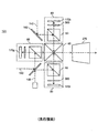
空間光変調デバイスやシリコン上の液晶(LCOS)の場合は、特に、強い光がカウンター電極基板内で熱負荷と応力複屈折を生じる場所で問題が発生し、その基板はそのデバイス自体に対して内部にある。さらに状況を説明すると、図1Bは、従来技術のプロジェクタ101を例示し、入射する照明光ビーム140は、各色に対して、それぞれの変調光学システム80へ方向付けられ、そのプロジェクタは、偏光ビームスプリッタ60(偏光プリズムとしても知られる)、偏光補償器360、及び空間光変調器170g、170b、又は、170rを含むプロジェクタ・サブシステムである。変調光学システム80からの変調ビームはXプリズム65を用いて組み合わされ、投影レンズ270に方向付けられて、表示スクリーン(不図示)に投影される。一般的には、変調光学システム80内のコンポーネントの偏光の性質及び特性は、プロジェクタ101によって供給されるスクリーン上の偏光コントラストを決定する。
In the case of spatial light modulation devices and liquid crystals on silicon (LCOS), problems arise especially where intense light causes thermal loads and stress birefringence in the counter electrode substrate, which substrate is against the device itself. Inside. To further illustrate the situation, FIG. 1B illustrates a
カウンター電極基板(不図示)は光学ガラスの薄いプレートであり、LCD空間光変調器170g、170b及び170r内のシリコン基板と平行に配置される。そして、液晶物質は、シリコン内に(又はその上に)形成されるピクセル構造と同様に、これらの基板の間の薄い隙間を埋める。対向する電極基板は、パターン透明電極(一般的にはITOの)で被覆され、電場が電極間に印加されることを可能にし、ピクセル的な基礎上で液晶分子の方向をコントロールする。
The counter electrode substrate (not shown) is a thin plate of optical glass and is arranged in parallel with the silicon substrate in the LCD spatial
この構造は低い光強度で良好に動作し、そうして、ピクセルによって支配される偏光方向が、光が対向する電極基板を通過するように、維持され、そして、結果の偏光画像光は、偏光ビームスプリッタ、分析器、又はスイッチといった下流の偏光光学系に衝突することができ、偏光画像光は意図する方向を有する。しかし、高い光強度では、カウンター電極基板を透過する光の部分は、吸収され、充分な内部過熱により、応力複屈折を引き起こし、変わって、偏光方向を変化させる。 This structure works well at low light intensity, so that the polarization direction dominated by the pixels is maintained so that the light passes through the opposing electrode substrate, and the resulting polarized image light is polarized It can impinge on downstream polarization optics, such as a beam splitter, analyzer, or switch, and the polarized image light has the intended direction. However, at high light intensity, the portion of the light that passes through the counter electrode substrate is absorbed and causes enough birefringence to cause stress birefringence, which in turn changes the polarization direction.
この課題を認識し、Schmidt他の米国特許5,576,854(特許文献9)は最適なガラスを識別する方法を提案し、そのガラスは、LCOSパネルのカウンター電極基板を製作するように使用される。特に、彼らは候補となるガラスを識別する性能指数Mを提案し、以下の積で与えられる: Recognizing this challenge, Schmidt et al., US Pat. No. 5,576,854, proposed a method for identifying optimal glass, which was used to fabricate counter electrode substrates for LCOS panels. The In particular, they propose a figure of merit M that identifies candidate glasses and is given by the following product:

投影ディスプレイにおけるガラスの選択と熱応力複屈折との関係は、Displays, Vol.23, pp.151-159, 2002に発行された、R. Cline他による”Thermal Stress Birefringence in LCOS Projection Displays”の論文で探求されている。この論文は、投影ディスプレイシステムにおける偏光ビームスプリッタ60(図1B)又はフィリップスプリズムアセンブリ55(図1A)の使用に適切なガラスを特定することに関連する。特に、著者は、候補となるガラスを評価する拡張した性能指数を導入し、その性能指数は、熱膨張係数(ρ)、応力光学係数(κ)、弾性係数(E)だけでなく、ガラスの熱伝導性(K)、光吸収率(α)、及びポアソン比(μ)を含む: The relationship between glass selection and thermal stress birefringence in projection displays is described in the “Thermal Stress Birefringence in LCOS Projection Displays” paper by R. Cline et al. Published in Displays, Vol.23, pp.151-159, 2002. Is being explored by. This article relates to identifying a suitable glass for use of the polarizing beam splitter 60 (FIG. 1B) or the Philips prism assembly 55 (FIG. 1A) in a projection display system. In particular, the author introduces an expanded figure of merit that evaluates the candidate glass, which includes not only the coefficient of thermal expansion (ρ), the stress optical coefficient (κ), the elastic modulus (E), but also the glass Includes thermal conductivity (K), light absorption rate (α), and Poisson's ratio (μ):
対照的に、Aastuen他の米国特許7,357,511(特許文献10)では、発明者は、充分に低い応力複屈折(例えばSchott SK5又はSchott BK7)のためCline他により提案されるガラスは、実際には不適当であり、これらの代替ガラスからのコントラスト劣化は実際には大きすぎると示唆している。そして、Aastuen他は、代替の変調光学システム80を提案し、そのシステムでは、偏光ビームスプリッタ60の偏光コントラストは、偏光ビームスプリッタ60と空間光変調器170との間に偏光補償器360を供給することにより(図1B参照)、プリズムを含むガラスの応力複屈折に関して改善することができ、そこには熱的に生じる応力複屈折も含む。彼らは、4分の1波長の遅延特性を有する偏光補償器360が、応力複屈折に対して充分な補償を与え、そうして、プリズムガラスの選択が、Schott SF-57のような低い応力光学係数(κ)のガラスにもはや限定されないことを実証している。
In contrast, in U.S. Pat. No. 7,357,511 to Aastuen et al., The inventor states that the glass proposed by Cline et al. Because of sufficiently low stress birefringence (eg Schott SK5 or Schott BK7) In practice it is inappropriate and suggests that the contrast degradation from these alternative glasses is actually too great. Have proposed an alternative modulation
また、マイクロリソグラフィーの領域も含み、不所望の複屈折が投影空間以外の領域で画像品質の問題を発生していることに留意する。例えば、Allan他の米国特許6,785,051(特許文献11)は、200nmUVリソグラフィーを目的とする屈折/反射イメージングシステムについて説明している。そうしたスペクトル範囲では、利用可能な光学物質については非常狭い範囲の選択が、大きな固有複屈折を示すフッ化カルシウム(CaF2)のような結晶物質によって支配される。光学系内の累積複屈折や偏光状態の変化を低減するため、Allan他は、1つ又は複数の補正光学要素を提案し(光学プレート又はビームスプリッタ)、その要素は、同じタイプの本質的に複屈折な物質から作製される。この例では、補正光弾性複屈折は、外部に適用される応力又はひずみによって供給され(引張、圧縮、又は、せん断応力から)、機械的固定具、圧電アクチュエータ、熱要素、又は、他の応力発生器によって、その補正要素に与えられる。 It should also be noted that undesired birefringence causes image quality problems in areas other than the projection space, including microlithographic areas. For example, U.S. Pat. No. 6,785,051 to Allan et al. Describes a refractive / reflective imaging system aimed at 200 nm UV lithography. In such a spectral range, a very narrow range of choices for available optical materials is dominated by crystalline materials such as calcium fluoride (CaF 2 ) that exhibit large intrinsic birefringence. In order to reduce cumulative birefringence and polarization state changes in the optical system, Allan et al. Proposed one or more correcting optical elements (optical plates or beam splitters) that are essentially of the same type. Made from birefringent material. In this example, the corrected photoelastic birefringence is supplied by externally applied stress or strain (from tensile, compression, or shear stress), mechanical fixture, piezoelectric actuator, thermal element, or other stress It is given to the correction element by the generator.
同様に、Brunotte他の米国特許6,879,379(特許文献12)は、CaF2のような本来的に複屈折な物質と補正要素とを含むレンズ要素を用いた、UVマイクロリソグラフィック・イメージング・システムを開示する。その本来的な複屈折は、位置と角度に関する不所望の偏光回転効果を伝える。この例では、補正要素は光学プレート又はレンズであり、アパーチャストップに最も近く位置付けられ、またCaF2から製作される。そして、機械的応力が、圧電アクチュエータを用いてパルス方式で印加され、その結果、応力複屈折が、本来的な複屈折によって生ずる角度依存の偏光効果を補償する要素につたえられる。 Similarly, Brunotte other U.S. patents 6,879,379 (Patent Document 12), using a lens element comprising a inherently birefringent material such as CaF 2 and the correction element, UV microlithographic imaging・ Disclose the system. Its inherent birefringence conveys an undesirable polarization rotation effect with respect to position and angle. In this example, the correction element is an optical plate or a lens, positioned closest to the aperture stop, also fabricated from CaF 2. Mechanical stress is then applied in a pulsatile manner using a piezoelectric actuator, so that stress birefringence is a factor that compensates for angle-dependent polarization effects caused by intrinsic birefringence.
興味深いことに、Brunotte他(‘379)(特許文献12)とAllan他(‘051)(特許文献11)のソリューションは、本来的に複屈折な物質の限定的なセットを用いて、イメージングシステムに適用される。比較すると、Schmidt他(’854)(特許文献9)、Cline他、及び、Aastuen他(’511)(特許文献10)によって提案されるソリューションは、低パワーのアプリケーションを目的とするランプベースの投影システムの状況で開発されたが、潜在的にはデジタルシネマに拡張可能である。しかし、これらのソリューションは、プロジェクタ101の変調光学システム80の内部の光学要素(カバーガラスとプリズム)だけを対象としている。
Interestingly, the solution of Brunotte et al. ('379) (12) and Allan et al. (' 051) (11) uses an intrinsically birefringent limited set of materials for imaging systems. Applied. In comparison, the solution proposed by Schmidt et al. ('854) (Claim 9), Cline et al., And Aastuen et al. (' 511) (Patent Document 10) is a lamp-based projection for low power applications Although developed in the context of the system, it can potentially be extended to digital cinema. However, these solutions target only the optical elements (cover glass and prism) inside the modulation
レーザ投影システムでは、局部的な光強度とパワー密度は、白色光システムに比べて、感知できるほど高くなり、それは、レーザ光のコヒーレンス又はフォーカスパワーのためであり、さらに、熱効果が光学システム全体に生じることがある。極端な例では、非線形の光学物質内での光学的な自己集束効果が、光学損傷や光学破壊を発生することがある。 In a laser projection system, the local light intensity and power density are appreciably higher than in a white light system, because of the coherence or focus power of the laser light, and further, the thermal effect is the overall optical system. May occur. In extreme cases, optical self-focusing effects in nonlinear optical materials can cause optical damage and destruction.
レーザベースのデジタルシネマプロジェクタの例では、自己集束のような永久損傷メカニズムはおそらくは密接な関係は無いが、熱的に引き起こされた応力複屈折のような他の熱的効果は、他の光学要素に影響を及ぼし、その光学要素には、プリズムアセンブリ、空間光変調器、又は、カバープレート、又はそのカウンター電極基板のような変調光学サブシステムの中に存在するもの以外のコンポーネントを含む。特に、多数の複雑なレンズ要素を含むイメージングレンズアセンブリであって、強いレーザ光をイメージするよう負荷が掛けられ、一方で、熱的に発生した応力複屈折や結果的に生じる偏光効果を受けない、イメージングレンズアセンブリの設計と使用は、デジタルシネマのパワーレベルで関心事であり、そのパワーレベルは、応力複屈折に対して以前に扱われた場合よりもずっと高いパワーレベルである。レンズ設計の当業者に知られているように、イメージングレンズアセンブリは、非平面レンズ要素の構成を利用し、その物質、厚さ、曲率、及び、相対配置は慎重に設計されて、収差と回折に関して、所望の画像品質を供給する。しかし、イメージングレンズシステムとその構成するレンズ要素の設計に関して、熱的に生じた応力複屈折を更にコントロールする追加的な複雑さは問題であって、いずれの先行技術にも教示も示唆もない。 In the example of a laser-based digital cinema projector, permanent damage mechanisms such as self-focusing are probably not closely related, but other thermal effects such as thermally induced stress birefringence are The optical elements include components other than those present in the modulating optical subsystem, such as prism assemblies, spatial light modulators, or cover plates, or counter electrode substrates thereof. In particular, an imaging lens assembly that includes a large number of complex lens elements that are loaded to image intense laser light, while not subject to thermally generated stress birefringence and the resulting polarization effects The design and use of an imaging lens assembly is of concern at the power level of digital cinema, which is a much higher power level than previously handled for stress birefringence. As known to those skilled in the art of lens design, imaging lens assemblies utilize a configuration of non-planar lens elements, whose materials, thickness, curvature, and relative placement are carefully designed to provide aberration and diffraction. For the desired image quality. However, with respect to the design of the imaging lens system and its constituent lens elements, the additional complexity of further controlling thermally generated stress birefringence is a problem and neither teaches nor suggests any prior art.
本発明の課題は、上記の問題点を解決することである。 An object of the present invention is to solve the above problems.
本発明は、熱に起因する応力複屈折の感受性を低減した結像レンズを設計する方法を示し、対物面を画像面に結像し、前記結像レンズは前記対物面と前記画像面との間に位置する開口絞りと、前記開口絞りの対物面側に位置する第1レンズ要素群と、前記開口絞りの画像面側に位置する第2レンズ要素群とを有し、前記方法は:
前記レンズの幾何学的特性を記述する1組のレンズ設計属性を定義するステップと;
1組のレンズ性能基準を定義するステップであり、該レンズ性能基準には1つ以上の画像品質性能基準と熱により引き起こされる応力複屈折の基準とを含む、ステップと;
熱応力複屈折メトリックにより特徴付けられるように、熱により引き起こされる応力複屈折への僅かな感受性を有する第1の候補ガラスの組を定義するステップと;
前記熱応力複屈折メトリックにより特徴付けられるように、熱により引き起こされる応力複屈折に対して僅かな感受性よりも大きいが、最大でも中程度の感受性を有する、第2の候補ガラスの組を定義するステップと;
前記第1の候補ガラスの組から、前記開口絞りのすぐ近くに位置する、前記第1及び第2のレンズ要素群内のレンズ要素のガラスを選択するステップと;
前記第1又は第2の候補ガラスの組から、前記開口絞りのすぐ近くに位置しない、前記第1及び第2のレンズ要素群内のレンズ要素のガラスを選択するステップと;
コンピュータプロセッサを用いて、前記定義されたレンズ要素基準を満たしながら前記レンズ設計属性を達成する結像レンズの設計を決定するステップであって、前記レンズ設計は、前記第1及び第2のレンズ要素群内のレンズ要素の、厚さ、間隔、形状、及びガラスを特定する、ステップと、を含む。
The present invention shows a method for designing an imaging lens with reduced sensitivity to heat-induced stress birefringence, and forms an objective surface on an image plane, and the imaging lens is formed between the objective plane and the image plane. The method includes: an aperture stop positioned between; a first lens element group positioned on the object plane side of the aperture stop; and a second lens element group positioned on the image plane side of the aperture stop, the method comprising:
Defining a set of lens design attributes describing the geometric properties of the lens;
Defining a set of lens performance criteria, the lens performance criteria including one or more image quality performance criteria and a criterion for heat-induced stress birefringence;
Defining a first set of candidate glasses having a slight susceptibility to thermally induced stress birefringence as characterized by a thermal stress birefringence metric;
Define a second set of candidate glasses that are more than slightly sensitive to heat-induced stress birefringence but at most moderate sensitivity as characterized by the thermal stress birefringence metric Steps and;
Selecting a glass of lens elements in the first and second lens element groups located in the immediate vicinity of the aperture stop from the first set of candidate glasses;
Selecting from the first or second set of candidate glasses a glass of lens elements in the first and second lens element groups that are not located in the immediate vicinity of the aperture stop;
Using a computer processor to determine a design of an imaging lens that achieves the lens design attributes while satisfying the defined lens element criteria, the lens design comprising the first and second lens elements Identifying the thickness, spacing, shape, and glass of the lens elements in the group.
結像レンズが偏光を用いて画像を生成するよう使用されるとき、その画像レンズの性能は、その画像光の吸収から生じる熱の変化に重大な影響を受けないという利点を有する。 When an imaging lens is used to produce an image with polarized light, the performance of the image lens has the advantage that it is not significantly affected by thermal changes resulting from absorption of the image light.
さらに、そうした結像レンズは、応力複屈折に起因する偏光解消による左目と右目の画像間の好ましくないクロストークを生じることなく、立体視投影システムに使用できるという利点を有する。 Furthermore, such an imaging lens has the advantage that it can be used in a stereoscopic projection system without undesired crosstalk between the left and right eye images due to depolarization due to stress birefringence.
低減した複屈折の感度が、受容可能な画像品質レベルを同時に達成しつつ、達成されるという追加的な利点も有する。 There is also the added benefit that reduced birefringence sensitivity is achieved while simultaneously achieving an acceptable image quality level.
本発明は、以下に示される例示的実施形態の詳細な説明からより容易に理解され、それは添付の図面とともに考慮されるだろう:
本説明は詳しくは、本発明に従った装置の部分を形成する要素に向けられるか、又は、その装置とより直接的に協力する要素に向けられる。理解されるべきは、具体的に示されない又は説明されない要素は、当業者に周知の各種の形態をとってもよいことである。 This description is specifically directed to elements that form part of a device according to the present invention, or to elements that cooperate more directly with the device. It should be understood that elements not specifically shown or described may take various forms well known to those skilled in the art.
本発明は、本明細書で説明される実施形態の組合せを含む。“或る特定の実施形態”及び類似への言及は、本発明の少なくとも一つの実施形態にある特徴へ言及する。“一実施形態”又は“特定の実施形態群”又は類似のものについての別々の参照は、必ずしも同じ実施形態又は実施形態群に言及するものではない。しかし、そのように示唆されているか、又は、当業者に特に明らかである場合でなければ、そうした実施形態群は相互に排他的ではない。“方法”又は“方法群”及び類似のものに言及する際の、単数形又は複数形の使用は、限定的ではない。留意すべき点として、特に断りの無い限り、又は、文脈上必要とされる場合を除き、“又は”の語は、本明細書中では非排他的な意味で用いられる。 The present invention includes combinations of the embodiments described herein. Reference to “a particular embodiment” and the like refers to a feature in at least one embodiment of the invention. Separate references to “one embodiment” or “a specific group of embodiments” or the like do not necessarily refer to the same embodiment or group of embodiments. However, such embodiments are not mutually exclusive unless so suggested or otherwise apparent to those skilled in the art. The use of the singular or plural number when referring to a “method” or “method group” and the like is not limiting. It should be noted that the word “or” is used herein in a non-exclusive sense unless otherwise noted or unless otherwise required by context.
本発明をより良く理解するため、全体の文脈を、本発明の装置と方法が動作可能である範囲内で説明することは有益である。図2の概略図は、プロジェクタ102の基本構成を示しており、そのプロジェクタは本発明の多数の実施形態で使用される。3つの照明アセンブリ110r、110g、及び、110bが示され、各々は、主要色の赤色、緑色、又は、青色(RGB)の1つを各光源アセンブリ115から供給する。その光源アセンブリ115は、1つ以上の光源を有し、詳しくはレーザ光源デバイスである(そのレーザ光源デバイスは図2には示されないが、図3Aと3Bに代表的な方法で示される)。
For a better understanding of the present invention, it is useful to describe the overall context to the extent that the apparatus and method of the present invention are operable. The schematic diagram of FIG. 2 shows the basic configuration of the
図3Aは、複数のレーザアレイ120と120´からの光を組み合わせ、レーザ結合アセンブリ125を形成する、或る手法を示し、そのレーザ結合アセンブリは、光源アセンブリ115の一部分である(図2)。数ワット又はより多くの出力の、高パワー半導体(又はソリッドステート)のレーザアレイが、長年の間、赤色及び赤外線(IR)で容易に利用可能だった。これらのレーザは、一般的に、マルチモードレーザエミッタ122による単一モードの単一列を含む。しかし、高パワーで小型の緑色及び青色のレーザアレイだけが今になって利用可能になってきている。今までは、Necselの前述のレーザは、IRポンプ、周波数2倍、VECSEL(垂直拡張型空洞表面発光レーザ)のタイプのレーザであり、特別な期待を示してきた。重要なコンポーネントの加熱とパッケージの問題のため、現在利用可能なプレ商品化デバイスは、制約的な構造を有し、2つの平行な列のレーザエミッタ122を供給する(列ごとに24エミッタ)。
FIG. 3A shows one approach to combining light from
その構成レーザアレイからの出力光ビームを近接して配置することは光学的には有利であるが、レーザアレイ120を相互に機械的に分離し、熱のクロストークと集中した熱負荷を低減することも望ましい。また、光源アセンブリ115(図2)を、電子デリバリとコネクション、関連する加熱と同じく、熱に敏感な光学投影システムから分離し、投影エンジンの光学性能を許容することは望ましい。図3Aでは、1つ以上の分散型ミラー160が使用され、追加のレーザアレイ120´の光軸をレーザアレイ120と一致して位置づけ、多数の光ビーム140を供給し、各々は複数の個別の光ビーム140´を含み、関連するアパーチャ130を有する照明レンズ150へ一緒に方向付けられ、その照明レンズは照明アセンブリ110r、110g、及び、110b(図2)それぞれのコンポーネントである。
Although it is optically advantageous to place the output light beams from the constituent laser arrays close together, the
次に、図3Bは、他の実施形態による例示的な照明アセンブリ110の一部を表す。その照明アセンブリ110は、2つのレーザ結合アセンブリ125を含む、所定の色の光源アセンブリ115を有する。そうした構成を用いて、パワー出力は増大され、より高いスクリーン・ルーメン条件を有する大規模スクリーンをサポートすることができる。この例では、2つのレーザ結合アセンブリ125の各々は、各側面でウインドウカット及び反射カットされた(完全な内部反射によって作用する)プリズム127を利用し、レーザアレイ120内のレーザエミッタ122からの光ビーム140の向きを共通の光路の下手へ変える。2つのレーザ結合アセンブリ125からの出力光は、照明ビーム結合器135によって共通光路の下手へ方向付けられ、照明レンズ150や光インテグレータ155で表されるような他の照明光学系へ方向付けられる。照明ビーム結合器135は、スペクトル的に(そのケースでは、レーザ組合せアセンブリ125のレーザアレイ120は、中心波長の反対側にクラスタ化される)、空間的に、又は偏光による方法を含む様々な手法で光ビーム140を組み合わせることができる。或るパスは選択的な2分の1波長板137を有することができる。
Next, FIG. 3B depicts a portion of an
図2と3Bとを組み合わせて考えると、各照明アセンブリ110r、110g、及び、110bは、一般的には1つ以上の、透過する光ビームを形成し方向付ける照明レンズ150、光インテグレータ155、及び、更なる照明レンズ150、ミラー160を含み、それらは一緒に、照明光を光軸145に沿って関連する空間光変調器170に方向づける。例えば、光源アセンブリ115から入ってくる光は、照明レンズ150を用いて、光インテグレータ155に方向付けられる。結果的に生じる均一光は、光インテグレータ155の出力アパーチャを満たす。次に、その出力アパーチャは、光軸面の或る領域に再画像化され、そこに空間光変調器170が配置される。照明レンズ150と光インテグレータ155は、石英ガラスを用いて形成され、その結果、これらの要素の中に誘発される応力複屈折から発生するおそれのある如何なる偏光劣化効果をも低減する。
2 and 3B, each
空間光変調器170は、微小電気機械システム(MEMS)デバイスであってもよく、例えば、DLPや他のタイプの反射型MEMSデバイスであり、反射又は回折により変調する如何なるタイプのMEMS変調器をも含む。空間光変調器170はまた、LCDタイプのデバイス、又は、他の技術のデバイスであってもよい。DLPタイプのデバイスの例では、変調は、表示面に向けられる“On”状態又は画像光、及び、ビームダンプ(不図示)に向けられる“Off”状態光を供給する。プロジェクタ102が偏光光源の方向を切替え、立体画像投影(3D)をドライブする場合は、“偏光状態中立”の変調器デバイスが望ましい。詳しくは、空間光変調器170が好ましく、ピクセルの偏光状態を変調することにより、各ピクセルで光を変調せず、そうして、如何なるピクセルの入射光の偏光状態への如何なる変化も気づかず小さくなる。このことは、空間光変調器170が、入射光の偏光状態にかかわらず、好ましくは入射光をピクセルベースで等しく変調することを意味する。それ故、観客は、偏光感度グラスを着用し、そうして立体視又は3D画像を観察するものと思われる。また理解されるべき点として、プロジェクタ102は2次元として認識される従来の画像を供給することができる。
Spatial
プロジェクタに外部的に付加した偏光スイッチングアクセサリにより3Dイメージを供給するプロジェクタと異なり、このプロジェクタ102では、照明アセンブリ110からの照明光は偏光されることを目的としている。詳しくは、光源は構成されて、一般的な偏光状態、即ち、この分野の用語で“s−偏光”や“p−偏光”として知られる偏光状態を供給する。照明アセンブリ110は様々な光学系を含むことができ、波長板や偏光子(不図示)を含み、光源の本来の偏光状態を調整し、保持し、又は、強調する。また、照明アセンブリ110は偏光スイッチ139を含むことができ、その偏光スイッチは電気光学的に又は電気機械的に動作され、その結果、光照明空間光変調器170の偏光状態を、s−偏光、p−偏光、又は、3D投影に有用な他の偏光状態(例えば左又は右回転)に変化させる。その結果、好ましくは、照明レンズ150や光源インテグレータ155を含む各種の照明コンポーネントは、偏光が保持される。照明アセンブリ110r、110g、及び、110bの各々の内部の光路は、同じ基本パターンをたどるが、或る色チャンネルからの光源(レーザ)特性と他の色チャンネルとの違いを調整するための相違が存在する。各照明アセンブリ110はそれ自身の偏光スイッチ139を有することができ、その偏光スイッチは互いに同期して動作されてもよく、又は、共通の偏光スイッチ139が複数の色チャンネルに使用されてもよい。
Unlike a projector that supplies a 3D image with a polarization switching accessory externally added to the projector, the
図2に示されるように、照明光は、1つ以上のミラー160の再方向付けにより、空間光変調器170上に方向付けられる。変調された画像光は、空間光変調器170のアドレスされたピクセルにより、透過光に伝えられる画像データを有し、共通の光学路を横断するよう組み合わされ、その光学路は結像レンズ200を通って(投影スクリーンのような)表示面190の上へ通過する。例示の実施形態では、2色性コンバイナー(結合器)165は第1コンバイナー166と第2コンバイナー167とを含み、各コンバイナーは2色性要素であり、適切な薄いフィルムのコーティングを有し、光の波長に応じて光を選択的に透過、又は、反射する。このプロジェクタ102は、光学偏光状態の内部変調を用いて、3D画像コンテンツを供給するように設計されるので、2色性コンバイナー165と結像レンズ200も偏光中立であるべきであり、そうして、これらの要素によっては、効率の違い、偏光コントラスト、又は、画像品質は、わずかしか又は全く生じない。同様に、表示面190は好ましくは偏光保存スクリーンである。
As shown in FIG. 2, the illumination light is directed onto the spatial
ミラー160は光学システムのプレーン内にある必要はないことに留意すべきである。それ故、緑色チャンネルの光路内のミラー160は、プレーンの外にあって、投影レンズ270へ通過する光を遮らず、その他の点は図2に示唆されるだろう。追加的に、2色性コンバイナー165が1組の傾いたガラス板として示されるが、他の例示的構成が用いられてもよく、それにはXプリズム65(図1B)、Vプリズム、又は、フィリップス(又はPlumbicon)タイプのプリズム(図1A)が含まれる。他の実施形態では、ミラー160は、例えば、しばしばフィリップス・プリズムやDLPデバイスと共に組み合わせて使用され、広く使用されるTIR(トータル・インターナル・リフレクション)プリズムのようなプリズムの形態で供給される。
It should be noted that the
図2では、結像レンズ200は多要素アセンブリとして表され、複数のレンズ要素205を含み、対物面の空間光変調器170r、170g、及び、170bを、高倍率(一般的には100x−400x)で画面(表示面190)上に直接に結像する。
In FIG. 2, the
図4は、結像レンズ200の設計について説明し、その実施形態では、結像レンズ200は2つの部分、即ち、リレーレンズ250と投影レンズ270とを含み、それぞれ、多数のレンズ要素205を含み、そのレンズ要素は有限共役で動作し、レンズハウジング240内にアセンブリされる。例えば、リレーレンズ250は設計され、空間光変調器170の対物面からF/6光を集光し結像し、その結果、実空間中間画像260を対応する画面に形成する。次に、この中間画像260は投影レンズ270の対物面であり、その投影レンズは離れた画面(表示面190)に中間画像の拡大画像を供給し、その画面は許容範囲内の焦点深度では名目上の画面である。即ち、空間光変調器170は中間画像260に対して画像共役であり、また、その中間画像は表示面190に対して画像共役である。
FIG. 4 describes the design of
リレーレンズ250は好ましくは、150−200mm又はそれ以上の、長い作動距離を供給し、空間光変調器170の近くで、2色性コンバイナー165とミラー160(図2)の間隔を与える。例示的なリレーレンズ250は、1x又はそれよりやや大きい横倍率で、空間光変調器170を結像し、実中間画像260を供給し、そのサイズは35mm映画フィルムのフレームの画像領域に相当する。その結果、投影レンズ270は、潜在的には、35mmフィルム画像を投影するように設計される従来の投影レンズであってよく、例えば、ドイツのバードクロイツナッハのSchneider-Kreuznachによって現在製造される投影レンズである。
The
図4に表される結像レンズ200は図2のものより複雑に見えるが、実際は、図4のリレーレンズ250と投影レンズ270とは設計、製造がより簡易であり、低コストであり、従って、同等な統一された結像レンズ200が現在業務用のDLPシネマプロジェクタの中にみられる。一つには、高倍率で作動するときよりも、1x近くの倍率で作動する間に長い作動距離を供給する方が簡易であるからである。追加的に、この手法は、中間画像260で又はその近くで、移動ディフューザのような脱スペックル器(デスペックラー)180の挿入に便利な場所を与えて、レーザの脱スペックルを可能にする。このシステムでは、脱スペックル器180は好ましくは、小型レンズアレイであって、まばらに配置される小型レンズを含み、その小型レンズは1つ以上の結像ピクセルのサイズを有する。脱スペックル器180を動作させると、投影レンズ270は好ましくはリレーレンズ250よりも明るいレンズ(〜F/3)である。
The
こうした背景から、実験用のレーザベースのプロジェクタ102が発明者によってアセンブリされテストされ、そのプロジェクタは、図2、3A,及び、3Bに表された一般的な構成を有するが、リレーレンズ250、中間画像260、及び、投影レンズ270を備えた図4の結像レンズ200を利用する。動作中、或るプロトタイプ版のシステムは、偏光コントラストの消失を示した。そうして、プロジェクタが低輝度出力(例えば3000ルーメン)で動作するときは、青色チャンネルの偏光コントラストが〜400:1又はそれ以上になるが、プロジェクタが脱スペックル器180が無い場合で〜6000ルーメン以上のレベルで動作するときは、〜100:1に低下し、脱スペックル器180が動作する場合で〜150:1に低下する。詳しくは、青色光がより高い吸収レベルを有するので、偏光の変化又は消失は、青色イメージに対して最も明らかだった。偏光の変化は、偏光識別グラスを着用した観察者に認識される、投影される立体視画像のクロストーク又はゴーストを発生した。このクロストークは、Real-Dにより提案されるゴースト補正デジタルポストプロセッシング法を用いて改善することができるが、本発明は、好ましいソリューションを与え、内部レンズ設計補正が使用され、そうした補正の必要性を除去する。
Against this background, an experimental laser-based
詳しくは、偏光コントラストは光レベルによって低下するので、このことは、問題は熱的に引き起こされる応力複屈折に起因するという知見と一致する。明らかになるように、或るソリューションを提供し、そのソリューションは、リレーレンズ250と投影レンズ270の設計において、光学的ガラスを選択的に使用することを含む。これらのレンズは両方とも、図4の実施形態で示されるように、一般的にはダブルガウスタイプのレンズである。基本的なダブルガウスレンズは、1800年代にさかのぼり、C.F.Gaussによって、その後Alvan Clarkがその原型を発展した。始めに、C.F. Gaussは、フラウンフォーファー望遠鏡の対物を、その単一の凹凸レンズ設計にメニスカスレンズを付加することにより、改良した。その後、Alvan Clarkは、これらの2つのレンズをとって、背中合わせに配して、ダブルガウス設計を得た。Paul Rudolphは、米国特許583,336(特許文献13)で説明されるように、これをさらに改良し、接合ダブレットを使用して、色収差を補正した。ダブルガウスレンズは、背中合わせになった2つのガウスレンズからなり、開口絞り付近に位置する2群のレンズ要素208を形成し、Rudolphにより実証されるように、2群のレンズ要素は同一であっても良い。
Specifically, since the polarization contrast decreases with light level, this is consistent with the finding that the problem is due to thermally induced stress birefringence. As will become apparent, a solution is provided, which includes the selective use of optical glass in the design of
図5Aは、従来技術のダブルガウスタイプの結像レンズ200を表し、離れた画面(不図示)への光学軸145に沿って対物面195を結像する。一般的な基本形態では、それは、1組の内部の負レンズ要素206bと、外部対の正レンズ要素206aとからなり、その負レンズ要素は、開口絞り230の近くに位置するフリントタイプのガラスであり、その正レンズ要素は、クラウンタイプのグラスからなる。この例では、開口絞り230の一方の側と他方の側のレンズ要素設計(ガウスレンズアセンブリ)は同一ではない。
FIG. 5A represents a prior art double Gauss
図5Bでは、グラスチャート210によって、クラウンとフリントのガラスの有意性が示され、それは“アッベ・ダイアグラム”であって、Schott Glass, Inc.によって公表された広く認識されたガラスチャートデータをプロットしている。クラウンガラス215は低い分散を有し(高いアッベ数vd>50で示される)、一般的には低い屈折率(nd)を有するが、フリントガラス217は比較的高い分散を有し(低いアッベ数 vd<50)、一般的にはより高い屈折率を有する。低フリント又は低クラウンは、中間的な分散特性を有し、中間的なアッベ数vd 〜50の近くで見られる。また、図5Aでは、レンズ要素は、クラウンガラス215を用いて製造されるクラウンレンズ要素220、又は、フリントガラス217から製造されるフリントレンズ要素222の何れか一方として特定される。
In FIG. 5B, the
ダブルガウス設計手法と、光学パワーを多数の要素にスプリットすることとの一般的な調和は、レンズシステムによって付与される光学収差を低減する。それは、今日使用される多数のカメラレンズの基礎を形成し、詳しくは、35mm及び他の小型カメラの大口径の標準レンズである。完全に対称な設計は、コマ、ひずみ、及びTCA(横色収差又はラテラルカラー)を有しない。多数の設計の変形例が存在し、付加された追加レンズ要素を備え、又は、開口絞り230に関する非対称設計を備え、対称性は他の目的を達成するために犠牲になる。例えば、R. Mercadoの米国特許4,704,011(特許文献14)はダブルガウスタイプの写真のレンズについて述べるが、W. Reinecke他の米国特許6,795,255(特許文献15)は、フィルムからの投影画像のためのダブルガウスタイプのムービー・レンズについて述べ、さらに、同一出願人であるD. DeJagerの米国特許5,172,275(特許文献16)は、映画フィルムスキャニングに適用可能な複雑なダブルガウスタイプのレンズについて述べる。
The general harmony between the double Gaussian design approach and the splitting of optical power into multiple elements reduces the optical aberrations imparted by the lens system. It forms the basis for many of the camera lenses used today, and in particular, is a standard lens with a large aperture for 35 mm and other small cameras. A completely symmetric design does not have coma, distortion, and TCA (transverse chromatic aberration or lateral color). Numerous design variations exist, with additional lens elements added, or with an asymmetric design with respect to the
図6Aは、第1の例示的投影レンズ270の設計を示し、その投影レンズは、2群のレンズ要素208を備えたダブルガウスレンズを有し、図4に示される結像レンズ200の内部の投影レンズ270と類似する。投影レンズ270は、2つの内側負レンズ要素402と403とを有し、それらは開口絞り230の付近に位置付けられ、その開口絞りは、フリントレンズ要素222、Schott SF1ガラスを用いて作られる負レンズ要素402、及び、Schott SF2ガラスを用いて作られる負レンズ要素403である。また、投影レンズ270は、4つの外側正レンズ要素400,401,404、及び、405を有し、それらは全てクラウンレンズ要素である。最も右にある最大の正レンズ要素405はOhara S-BSM-10を用いて作られ、他の正レンズ要素400,401、及び、404は、全て、Ohara Glass Inc.のOhara S-LAM-60を用いて作られる。これらのガラスは、Schott GlassのN-SK10及びN-LAF35にそれぞれ同等に近い。光線235は、投影レンズ270を通る光線の経路をトレースするよう示される。
FIG. 6A shows a design of a first
図6Bは変調伝達関数(MTF)のプロット300を示し、そのプロットは図6Aの例示的な投影レンズ270の広帯域MTF特性を表す。回折限界でないときは、MTFは結像領域にわたって、平均して50cy/mmで〜65%であることが分かる。
FIG. 6B shows a modulation transfer function (MTF)
図6Cは第1の例示的なリレーレンズ250の設計を表し、そのリレーレンズはダブルガウスレンズ設計の拡張版であり、図4に示されるリレーレンズ250に類似する。そのリレーレンズ250は、2群のレンズ要素208と視野レンズとを有し、そのリレーレンズは、空間光変調器170(対物面に位置付けられる)の中間画像260を(映像面で)形成するよう用いられる。このレンズ設計は、開口絞り230の周囲に位置付けられる1組の負レンズ要素412と413とを含み、それらはSchott SF4ガラスを用いて作られたフリントレンズ要素222である。リレーレンズ250は、また、クラウンレンズ要素220である正レンズ要素410、411、414、及び、415の集合体を含む。正レンズ要素410と411は、Ohara S-BAL25を用いて作成される。正レンズ要素414はOhara S-LAM54を用いて作成され、さらに、正レンズ要素415はOhara S-NSL3を用いて作成される。リレーレンズ250は、また、中間画像260近くに位置付けられる正視野レンズ416を含み、それはOhara S-LAM54を用いて作成される。2色性コンバイナー165は、また、傾きの無い平面要素で表される。
FIG. 6C represents a first
図6Dは、図6Cのリレーレンズ250の光学特性をMTFプロット300で表す。その光学特性は回折限界に近く、結像領域にわたって、50cy/mmで〜79%の平均MTFを有する。
FIG. 6D represents the optical characteristics of the
前述したように、従来の結像レンズ200は、従来のリレーレンズ250(即ち、図6Cに示されるような)と従来の投影レンズ270(即ち、図6Aに示されるような)とを含み、適度に高いスクリーン輝度レベル(6,000−11,000ルーメン)に対してレーザ光を表示面190に伝達する場合、低いスクリーンルーメンレベルでの〜400:1の偏光コントラストと比較して、青色光偏光画像コントラストの〜150:1又はそれ以下への降下、及び、青色画像ゴーストを経験することが分かった。結像レンズアセンブリが存在しない場合、出力光の偏光コントラストの分離測定は、輝度レベルについてわずかな変化だけ示し、従って、リレーレンズ250と投影レンズ270とが主要な原因であることを確認した。特に、これらの測定は、青色チャンネル(465nm)偏光コントラストは〜100:1に低下するが、緑色と赤色のコントラストレベルは高いままであった(〜300:1)。まとめると、このデータは、偏光コントラストは熱により引き起こされる応力複屈折効果のため低下したことを強く示し、更に高いパワーレベルではより低下するだけであろう。大抵の光学ガラス(最も明白な石英ガラスを除き)が青色において高い吸収を経験するので、応力複屈折は、青色光吸収によって更に容易に引き起こされ得る。その結果、応力複屈折は、様々な程度で、異なる色チャンネルにおける画像品質に影響することがある。
As described above, the
熱により引き起こされる応力複屈折は、温度(T)によりガラス内に生じる屈折率の変化であり、多数のパラメータに機能的に依存し、そのパラメータには波長λ、ガラスの吸収(α)、ガラスの応力感受性(κ)、及び熱膨張の係数(ρ)を含む。また、それは、ガラスを通過する光の光強度(照射)やパワー密度(例えば、W/mm2、lumens/mm2、又はluxの単位)の空間時間分布に依存する。 Thermally induced stress birefringence is a change in refractive index that occurs in the glass due to temperature (T) and is functionally dependent on a number of parameters, such as wavelength λ, glass absorption (α), glass Stress sensitivity (κ) and coefficient of thermal expansion (ρ). It also depends on the spatio-temporal distribution of the light intensity (irradiation) and power density (eg, units of W / mm 2 , lumens / mm 2 , or lux) of light passing through the glass.
図7A−7Fは、例示的な光強度分布を表し、図2,3A、3B、及び、4に表されたプロジェクタ102の光学系を通過することができる。図3A及び3Bに表されるように、レーザ結合アセンブリ125は、多数の出力光ビーム140を生成し、それらは組み合わさってアパーチャ130を満たす、又は、部分的に満たす。レーザアレイ120の構造、即ち、そのレーザアレイはオフセットレーザエミッタ122の1つ以上の空間アレイを有することが可能であるため、表示される光ビーム140の内部の多数の個々の光ビーム140´が得られる。複数のレーザアレイ120からのビームを組み合わせることは、多数の個々の光ビーム140´を増加し、その多くは、アパーチャ130に到達する際に様々な光路長を横断している。個々の光ビーム140´が伝播すると、それらは統合し互いに中にオーバーラップする。光学システム内の位置に応じて、様々な個々の光ビーム140´によって横断される相対光路長と、光ホモジェナイザー、インテグレーター、又は、ディフューザー、幾つかの光ビーム140´、又は、レーザアレイ120のイメージ、又はそれらの組合せの使用とは、他の個々の光ビーム140´やそれらの組合せよりも識別可能であってもよい。その最終結果からは、光強度分布の断面が構造の変化する量を示すことができ、それは光学システム内部の場所に依存する。
7A-7F represent exemplary light intensity distributions that can pass through the optical system of the
この最後の点を説明するため、図7Aは光源アセンブリ115のアパーチャ130の近くのモデル化された光強度分布320を表し、そこでは最内部のレーザアレイ120からの個々の光ビーム140´は、最外部のレーザアレイからの光ビームよりもデフォーカスされる。図7Bは、スライス位置321で図7Aの光強度分布320を通る、2つの断面プロフィール322を示す。多数の光ビーム140´は互いに部分的にオーバーラップするだけで、オーバーラップの大きさは中心から端部まで異なるので、これらの光強度分布320は、空間的に一様であるというよりも、高度に構造化される。
To illustrate this last point, FIG. 7A represents a modeled
図7Aに示されるのと類似するパターンは光学システムの至る所で再発生する。例えば、光インテグレーター155の角度遠距離場では(図3B)、類似するパターンの光強度分布326が図7Eに示されるように出現するが、積分バーの内部の複数の跳ね返りがそれをより複雑にしていた。設計意図によって、その積分バーは、名目上均一な光強度分布323を、図7Cの等高線図に示されるようにその出力フェースとして生成する。図7Dは、図7Cに示されるスライス位置324に対応して、対応する断面プロフィール325を示す。
A pattern similar to that shown in FIG. 7A reappears throughout the optical system. For example, in the angular far field of light integrator 155 (FIG. 3B), a similar pattern of
次に、積分バーの出力フェースでの光強度分布323は再結像し、色チャンネルの空間光変調器170を照射する。リレーレンズ250(図4)は、空間光変調器170を再結像し、組み合わされた白色光画像(画像コンテンツに応じて)を実際の空間中間像260として形成し、その投影レンズ270は引き続き表示面190上に再結像する。リレーレンズ250と投影レンズ270の開口絞り230で、又は、その近くで、システム内に適応される光学拡散、又は、角度平均に応じて、高度に構造化された光強度パターンが現れ、図7Eの光強度分布326をエコーする。例えば、図7Fは、リレーレンズ250の開口絞り230の付近での例示的なモデル化された光強度分布327を示すが、図7Gは、投影レンズ270の開口絞り230の付近での例示的なモデル化された光強度分布328を示す(脱スペックル器180を含まずに)。
Next, the
脱スペックル器180の使用は伝播する光が角度拡大されること、又は、投影レンズ内部で時空間的に平均化されること、又はその両方を可能にすることに留意する。その結果、投影レンズ270の開口絞り230で、又は、その近くでの光強度分布320の微細構造は、輪郭がはっきりしていないかもしれないし、時間的に静止していないかもしれない。それでも、リレーレンズ250と投影レンズ270の内部のレンズ要素205は、高い光学パワー密度を有する通過光を経て、特に開口絞り230の付近では、光強度分布326と327が、光強度分布の微細構造内の多数のピークに集中する光を有することができる。これらの光エネルギーの集中は、熱により生じる光学的な応力複屈折を、これらのレンズアセンブリの至る所で発生させるが、特に、開口絞り230近くのレンズ要素205においてである。
Note that the use of the
複屈折を理解する更なる背景として、光の伝播が波動方程式によって記述でき、式(3)を含み、その式は、平面偏光波Ψ(x、t)を距離xと時間tとの関数として記述し、A(x、t)は振幅関数であり、φ(x、y)は外乱の位相である: As a further background to understanding birefringence, the propagation of light can be described by a wave equation, including equation (3), which expresses the plane polarized wave Ψ (x, t) as a function of distance x and time t. Describe, A (x, t) is the amplitude function and φ (x, y) is the phase of the disturbance:
光が光学材料に入り横断すると、入射角、媒体に対する入射角の偏光方向、その光学材料の屈折率n、及びその材料の厚さに応じて、変化する反射率と位相変化Δφを経験することができる。フレネルの式は、表面反射又は伝達をモデル化し、式(3)の振幅項に影響する。材料又は媒体の屈折率は、基本的には、その媒体中の速度vに対する真空中の光の速度cの比である(n=c/v)。式(4)への代入は屈折率に関して位相を表す: As light enters and traverses an optical material, it experiences a changing reflectivity and phase change Δφ depending on the incident angle, the polarization direction of the incident angle relative to the medium, the refractive index n of the optical material, and the thickness of the material. Can do. The Fresnel equation models surface reflection or transmission and affects the amplitude term in equation (3). The refractive index of a material or medium is basically the ratio of the speed of light c in a vacuum to the speed v in that medium (n = c / v). The substitution into equation (4) represents the phase with respect to the refractive index:
複屈折物質は偏光に関して非等方性物質である。即ち、複屈折は屈折率の方向性変化(Δnsp=ns−np=nx−ny)であり、固有の物質特性、複屈折性のサブ波長構造、又は、発生される機械的応力によって供給され得る。遅延特性は結果的に生じる位相変化Δφであり、距離(R=Δφλ)として表現され、その位相変化Δφ(x、d、λ)=2πd(Δn/λ)である。例えば、π/2(即ち90°)位相変化Δφが適切に方向付けられた複屈折要素(波長板)によって供給され、その複屈折要素は4分の1の波の遅延特性を有し、それは550nmで〜138nmの遅延特性に等しい。
A birefringent material is an anisotropic material with respect to polarization. That is birefringence directional change in refractive index (Δn sp = n s -n p = n x -n y), specific material properties, birefringence of sub-wavelength structure or mechanical generated It can be supplied by stress. The delay characteristic is the resulting phase change Δφ, expressed as a distance (R = Δφλ), and the phase change Δφ (x, d, λ) = 2πd (Δn / λ). For example, a π / 2 (
特に、均一な温度のアプリケーションは、接合要素のような光学部品の機械的応力σにおける変化を生じ、その変化は、その要素及び/又は取り付け物質の間の熱膨張係数の不一致に起因する。温度勾配は、前述した光強度分布微細構造に関連づけられるように、単一の均一な要素内に応力も引き起こす。製造又は加工プロセスの間に与えられる残留応力、又は、圧力荷重、慣性荷重、又は振動荷重の応力の状態は、光学要素内に複屈折を発生させ得る。本質的に、機械的に引き起こされたものであれ残留であれ、応力の影響は、光学素材の屈折率を変化させるだろう。 In particular, uniform temperature applications result in a change in mechanical stress σ of an optical component such as a bonding element, which change is due to a coefficient of thermal expansion mismatch between the element and / or the attachment material. The temperature gradient also causes stress within a single uniform element, as is related to the light intensity distribution microstructure described above. Residual stress applied during the manufacturing or processing process, or stress, inertial or vibrational stress conditions can cause birefringence in the optical element. In essence, whether mechanically induced or residual, the effects of stress will change the refractive index of the optical material.
この例では、プロジェクタ102のリレーレンズと投影レンズの内部の充分な温度のアプリケーションは、特に局所的領域では、熱により引き起こされる光学応力複屈折を生じる。引き起こされる複屈折差は、2つの空間近接位置の間の、主な機械的応力、又は、応力テンソルの引き起こされる差、Δσ1,2=(σ1(x、y、z)−σ2(x、y、z))に直接的に比例し、式(6)で与えられる;
In this example, the application of sufficient temperature inside the relay lens and projection lens of
引き起こされる温度変化ΔTは光吸収に関連することができる。振幅関数A(x、t)は拡張することが可能で、光吸収αへの依存性を示す: The induced temperature change ΔT can be related to light absorption. The amplitude function A (x, t) can be extended and shows a dependence on the light absorption α:
ボリューム発熱Q(x)が以下に示され、単位はW/m2であり、物質の厚さx内に吸収される光から得られ、光強度I(x)、内部透過率ti、又は、吸収係数αの関数として表される:
The volume exotherm Q (x) is shown below, the unit is W /
式(11)を式(7)に代入することで、引き起こされる応力複屈折を入射する光強度と物質吸収に結びつける: By substituting equation (11) into equation (7), the induced stress birefringence is linked to incident light intensity and material absorption:
式(12)では、距離xは物質内部の位置であって、式(9)で与えられる強度と式(11)で与えられる温度変化とが、位置の関数として、応力複屈折Δnの局所的変化を生ずるという事実に関連する。メトリックスM1又はM2にxを含むことは、様々なレンズ要素のガラス選択に関して、少しだけの洞察を与えるだろう。 In the equation (12), the distance x is a position inside the substance, and the intensity given by the equation (9) and the temperature change given by the equation (11) are expressed as local functions of the stress birefringence Δn as a function of the position. Related to the fact that changes occur. Including x in the metrics M 1 or M 2 will give a little insight regarding the glass selection of the various lens elements.
中間的な熱応力複屈折メトリック、M3=M1・Lは、より薄いレンズ要素(厚さLよりも小さい)が、より高いM1の値を許容することができることを示す。しかし、後に分かるように、M1とI0の変動は、その選択と設計プロセスを特徴付ける傾向がある。 The intermediate thermal stress birefringence metric, M 3 = M 1 · L, indicates that thinner lens elements (smaller than thickness L) can tolerate higher M 1 values. However, as will be seen later, variations in M 1 and I 0 tend to characterize the selection and design process.
第2のメトリックM2は、レンズ要素205の中に存在するパワー密度を計算にいれ、そのパワー密度は、リレーレンズ250と投影レンズ270のレンズアセンブリを介して変化し得る。レンズ内の光強度分布が示すように(図7A−7E参照)、最高光強度を有する微細構造は開口絞り230の近くで発生する。その結果、発明者は、ガラスの選択は、これらの領域内のレンズ要素に対して最も重要であることを発見した。それ故、ピーク光強度(I0)が合理的に推測できる場合は、強度重み付けされた熱応力複屈折メトリックM2は有用であることが判明した。
The second metric M 2 takes into account the power density present in the
発明者は、有限要素分析(FEA)を用いて、図6Aの投影レンズ270内の光吸収から、温度により引き起こされる応力を熱力学的にモデル化した。このモデル化は、投影レンズ270の開口絞り230に最も近い負レンズ要素402と403を通過する光学的流束レベルが、最も外側の正レンズ要素400と405を通過する光レベルよりも8x(又はそれ以上)高くなり、ΔTの局所的な温度変化を〜5℃にするということを示した。今度は、これらの局所的温度変化は機械的応力、及び、複屈折の屈折率変化Δnを生じる。
The inventor thermodynamically modeled the stress caused by temperature from light absorption in the
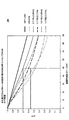
こうした背景により、図8A−8Dで与えられる表は、主要なパラメータとともに、現在のガラスの種類に関するデータを名前で与え、そのパラメータには、それらの屈折率nd、アッベ数νd、内部透過率ti、吸収α(α=−ln(ti)/x)、応力光学係数κ、熱伝導率K、熱膨張係数(CTE)ρ、ポアソン比(μ)、ヤング係数(E)、及び、ガラスだけの性能指数M1を含む。吸収係数値(α)は、λ=460nmでの内部透過率の値を用いて計算された。他の評価波長を使用することもできるが、大抵のガラスはUVから青色までのスペクトル範囲での内部吸収の増大を経験し、従って、緑色や赤色のスペクトル範囲に比べて、応力複屈折の可能性を増大した。図8Aは、低い応力複屈折感受性をもつガラスの集合に対して、様々なガラス特性を示す。図8Bは、中程度(適度な)及び高い応力複屈折感受性をもつガラスの集合に対して、同じ特性を示す。図8Cと8Dは、それぞれ、図8Aと8Bのガラスに対して、熱応力複屈折メトリックスM1’、M1’’、及び、M1の計算値を示す。 With this background, the tables given in FIGS. 8A-8D give data about the current glass type by name, along with the main parameters, which include their refractive index n d , Abbe number ν d , internal transmission. Rate t i , absorption α (α = −ln (t i ) / x), stress optical coefficient κ, thermal conductivity K, thermal expansion coefficient (CTE) ρ, Poisson's ratio (μ), Young's modulus (E), and , including a figure of merit M 1 of only glass. The absorption coefficient value (α) was calculated using the value of the internal transmittance at λ = 460 nm. Although other evaluation wavelengths can be used, most glasses experience increased internal absorption in the spectral range from UV to blue, thus allowing stress birefringence compared to the green and red spectral ranges. Increased sex. FIG. 8A shows various glass properties for a collection of glasses with low stress birefringence sensitivity. FIG. 8B shows the same properties for a collection of glasses with moderate (moderate) and high stress birefringence sensitivity. Figure 8C and 8D, respectively, with respect to the glass of FIG. 8A and 8B, the thermal stress birefringence metrics M 1 ', M 1'' , and shows the calculated values of M 1.
図8A−8Dの表は、SchottとOharaのガラスカタログを組み合わせて、入手可能なガラス(<15%)の部分集合を示し、低い熱により引き起こされる応力複屈折に対して有利な特性を有する、ガラスの不均衡な配分を特徴づける。最も一般的なガラスの1つである、Schott BK-7ガラスは、性能指数M1の充分に低い値(〜0.51x10⁻⁶W−1)を有するが、新しい無鉛ガラス(例えばN-SF2やN-SF4)はそれらが置き換える元のガラス(SF-2やSF-4)よりも高いM1値を有する傾向がある。図8A−8Dの表は、Schott又はOharaのガラスだけを含むが、他のメーカーから入手可能な代替的又は同等のガラスが分析され設計に適切に使用されることも可能である。 The tables of FIGS. 8A-8D combine the Schott and Ohara glass catalogs to show a subset of available glass (<15%) and have advantageous properties against stress birefringence caused by low heat. Characterize the unbalanced distribution of glass. One of the most common glasses, Schott BK-7 glass, has a sufficiently low value of figure of merit M 1 (˜0.51 × 10 −6 W −1 ), but new lead-free glass (eg N-SF 2) And N-SF4) tend to have higher M 1 values than the original glass they replace (SF-2 or SF-4). The tables in FIGS. 8A-8D include only Schott or Ohara glasses, but alternative or equivalent glasses available from other manufacturers can be analyzed and used appropriately in the design.
図8A−8Dの表のガラスは、また、それらがクラウン又はフリントであると考えられるかどうかに応じて、識別される。このガラスメトリックによって、熱により引き起こされる応力複屈折を最小化することに関して、最も良好な可能性のガラスは、引き続き、石英ガラス(Schott Lithosil-Qによって代表される)とSchott SF-57(又はその同等物、例えばOhara PBH56)であり、なぜならそれらは非常に低い又は無視できるほどの熱応力複屈折メトリック値(M1<0.1x10⁻⁶W−1)を有するからである。これらのガラスはSchmidtその他により示されたガラスと同じものである。入手可能なガラスのあらゆる種類をほぼ網羅するこの表を分析すると、ガラスだけの熱応力複屈折メトリックM1は25,000:1の範囲にわたって、最良のガラス(Lithosil; M1〜0.001x10⁻⁶W−1)から最悪のガラス(Ohara S-NPH2; M1〜28.5x10⁻⁶W−1)まで変化する点に留意する。とりわけ、石英ガラス、SF-57、及び、PBH56を含む、無視できるほどの応力複屈折感受性を有するガラス群(M1≒0.001x10⁻⁶W−1から0.05x10⁻⁶W−1まで)から、最良の低い応力複屈折感受性を有するガラス群、例えばSchott LLF1やOhara S-NSL36のようなガラス(M1≒0.36x10⁻⁶W−1から0.46x10⁻⁶W−1まで)まで、M1の値には〜8x又はそれ以上の飛躍が存在する。
The glasses in the tables of FIGS. 8A-8D are also identified depending on whether they are considered to be crowns or flints. With this glass metric, regarding the minimization of heat-induced stress birefringence, the best possible glasses continue to be quartz glass (represented by Schott Lithosil-Q) and Schott SF-57 (or its Equivalents, for example Ohara PBH56), because they have very low or negligible thermal stress birefringence metric values (M 1 <0.1 × 10 −6 W −1 ). These glasses are the same as those shown by Schmidt et al. Analyzing this table, which almost covers all types of glass available, the thermal stress birefringence metric M 1 of the glass alone is over the range of 25,000: 1, with the best glass (Lithosil; M 1 -0.001 × 10 − Note that it varies from 6 W −1 ) to the worst glass (Ohara S-
また、図8C−8Dの表は、2つの構成性能指数メトリックM1’とM1’’とを含む。第1の構成性能指数はM1’=ρκαであり、主要なパラメータのみからなる:熱膨張係数(ρ)、応力光学係数(κ)、及び吸収係数(α)、それらの値は、様々なガラスの中で、それぞれ、〜30x、〜200x、及び、〜950xで広く変化する。第1の構成性能指数M1’に関して、石英ガラスは、その吸収とCTEがともに非常に低いので、最小の値を有するが、SF-57とPBH56はその応力光学係数が低いので良好である。同様に、ガラスだけの熱応力複屈折メトリックM1に関して最悪なガラスは、Schott N-SF4とOhara S-NPH4であり、同じく、第1の構成性能指数M1’に関しても最悪であり、Lithosil 石英ガラスよりも6,000−12,000倍大きい値を有する。 8C-8D also includes two constituent figure of merit metrics M 1 ′ and M 1 ″. The first constituent figure of merit is M 1 ′ = ρκα and consists only of the main parameters: thermal expansion coefficient (ρ), stress optical coefficient (κ), and absorption coefficient (α), their values vary Within glass, it varies widely at ~ 30x, ~ 200x, and ~ 950x, respectively. Regarding the first constitutive figure of merit M 1 ′, quartz glass has the lowest value because its absorption and CTE are both very low, but SF-57 and PBH56 are good because of their low stress optical coefficient. Similarly, the worst glass with respect to the thermal stress birefringence metric M 1 of only glass is Schott N-SF4 and Ohara S-NPH4, and also the worst with respect to the first constitutive figure of merit M 1 ′, Lithosil quartz It has a value 6,000-12,000 times larger than glass.
しかし、レンズ設計のガラスを選択するため、低い又は中程度の応力複屈折感受性を有するガラスの中で、正確に識別することは重要である。幾つかの物質特性、即ち、ポアソン比μ、ヤング係数E、及び、熱伝導率Kは、すべて、〜2−2.5xの制限範囲内で個別に変化し、従って、ガラスだけの熱応力複屈折メトリックM1に二次的な影響を与える点に留意する。しかし、レンズ設計のガラス選択に際しては、こうした二次的な要素は重要になり得る。従って、図8C−8Dの表は、ちょうどこれらの項の二次的な構成性能要素M1’’も示し、M1’’=E/(K(1−μ))、かつ、M1=M1’・M1’’である。 However, it is important to accurately identify among the glasses with low or moderate stress birefringence susceptibility to select the lens design glass. Several material properties, namely Poisson's ratio μ, Young's modulus E, and thermal conductivity K, all vary individually within the limits of ˜2-2.5x, and thus the thermal stress compound only of glass. the refractive metric M 1 is noted that providing a secondary effects. However, these secondary factors can be important when choosing a glass for lens design. Accordingly, the tables of FIGS. 8C-8D also show just the secondary component performance factors M 1 ″ of these terms, M 1 ″ = E / (K (1-μ)), and M 1 = M 1 '· M 1 ''.
二次的な構成性能要素M1’’のデータ列をみるときには、石英ガラスは再び良好であることが留意され、それはポアソン比μと熱伝導係数Kが有利な値を有するからである。しかし、Ohara S-NSL36, Ohara S-NSL-3, Schott LF-5, 及び、Schott LLF1のようなガラスは、他のガラスに対して、比較的有利である、というのも、それらのM1’’の値は、最も不利なガラスよりも2−3x低いからである。それ故、M1の代わりにM1’を使用することは、低い又は中程度のM1値に関する不正確な応力感受性表示を与え、潜在的に、レンズ設計の間に良好でないガラスを選択することにつながることがある。 When looking at the data column of the secondary component performance factor M 1 ″, it is noted that quartz glass is again good because the Poisson's ratio μ and the heat transfer coefficient K have advantageous values. However, glasses such as Ohara S-NSL36, Ohara S-NSL-3, Schott LF-5, and Schott LLF1 are relatively advantageous over other glasses because their M 1 This is because the value of ″ is 2-3 × lower than the most disadvantageous glass. Therefore, the use of M 1 'instead of M 1 gives an inaccurate stress sensitive indication of low or M 1 values moderate, potentially selects a glass is not good between the lens design Can lead to things.
図9Aと9Bに示される添付の表は、第1の例示的な設計、即ち、図6Aの投影レンズ270及び図6Cのリレーレンズ250の中のレンズ要素に対して、それぞれ、強度重み付けされた熱応力複屈折メトリックM2の推定値を与える。それぞれの表では、レンズ要素は、図6Aからのレンズ要素部品番号で識別される。両方の表で、ガラスだけの熱応力複屈折メトリックM1の値は、図8A−8Dの表で与えられる値に対応して、各レンズ要素に対して与えられる。M1の合計が、各レンズアセンブリに対して与えられる。強度重み付けされた熱応力複屈折メトリックM2を推定する際には、軸の厚さの値(L)がレンズ要素群に用いられるが、所定のレンズ要素群の横断開口部の平均レンズ厚さのような代替的な値が代わりに使用され得るだろう。その表は、各要素上の正規化されたパワーロードの値も含み、その値はW/mm2又luxの単位のモデル化された推定の光学的パワーロードに基づく。そして、強度重み付けされた熱応力複屈折メトリックM2が、その正規化されたパワーロードを用いて、各レンズ要素に対して推定される。M2の合計が各レンズアセンブリに対して与えられる。
The accompanying tables shown in FIGS. 9A and 9B are intensity weighted for the first exemplary design, ie, the lens elements in the
図6A−6Bの第1の例示的な投影レンズ設計は、画像品質優先で設計され、熱により引き起こされる応力複屈折は無視されないが、二次的考察として取り扱われる。従って、図9Aの表は、複数のガラスを含むガラスの1セットを示し、そのガラスはすべて完全に、ガラスだけの熱応力複屈折メトリックの中程度の範囲(平均で、M1〜1.0x10⁻⁶W−1)の中にある。この設計で用いられるガラスは、無視できるほどのM1値を有する如何なるガラス(例えばPBH56や石英ガラス)も、又は、非常に高いM1値を有する如何なるガラス(例えばSchott N-SF2やN-SF4)も含まない。様々な要素は同程度の熱応力複屈折メトリックM1値を有し、最高印加パワー密度は、空間光変調器170に最も近いレンズ要素400−402で発生するので、強度重み付けされた熱応力複屈折メトリックM2の合計はレンズ要素400−402によって決定付けられる。
The first exemplary projection lens design of FIGS. 6A-6B is designed with image quality priority, and heat-induced stress birefringence is not ignored, but is treated as a secondary consideration. Thus, the table of FIG. 9A shows a set of glasses containing a plurality of glasses, all of which are completely in the middle range of the glass-only thermal stress birefringence metric (on average, M 1 -1.0 × 10 6 -6 W- 1 ). The glass used in this design can be any glass with negligible M 1 values (eg PBH56 or quartz glass) or any glass with very high M 1 values (eg Schott N-SF2 or N-SF4). ) Is not included. Since the various elements have comparable thermal stress birefringence metric M 1 values and the highest applied power density occurs at the lens element 400-402 closest to the spatial
図10Aは第2の例示的な投影レンズ270を表している。図6Aの第1の例示的な投影レンズと同様に、このレンズは、一般的には、2つの群のレンズ要素208を有する古典的なダブルガウス形状であり、開口絞り230付近に4つの内側の負レンズ要素422,423,424、及び、425を有し、さらに、4つの外側の正レンズ要素420、421、426、及び、427を有する。このレンズは、熱応力複屈折を低減することを優先に設計され、それ故、全てのレンズ要素は、石英ガラスのレンズ要素428又はOhara PBH56のレンズ要素429のどちらかである。特に、その4つの内側のフリントガラスレンズ要素422,423,424、及び、425は、非常に低い応力を有するOhara PBH56を用いて作られ、その4つの外側のクラウンガラスレンズ要素420,421,426、及び、427は、最小吸収のクラウンガラス、石英ガラスを用いてすべて作られる。
FIG. 10A represents a second
図8A−8Dを考慮する際には、Schott SF57のガラスとOhara S-FSL-5が、Ohara PBH56の〜1/2の、ガラスだけの熱応力複屈折メトリックM1の値を有することに留意する。しかし、他の考慮が設計の選択に影響する。特に、Schott SF57タイプは供給が少ないが、一方、PBH56は容易に相当大量に入手できる。さらに、Ohara S-FSL5ガラスは非常に高価であり(BK7の約13倍)、ステインの高感受性に関してはあまり望ましくない。 When considering FIGS. 8A-8D, note that Schott SF57 glass and Ohara S-FSL-5 have a glass-only thermal stress birefringence metric M 1 value of ˜½ that of Ohara PBH56. To do. However, other considerations affect design choices. In particular, the Schott SF57 type is poorly supplied, while PBH56 is readily available in substantial quantities. In addition, Ohara S-FSL5 glass is very expensive (about 13 times that of BK7) and is less desirable with regard to high stain sensitivity.
図11Aの表は、図10Aの第2の例示的な投影レンズに対する、熱応力複屈折メトリック値を示す。この配置構成は、大きく低減したM1性能指数を有し、図6Aの第1の例示的な投影レンズよりも、〜35倍小さい値(図9Aの表に比較して)であることがわかる。しかし、図10BのMTFプロット300から分かるように、図10Aの第2の例示的な投影レンズが6つではなく8つのレンズ要素を有しているにもかかわらず、画像品質は相対的に劣化した。特に、図6Bについて前述したように、第1の例示的な投影レンズは、結像領域にわたって50cy/mmで〜65%のMTFを供給する。比較すると、図10Aの第2の例示的な投影レンズは軸上の〜68%のMTFを供給するが、平均して、許容できない軸外の32%のMTFとなる。その軸外のMTFは、第1の例示的な投影レンズで達成されるもののたった半分である。
The table of FIG. 11A shows thermal stress birefringence metric values for the second exemplary projection lens of FIG. 10A. It can be seen that this arrangement has a greatly reduced M 1 figure of merit, which is ˜35 times smaller than the first exemplary projection lens of FIG. 6A (compared to the table of FIG. 9A). . However, as can be seen from the
同様に、図10Cは第2の例示的なリレーレンズ250を表し、熱により引き起こされる応力複屈折の感受性を低減することに高い優先順位をもって設計された。特に、レンズ要素430−436の全ては、無視できるほどのM1値を有し、石英ガラスのレンズ要素437か、又は、SF-57のレンズ要素438のいずれかである。このレンズは、ダブルガウスタイプのレンズにより弱く類似する点を除き、図6Cのリレーレンズ250の一般的配置構成と同じである。しかし、図10Aの投影レンズ270と同様に、開口絞り230の近くに位置する2つの最内側のレンズ要素432と433は負レンズであって、低応力フリントガラス(この例ではSF-57)を用いて作られる。外側のレンズ要素430、431、434、及び、435は、低吸収クラウン石英ガラスを用いて作られる。追加的に、中間画像260の近くに位置する視野レンズ要素436はSF-57を用いて作られる。
Similarly, FIG. 10C represents a second
図11Bは、表を示し、その表は、図10Cの第2の例示的なリレーレンズに対する熱応力複屈折メトリックM1とM2の値を与える。それらを図9Bで与えられる値と比較すると、図6Cの第1の例示的なリレーレンズよりも、ずっと低い(〜90倍)ことが分かり、熱により引き起こされる応力複屈折の予想される感度が大きく低減することを示している。しかし、図10Dの対応するMTFプロット300によって実証されるように、図10Cの第2の例示的なリレーレンズの画像品質は、図6Cの第1の例示的なリレーレンズと比べて、劣化した。特に、図6Dが第1の例示的なリレーレンズに対して、結像領域にわたって、50cy/mmで〜79%のMTFを示した一方で、図10Dは、第2の例示的なリレーレンズが軸上の〜71%のMTF、及び、軸外の平均〜56%のMTFしか供給しないことを示している。
FIG. 11B shows a table that provides thermal stress birefringence metrics M 1 and M 2 for the second exemplary relay lens of FIG. 10C. Comparing them with the values given in FIG. 9B shows that they are much lower (˜90 times) than the first exemplary relay lens of FIG. 6C, and the expected sensitivity of heat-induced stress birefringence is It shows a significant reduction. However, as demonstrated by the corresponding
これらの結果は、良好な画像品質と低い熱により引き起こされる応力複屈折の双方を実現することに同等の優先度を与え、バランスの取れた設計手法が投影レンズとリレーレンズの双方の設計に有利であることを示している。図12Aは、第3の例示的な投影レンズ270の設計を表し、バランスのとれた設計の強調が良好な画像品質と低い熱により引き起こされる応力複屈折の双方に与えられるという点で先行のものとは異なる。図6Aと10Aに示される第1及び第2の例示的な投影レンズと同様に、この投影レンズの外観は2つの群のレンズ要素208を有する古典的なダブルガウス形状であるが、開口絞り230の左にある大きな負メニスカスレンズ要素442を除き、フリント(PBH56)の代わりにクラウン石英ガラスレンズ要素446であり、このレンズタイプの古典的な形状と逆行する。小さい負メニスカスレンズ要素443はフリントガラスPBH56のレンズ要素447である。しかし、他のレンズ要素、4つの外側のクラウンレンズ要素440、441、444、及び、445は、石英ガラスやPBH56のレンズ要素ではなく、Ohara S-LAL18のレンズ要素である。
These results give equal priority to achieving both good image quality and low heat-induced stress birefringence, and a balanced design approach favors both projection and relay lens designs. It is shown that. FIG. 12A represents a design of a third
このレンズシステムの設計を始める際には、Ohara S-LAL18のような高指標、弱クラウンガラスがこれらの外側要素には有用であり、図10Aの第2の例示的な投影レンズに対して、改善されたMTF性能を供給し、一方で、図6Aの第1の例示的な投影レンズに対して、改善した熱応力複屈折性能を供給する。候補となる高指標、弱クラウンガラスの中では、他のガラス、例えば、Ohara S-LAL8(M1=1.15x10⁻⁶W−1), Ohara S-LAL54(M1=1.31x10⁻⁶W−1), 又は、Ohara S-LAL61(M1=1.56x10⁻⁶W−1), 又は、Ohara S-LAH66(M1=1.09x10⁻⁶W−1)のような高指標、弱フリントガラスと比較して、Ohara S-LAL18が利用可能な、最小のガラス単独熱応力複屈折メトリックM1値(M1=0.726x10⁻⁶W−1)を有する。 When starting to design this lens system, a high index, weak crown glass such as Ohara S-LAL18 is useful for these outer elements, and for the second exemplary projection lens of FIG. It provides improved MTF performance, while providing improved thermal stress birefringence performance for the first exemplary projection lens of FIG. 6A. Among candidate high index and weak crown glasses, other glasses such as Ohara S-LAL8 (M 1 = 1.15 × 10 −6 W −1 ), Ohara S-LAL 54 (M 1 = 1.31 × 10 −6). W- 1 ), or a high index such as Ohara S-LAL61 (M 1 = 1.56 × 10 −6 W −1 ) or Ohara S-LAH66 (M 1 = 1.09 × 10 −6 W −1 ), Compared to weak flint glass, Ohara S-LAL18 has the lowest glass single thermal stress birefringence metric M 1 value (M 1 = 0.726 × 10 −6 W −1 ) available.
図12Bは、図12Aの第3の例示的な投影レンズ270のMTFプロット300を表している。そのMTFは、全てのフィールド点で、50cy/mmで、平均〜59%となる。画像品質は第1の例示的な投影レンズと全く同じほど良好ではないが(図6B参照)、第2の例示的な投影レンズにより供給される性能よりずっと良好である(図10B参照)。
FIG. 12B represents the
図13Aと13Bの添付の表は、これらの第3の例示的な投影レンズ及びリレーレンズの設計に対して供給され、熱応力複屈折メトリックM1とM2の計算値を与える。これらの表は、投影レンズ270とリレーレンズ250に対する2つの代替的な設計の表と比較することができ、それらは図9A−9Bと図11A−11Bで与えられ、そうして、応力複屈折の低減、対、向上された画像品質の供給に関して異なるトレードオフを検討する。
The accompanying tables in FIGS. 13A and 13B are provided for these third exemplary projection lens and relay lens designs and provide calculated values for the thermal stress birefringence metrics M 1 and M 2 . These tables can be compared with two alternative design tables for
図13Aの表は、ガラス単独の熱応力複屈折メトリックの合計がM1=2.95x10⁻⁶W−1であることを示しており、それは図6Aの第1の例示的なレンズの値よりも〜2倍小さい(図9A参照)。また、この表は、レンズ要素の厚さと入射光強度を考慮した、強度重み付けされた熱応力複屈折M2が、さらに大きく、3倍の向上に近づいていることを示している。最内側のレンズ要素442と443は、最も高い熱負荷を受けるが、それらのM1値はとても低いので、M2値は入射光強度が考慮されてさらに低いままである。その結果、最小のコントラスト損失がこれらの要素から期待される。外側のレンズ要素440,441、444、及び、445はより高いM1値を有するが、それらのパワー負荷はずっと小さく、それらのM2値は抑制される。
The table in FIG. 13A shows that the total thermal stress birefringence metric of glass alone is M1 = 2.95 × 10 −6 W −1 , which is more than the value of the first exemplary lens in FIG. 6A. ~ 2 times smaller (see Figure 9A). Further, this table, considering thickness and the incident light intensity of the lens element, thermal stress birefringence M 2 whose intensity weighted, and indicates that approaching larger, the improvement of 3 times. And
図13Aのデータを図9Aのデータと比較すると、応力複屈折に関するレンズ設計、特に、レンズ要素444に関して、改良するための更なる機会が示唆される。このレンズ要素が低いM1値のガラスを用いて作られる場合は、応力複屈折の感受性はある程度にまで改善することができるだろう。石英ガラス又はPBH56の使用は確かに応力複屈折に役立つだろうが、それらの分散特性は画像品質に対してネガティブな影響を与えるだろう。代替的に、ガラスチャート(図5B)の中央付近のガラス、例えば弱クラウン又は弱フリント、は、中間の分散と低い応力複屈折特性の両方を有し、この要素に使用することができ、応力複屈折を低減する間に、色収差をバランスするのに役立つ。
Comparing the data of FIG. 13A with the data of FIG. 9A suggests further opportunities for improvement with respect to lens design for stress birefringence, particularly with respect to
一例として、低い指標(nd=1.517)の弱クラウンガラス(νd=52.4)、例えばOhara S-NSL36が代わりに使用されることが可能で、それは、高い指標(nd=1.729)の弱クラウンガラス(νd=54.7)Ohara S-LAL18 (M1=0.726x10⁻⁶W−1)よりも小さいガラス単独の熱応力複屈折メトリック(M1=0.463x10⁻⁶W−1)を有する。このことは有用であり、現在の第3の例示的な投影レンズに比べて、M2について応力複屈折の感受性を25%潜在的に低減する。同様に、他の隣接するガラスも、例えば、Ohara −BAL-11(低い指標のクラウン、nd=1.572、νd=57.7、M1=0.529x10⁻⁶W−1), Schott LLF-1(低い指標の弱フリント、nd=1.548、νd=45.8、M1=0.375x10⁻⁶W−1), 又は、Schott LF5(低い指標のフリント、nd=1.581、νd=40.9、M1=0.453x10⁻⁶W−1)は全て比較的低いガラス単独の性能指数値(M1<0.53x10⁻⁶W−1)を有し、有利に使用されることができる。しかし、これらのガラスはOhara S-LAL18より低い屈折率を有するので、レンズ要素444の形状、又は、そうした変化が適応された如何なるレンズ要素の形状も、同じ光学パワーを伝えるのに恐らくはより難しくなり、また、より多い収差を導くことがある。当然のことながら、そうした代用は、更なる設計最適化を招くこと無くなされ得ず、恐らくは、他の要素に対する補正ガラス変化を含む。例えば、別のレンズ要素がレンズ要素444と445の間に必要とされても良い(図12A)。
As an example, a low index (n d = 1.517) weak crown glass (ν d = 52.4), for example Ohara S-NSL36, could be used instead, which is a high index (n d = 1.729) weak crown glass (ν d = 54.7) Ohara S-LAL18 (M 1 = 0.726 × 10 −6 W −1 ) smaller glass thermal stress birefringence metric (M 1 = 0. 463 × 10 −6 W −1 ). This is useful and potentially reduces the sensitivity of stress birefringence for M2 by 25% compared to the current third exemplary projection lens. Similarly, other adjacent glasses can also be used, for example, Ohara-BAL-11 (low index crown, n d = 1.572, ν d = 57.7, M 1 = 0.529 × 10 −6 W −1 ), Schott LLF-1 (low index weak flint, n d = 1.548, ν d = 45.8, M 1 = 0.375 × 10 −6 W −1 ), or Schott LF5 (low index flint, n d = 1.581, ν d = 40.9, M 1 = 0.453 × 10 −6 W −1 ) all have relatively low glass figure of merit (M 1 <0.53 × 10 −6 W −1 ). And can be used advantageously. However, because these glasses have a lower index of refraction than Ohara S-LAL18, the shape of the
図8、11A、及び、13Aを考慮する際には、レンズ設計のガラスを選択するための閾値が提案され、そのレンズ設計では、応力複屈折の感受性は低いか又は無視できるほどでなければならない。詳しくは、低い熱により引き起こされる応力複屈折メトリック値(例えば、M1≦0.80x10⁻⁶W−1)を有するガラスの選択を制限する、ガラス選択制限を適応することは、多くのケースで有益である。この制限は、石英ガラスやPBH56のような無視できるほどのM1ガラスを含むだけでなく、ガラスチャート中段の低指標の弱フリント又はクラウン(例えばLLF1, S-NSL36)や他の同様のガラス(LF5, S-BAL11)と一緒に、BK7(最も一般的に使用されるガラス)をも含む。それは、また、高指標、ガラスチャート中段のガラス(S-LAL18,SLAL7)M1=0.736x10⁻⁶W−1、高指標のフリント(SF6)、中指標のフリント(F2)、及び、色補正の有効な部分的分散特性を有する2つのガラス(N-PK52A及びN-FK51A)を含む。確かに、ガラスチャート中段に位置し、高い(nd>1.70)又は低い(nd<1.60)反射率を有するが、さらに低い応力複屈折感受性(例えば、M1〜0.2x10⁻⁶W−1)を有する、新しい光学ガラスの開発はこのクラスの設計問題にとても役に立つだろう。 In considering FIGS. 8, 11A, and 13A, a threshold for selecting a glass for a lens design is proposed, in which the stress birefringence sensitivity must be low or negligible. . Specifically, adapting glass selection limits, which limit the selection of glasses with stress birefringence metric values caused by low heat (eg, M 1 ≦ 0.80 × 10 −6 W −1 ) in many cases. It is beneficial. This limitation includes not only negligible M 1 glass such as quartz glass or PBH56, but also low index weak flint or crown (eg LLF1, S-NSL36) in the middle of the glass chart and other similar glasses ( BK7 (the most commonly used glass) is included, along with LF5, S-BAL11). It also has a high index, glass in the middle of the glass chart (S-LAL18, SLAL7) M 1 = 0.736 × 10 −6 W −1 , high index flint (SF6), medium index flint (F2), and color It includes two glasses (N-PK52A and N-FK51A) that have effective partial dispersion properties for correction. Indeed, it is located in the middle of the glass chart and has high (n d > 1.70) or low (n d <1.60) reflectivity, but even lower stress birefringence sensitivity (eg, M 1 to 0.2 × 10 6). The development of new optical glasses with −6 W −1 ) would be very useful for this class of design problems.
熱により引き起こされる応力複屈折が高い優先順位を有するレンズ設計のために、本発明者は、開口絞り230(例えば、図12Aのレンズ要素442と443)に最も近いレンズが無視できるほどの熱応力複屈折メトリックM1値(例えば、M1≦0.1x10−6W−1)を有するガラスを用いて作られる場合、有利な結果が得られることを発見した。小さい開口部(半径サイズ)を有する他のレンズ要素、又は、高パワー密度を受ける他のレンズ要素(一般的には、図12Aのレンズ要素441と444のような、開口絞り230から外側のレンズ要素の次のグループ化において)、又は、小さい対象に近い視野レンズ(例えば、図12Cのレンズ要素456)は、これらの同様の無視できるほどのM1ガラスの使用から利益が得られるだろう。しかし、画像品質の最適化が他のガラス選択を動機付けする場合には、ガラスの選択を広げ、低いM1値のガラス(例えば、0.1x10⁻⁶W−1≦M1≦0.8x10⁻⁶W−1)を含むことは、たいへん有益である。より小さいパワー密度の照射に晒されるレンズ要素には、ガラス選択リストは更に緩和されることが可能で、例えば、追加的な適度のM1値のガラス(例えば、0.8x10−6W−1≦M1≦1.6x10−6W−1)を含む。この閾値はそのリストを拡張し、幾つかの高指標のフリントガラス(例えば、SF1,SF2,SF4)や高指標のガラスチャート中段のガラス(例えば、LAH-66,LAM60,LAL54,及び LAL61)を含むので、レンズ設計の自由度はかなり広げられる。幾つかの例では、これらの同様の中程度のM1ガラス(0.8x10⁻⁶W−1≦M1≦1.6x10⁻⁶W−1)が、画像品質において相当な改善をもたらすと認められる場合は、より高いパワー密度を受けるさらに内部のレンズに使用されることができる。しかし、熱応力複屈折レベルを低く維持するため、そうしたレンズ要素の厚さ(L)は一般的には小さく維持されるべきである(例えば、数ミリメータ)。より制限的な低M1閾値(M1≦0.80x10⁻⁶W−1)を使用することは、ガラスチャートの85%以上を考慮から除外するが、より制限的でない中程度のM1閾値(M1≦1.60x10⁻⁶W−1)を使用することは、ガラスの約60%(現在のSchott及びOharaガラスカタログに対して)を除外する。明らかに、レンズ設計者は、画像品質要件を満足するためにM1>1.60x10⁻⁶W−1のガラスを選択することでき、特に、低いパワー密度を受けるレンズ要素にいえるが、しかし、これは、増加した熱応力複屈折感受性のコストが高くつくだろう。
For lens designs where heat-induced stress birefringence has a high priority, we have negligible thermal stress on the lens closest to the aperture stop 230 (eg,
図12Aで示されるように、第3の例示的な投影レンズ270の処方は図14Aの表で与えられ、半径(レンズ形状又は曲率)のデータ、厚さ、及び材料が含まれる。全てのレンズ表面は、非球面、円環状、又は円筒状よりも球面の形状を有する。潜在的には、1つ以上のレンズ要素の、回転対称な非球面の使用は、より大きな設計の自由度を与え、そうして、より多くのレンズ要素が、画像品質を維持しつつ、低い熱応力複屈折感受性のガラス(例えば、M1≦1.6x10⁻⁶W−1の代わりにM1≦0.80x10⁻⁶W−1)を用いて作られ得る。
As shown in FIG. 12A, a prescription for the third
非球面係数のようなパラメータは、Code VやZemaxのようなレンズ設計プログラムにおいて非球面を記述するのに一般的に使用され、さらに、“Lens Design Fundamentals”R.Kingslake 著(Academic Press, New York, 1978)のような光学テキストで説明される。非球面は、通常は、レンズシステムの単色性の収差に対して改善(大きさの低減)を可能にする。しかし、非球面形状の使用は、レンズシステムの光学パワーを再分配することにより、同様に、色収差を間接的に改善することができる。そうした表面は、上述の伝統的なダブルガウスレンズ形態から逸脱する解決法をもたらしても良い。それ故、非球面の使用は、結像レンズ、又は、図12Aの投影レンズ270を含むレンズシステムの代替的な設計を可能にし、潜在的には、より良い画像品質特性と、低い熱応力複屈折感受性のための良好なガラス選択との両方をもたらす。例えば、第3の例示的な投影レンズの設計において、1つ以上の非球面を使用することは、M2値に従って高いパワー負荷を受けるレンズ要素444が、前記提案の収差補償レンズ要素の必要なく、より高い応力のOhara S-LAL18ガラスから、低い応力のOhara S-NSL36ガラスへスイッチされることを可能にするだろう。
Parameters such as aspheric coefficients are commonly used to describe aspheric surfaces in lens design programs such as Code V and Zemax, as well as “Lens Design Fundamentals” by R. Kingslake (Academic Press, New York , 1978). An aspheric surface usually allows an improvement (reduction in size) to the monochromatic aberrations of the lens system. However, the use of an aspherical shape can indirectly improve chromatic aberration as well by redistributing the optical power of the lens system. Such a surface may provide a solution that deviates from the traditional double Gauss lens configuration described above. Therefore, the use of an aspheric surface allows an alternative design of the imaging system or lens system including the
図12Cは、第3の例示的なリレーレンズ250を表し、そのリレーレンズは、低い応力複屈折感受性と、良好な画像品質の両方を実現することに関して、バランスの取れた優先度で設計された。この第3の例示的なリレーレンズは、図6C及び10Cの第1及び第2の例示的なリレーレンズと同様の一般的な構成を有するが、図10Cのレンズよりも、古典的なダブルガウスタイプのレンズに類似している。このレンズシステムでは、開口絞り230の近くに位置する2つの最も内側のレンズ要素452と453は、低応力のフリントガラスPBH56を用いて作られた負のPBH56レンズ要素457である。画面又は中間像260の近くの視野レンズ要素456も、PBH56レンズ要素457である。レンズ要素451は低吸収のクラウンガラスの石英ガラスレンズ要素459である。他のレンズ要素450、454、及び、455は、Ohara S-LAL18のレンズ要素458であり、比較的低いM1値(M1=0.726x10⁻⁶W−1)を有する。図12Cで示される、第3の例示的なリレーレンズ250の処方は、図14Bの表で与えられ、半径、厚さ、及び、材料のデータが含まれる。
FIG. 12C represents a third
図13Bで与えられる表は、図12Cの第3の例示的なリレーレンズの熱応力複屈折メトリック値を示す。図9B、11B、及び、13Bのデータを検討すると、第2の例示的なリレーレンズ(図11B)の熱応力複屈折メトリックM1とM2が、第1の例示的なリレーレンズ(図9B)に比べて、ずっと低い(〜90x)ことが見て取れ、一方で、第3の例示的なリレーレンズ(図13B)は、第1の例示的なリレーレンズに比べて2−3xだけ低い、熱応力複屈折メトリックM1とM2とを有する。しかし、熱応力複屈折感受性における小さな向上は、より良好な画像品質性能によって相殺される。 The table given in FIG. 13B shows the thermal stress birefringence metric values for the third exemplary relay lens of FIG. 12C. Considering the data of FIGS. 9B, 11B, and 13B, the thermal stress birefringence metrics M 1 and M 2 of the second exemplary relay lens (FIG. 11B) indicate the first exemplary relay lens (FIG. 9B). ), Which is much lower (˜90 ×), while the third exemplary relay lens (FIG. 13B) is only 2-3 × lower than the first exemplary relay lens. It has a stress birefringence metric M 1 and M 2 . However, small improvements in thermal stress birefringence sensitivity are offset by better image quality performance.
図12Dは、図12Cの第3の例示的なリレーレンズの画像品質性能を特徴付けるMTFプロット300を示す。バランスの取れた設計意図により、この第3の例示的なリレーレンズの画像品質は、50cy/mmで〜79%のMTFを有し、第2の例示的なリレーレンズ(図10D参照)に対して実質的に改善している。第3の例示的なリレーレンズは、全ての視野位置に対してほぼ回折限界の性能をもたらし、第1の例示的なリレーレンズ(図6D参照)にずっと類似している。
FIG. 12D shows an
図12Cの第3の例示的なリレーレンズ250に対して、図13Bの熱応力複屈折感受性を検査すると、レンズ要素454が、強度重み付けされた熱応力複屈折メトリックM2にとって支配的な要因であることが見て取れる。これは、レンズ要素454をSLAL-18(M1=0.726x10⁻⁶W−1)からより低い応力ガラス、例えばOhara S-NSL36(M1=0.462x10⁻⁶W−1)に変更することが、熱応力複屈折感受性を大きく低減すること示唆している。もちろん、このガラスはより低い屈折率を有するので、レンズは光学パワーの損失を補償するよう再設計されなければならないだろうが、画像品質は名目上は維持される。追加のレンズ要素、非球面、又は、他の修正アプローチが、これを達成するよう用いられる。
The third
図14Aと14Bで処方され、図12Aと12Cで示されるレンズ設計は、本発明のプロジェクタ102において、作製され、アセンブリされ、及び、テストされる。このプロジェクタは、複数のレーザアレイ120と連結光学系とを含む光源アセンブリ115を、図2、3A、及び、3Bに関連する設計原則に一般的に従って使用した。このプロジェクタは、また、図4の基本的な結像レンズ構成を使用し、図6Aと6Cの第1の例示的な投影レンズとリレーレンズの代わりに、図12Aと12Cの第3の例示的な投影レンズとリレーレンズを備える。
The lens design prescribed in FIGS. 14A and 14B and shown in FIGS. 12A and 12C is made, assembled and tested in the
図12Aと12Cの第3の例示的な投影レンズとリレーレンズを使用する場合、脱スペックル器180のない〜200:1の安定化偏光コントラストと、動作する脱スペックル器180のある〜250:1の偏光コントラストとを有し、〜11,000スクリーンルーメンを供給する操作プロジェクタにおいては、顕著に改善したレベルの偏光コントラストが観察された。前述したように、追加的な調整をレンズ設計に付加する事により、更なる改善が実現され得ることが期待される。
When using the third exemplary projection lens and relay lens of FIGS. 12A and 12C, there is ~ 200: 1 stabilized polarization contrast without
前の議論を考慮すると、レンズ設計者は、一般的には、レンズ設計プログラムメリット関数を用いて、設計意図を表す個別に重み付けされた項を組み合わせるよう努力を傾けるに留意する。例えば、多元的なレンズ設計のメリット関数は、焦点距離、収差補正、動作距離、ガラス選択、及び多数の他のパラメータの項を含む。しかし、現在は、応力複屈折は設計コントロールパラメータ、又は、項として利用できず、それは、Code V TM(Optical Research Associates, Pasadena, CA)又はZemax TM (Zemax Inc., Bellevue, WA)のような一般的な光学設計プログラムのレンズ設計メリット関数に対して利用可能である。さらに、ガラス単独の熱応力複屈折メトリックM1が依存する多数の構成要因(例えばポアソン比(μ)、又は、応力光学係数(κ))は、レンズ設計プログラムのデータベース内にあるソースデータとして直接的には利用できない。その結果、画像品質を最適化しつつ、応力複屈折を低減するためには、レンズ設計者は、自動化されたコンピュータプロセッサ計算によって、今日典型的に行われるよりも、一般的にはより少なく導かれる必要があるだろう。 In view of the previous discussion, it is noted that lens designers typically strive to combine individually weighted terms representing design intent using a lens design program merit function. For example, the merit function of a multiple lens design includes terms for focal length, aberration correction, operating distance, glass selection, and a number of other parameters. However, currently, the stress birefringence design control parameters, or can not be used as a term, it is such as Code V TM (Optical Research Associates, Pasadena, CA) or Zemax TM (Zemax Inc., Bellevue, WA) It can be used for a lens design merit function of a general optical design program. In addition, a number of constitutive factors (eg, Poisson's ratio (μ) or stress optical coefficient (κ)) on which the glass alone thermal stress birefringence metric M 1 depends are directly used as source data in the lens design program database. Cannot be used. As a result, to reduce stress birefringence while optimizing image quality, lens designers are generally guided less by automated computer processor calculations than typically done today. There will be a need.
幾つかの例では、レンズ設計プログラムが、レンズ設計者が追加的な光学材料をプログラムデータベースにインポートすることを可能にする性能を有してもよく、そして、M1とM2の式を、レンズ設計プログラムメリット関数に対する計算上の重み付けされたパラメータとして供給し、そうして、熱的に引き起こされる応力複屈折の低減した感受性を有する結像レンズの設計をより自動化する方法を提供する。 In some examples, the lens design program may have the ability to allow the lens designer to import additional optical materials into the program database, and the equations for M 1 and M 2 are Provided as a computationally weighted parameter for the lens design program merit function, thus providing a more automated method of designing imaging lenses with reduced sensitivity of thermally induced stress birefringence.
メリット関数は、一般的には、1つ以上の画像品質性能の項と、熱応力複屈折メトリックを用いて計算された、熱的に引き起こされる応力複屈折性能の項に関連する、1つ以上の項を含むべきである。そして、レンズ設計は、そのメリット関数を最適化することにより自動的に最適化され得る。こうして、そのプログラムは、如何なる他の関連レンズ特性とも同様に、熱応力複屈折感受性と画像品質特性とを自動的にバランスするよう使用可能になるだろう。 The merit function is typically one or more image quality performance terms and one or more related to thermally induced stress birefringence performance terms calculated using a thermal stress birefringence metric. Should be included. The lens design can then be automatically optimized by optimizing its merit function. Thus, the program would be usable to automatically balance thermal stress birefringence sensitivity and image quality characteristics, as well as any other related lens characteristics.
レンズ最適化プロセスを導くよう用いられるレンズ設計メリット関数Qの例は: Examples of lens design merit functions Q used to guide the lens optimization process are:
図15は、熱的に引き起こされる応力複屈折の低減した感受性を有する結像レンズを設計する、例示的な方法のフローチャートを示し、熱的に引き起こされる応力複屈折性能の項を含むメリット関数を最適化するステップを含む。レンズ設計プロセスに入力されるのは、1組のレンズ設計要件500である。レンズ設計要件は、画像品質要件や熱応力複屈折感受性要件と同様に、各種の幾何学的性質(例えば、焦点距離、F/#、動作距離、及び、倍率)のようなレンズ設計属性を含むだろう。
FIG. 15 shows a flow chart of an exemplary method for designing an imaging lens with reduced sensitivity of thermally induced stress birefringence, and a merit function including a term of thermally induced stress birefringence performance. Including optimizing. Input to the lens design process is a set of
他にレンズ設計プロセスに入力されるのは、ガラス材料データ505のデータベースであり、レンズ設計プロセスに関連するガラス情報を有するメモリからアクセス可能である。好ましくは、そのガラス材料データ505は屈折率(nd)、アッベ数(νd)、吸収係数(α)、応力光学係数(κ)、熱伝導率(K)、熱膨張係数(ρ)、ポアソン比(μ)、及び、ヤング係数(E)を含むだろう。
Another input to the lens design process is a database of
ガラス単独の複屈折メトリックスを計算するステップ510は、ガラス材料データ505内のガラスに対するガラス単独の熱応力複屈折メトリックス(例えばM1)を決定するために使用され、複屈折メトリックスを有するガラス材料データ515のアップデートされた表を決定する。一般的に、熱応力複屈折への無視できるほどの、又は、低い感受性が、熱により引き起こされる応力複屈折への低減された感受性を有する結像レンズを設計するために使用されるべきである。それ故、2組の候補のガラスを定義することは有益である:熱応力複屈折に無視できるほどの感受性(例えば、M1≦0.1x10⁻⁶W−1)を有する第1の候補ガラスの組、及び、熱応力複屈折に最大で中程度の感受性(例えば、0.1x10⁻⁶W−1≦M1≦0.16x10⁻⁶W−1)を有する第2の候補ガラスの組である。
The
名目上レンズ設計の決定ステップ520は、ガラス材料データ505に応答して、レンズ設計要件500を無効にする名目上レンズ設計525を決定する。好ましくは、名目上レンズ設計決定ステップ520は、一般的なレンズ設計ソフトウェアパッケージ(例えば、Code VTM又はZemaxTM)の何れか一つを使用して実行され、そのレンズ設計ソフトウェアパッケージは、周知のレンズ設計方法を活用して、パーソナルコンピュータ上での使用できる。この試行は、一般的には、レンズ設計メリット関数Qと反復最適化プロセスとを使用して、始められる。一般的には、そうしたレンズ設計方法は、複数のレンズ要素の形状、サイズ、間隔、及び、光学ガラスを決定するためのレンズ設計ソフトウェアを使用することを含む。結果的に得られる名目上設計は、メモリに保存されることができ、更なる最適化と比較の両方のための基準として用いられる。
A nominal lens
メリット関数定義ステップ560は、例えば式15で与えられるメリット関数565を定義するよう使用される。メリット関数565は、一般的には、1つ以上の画像品質性能の項と、熱により引き起こされる応力複屈折性能の項とを含み、そうして、高い画像品質と低い応力複屈折感受性を同時に実現するレンズ設計を選択することができる。
The merit
メリット関数565は変化しやすく、レンズ設計者はレンズ設計メリット関数Qに項を加え又は削除してもよく、又は、設計試行の工程の間、感受性の重み付け要因、制限、又は、範囲を変化させてもよいことが理解される。
The
僅かな又は低い複屈折ガラス置換ステップ570は、名目上レンズ設計525におけるガラスの代わりに、熱応力複屈折の僅かな又は低い感受性を有するガラスを用いるよう使用される。このステップは、コンピュータプロセッサにより実行されるソフトウェアを用いて自動的に行われ得る。代替的に、レンズ設計者により手動で行うこともできる。一実施形態では、レンズ設計者は、最大パワー密度を有する1つ以上のレンズ要素の代わりに、第1セットの候補ガラスからガラスを用いる。多くの例では、これらは、開口絞りのすぐ近くに位置するレンズ要素であるだろう。レンズ要素の残りのガラスは、第1又は第2のセットの候補ガラスから選択され得る。一般的に、名目上レンズ設計525の元のガラスに代用されるガラスは、その元のガラスの屈折率や分散特性にもっともよく一致する第1及び第2セットの候補ガラスからガラスを識別することにより決定される。
The slight or low birefringence glass replacement step 570 is used to replace the glass in the
次に、レンズ設計最適化ステップ575が、メリット関数565に応答して、最適化されたレンズ設計580を決定するよう使用される。コンピュータプロセッサは、最適化プロセスを用いて、このステップを実行し、レンズ要素の様々なパラメータ(例えば、厚さ、間隔、及び、形状)を調整し、そうして最良の性能を供給する。仮の結果と最終的な結果の両方がメモリに保存され得る。幾つかの例では、最適化プロセスは、レンズ要素のガラスを自動的に選択するよう使用されることもできる。メリット関数565は、画像品質性能の項と熱により引き起こされる応力複屈折性能の項の両方を含むので、最適化されたレンズ設計580は、これらの重要な設計属性の両方をバランスするだろう。レンズ設計者はメリット関数565内の対応する項の重み付けを調整することにより、或る属性又は他の属性の重要性を強調するよう選択することができる。当業者には周知の多くの最適化プロセスが存在し、それらの最適化プロセスは、最適化されたレンズ設計580を決定するように使用することができる。一般的な最適化プロセスの例には、減衰最小二乗法、正規直交化、及び、焼き鈍し法が含まれる。
A lens
幾つかの例では、レンズ設計者は、レンズ設計最適化ステップ575によって決定される最適化されたレンズ設計580は、特定の応用例の要件を満足するには適当でないことを結論付けても良い。この例では、レンズ設計者は、例えば、1つ以上のレンズ要素の代わりに異なるガラスを用いたり、追加のレンズ要素を加えたり、1つ以上の表面に非球面形状を持たせるようにしたり、又は、回折光学表面を付加するようなステップをとるよう選択してもよい。そして、レンズ設計最適化ステップ575は再び実行され、新しい最適化されたレンズ設計580を決定する。
In some examples, the lens designer may conclude that the optimized
熱応力複屈折メトリックを含むレンズ設計プログラムメリット関数を自動的に計算することの利点がなくとも、レンズ設計者は、本発明の原理に従うことで、熱応力複屈折の低減された感受性を有するレンズを良好に設計することができる。これは、図8A−8D(又は、その拡張版)の表を用いることで実現され、光学材料の選択においてレンズ設計者を導き、そして、コンピュータ上でランする従来のレンズ設計プログラム内の最適化ツールを用いて、最適化されたレンズ設計を決定する。 Even without the benefit of automatically calculating a lens design program merit function including a thermal stress birefringence metric, a lens designer can follow the principles of the present invention to provide a lens with reduced sensitivity to thermal stress birefringence. Can be designed well. This is accomplished by using the tables of FIGS. 8A-8D (or extensions thereof), which guides the lens designer in the selection of optical materials and optimizes in a conventional lens design program that runs on a computer. A tool is used to determine an optimized lens design.
一般的には、このプロセスは、結像レンズが満足すべきレンズ性能基準セットを定義するステップを含み、1つ以上の画像品質性能基準、及び、熱により引き起こされる応力複屈折性能基準を含む。画像品質性能基準は、例えば、必要とされるMTF性能の仕様であり得る。熱により引き起こされる応力複屈折性能基準は、例えば、総計の熱応力複屈折メトリックの許容可能な最大値であり、各レンズ要素の強度重み付けされた熱応力複屈折メトリックを組み合わせる。 In general, this process includes defining a set of lens performance criteria that the imaging lens should satisfy, including one or more image quality performance criteria, and heat-induced stress birefringence performance criteria. The image quality performance criteria can be, for example, a specification of the required MTF performance. The heat-induced stress birefringence performance criteria is, for example, the maximum allowable thermal stress birefringence metric, which combines the strength-weighted thermal stress birefringence metrics of each lens element.
最小の熱応力複屈折を呈するレンズ設計を製造するプロセスで考慮すべき最も重要な要因は、とりわけ高光学パワー密度条件下では、光学ガラスの選択である。2,3のガラス、例えば、ほぼゼロの応力係数を有するSchott SF57やOhara PBH56や、極めて低い吸収と低い熱膨張係数を有する石英ガラスが明らかに選択されるだろう。他の全てのガラスは、熱応力のもとでは、多少のより大きな偏光劣化の程度を与える。上述したガラス単独の熱応力複屈折メトリックM1のような性能指数が使用され、ガラスを最良(最小のメトリック値)から最悪(最大のメトリック値)までに順位付けするリストを生成し、例えば、図8C−8Dで与えられるリストであり、又はその拡大版である。また、このガラスリストに要約される特性は、所望の光学収差制御特性(指標及び分散)を有するガラスタイプを選択するためのレンズ設計プロセスの間、有益である。収差制御と熱応力複屈折制御の間のバランスは、前述したように、各レンズ要素のガラス選択に対してなされる必要がある。 The most important factor to consider in the process of manufacturing a lens design that exhibits minimal thermal stress birefringence is the choice of optical glass, especially under high optical power density conditions. A few glasses, such as Schott SF57 and Ohara PBH56 with nearly zero stress coefficients, and quartz glass with very low absorption and low coefficient of thermal expansion will be clearly selected. All other glasses give a somewhat greater degree of polarization degradation under thermal stress. A figure of merit such as the glass alone thermal stress birefringence metric M 1 described above is used to generate a list that ranks the glass from best (minimum metric value) to worst (maximum metric value), eg, 8C-8D is a list given in, or an expanded version thereof. Also, the properties summarized in this glass list are beneficial during the lens design process to select a glass type with the desired optical aberration control properties (index and dispersion). The balance between aberration control and thermal stress birefringence control needs to be made for the glass selection of each lens element, as described above.
例示の目的のため、図12Aの第3の例示的な投影レンズ270を設計するのに使用されたプロセスと類似するレンズ設計プロセスは、今度は、図16を参照して述べられるだろう。再び、このプロセスでは、レンズ設計者は、レンズ設計プログラム、プロセッサとメモリを備えたコンピュータの利点を享受するが、レンズ設計メリット関数Qは熱により引き起こされる応力複屈折を直接最適化するための項を有しない。代わりに、レンズ設計者は、図8A−8Dの表、又はそれらのより完全な均等物を、レンズ設計者の試行への入力として、使用することができ、他のガラス製造者からのデータも潜在的に含む。図15のプロセスと同様に、レンズ設計プロセスへの入力は、レンズ設計要件500と、レンズ設計プロセスに関連するガラス情報を有する、ガラス材料データ505のデータベースのセットである。
For illustrative purposes, a lens design process similar to that used to design the third
図15のプロセスと同様に、ガラス単独の複屈折メトリック計算ステップ510は、ガラス材料データ505に対するガラス単独の熱応力複屈折メトリック(例えばM1)を決定するのに使用され、複屈折メトリックを有するガラス材料データ515の表のアップデートを決定する。同様に、名目上レンズ設計決定ステップ520は、名目上レンズ設計525を決定するように使用され、その名目上レンズ設計は、レンズ設計要件500を無効にするが、良好でない熱応力複屈折感受性を有するガラスを用いるレンズ要素を含んでもよい。
Similar to the process of FIG. 15, glass single birefringence
次に、僅かな応力複屈折ガラスの代替ステップ530が中間レンズ設計535を決定するように使用される。好ましくは、このステップは、名目上レンズ設計525内のレンズ要素を識別することを含み、そのレンズ要素は光学ガラスを含み、その光学ガラスは、僅かな応力複屈折感受性(例えば、Schott SF57又はOhara PBH56)を有する高指標/高分散のガラスの屈折率と分散特性にもっとも一致する。識別されたレンズ要素の光学ガラスは、僅かな応力複屈折感受性のガラスに代替され、そして、そのレンズ設計はレンズ設計ソフトウェアを用いて再最適化される。
A slight stress birefringent glass
任意の他の光学要素が存在し、その光学要素が、高指標/高分散の僅かな応力複屈折のガラス(例えば、±0.1の範囲内の屈折率、及び、±20以内のν数)に類似するガラスを有する場合、僅かな応力複屈折ガラスの代替ステップ530は、全てのそうしたレンズ要素に対して光学ガラスが代替されるまで、繰り返し適用され得る。 Any other optical element is present, and the optical element is a high index / high dispersion slight stress birefringent glass (eg, refractive index within ± 0.1 and ν number within ± 20) ) Can be applied repeatedly until the optical glass is replaced for all such lens elements.
同様に、任意の他の光学要素が存在し、その光学要素が、低指標/低分散の僅かな応力複屈折のガラス(例えば、石英ガラス)に類似するガラスを有する場合、僅かな応力複屈折ガラスの代替ステップ530は繰り返し適用され、光学ガラスを、全てのレンズ要素に対して、低指標/低分散の僅かな応力複屈折のガラスを有するレンズ要素で代替し、レンズ設計ソフトウェアを用いて、そのレンズ設計を再最適化する。
Similarly, if any other optical element is present, and the optical element has a glass similar to a low index / low dispersion slight stress birefringence glass (eg, quartz glass), the slight stress birefringence The
他の実施形態では、僅かな応力複屈折ガラスの代替ステップ530は、名目上レンズ設計525内のどの要素が最も高い光学パワー密度を有するかを識別し、そうしたレンズ要素に代わって、僅かな応力複屈折のガラス(例えば、M1≦0.1x10⁻⁶W−1であるガラス)を用いる。一般には、識別されたレンズ要素の元の光学ガラスの屈折率とν数にもっとも一致する、僅かな応力複屈折ガラスが使用され、元の光学ガラスに代わって用いられる。一般には、最も高いパワー密度を有するレンズ要素は、開口絞り230に最も近いレンズ要素となるだろう。それ故、光学パワー密度を計算することは必ずしも必要というわけではない。幾つかの実施形態では、開口絞りに最も近接するレンズ要素の光学ガラスが、僅かな応力複屈折のガラスを用いて自動的に代替される。
In other embodiments, the low stress birefringent
次に、低応力複屈折ガラスの代替ステップ540が使用され、レンズ要素群のうち1つの光学材料を、低い応力複屈折の感受性(例えば、M1≦0.8x10⁻⁶W−1)を有する光学材料で代替することにより、新しい中間レンズ設計545を決定する。好ましくは、このステップは、複屈折メトリックを有するガラス材料データ515から、選択されたレンズ要素の屈折率とν値にもっとも一致する、低い応力複屈折の感受性のガラスを識別することを含む。その選択されたレンズ要素の光学ガラスは、低い応力複屈折の感受性のガラスによって代替され、そして、レンズ設計は、レンズ設計ソフトウェアを用いて、再最適化される。低応力複屈折ガラスの代替ステップ540は、低応力複屈折感受性のガラスが全てのレンズ要素について代替されるまで、繰り返し適用され得る。
Next, an
次に、複合メトリックの評価及びレンズ設計のアップデートステップ550が使用され、最終的なレンズ設計555を決定する。このステップのため、中間レンズ設計545が分析されて、許容可能な画像品質性能であるかどうかが決定される。また、異なるレンズ要素上にロードする光学フラックスの推測が可能であるなら、レンズ要素形状を組み込んだレンズ要素に対して、熱応力複屈折メトリック(例えば、M2)を決定するよう分析される。中間レンズ設計545の画像品質性能がひどく劣化した場合は、代替のガラス選択がなされる。例えば、低いパワー密度を受けるレンズ要素の光学ガラスは、光学ガラスの拡張セットから材料を選択するようアップデートされ、そこでは、閾値の熱応力複屈折メトリックがある程度増加し、そうして、中間的な応力複屈折感受性のガラス(例えば、M1≦1.6x10⁻⁶W−1)を含む。
A composite metric evaluation and lens
追加的な補助ステップが可能であり、そのステップでは、レンズ設計は例えば有限要素分析(FEA)によって熱機械的にモデル化され、そうして、レンズ要素内部の光吸収容積プロフィール、その結果の熱負荷と温度変化ΔT、そして、その結果の発生する応力複屈折Δnをモデル化する。このモデル化は、レンズ要素とハウジング240の内部又はその周囲の熱伝導、対流、及び、照射効果を説明し、光吸収により付与される熱効果を低減するよう適用される、如何なるレンズ冷却技術をも含む。そして、その結果は使用され、レンズ設計予想を検査、又は、認証することができ、M2メトリックの使用を含む。結果的に得られる情報は、レンズ設計プロセスを導くことができ、所定のレンズ要素に対して、僅かな、低い、又は、適度な熱応力複屈折ガラスを検証し、又は、より制限的でないガラスを選択する機会を示唆する。
An additional auxiliary step is possible, in which the lens design is modeled thermomechanically, for example by finite element analysis (FEA), so that the light absorption volume profile inside the lens element, the resulting heat The load and temperature change ΔT and the resulting stress birefringence Δn are modeled. This modeling describes the heat transfer, convection, and illumination effects inside or around the lens element and
幾つかの例では、低応力複屈折ガラスの代替ステップにおいてなされる1つ以上のガラス選択を緩和することが必要であってもよく、元の僅かな応力複屈折のガラスに代わって、低応力複屈折のガラスを使用する。もしそうであるなら、低応力複屈折ガラスの代替ステップ540によって選択された全てのガラスは再評価されるべきである。
In some instances, it may be necessary to relax one or more glass selections made in an alternative step of low stress birefringent glass, replacing low original stress birefringent glass with low stress Birefringent glass is used. If so, all the glasses selected by the low stress birefringent glass
その結果の熱応力複屈折感受性が高すぎるか、又は、画像品質性能が低すぎる場合は、レンズ要素は選択的に選ばれ、非球面の使用は向上した画像品質性能をもたらしつつ、ガラス材料が、より厳しい閾値の熱応力複屈折メトリック(例えば、M1≦0.8x10⁻⁶W−1)を有して使用されることを可能にする。強調が、最大光学パワー密度を受けるレンズ要素に対する変化するガラスに向けられてもよい。 If the resulting thermal stress birefringence sensitivity is too high or the image quality performance is too low, the lens element is selectively chosen and the use of an aspheric surface provides improved image quality performance while the glass material is , Allowing to be used with more stringent threshold thermal stress birefringence metrics (eg, M 1 ≦ 0.8 × 10 −6 W −1 ). The enhancement may be directed to the changing glass for the lens element that receives the maximum optical power density.
本発明の説明で与えられる例示的なレンズ設計は、古典的なダブルガウスレンズ設計に基づいているが、当業者には、同じ基本的設計原則が、他のタイプの結像レンズ、又は、結像レンズのシステムの設計に使用されることができるのは明らかであり、そこには熱により引き起こされる応力複屈折の感受性を低減する必要が存在する。例えば、その設計原則は、アナスティグマートレンズ、ペッツバールレンズ、望遠レンズ、ズームレンズ、アフォーカルレンズ、及び、Fθレンズなどの周知のレンズ設計カテゴリに属する、結像レンズを設計するのに使用される。 The exemplary lens design given in the description of the present invention is based on the classic double Gauss lens design, but those skilled in the art will recognize that the same basic design principles apply to other types of imaging lenses or concatenations. Clearly, it can be used in the design of image lens systems, where there is a need to reduce the sensitivity of heat-induced stress birefringence. For example, the design principles are used to design imaging lenses that belong to well-known lens design categories such as Anastigmat lenses, Petzval lenses, telephoto lenses, zoom lenses, afocal lenses, and Fθ lenses. .
或る特定の例として、Fθレンズが、ポストオブジェクティブ又はプレオブジェクティブ走査構成のレーザプリンティングに使用され、そこでは、ガルバノメータのようなスキャナが開口絞り面に近接して配置され、Fθ対物レンズの全てのレンズ要素は、開口絞り面の或る側(プレ又はポスト)に配置される。Fθレンズは、一般的には、全てのレンズ要素を、開口絞りの何れかの側へ一つのグループにクラスタ化する。再び、開口絞りに最も近いレンズ要素は、熱的に引き起こされる応力複屈折を低減するため、慎重なガラス選択から最も利益を享受すると思われる要素である。他の例として、ズームレンズは、複数のレンズグループ(例えば2−4)を有することができ、移動するグループを含む。 As a specific example, an Fθ lens is used for laser printing in a post-objective or pre-objective scan configuration, where a scanner such as a galvanometer is placed in close proximity to the aperture stop surface and all of the Fθ objective lenses The lens element is arranged on one side (pre or post) of the aperture stop surface. Fθ lenses generally cluster all lens elements into one group on either side of the aperture stop. Again, the lens element closest to the aperture stop is the element that would most benefit from careful glass selection because it reduces thermally induced stress birefringence. As another example, a zoom lens can have multiple lens groups (eg, 2-4) and includes moving groups.
本発明のレンズ設計概念は、結像レンズへの応用に限定されないが、照明システムのような他のレンズシステムに使用されることも可能であり、又は、望遠鏡タイプの設計構成に基づいた光学システムのように複合反射―屈折光学システムに使用されてもよい。再び、開口絞りに近接したレンズ要素、又は、高いパワー密度を受ける他の要素は、おそらく、低減された応力複屈折感受性のガラスの使用により、利益を享受する要素である。本発明に従って、如何なるタイプのレンズシステムも、最大光学パワー密度を有するレンズ要素とともに用いる、僅かな応力複屈折の感受性のガラスを選択することにより作られ、そして、残りのレンズ要素に、最大でも中程度の応力複屈折の感受性を有するガラスを使用する。 The lens design concept of the present invention is not limited to imaging lens applications, but can also be used in other lens systems such as illumination systems, or optical systems based on telescope-type design configurations And may be used in a composite reflective-refractive optical system. Again, lens elements close to the aperture stop, or other elements that receive high power density, are likely to benefit from the use of reduced stress birefringence sensitive glass. In accordance with the present invention, any type of lens system is made by selecting a glass with a slight stress birefringence sensitivity for use with a lens element having a maximum optical power density, and the remaining lens elements are at most medium. Glasses with a degree of stress birefringence sensitivity are used.
例示的な投影レンズ270の画像品質は、図6Bと9Bについて、100cy/mmで限定的なMTF性能(〜30%)を示している。アッパーエンドのデジタシネマ産業のスクリーン上の解像度の仕様をサポートするため、4K水平解像度の認識できる画素を投影する性能が必要である。この目的を良好に達成するため、100cy/mmでのMTFは40%を越えるよう改善されることが望ましいだろう。同様に、50cy/mmで良好なMTF性能を供給し(60−65%に代わって、〜75%又はそれ以上、)、2K解像度画像のための改善された画像品質を供給することが望ましいだろう。同時に、リレーレンズ250と投影レンズ270の、熱的に引き起こされる応力複屈折の感受性を更に低減することが望ましく、より明るいスクリーン(例えば、20,000−60,000ルーメン)を可能にするのと同様に、より多くの余裕を与えるだろう。
The image quality of the
こうした目的を達成するには幾つかの潜在的なアプローチが存在し、個別に又は組み合わされて適用することができる。確かに、上述したように、LF-5やS-NSL36のような代替ガラスを戦略的に選択することは、幾つかのレンズ要素に大きく役に立つ。1つ以上のレンズ要素上に非球面を使用することも、たいへん有効である。他のアプローチとして、本システムの光学速度を増加させることができ、そうして、投影レンズ270がF/2.5又はそれより明るく動作し、その結果、MTF性能を向上させる。投影レンズ270は、回折限界よりむしろ収差限界であるが、これは或る改善を更にもたらすことができる。システム速度を増加することは、光がガラス領域に渡って広がるので、熱的に引き起こされる応力複屈折を低減するのに役立ち、それによって、ピークパワー密度を低減する。しかし、このアプローチは、レンズアセンブリと同じく、個々のレンズ要素をより高価にし、設計・作製をより難しくする。
There are several potential approaches to achieve these goals, which can be applied individually or in combination. Certainly, as mentioned above, strategic selection of alternative glasses such as LF-5 and S-NSL36 can be very useful for some lens elements. It is also very effective to use an aspheric surface on one or more lens elements. As another approach, the optical speed of the system can be increased so that the
また、以下の点が認識される、即ち、レンズハウジング240、又は、より直接的にはレンズ要素自体が、放熱板、導電性テープ、液体冷却、受動又は強制空気、熱電気冷却デバイス、又は、他の技術を用いて、レンズ要素上の効果的な熱負荷、然るに、引き起こされる応力複屈折を低減するという目的をもって、受動的或いは能動的に冷却されるということである。そうした冷却は、それが充分に効果的で信頼できるのであれば、1つ以上のレンズ要素に対してガラスの選択を変更できる。また、以下の点が認識される、即ち、レンズハウジング240の内部のレンズ要素の取り付けは、慎重に行われる必要があり、そうして、内部のハウジング構成要素に対向するレンズ要素の熱膨張は、引き起こされる機械的応力から、応力複屈折を発生しないようにする。
The following points are also recognized: the
画像品質の問題を考慮すると、第3の例示的な投影レンズ(図12A)を含む、投影レンズ270のMTF性能は、主要な軸色又は縦色として知られる光学収差によって制限される。主要な軸色の補正で設計されたレンズでは、緑色光の最良のフォーカス面は、青色や赤色の最良フォーカス面からオフセットしている。これは、赤色と青色のチャンネルが最良のフォーカス面を有し、画像空間の同じ場所(表示面190で、又は、その近くで)でオーバーラップするが、それらは両方とも、最良フォーカスの緑色チャンネルの面から、長手方向にシフトされていることを意味している。
Considering image quality issues, the MTF performance of the
通常のレンズ設計原理に従う場合は、投影レンズ270をアポ黒マートとして設計することで改善された色補正が得られ、上記で引用したD.DeJagerの米国特許5,172,275号(特許文献16)において行われるのと同じぐらい改善される。レンズ設計において一般的には、Schott PSKやNKZFSガラスタイプのような変則的な分散ガラスからなる1つ以上のレンズ要素を有するレンズアセンブリを設計することで、二次的な軸色が除去される。残念ながら、これらのガラスは、熱応力複屈折感受性について最悪の値(M1〜3.5x10⁻⁶W−1)を有し、それ故、これらのガラスで軸色を固定しようとすることは、同時に、応力複屈折をかなり増加させるだろう。Schott PK52とSchott FK51は、有効な部分分散を供給し、熱応力感受性(M1〜0.36x10⁻⁶W−1)について約10x良好であり、しかし、ガラスチャート上位(低指標(nd)と高アッベ数(νd))は他の妥協をもたらす。
If the normal lens design principle is followed, improved color correction can be obtained by designing the
代替的に、“映画投影レンズ”と題する、同一出願人によるM.Harriganの米国特許6,317,268号(特許文献17)において議論されているように、回折光学素子(DOE)が軸色(軸色収差)を含む色収差の補正に特に使用される。回折光学素子は、ステップ構造でパターン化され、薄い位相素子を形成し、干渉と回折によって作動して光の伝播を生じる。それらは、平面の要素又はレンズ曲面上に形成され得る。本発明の例では、例えば図6Aで表される例示的な位置90で、1つ以上の回折光学要素350が投影レンズ270又はリレーレンズ250の中に供給される。回折光学素子の使用は、画像品質を向上させ、代替的なガラスの選択を可能にし、レンズ設計者がより低い応力複屈折感受性を有するガラス(Ohara SNSL36のような弱クラウン、又は、Schott LF5のような弱フリント)を主要な位置に使用することをより簡易にする。しかし、回折光学素子はフレア光を導き、それにより、ANSI又はインフレームのコントラストにおいて劣化を生ずるので、注意を要する。
Alternatively, the diffractive optical element (DOE) is axially colored as discussed in commonly assigned US Patent No. 6,317,268, entitled "Movie Projection Lens". Particularly used for correction of chromatic aberration including (axial chromatic aberration). The diffractive optical element is patterned with a step structure to form a thin phase element that operates by interference and diffraction to produce light propagation. They can be formed on planar elements or lens curved surfaces. In the present example, one or more diffractive
図10Aの第2の例示的な投影レンズ270について更に考慮すると、図11Aの対応する表と共に、非常に低い応力複屈折PBH56と石英ガラスだけを含み、ガラス選択と設計性能が許容するなら、熱的に引き起こされる応力複屈折の感受性を更に低減する相当の余地があることを示唆している。他のアプローチとして、投影レンズ270の中に、例えば図4の位置90に、偏光補償器360を加えることも、有利になり得る。前の議論において、特に、Aastuen他による関連特許と図1Bに関して、偏光補償器360の使用はある程度議論された。プロジェクタ101の中には、偏光補償器が変調光学システム80の中に一般的に存在し、偏光補償を、空間光変調器170r、170g、及び、170b、偏光ビームスプリッタ60、又は、その双方の組合せに供給する。例えば、Mi他の米国特許6,909,473号(特許文献18)では、偏光補償が、垂直に並んだLCDタイプの変調器と、細線格子の偏光ビームスプリッタの両方に供給され得る。Aastuen他の例では、同様の偏光補償が、薄いフィルム、ガラス埋め込み、偏光ビームスプリッタの基板ガラスの候補ガラスのリストを拡大する。
Considering further the second
多数の偏光補償器の例が存在し、それらは、LCDで偏光性能を拡張するよう開発され、垂直に並んだ、又は、ネマティックなLCD用に設計されたものを含む。これらの補償器は、一般的には、ポリマーフィルムを使用して角度変化する複屈折を供給し、空間的に異なる方法で構造化され、透過光ビームの部分で(即ち、或る空間と角度領域の範囲内で)偏光状態に影響し、光ビームの他の部分で偏光状態に影響を及ぼさない。代替的には、Tan他の米国特許7,170,574号(特許文献19)で述べられるように、ロバストな偏光補償器が、ガラス基板に溶着された誘電薄膜層を有する複屈折格子構造を形成することにより、開発された。一般に、偏光補償器は、スキュー光線や斜光線の偏光状態により生じる差動効果を通常の入射光線よりも低減し、そのスキュー光線や斜光線は複屈折材料を通って異なる光路を横断する。 There are many examples of polarization compensators, including those developed to extend polarization performance in LCDs and designed for vertically aligned or nematic LCDs. These compensators typically provide angle-changing birefringence using a polymer film, are structured in a spatially different manner, and are part of the transmitted light beam (ie angled with a certain space). It affects the polarization state (within the region) and does not affect the polarization state in other parts of the light beam. Alternatively, as described in Tan et al., US Pat. No. 7,170,574, a robust polarization compensator has a birefringent grating structure having a dielectric thin film layer deposited on a glass substrate. Developed by forming. In general, the polarization compensator reduces the differential effect caused by the polarization state of skew rays and oblique rays as compared to normal incident rays, and the skew rays and oblique rays traverse different optical paths through the birefringent material.
本発明の例では、偏光補償器360は変調光学システム80内には存在せず、空間光変調器170と偏光ビームスプリッタ60に対して、横断する光ビーム140の偏光状態を調整する。代わりに、偏光補償器は、投影レンズ270内の位置90に供給され、投影レンズ内で、応力複屈折効果の偏光補償を供給する。詳しくは、それは、残余の熱的に引き起こされる応力複屈折の補償を供給する。この例では、補償器は、応力複屈折に従って入射条件から逸脱する偏光の状態又は方向を回復し、そうして、それらは入射状態に類似し、所望の左目又は右目の偏光状態を観察者に供給し、その観察者は偏光感度メガネを着用している。入射偏光状態は、例えば、レーザデバイスや偏光スイッチ139によって、照明アセンブリ110内に大部分が定義された。理解されるべきは、1つ以上の偏光補償器360は、リレーレンズ250の中、又は、その周辺に供給され、そのレンズにより生じる応力複屈折効果を補償するということである。
In the present example,
図4に示されるように、偏光補償器360は、結像レンズ200内部の様々な例示的な位置90に置かれることが可能であり、又は、位置90は2色性組合せ器165とリレーレンズ250の双方に最も近くても良い。偏光補償は複数の部品により生じる偏光効果を補正することができ、その部品には投影レンズ270、リレーレンズ250、及び、2色性組合せ器165を含む。従って、偏光補償器360の使用は、投影レンズ270又はリレーレンズ250を他より広い範囲のガラスで設計することを可能にし、熱により引き起こされる応力複屈折の効果は別の方法で低減されるからである。それは画像品質の更なる向上のために設計の自由度を与える。
As shown in FIG. 4, the
第3の例示的な投影レンズ(図12A)に影響する、残余の二次的な軸色の問題に戻ると、赤色と青色のチャンネルは画像空間内の同じ位置(表示面190で、又は、その近傍)でオーバーラップする最良のフォーカス面を有するが、共に、緑色の最良のフォーカス面から長手方向にシフトしている。空間光変調器170は図1の異なる平面内に存在するので、この効果は、変調器の位置を調整することにより低減することができるが、その結果として、小さな倍率差という不利益を伴う。その色焦点誤差は厳しい観察者には判るほどに大きく、そして、この問題はより高い解像度で悪化することがある。偏光補償器360や回折光学素子350の使用に代わるものとして、追加的な光学要素を使用することができ、その光学要素は、緑色光に対して、赤色と青色の光路を増大させる。これは、全3色を、画像面で共通の焦点に効果的に配置するだろう。これを達成する単純な方法は、図17に示されるように、第1表面ミラー370を使用することであり、そこでは、緑色光は多層被膜375の上層から反射されるが、青色と赤色の光は透過する。そして、赤色と青色の光は、より深くにある層から多層誘電被膜375の中へ反射され、そうして、このより低い層までの増大した移動距離は、投影レンズ270内の二次的な軸色の量と同じであるようになる。
Returning to the residual secondary axial color problem affecting the third exemplary projection lens (FIG. 12A), the red and blue channels are at the same location in the image space (at the
第1表面ミラー370は強調した方法で示されており、というのも、投影レンズ270内の二次的な軸色の量は物体空間で約50ミクロンであり、そうして、上下間の被膜層の深さは赤色と青色の光は、被膜層(低減したOPD)の材料指標を通って2つのパスを経るので、それより小さい。緑色及び赤色/青色の画像は、中間画像260で、小さい画像シフト378だけ、一方から他方へ横方向にシフトするが、これは、空間光変調器170を適切に再配置することにより、調整され得る。
The
留意する点は、このアイディアは拡張されて、各色に対して1つ、基板377上に形成される3つの反射層を有することで、主要な軸色も補正できるということである。このアプローチは、リレーレンズ250、投影レンズ270、又は、その両方の組合せを補正するように使用される。再び、その厚さは調整され、色の長手方向シフトを補償する。
It should be noted that this idea can be expanded to correct the major axial colors by having three reflective layers formed on the
第1表面ミラー370は図17では45度で表されるが、本アイディアは、光路が何らかの物理的障害物によりブロックされていない限り、如何なる傾斜角でも、軸の色収差を補正するよう機能する。追加的に、第1表面ミラー370は、角度的に調整されることが可能で、導かれる色補正の量を変化させる。画像シフトが問題である場合は、そのシフトを是正するよう二反射配置が使用され、例えば、それぞれ補正被膜を有する二つの反射面をペンタプリズム型の構成に位置付けることによる。
Although the
本発明は、熱的に引き起こされる応力複屈折を理解する基礎を与え、その中には、数値メトリックM1とM2(後者は適応される光学負荷を説明する)、比較上僅かな、低い、中程度の、又は、高い値の熱応力複屈折感受性(M1により測定されるように)を有するガラスの識別、及び、レンズ設計試行の間に、レンズアセンブリ内の異なるレンズ要素のガラスを選択的に使用する設計原則と方法をサポートすることを含む。本発明は、異なるレベルの熱応力感受性と結像性能を有する結像レンズの実際の設計例、及び、改善されたプロジェクタ性能に与える影響の実際の証拠を与えた。特に、熱応力の感受性閾値のセットが識別され、それらの閾値は、僅かな応力ガラス(0.1x10⁻⁶W−1≦M1)、低い応力ガラス(0.1x10⁻⁶W−1≦M1≦0.8x10⁻⁶W−1)、及び、中程度の応力ガラス(0.8x10⁻⁶W−1≦M1≦1.6x10⁻⁶W−1)を指定するのに使用され、それぞれ、レンズ設計に対して重要な特性を備えたガラスのセットを含む。理解されるべきは、本発明の精神及び適用範囲内では、こうした閾値は多少恣意的であることである。例えば、M1=0.12x10⁻⁶W−1の値を有するガラス(おそらくは未開発の)は、僅かな、又は、低い熱応力複屈折感度を有するものと考えられてもよい。実際、その認識は、関与するアプリケーションやレンズ設計者に依存してもよい。同様に、低い(M1≦0.8x10−6W−1)、及び、中程度(M1≦1.6x10−6W−1)の熱応力複屈折ガラスの閾値は、有益且つ有効であるが、再び、これらは多少恣意的である。例えば、低い閾値がM1≦0.9x10−6W−1又は、M1≦1.0x10−6W−1に設定されてもよく、中程度の閾値がM1≦1.8x10−6W−1に設定されてもよい。 The present invention provides a basis for understanding thermally induced stress birefringence, among which the numerical metrics M 1 and M 2 (the latter describes the optical load to be applied), which is relatively low and relatively low During the identification of glasses with moderate or high values of thermal stress birefringence sensitivity (as measured by M 1 ) and during lens design trials, the glass of different lens elements in the lens assembly Includes supporting design principles and methods for selective use. The present invention has provided an actual design example of an imaging lens with different levels of thermal stress sensitivity and imaging performance, and actual evidence of its impact on improved projector performance. In particular, a set of thermal stress susceptibility thresholds are identified, which thresholds are low stress glass (0.1 × 10 −6 W −1 ≦ M 1 ), low stress glass (0.1 × 10 −6 W −1 ≦ M 1 ≦ 0.8 × 10 −6 W −1 ) and medium stress glass (0.8 × 10 −6 W −1 ≦ M 1 ≦ 1.6 × 10 −6 W −1 ), respectively Including a set of glasses with important properties for lens design. It should be understood that such thresholds are somewhat arbitrary within the spirit and scope of the present invention. For example, a glass (possibly undeveloped) with a value of M 1 = 0.12 × 10 −6 W −1 may be considered to have a slight or low thermal stress birefringence sensitivity. In fact, that perception may depend on the application involved and the lens designer. Similarly, low (M 1 ≦ 0.8 × 10 −6 W −1 ) and moderate (M 1 ≦ 1.6 × 10 −6 W −1 ) thermal stress birefringent glass thresholds are beneficial and effective. But again, these are somewhat arbitrary. For example, the low threshold value may be set to M 1 ≦ 0.9 × 10 −6 W −1 or M 1 ≦ 1.0 × 10 −6 W −1 , and the medium threshold value is M 1 ≦ 1.8 × 10 −6 W It may be set to -1 .
本発明は、特定の好ましい実施形態を参照して、詳細に説明されてきたが、様々な変形や修正が本発明の適用範囲内で達成され得ることは理解されるだろう。強調される点は、本明細書で述べた装置や方法は、多くの異なるタイプのシステムにおいて具体化されるということであり、それは広範囲のタイプの支援するハードウェア及びソフトウェアを使用して行われる。また、留意すべき点は、図面は原寸通りではないが、これらの実施形態で用いられる主要な部品と原則を例示するものであるということである。
[部品リスト]
50 光源
55 プリズムアセンブリ
60 偏光ビームスプリッタ
65 Xプリズム
80 変調光学システム
90 位置
100 プロジェクタ
101 プロジェクタ
102 プロジェクタ
110 照明アセンブリ
110r 照明アセンブリ
110g 照明アセンブリ
110b 照明アセンブリ
115 光源アセンブリ
120 レーザアレイ
120´ レーザアレイ
122 レーザエミッタ
125 レーザ組合せアセンブリ
127 カットプリズム
130 アパーチャ
135 照明ビームスプリッタ
137 半波長板
139 偏光スイッチ
140 光ビーム
140´ 別個の光ビーム
145 光軸
150 照明レンズ
155 光インテグレータ
160 ミラー
165 二色性組合せ器
166 第1組合せ器
167 第2組合せ器
170 空間光変調器
170r 空間光変調器
170g 空間光変調器
170b 空間光変調器
180 脱スペックル器
190 表示面
195 物体面
200 結像レンズ
205 レンズ要素
206a 正レンズ要素
206b 負レンズ要素
208 レンズ要素のグループ
210 ガラスチャート
215 クラウンガラス
217 フリントガラス
220 クラウンガラス要素
222 フリントガラス要素
230 開口絞り
235 光線
240 レンズハウジング
245 動作距離
250 リレーレンズ
260 中間画像
270 投影レンズ
300 モデュレーショントランスファファンクション(MTF)プロット
320 光強度分布
321 スライス位置
322 断面プロフィール
323 光強度分布
324 スライス位置
325 断面プロフィール
326 光強度分布
327 光強度分布
328 光強度分布
350 回折光学要素
360 偏光補償器
370 第1表面ミラー
375 多層被覆
377 基板
378 画像シフト
400 レンズ要素
401 レンズ要素
402 レンズ要素
403 レンズ要素
404 レンズ要素
405 レンズ要素
410 レンズ要素
411 レンズ要素
412 レンズ要素
413 レンズ要素
414 レンズ要素
415 レンズ要素
416 レンズ要素
420 レンズ要素
421 レンズ要素
422 レンズ要素
423 レンズ要素
424 レンズ要素
425 レンズ要素
426 レンズ要素
427 レンズ要素
428 石英ガラスレンズ要素
429 PBH56レンズ要素
430 レンズ要素
431 レンズ要素
432 レンズ要素
433 レンズ要素
434 レンズ要素
435 レンズ要素
436 レンズ要素
437 石英ガラスレンズ要素
438 PBH56レンズ要素
440 レンズ要素
441 レンズ要素
442 レンズ要素
443 レンズ要素
444 レンズ要素
445 レンズ要素
446 石英ガラスレンズ要素
447 PBH56レンズ要素
448 S−LAL18レンズ要素
450 レンズ要素
451 レンズ要素
452 レンズ要素
453 レンズ要素
454 レンズ要素
455 レンズ要素
456 レンズ要素
457 PBH56レンズ要素
458 S−LAL18レンズ要素
459 石英ガラスレンズ要素
500 レンズ設計要件
505 ガラス材料データ
510 ガラス単独の複屈折メトリックを計算するステップ
515 複屈折メトリックを有するガラス材料データ
520 名目上レンズ設計を決定するステップ
525 名目上レンズ設計
530 僅かな応力複屈折ガラスに代替するステップ
535 中間レンズ設計
540 低い応力複屈折ガラスに代替するステップ
545 中間レンズ設計
550 複合メトリックを評価し、レンズ設計をアップデートするステップ
555 最終レンズ設計
560 メリット関数を定義するステップ
565 メリット関数
570 僅かな且つ低い複屈折ガラスに代替するステップ
575 レンズ設計を最適化するステップ
580 最適化されたレンズ設計
Although the invention has been described in detail with reference to certain preferred embodiments, it will be understood that various changes and modifications can be effected within the scope of the invention. The emphasis is that the devices and methods described herein may be embodied in many different types of systems, using a wide range of types of supporting hardware and software. . It should also be noted that the drawings are not to scale, but are illustrative of the main components and principles used in these embodiments.
[Parts list]
50 light source 55 prism assembly 60 polarizing beam splitter 65 X prism 80 modulation optical system 90 position 100 projector 101 projector 102 projector 110 illumination assembly 110r illumination assembly 110g illumination assembly 110b illumination assembly 115 light source assembly 120 laser array 120 ′ laser array 122 laser emitter 125 Laser combination assembly 127 cut prism 130 aperture 135 illumination beam splitter 137 half wave plate 139 polarization switch 140 light beam 140 ′ separate light beam 145 optical axis 150 illumination lens 155 light integrator 160 mirror 165 dichroic combiner 166 first combiner 167 Second combiner 170 Spatial light modulator 170r Spatial light modulator 170g Spatial light modulation 170b Spatial light modulator 180 Despeckle 190 Display surface 195 Object surface 200 Imaging lens 205 Lens element 206a Positive lens element 206b Negative lens element 208 Lens element group 210 Glass chart 215 Crown glass 217 Flint glass 220 Crown glass element 222 Flint glass element 230 Aperture stop 235 Light beam 240 Lens housing 245 Operating distance 250 Relay lens 260 Intermediate image 270 Projection lens 300 Modulation transfer function (MTF) plot 320 Light intensity distribution 321 Slice position 322 Cross-sectional profile 323 Light intensity distribution 324 Slice position 325 Cross-sectional profile 326 Light intensity distribution 327 Light intensity distribution 328 Light intensity distribution 350 Diffraction optical element 360 Polarization compensator 37 First surface mirror 375 Multilayer coating 377 Substrate 378 Image shift 400 Lens element 401 Lens element 402 Lens element 403 Lens element 404 Lens element 405 Lens element 410 Lens element 411 Lens element 412 Lens element 413 Lens element 414 Lens element 415 Lens element 416 Lens Element 420 Lens element 421 Lens element 422 Lens element 423 Lens element 424 Lens element 425 Lens element 426 Lens element 427 Lens element 428 Silica glass lens element 429 PBH56 lens element 430 Lens element 431 Lens element 432 Lens element 433 Lens element 434 Lens element 435 Lens element 436 Lens element 437 Quartz glass lens element 438 PBH56 lens element 440 Lens element 441 Lens element 4 2 Lens element 443 Lens element 444 Lens element 445 Lens element 446 Quartz glass lens element 447 PBH56 lens element 448 S-LAL18 lens element 450 Lens element 451 Lens element 452 Lens element 453 Lens element 454 Lens element 455 Lens element 456 Lens element 457 PBH56 Lens Element 458 S-LAL 18 Lens Element 459 Quartz Glass Lens Element 500 Lens Design Requirement 505 Glass Material Data 510 Calculate Glass Birefringence Metric 515 Glass Material Data With Birefringence Metric 520 Step Determine Nominal Lens Design 525 Nominal Lens Design 530 Substitute for Slight Stress Birefringent Glass 535 Intermediate Lens Design 540 Substitute for Low Stress Birefringent Glass 545 Intermediate Lens Design 550 Evaluate Compound Metric and Update Lens Design 555 Final Lens Design 560 Define Merit Function 565 Merit Function 570 Step 575 Substitute for Slight and Low Birefringent Glass Optimize Lens Design Step 580 Optimized lens design
Claims (3)
前記結像レンズの幾何学的特性を記述する1組のレンズ設計属性を定義するステップと;
1組のレンズ性能基準を定義するステップであり、該レンズ性能基準には1つ以上の画像品質性能基準と熱により引き起こされる応力複屈折の基準とを含む、ステップと;
熱応力複屈折性能指数により特徴付けられるように、熱により引き起こされる応力複屈折への僅かな感受性を有する第1の候補ガラスの組を定義するステップと;
前記熱応力複屈折性能指数により特徴付けられるように、熱により引き起こされる応力複屈折に対して僅かな感受性よりも大きいが、最大でも中程度の感受性を有する、第2の候補ガラスの組を定義するステップと;
前記第1の候補ガラスの組から、前記開口絞りのすぐ近くに位置する、前記第1及び第2のレンズ要素群内のレンズ要素のガラスを選択するステップと;
前記第1又は第2の候補ガラスの組から、前記開口絞りのすぐ近くに位置しない、前記第1及び第2のレンズ要素群内のレンズ要素のガラスを選択するステップと;
コンピュータプロセッサを用いて、前記定義されたレンズ性能基準を満たしながら前記レンズ設計属性を達成する結像レンズの設計を決定するステップであって、前記レンズ設計は、前記第1及び第2のレンズ要素群内のレンズ要素の、厚さ、間隔、形状、及びガラスを特定する、ステップと、を含み、
前記熱応力複屈折性能指数は次式で表され、
熱応力複屈折に対して僅かな感受性を有するガラスは、M 1 ≦0.1×10 -6 W -1 の条件を満足し、
熱応力複屈折に対して僅かな感受性よりも大きいが、最大でも中程度の感受性を有するガラスは、0.1×10 -6 W -1 ≦M 1 ≦1.60×10 -6 W -1 の条件を満足する、
方法。 A method of designing an imaging lens having reduced sensitivity to thermally induced stress birefringence, imaging the object plane onto an image plane, the imaging lens comprising the objective surface and the image plane The method includes: an aperture stop positioned between; a first lens element group positioned on the object plane side of the aperture stop; and a second lens element group positioned on the image plane side of the aperture stop, the method comprising:
Defining a set of lens design attributes describing the geometric properties of the imaging lens;
Defining a set of lens performance criteria, the lens performance criteria including one or more image quality performance criteria and a criterion for heat-induced stress birefringence;
Defining a first set of candidate glasses having a slight susceptibility to thermally induced stress birefringence as characterized by a thermal stress birefringence figure of merit ;
Define a second set of candidate glasses that are more than slightly sensitive to heat-induced stress birefringence, but at most moderate sensitivity, as characterized by the thermal stress birefringence figure of merit Step to do;
Selecting a glass of lens elements in the first and second lens element groups located in the immediate vicinity of the aperture stop from the first set of candidate glasses;
Selecting from the first or second set of candidate glasses a glass of lens elements in the first and second lens element groups that are not located in the immediate vicinity of the aperture stop;
Using a computer processor to determine a design of an imaging lens that achieves the lens design attributes while meeting the defined lens performance criteria, the lens design comprising the first and second lens elements; lens element in the group, the thickness, the specific spacing, shape, and glass, and the step, only including,
The thermal stress birefringence figure of merit is represented by the following formula:
Glass having slight sensitivity to thermal stress birefringence satisfies the condition of M 1 ≦ 0.1 × 10 −6 W −1 ,
Glasses that are more than slightly sensitive to thermal stress birefringence, but at most moderately sensitive , satisfy the condition of 0.1 × 10 −6 W −1 ≦ M 1 ≦ 1.60 × 10 −6 W −1 To
Way .
前記レンズシステムの幾何学的特性を記述する、1組のレンズ設計属性を定義するステップと;
1組のレンズ性能基準を定義するステップであり、該レンズ性能基準には1つ以上の画像品質性能基準と熱により引き起こされる応力複屈折の基準とを含む、ステップと;
熱応力複屈折性能指数により定義されるように、熱により引き起こされる応力複屈折への僅かな感受性を有する第1の候補ガラスの組を定義するステップと;
前記熱応力複屈折性能指数により定義されるように、熱により引き起こされる応力複屈折に対して僅かな感受性よりも大きいが、最大でも中程度の感受性を有する、第2の候補ガラスの組を定義するステップと;
開口絞りに対するレンズ要素の配置を定義するステップであり、そのレンズ要素は、複数のレンズ要素からなる少なくとも1つのレンズ要素群の中に配置される、ステップと;
前記第1の候補ガラスの組から、通過光から最大光学パワー密度を受ける少なくとも1つのレンズ要素群の中のレンズ要素のガラス、又は、前記開口絞りに近接して位置するレンズ要素のガラスを選択するステップと;
前記第1又は第2の候補ガラスの組から、少なくとも1つのレンズ要素群内のレンズ要素のガラスを選択するステップと;
コンピュータプロセッサを用いて、前記定義されたレンズ性能基準を満たしながら前記レンズ設計属性を達成するレンズシステムのレンズ設計を決定するステップであって、前記レンズ設計は、少なくとも1つのレンズ要素群内のレンズ要素の、厚さ、間隔、形状、及びガラスを特定する、ステップと、を含み、
前記熱応力複屈折性能指数は次式で表され、
熱応力複屈折に対して僅かな感受性を有するガラスは、M 1 ≦0.1×10 -6 W -1 の条件を満足し、
熱応力複屈折に対して僅かな感受性よりも大きいが、最大でも中程度の感受性を有するガラスは、0.1×10 -6 W -1 ≦M 1 ≦1.60×10 -6 W -1 の条件を満足する、
方法。 A method of designing a lens system having reduced sensitivity to heat-induced stress birefringence, said method comprising:
Describing the geometrical properties of the lens system, comprising the steps of defining a set of lens design attributes;
Defining a set of lens performance criteria, the lens performance criteria including one or more image quality performance criteria and a criterion for heat-induced stress birefringence;
Defining a first set of candidate glasses having a slight sensitivity to heat-induced stress birefringence, as defined by the thermal stress birefringence figure of merit ;
Define a second set of candidate glasses that are more than slightly sensitive to heat-induced stress birefringence, but at most moderate sensitivity, as defined by the thermal stress birefringence figure of merit A step to do;
A step of defining the arrangement of the lens elements against the aperture stop, the lens elements are arranged in at least one lens element group composed of a plurality of lens elements, the steps;
From the first set of candidate glasses, select a glass of a lens element in at least one lens element group that receives a maximum optical power density from passing light, or a glass of a lens element located close to the aperture stop. Step to do;
Selecting a lens element glass in at least one lens element group from the first or second set of candidate glasses;
Using a computer processor to determine a lens design of a lens system that achieves the lens design attributes while meeting the defined lens performance criteria, the lens design comprising a lens in at least one lens element group elements, thickness, specifying interval, shape, and glass, and the step, only including,
The thermal stress birefringence figure of merit is represented by the following formula:
Glass having slight sensitivity to thermal stress birefringence satisfies the condition of M 1 ≦ 0.1 × 10 −6 W −1 ,
Glasses that are more than slightly sensitive to thermal stress birefringence, but at most moderately sensitive , satisfy the condition of 0.1 × 10 −6 W −1 ≦ M 1 ≦ 1.60 × 10 −6 W −1 To
Way .
前記結像レンズの幾何学的特性を記述する、1組のレンズ設計属性を定義するステップと;
メリット関数を定義するステップであって、そのメリット関数は、1つ以上の画像品質性能の項と熱により引き起こされる応力複屈折の性能の項とを含む、ステップと;
熱応力複屈折性能指数により定義されるように、熱により引き起こされる応力複屈折への僅かな感受性を有する第1の候補ガラスの組を定義するステップと;
前記熱応力複屈折性能指数により定義されるように、熱により引き起こされる応力複屈折に対して僅かな感受性よりも大きいが、最大でも中程度の感受性を有する、第2の候補ガラスの組を定義するステップと;
コンピュータプロセッサを用いて、前記メリット関数に応じて最適化プロセスを適用することにより、前記特定されたレンズ設計属性を達成する結像レンズのレンズ設計を決定するステップと、を含み、
前記レンズ設計は、レンズ要素の、厚さ、間隔、形状、及びガラスを特定し、前記レンズ要素のガラスは、第1及び第2の候補ガラスの組から選択され、前記レンズ要素のうち少なくとも1つのガラスは、第1の候補ガラスの組から選択され、
前記熱応力複屈折性能指数ガラスは次式で表され、
熱応力複屈折に対して僅かな感受性を有するガラスは、M 1 ≦0.1×10 -6 W -1 の条件を満足し、
熱応力複屈折に対して僅かな感受性よりも大きいが、最大でも中程度の感受性を有するガラスは、0.1×10 -6 W -1 ≦M 1 ≦1.60×10 -6 W -1 の条件を満足する、
方法。 A method of designing an imaging lens having a plurality of lens elements that images an object plane onto an image plane, the imaging lens having reduced sensitivity to heat-induced stress birefringence; The method is:
Defining a set of lens design attributes describing the geometric properties of the imaging lens;
Defining a merit function, the merit function including one or more image quality performance terms and a heat-induced stress birefringence performance term;
Defining a first set of candidate glasses having a slight sensitivity to heat-induced stress birefringence, as defined by the thermal stress birefringence figure of merit ;
Define a second set of candidate glasses that are more than slightly sensitive to heat-induced stress birefringence, but at most moderate sensitivity, as defined by the thermal stress birefringence figure of merit Step to do;
Using a computer processor, by applying the optimization process according to the merit function, seen including the steps, the determining the lens design of the imaging lens to achieve a lens design attributes the specific,
The lens design identifies the thickness, spacing, shape, and glass of the lens element, the glass of the lens element is selected from a first and second set of candidate glasses, and at least one of the lens elements One glass is selected from the first set of candidate glasses ;
The thermal stress birefringence figure of merit glass is represented by the following formula:
Glass having slight sensitivity to thermal stress birefringence satisfies the condition of M 1 ≦ 0.1 × 10 −6 W −1 ,
Glasses that are more than slightly sensitive to thermal stress birefringence, but at most moderately sensitive , satisfy the condition of 0.1 × 10 −6 W −1 ≦ M 1 ≦ 1.60 × 10 −6 W −1 To
Way .
Applications Claiming Priority (3)
| Application Number | Priority Date | Filing Date | Title |
|---|---|---|---|
| US12/784,521 US8504328B2 (en) | 2010-05-21 | 2010-05-21 | Designing lenses using stress birefringence performance criterion |
| US12/784,521 | 2010-05-21 | ||
| PCT/US2011/035737 WO2011146273A1 (en) | 2010-05-21 | 2011-05-09 | Designing lenses using stress birefringence performance criterion |
Publications (3)
| Publication Number | Publication Date |
|---|---|
| JP2013531806A JP2013531806A (en) | 2013-08-08 |
| JP2013531806A5 JP2013531806A5 (en) | 2014-06-26 |
| JP5731636B2 true JP5731636B2 (en) | 2015-06-10 |
Family
ID=44259669
Family Applications (1)
| Application Number | Title | Priority Date | Filing Date |
|---|---|---|---|
| JP2013511214A Active JP5731636B2 (en) | 2010-05-21 | 2011-05-09 | Lens design method using stress birefringence performance criteria |
Country Status (5)
| Country | Link |
|---|---|
| US (1) | US8504328B2 (en) |
| EP (1) | EP2572222B1 (en) |
| JP (1) | JP5731636B2 (en) |
| CN (1) | CN102906616B (en) |
| WO (1) | WO2011146273A1 (en) |
Families Citing this family (10)
| Publication number | Priority date | Publication date | Assignee | Title |
|---|---|---|---|---|
| US8649094B2 (en) * | 2010-05-21 | 2014-02-11 | Eastman Kodak Company | Low thermal stress birefringence imaging lens |
| US8830580B2 (en) * | 2011-10-27 | 2014-09-09 | Eastman Kodak Company | Low thermal stress catadioptric imaging optics |
| DE102012006244A1 (en) * | 2012-03-21 | 2013-09-26 | Jenoptik Optical Systems Gmbh | Color-corrected F-theta lens for laser material processing |
| US9367648B2 (en) * | 2013-03-14 | 2016-06-14 | Synopsys, Inc. | Specification-guided user interface for optical design systems |
| DE102013010466A1 (en) * | 2013-06-24 | 2014-12-24 | Trützschler GmbH & Co. Kommanditgesellschaft | Device in the spinning preparation, Ginnerei o. DgL for detecting the same color or the same bright foreign parts or impurities |
| CN107250877A (en) * | 2015-02-18 | 2017-10-13 | 图像影院国际有限公司 | The despeckle system of projected light |
| EP3264741A1 (en) | 2016-06-30 | 2018-01-03 | Thomson Licensing | Plenoptic sub aperture view shuffling with improved resolution |
| CN106199918B (en) * | 2016-08-31 | 2018-10-16 | 浙江舜宇光学有限公司 | Pick-up lens |
| US11526020B2 (en) * | 2018-11-05 | 2022-12-13 | Omnivision Technologies, Inc. | Structured light projector and projector assembly thereof |
| KR102597470B1 (en) * | 2019-06-05 | 2023-11-03 | 삼성전자주식회사 | Metohod for determining depth map and electronic device applying the method |
Family Cites Families (34)
| Publication number | Priority date | Publication date | Assignee | Title |
|---|---|---|---|---|
| US583336A (en) | 1897-05-25 | Paul rudolph | ||
| US4441791A (en) | 1980-09-02 | 1984-04-10 | Texas Instruments Incorporated | Deformable mirror light modulator |
| US4671624A (en) * | 1985-03-25 | 1987-06-09 | Hughes Aircraft Company | Variable lens and birefringence compensator for continuous operation |
| US4704011A (en) | 1985-12-13 | 1987-11-03 | Lockheed Missiles & Space Company, Inc. | Three-glass photographic objective color-corrected at four wavelengths |
| US5083857A (en) | 1990-06-29 | 1992-01-28 | Texas Instruments Incorporated | Multi-level deformable mirror device |
| US5172275A (en) | 1990-12-14 | 1992-12-15 | Eastman Kodak Company | Apochromatic relay lens systems suitable for use in a high definition telecine apparatus |
| US5576854A (en) | 1993-11-12 | 1996-11-19 | Hughes-Jvc Technology Corporation | Liquid crystal light valve projector with improved contrast ratio and with 0.27 wavelength compensation for birefringence in the liquid crystal light valve |
| US5535047A (en) | 1995-04-18 | 1996-07-09 | Texas Instruments Incorporated | Active yoke hidden hinge digital micromirror device |
| US6317268B1 (en) | 1999-11-23 | 2001-11-13 | Eastman Kodak Company | Movie projection lens |
| US7187503B2 (en) | 1999-12-29 | 2007-03-06 | Carl Zeiss Smt Ag | Refractive projection objective for immersion lithography |
| DE50000139D1 (en) | 2000-01-18 | 2002-05-16 | Isco Optic Gmbh | projection lens |
| US6585378B2 (en) * | 2001-03-20 | 2003-07-01 | Eastman Kodak Company | Digital cinema projector |
| DE10123725A1 (en) | 2001-05-15 | 2002-11-21 | Zeiss Carl | Objective for microlithographic projection, includes lens element with axis perpendicular to specified fluoride crystal plane |
| US6785051B2 (en) | 2001-07-18 | 2004-08-31 | Corning Incorporated | Intrinsic birefringence compensation for below 200 nanometer wavelength optical lithography components with cubic crystalline structures |
| US6547396B1 (en) | 2001-12-27 | 2003-04-15 | Infocus Corporation | Stereographic projection system |
| US6909473B2 (en) | 2002-01-07 | 2005-06-21 | Eastman Kodak Company | Display apparatus and method |
| US7072102B2 (en) | 2002-08-22 | 2006-07-04 | Asml Netherlands B.V. | Methods for reducing polarization aberration in optical systems |
| US6896381B2 (en) * | 2002-10-11 | 2005-05-24 | Light Prescriptions Innovators, Llc | Compact folded-optics illumination lens |
| DE10316428A1 (en) | 2003-04-08 | 2004-10-21 | Carl Zeiss Smt Ag | Catadioptric reduction lens |
| AU2003304216A1 (en) * | 2003-06-18 | 2005-01-04 | Carl Zeiss Smt Ag | Projection lens and method for selection of optical materials in such a lens |
| US6839181B1 (en) | 2003-06-25 | 2005-01-04 | Eastman Kodak Company | Display apparatus |
| EP1830585B1 (en) | 2003-10-21 | 2008-12-17 | Barco N.V. | Method and device for performing stereoscopic image display based on color selective filters |
| EP1542044A1 (en) | 2003-12-11 | 2005-06-15 | JDS Uniphase Corporation | Trim retarders incorporating negative birefringence |
| US7239450B2 (en) * | 2004-11-22 | 2007-07-03 | Carl Zeiss Smt Ag | Method of determining lens materials for a projection exposure apparatus |
| JP2006048747A (en) | 2004-07-30 | 2006-02-16 | Toshiba Corp | Head, head suspension assembly, and disk device equipped with the same |
| JP4868209B2 (en) * | 2004-11-10 | 2012-02-01 | 株式会社ニコン | Projection optical system, exposure apparatus, and exposure method |
| US20060218971A1 (en) | 2005-02-10 | 2006-10-05 | Rolf Martin | Synthetic quartz glass and process for producing a quartz glass body |
| US7357511B2 (en) | 2005-03-23 | 2008-04-15 | 3M Innovative Properties Company | Stress birefringence compensation in polarizing beamsplitters and systems using same |
| US7518662B2 (en) | 2005-05-22 | 2009-04-14 | Real D | Contrast enhancement for liquid crystal based projection systems |
| WO2006128066A2 (en) | 2005-05-26 | 2006-11-30 | Real D | Ghost-compensation for improved stereoscopic projection |
| US7528906B2 (en) | 2006-01-23 | 2009-05-05 | Real D | Achromatic polarization switches |
| JP4931628B2 (en) | 2006-03-09 | 2012-05-16 | セイコーインスツル株式会社 | Illumination device and display device including the same |
| US7646543B2 (en) * | 2006-05-05 | 2010-01-12 | Corning Incorporated | Distortion tuning of quasi-telecentric lens |
| DE102008051252B4 (en) * | 2008-10-10 | 2016-09-08 | Sypro Optics Gmbh | Projection lens and projector |
-
2010
- 2010-05-21 US US12/784,521 patent/US8504328B2/en active Active
-
2011
- 2011-05-09 EP EP11719982.8A patent/EP2572222B1/en active Active
- 2011-05-09 WO PCT/US2011/035737 patent/WO2011146273A1/en active Application Filing
- 2011-05-09 JP JP2013511214A patent/JP5731636B2/en active Active
- 2011-05-09 CN CN201180025303.3A patent/CN102906616B/en active Active
Also Published As
| Publication number | Publication date |
|---|---|
| US8504328B2 (en) | 2013-08-06 |
| EP2572222B1 (en) | 2017-06-21 |
| CN102906616B (en) | 2015-03-04 |
| EP2572222A1 (en) | 2013-03-27 |
| US20110288824A1 (en) | 2011-11-24 |
| JP2013531806A (en) | 2013-08-08 |
| WO2011146273A1 (en) | 2011-11-24 |
| CN102906616A (en) | 2013-01-30 |
Similar Documents
| Publication | Publication Date | Title |
|---|---|---|
| US9069105B2 (en) | Low thermal stress birefringence imaging lens | |
| JP5731636B2 (en) | Lens design method using stress birefringence performance criteria | |
| US8830580B2 (en) | Low thermal stress catadioptric imaging optics | |
| US8287129B2 (en) | Low thermal stress birefringence imaging system | |
| US10866422B2 (en) | Micro LED display system | |
| JP7408629B2 (en) | Head-mounted display (HMD) with spatially varying retarder optics | |
| US7329006B2 (en) | Projection system having low astigmatism | |
| JP4344285B2 (en) | Display device | |
| KR20200009062A (en) | Multilayer High Dynamic Range Head Mounted Display | |
| US8786943B2 (en) | Low thermal stress catadioptric imaging system | |
| US10650785B1 (en) | Color management of display device | |
| US20240061248A1 (en) | Anamorphic directional illumination device | |
| TWI292058B (en) | Optical cores and projection systems containing the optical core | |
| JP2007279763A (en) | Projection type video display apparatus | |
| JP2023505928A (en) | Head-mounted displays (HMDs) with spatially varying retarder optics | |
| US20230418068A1 (en) | Anamorphic directional illumination device | |
| US20230418034A1 (en) | Anamorphic directional illumination device | |
| US20220221778A1 (en) | Image display apparatus and image display unit | |
| TWI231883B (en) | Off-axis image projecting system | |
| JPWO2020158109A1 (en) | Optical compensation device, liquid crystal display device | |
| JP2016177128A (en) | projector |
Legal Events
| Date | Code | Title | Description |
|---|---|---|---|
| A521 | Request for written amendment filed |
Free format text: JAPANESE INTERMEDIATE CODE: A523 Effective date: 20140507 |
|
| A621 | Written request for application examination |
Free format text: JAPANESE INTERMEDIATE CODE: A621 Effective date: 20140507 |
|
| A977 | Report on retrieval |
Free format text: JAPANESE INTERMEDIATE CODE: A971007 Effective date: 20141119 |
|
| A131 | Notification of reasons for refusal |
Free format text: JAPANESE INTERMEDIATE CODE: A131 Effective date: 20141202 |
|
| A521 | Request for written amendment filed |
Free format text: JAPANESE INTERMEDIATE CODE: A523 Effective date: 20150302 |
|
| TRDD | Decision of grant or rejection written | ||
| A01 | Written decision to grant a patent or to grant a registration (utility model) |
Free format text: JAPANESE INTERMEDIATE CODE: A01 Effective date: 20150324 |
|
| A61 | First payment of annual fees (during grant procedure) |
Free format text: JAPANESE INTERMEDIATE CODE: A61 Effective date: 20150409 |
|
| R150 | Certificate of patent or registration of utility model |
Ref document number: 5731636 Country of ref document: JP Free format text: JAPANESE INTERMEDIATE CODE: R150 |
|
| S111 | Request for change of ownership or part of ownership |
Free format text: JAPANESE INTERMEDIATE CODE: R313113 |
|
| R350 | Written notification of registration of transfer |
Free format text: JAPANESE INTERMEDIATE CODE: R350 |
|
| R250 | Receipt of annual fees |
Free format text: JAPANESE INTERMEDIATE CODE: R250 |
|
| R250 | Receipt of annual fees |
Free format text: JAPANESE INTERMEDIATE CODE: R250 |
|
| R250 | Receipt of annual fees |
Free format text: JAPANESE INTERMEDIATE CODE: R250 |
|
| R250 | Receipt of annual fees |
Free format text: JAPANESE INTERMEDIATE CODE: R250 |
|
| R250 | Receipt of annual fees |
Free format text: JAPANESE INTERMEDIATE CODE: R250 |
|
| R250 | Receipt of annual fees |
Free format text: JAPANESE INTERMEDIATE CODE: R250 |
|
| R250 | Receipt of annual fees |
Free format text: JAPANESE INTERMEDIATE CODE: R250 |