JP5731410B2 - Damper assembly and apparatus using the assembly - Google Patents
Damper assembly and apparatus using the assembly Download PDFInfo
- Publication number
- JP5731410B2 JP5731410B2 JP2011551083A JP2011551083A JP5731410B2 JP 5731410 B2 JP5731410 B2 JP 5731410B2 JP 2011551083 A JP2011551083 A JP 2011551083A JP 2011551083 A JP2011551083 A JP 2011551083A JP 5731410 B2 JP5731410 B2 JP 5731410B2
- Authority
- JP
- Japan
- Prior art keywords
- damper
- gear
- bracket
- housing
- assembly
- Prior art date
- Legal status (The legal status is an assumption and is not a legal conclusion. Google has not performed a legal analysis and makes no representation as to the accuracy of the status listed.)
- Expired - Fee Related
Links
Images


Classifications
-
- F—MECHANICAL ENGINEERING; LIGHTING; HEATING; WEAPONS; BLASTING
- F16—ENGINEERING ELEMENTS AND UNITS; GENERAL MEASURES FOR PRODUCING AND MAINTAINING EFFECTIVE FUNCTIONING OF MACHINES OR INSTALLATIONS; THERMAL INSULATION IN GENERAL
- F16F—SPRINGS; SHOCK-ABSORBERS; MEANS FOR DAMPING VIBRATION
- F16F9/00—Springs, vibration-dampers, shock-absorbers, or similarly-constructed movement-dampers using a fluid or the equivalent as damping medium
- F16F9/10—Springs, vibration-dampers, shock-absorbers, or similarly-constructed movement-dampers using a fluid or the equivalent as damping medium using liquid only; using a fluid of which the nature is immaterial
- F16F9/12—Devices with one or more rotary vanes turning in the fluid any throttling effect being immaterial, i.e. damping by viscous shear effect only
-
- Y—GENERAL TAGGING OF NEW TECHNOLOGICAL DEVELOPMENTS; GENERAL TAGGING OF CROSS-SECTIONAL TECHNOLOGIES SPANNING OVER SEVERAL SECTIONS OF THE IPC; TECHNICAL SUBJECTS COVERED BY FORMER USPC CROSS-REFERENCE ART COLLECTIONS [XRACs] AND DIGESTS
- Y10—TECHNICAL SUBJECTS COVERED BY FORMER USPC
- Y10T—TECHNICAL SUBJECTS COVERED BY FORMER US CLASSIFICATION
- Y10T74/00—Machine element or mechanism
- Y10T74/19—Gearing
- Y10T74/19637—Gearing with brake means for gearing
Description
本願発明はダンパー組立体、ダンパー組立体と構造体のための装置構成およびダンパー組立体を利用した装置に関する。より詳細には、本願発明は一方向ダンパー組立体のための装置構成およびダンパー組立体を用いた引込バンド式の群衆コントロール装置に関する。 The present invention relates to a damper assembly, an apparatus configuration for the damper assembly and the structure, and an apparatus using the damper assembly. More particularly, the present invention relates to an apparatus configuration for a one-way damper assembly and a retractable band type crowd control apparatus using the damper assembly.
なお、本願は、2009年2月23日出願の米国特許仮出願第61/154,490号および2009年6月30日出願の米国特許仮出願61/221,748号の優先権を主張する。 This application claims priority from US Provisional Patent Application No. 61 / 154,490, filed February 23, 2009, and US Provisional Application 61 / 221,748, filed June 30, 2009.
装置の構成要素の動作を制御するためにダンパーが様々な装置で利用されている。所望の動作よりも非常に急激で強力に動作するような構成要素の動作を制御するためにダンパーを用いることがある。ダンパーは、重力によって生じる動作や、ばねその他のアクチュエータ−によって引き起こされる動作を制御することができる。ダンパーの用途例として知られているのは、ドア、箪笥、家具の引出しなどである。自動車では、例えばグローブボックスの扉、コンソールカバー、サングラス入れ、格納式カップホルダー、および、その他の収納容器または収納領域にダンパーが使用されることが知られている。多くのその他の装置もダンパーを使用している。 Dampers are used in various devices to control the operation of device components. A damper may be used to control the operation of a component that operates much more rapidly and powerfully than desired. The damper can control movement caused by gravity and movement caused by a spring or other actuator. Known applications of dampers include doors, bags and furniture drawers. In automobiles, it is known that dampers are used for glove box doors, console covers, sunglasses holders, retractable cup holders, and other storage containers or storage areas, for example. Many other devices also use dampers.
粘性ダンパーも公知である。粘性ダンパーでは、粘性減衰流体を含むハウジング内部においてローターが回転可能となっている。ローターおよび/またはハウジングの内部構造は、減衰流体およびローターの相対運動に適したポートを有し、それにより所望の抵抗または「減衰(ダンピング)」を提供する。 Viscous dampers are also known. In the viscous damper, the rotor is rotatable inside the housing containing the viscous damping fluid. The internal structure of the rotor and / or housing has ports suitable for the relative movement of the damping fluid and the rotor, thereby providing the desired resistance or “damping”.
一方向ダンパーと二方向ダンパーの双方が知られている。その名前が示す通り、一方向ダンパーは、一方向のみの動作を制御しながら反対方向の動作に最小限の抵抗を加えるのに対し、二方向ダンパーは、両方向の動作に抵抗または制御を与える。一方向減衰を提供するためには、一方向動作に対して係合し、かつ、反対方向動作に対して係合を解除する駆動構造を、ダンパーと制御される部品の間に設けることが知られている。この係合および係合解除が完全に行われなければ問題が生じ得る。すなわち、しっかりと係合されていなければ動作に支障をきたし、および/または、完全に係合が解除され分離されていなければ動作騒音が生じる。 Both one-way dampers and two-way dampers are known. As the name suggests, one-way dampers add minimal resistance to opposition movement while controlling movement in only one direction, while two-way dampers provide resistance or control to bi-directional movement. In order to provide unidirectional damping, it is known to provide a drive structure between the damper and the controlled component that engages and disengages against unidirectional motion. It has been. Problems can arise if this engagement and disengagement is not complete. That is, operation is hindered if not firmly engaged and / or operating noise is generated if not fully disengaged and separated.
群衆の動きを制御または誘導するために自動格納式のストラップを使用することが知られている。例えば、公共施設において、その上部にリール組立体を備えた自立式のポストや支柱を複数設けることが知られており、各リール組立体は、長いナイロンその他のウェビング材をその中に巻回して有する。各ポストは、隣のポストから延出するストラップの端部を係合する1または複数のスロットを更に含む。該ポストは、移動および配置が容易であり、それらの間にストラップを張って群衆の移動通路を指定することで、立入禁止区域をブロックしたり、必要に応じて歩行者の通行パターンを定めたりする。ウェブまたはストラップは、リールから外側に延伸可能であり、多くの場合、手順中にばねその他の引込装置を締め付けることで、ウェブが解放されると自動的に引き込まれて、リールに巻き戻る。効果的かつ完全な巻取りを保証すると共にウェブを巻取状態でしっかりと保持するために、自動駆動機構は強力かつ高速であることが知られている。しかしながら、隣のポストに係合するための硬化プラスチック固定具を末端に有するウェブを高速で巻き取ると、延伸されたウェブの長さが急速に短くなるにつれ、不規則な暴れ(whipping)や制御不能な動きを生じることがある。大勢の人混みの中では往々にして不注意によりポストが倒され、取付けられていたストラップが混雑したエリア内で外れてしまうことがある。人がポストやストラップに寄り掛かったり、人が部品をいじったり動かしたり等、その他の任意の行為によっても、意図せずにストラップの端部が隣のポストから外れ、時として高速で不規則な巻取りを引き起こし得る。 It is known to use self-retracting straps to control or guide crowd movement. For example, in public facilities, it is known to provide a plurality of self-supporting posts and struts with reel assemblies on top of each other, and each reel assembly has a long nylon or other webbing material wound around it. Have. Each post further includes one or more slots that engage the ends of the straps extending from adjacent posts. The posts are easy to move and place, with straps between them to designate the movement path of the crowd, block off-limits areas, and define pedestrian traffic patterns as necessary. To do. The web or strap can be extended outward from the reel, and in many cases, tightening a spring or other retracting device during the procedure will automatically retract when the web is released and rewind to the reel. In order to ensure effective and complete winding and to hold the web firmly in the wound state, automatic drive mechanisms are known to be powerful and fast. However, when a web with a hardened plastic fixture at the end to engage the adjacent post is wound at high speed, irregular whipping and control as the length of the stretched web rapidly decreases May cause impossible movement. In many crowds, the posts are often inadvertently overturned, and the attached straps can fall out in crowded areas. Any other action, such as a person leaning on a post or strap, or a person tampering or moving a part, unintentionally causes the end of the strap to come off the next post, sometimes at high speed and irregularly. Can cause winding.
より効果的なダンパーを備えた群衆コントロール装置、並びに、群衆コントロール装置およびその他の構造において使用される、係合および係合解除を効果的に行うダンパーを提供することが望ましい。 It would be desirable to provide crowd control devices with more effective dampers and dampers that effectively engage and disengage used in crowd control devices and other structures.
本発明は、係合および係合解除を効果的に行う駆動構成を備えたダンパーを提供し、該ダンパーは、群衆コントロール装置のリール組立体の内部で使用することができ、ストラップをリールから支障なく繰り出せるようにしながらも、滑らかで安定した加速によって無誘導な巻取りを制御することにより不規則な暴れを最小限にすることができる。付勢力が、ダンパーとダンパーギアの間から、ダンパーおよびダンパーギアに対して夫々逆方向に加えられる。 The present invention provides a damper with a drive configuration that effectively engages and disengages, the damper can be used inside a reel assembly of a crowd control device, and the strap can interfere with the reel. Irregular rampage can be minimized by controlling non-inductive winding with smooth and stable acceleration, while allowing it to be unwound. The biasing force is applied in the opposite direction to the damper and the damper gear from between the damper and the damper gear.
一実施形態の一形式の一側面において、動作被減衰装置は、作動中に可動部品と、作動中に静止部品と、可動部品と静止部品の一方に連結される装置ギアとを備える。ダンパー組立体は、可動部品と静止部品の他方に連結される。ダンパー組立体は、ローターおよびローター軸を有するダンパーと、装置ギアと作動的に係合するようにローター軸に作動可能に配置されるダンパーギアと、ダンパーとダンパーギアの間に設けられ、ダンパーおよびダンパーギアに対して夫々逆方向に力を加える付勢手段とを含む。 In one aspect of one type of embodiment, the motion damped device comprises a movable part during operation, a stationary part during operation, and a device gear coupled to one of the movable part and the stationary part. The damper assembly is connected to the other of the movable part and the stationary part. A damper assembly is provided between the damper and the damper gear, the damper having the rotor and the rotor shaft, the damper gear operably disposed on the rotor shaft to operatively engage the device gear, and the damper and the damper gear. Biasing means for applying a force in the opposite direction to the damper gear.
別の実施形態の別の形式の別の側面において、ダンパー組立体は、ハウジングとハウジング内に設けたローターとハウジングから外に延出するローター軸とを含むダンパーと、ローター軸の末端に配置されるダンパーギアとを備える。ダンパーブラケットは、ダンパーとダンパーギアの間に設けた本体と、ダンパーの外側に配置され、装置内にダンパー組立体を取付けるための機構を画成する脚部とを有する。ダンパーハウジングおよびダンパーブラケットに協働係合構造を設けて、ダンパーハウジングを選択的にブラケットに係合またはブラケットから係合解除し、両者の間の相対回転を可能または不能にする。ダンパーブラケットは、ダンパーハウジングおよびダンパーハウジングに対向するダンパーギアの側面に対して作用する付勢構造を有する。 In another aspect of another type of another embodiment, the damper assembly is disposed at a distal end of the rotor shaft, a damper including a housing, a rotor provided in the housing, and a rotor shaft extending out of the housing. And damper gear. The damper bracket has a main body provided between the damper and the damper gear, and a leg portion that is disposed outside the damper and defines a mechanism for mounting the damper assembly in the apparatus. A cooperating engagement structure is provided on the damper housing and the damper bracket to selectively engage or disengage the damper housing from the bracket to allow or disable relative rotation therebetween. The damper bracket has a biasing structure that acts on a damper housing and a side surface of a damper gear facing the damper housing.
更なる実施形態の更なる形式の更なる側面において、ダンパー組立体は、本体と脚部とを有するダンパーブラケットと、ダンパーブラケット本体の第1の側においてダンパー脚部の間に配置されるダンパーとを備える。ダンパー内のローターは、同ローターから外側に延在しダンパーブラケット本体を貫通する軸を有する。ダンパーギアは、ダンパーブラケット本体の第2の側においてローター軸に配置される。ダンパーブラケット本体は、ダンパーとダンパーギアの間から付勢力を付与するように構成され、該付勢力は、ダンパーおよびダンパーギアの各々に加えられる。 In a further aspect of a further type of further embodiment, the damper assembly includes a damper bracket having a body and a leg, and a damper disposed between the damper leg on the first side of the damper bracket body. Is provided. The rotor in the damper has a shaft extending outward from the rotor and penetrating the damper bracket body. The damper gear is disposed on the rotor shaft on the second side of the damper bracket body. The damper bracket body is configured to apply a biasing force from between the damper and the damper gear, and the biasing force is applied to each of the damper and the damper gear.
本明細書に開示されるダンパー駆動構成の実施形態の一つの利点は、同構成がダンパー駆動機構の効果的な係合および係合解除を提供することである。 One advantage of the damper drive configuration embodiments disclosed herein is that the configuration provides effective engagement and disengagement of the damper drive mechanism.
本明細書に開示されるダンパー駆動構成の実施形態のもう一つの側面のもう一つの利点は、ストラップ格納型の群衆コントロール装置に同構成を装備することにより、巻取中の不規則な暴れを最小限にすることができることである。 Another advantage of another aspect of the damper drive configuration embodiment disclosed herein is that the strap retractable crowd control device is equipped with the same configuration to eliminate irregular rampage during winding. It can be minimized.
他の特徴および利点は、以下の詳細な説明、特許請求の範囲、面を検討すれば当業者にとって明らかとなろう。図面中において、同一の特徴を示すために同一の番号を使用する。 Other features and advantages will become apparent to those skilled in the art after reviewing the following detailed description, claims, and aspects. In the drawings, the same numbers are used to indicate the same features.
本発明の実施形態を詳しく説明する前に、本発明が、その適用において以下の説明に記載されたまたは図面に示された構造の詳細および部品の配置に限定されないことを理解すべきである。本発明は他の実施形態が可能であり、また様々な方法における実施または実行が可能である。また、本明細書中に用いられる表現および専門用語は、説明のためのものであり、限定するものとみなすべきでないことが理解される。本明細書における「含む」、「具備する」およびこれらの言換えの使用は、その後に列挙される品目およびそれらの等価物のみならず、追加品目およびそれらの等価物を包含することを意図する。 Before describing embodiments of the present invention in detail, it is to be understood that the invention is not limited in its application to the details of construction and the arrangement of parts set forth in the following description or illustrated in the drawings. The invention is capable of other embodiments and of being practiced or carried out in various ways. It is also understood that the expressions and terminology used herein are for the purpose of description and should not be considered limiting. The use of "including", "comprising" and these paraphrases herein is intended to encompass not only the items listed thereafter and their equivalents, but also additional items and their equivalents. .
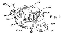
次に図面、特に図1〜図6をより詳細に参照すると、例示的なダンパー組立体100が示されている。ダンパー組立体100は、ダンパー102と、ブラケット106およびダンパーギア108を含む駆動組立体104とを含む。
Turning now to the drawings, and more particularly to FIGS. 1-6, an
ダンパー102は、外部ハウジング110を有する粘性回転ギアダンパーであり、例えば複数の部品を超音波溶接によって互いに結合して形成することができる。図示する例示的な実施形態において、ハウジング110は、外殻部112とそこに取付けられたカバー部114とを含む。外殻部112およびカバー部114は、完成した組立体において粘性減衰流体で充填される内部空間116を共に画成する。外殻部112は、その外周に歯またはリブ118を形成し、例示的実施形態において、該歯は、ダンパー102の一端で外殻部110を包囲する。歯118は、外殻部112に対して固定された要素で、外殻部112に一体形成することができる。更に、ダンパー102は、内部空間116内で回転可能であり、また孔124からカバー部114の外に延出する軸122を有したローター120を含む。軸122の平坦な末端部126は、ダンパーギア108に係合するように構成され、軸122が回転するとダンパーギア108が直接軸122と共に回転する。
The
当業者に公知であるように、粘性ダンパーは、封入空間内で減衰流体の動きをローターの回転に対して方向付けるためのバッフルおよび様々な種類の制限体(restrictions)を含み、ローターの回転を制御すると共に減衰作用を提供する。その結果、ローターに連結された外部ギアの回転が制御され、その制御された回転を、ローターに連結された外部ギアと、群衆コントロール装置の巻取スプールといった動作を制御すべき装置に設けられたギアとの間のギア連結を介して伝達することができる。 As known to those skilled in the art, a viscous damper includes a baffle and various types of restrictions to direct the movement of damping fluid within the enclosed space relative to the rotation of the rotor, and to rotate the rotor. Provides control and damping action. As a result, the rotation of the external gear connected to the rotor is controlled, and the controlled rotation is provided in the external gear connected to the rotor and the device to control the operation such as the winding spool of the crowd control device. It can be transmitted via a gear connection with the gear.
ブラケット106は、本体130と、本体130の互いに正対する側面から突出する取付脚部132、134とを含む。図示する例示的実施形態において、各取付脚部132、134は、装置にブラケット106を取付けるための留め具140、142(図7参照)を受承する孔136、138を夫々有している。図示する例示的実施形態において、留め具140、142はネジ型の留め具である。その他の種類の取付方法も可能であり、限定のためではなく例として挙げると、ネジ以外の種類の留め具を用いた方法や、独立した留め具を用いないで孔に受承される脚部にスナップ留め機構等を設ける方法や、装置内にブラケットを固定するための締め具、押さえ具または接着剤を用いた取付方法も可能であると解されるべきである。
The
一方の脚部132の内側には、外殻部110に設けられた歯またはリブ118と係合する歯または歯状部144が形成されている。本体130には中央開口部146が形成されており、該中央開口部にダンパー軸122が貫通、延設されている。中央開口部146は、同開口部146の縁に沿って上方に延びる隆起部またはリム部148が延在するように本体130に形成される。1または複数の可撓性バー150、152が、本体130において中央開口部146の外方両側に形成される。例示的実施形態では二つの上記可撓性バー150、152が示され、可撓性バー150、152は、中央開口部146の各側に夫々一つずつ設けられる。図示する例示的実施形態における可撓性バー150、152は、夫々一対の湾曲スロット154、156および158、160の間に夫々形成される弓状体である。
A tooth or tooth-
ブラケット106は、ハウジング110とダンパーギア108の間から夫々逆方向に付勢力を付与するように構成、組付および適合される。そのため、脚部132、134の寸法は、ダンパー組立体100が組み付けられたときにブラケット106がハウジング110に対して下向きの締付力を付与するように調節される。弓状可撓性バー150、152は、脚部132、134が定位置に固定されるとき、本体130の半径方向最外側部分162(図3参照)が下方に引っ張られることでカバー部114の上面に対し付勢するように配置される。同時に、本体130の半径方向最内側部分164は、カバー部114とダンパーギア108の下面との間で締め付けられる。またブラケット106は、ブラケット106を装置内に設置するための1または複数の突起部166その他の機構を含んでもよい。
The
ダンパーギア108は、ローター軸122上にスナップ嵌合により連結される。このスナップ嵌合による連結は、スナップ嵌合に先立って、ギアがリム部148に当接して押し下げられ、それと同時に最内側部分164がダンパーハウジング110のカバー部114に対して押圧されるように構成される。そのため、ギアがローターのポストにスナップ嵌合されると、ダンパーの頂部とポスト上のギアの間に固有の付勢力が生じる。可撓性バー150、152と、外側部分162および内側部分164とを含むブラケットは、可撓性バーがダンパーおよびギアに対して加える力によって、ギアとダンパーとの間の緊密または好適な連結を保証する。上記力は、作動中にダンパー組立体が所望通りに移動して、歯118を歯144に係合および歯144から係合解除するのを妨げるほど強力ではない。しかしながら、ブラケット106の付勢力は、減衰中の歯の係合および自由回転中の歯の係合解除を確実にするのに役立つ。
The
ダンパー組立体100は、ハウジング110およびブラケット106に設けられた協働係合構造、すなわち、歯118および歯144、の係合および係合解除を利用して、(歯係合時の)減衰効果と、(歯係合解除時の)減衰効果を生じない自由回転とを交互に提供する。歯が係合解除されているとき、ダンパーハウジング110は、ブラケット106に対して移動可能である。そのため、ダンパーハウジング110とローター120との間に相対回転は生じない。反対に、歯が係合されているとき、ダンパーハウジング110は、ブラケット106に対して固定保持される。従って、ダンパーハウジング110とローター120との間に相対回転が起こり、その結果、減衰効果がダンパーギア108を介して伝達される。
The
可撓性バー150、152は、歯係合時(図5参照)の減衰状態および歯の係合解除時(図6参照)の自由回転状態のどちらにおいても、ダンパー102およびブラケット106を定位置に保持する役目を果たす。ブラケット106がダンパー102およびダンパーギア108に対して加える抵抗または所望の力がなければ、特に、ポスト上に設けられた群衆コントロール装置が倒されたりしてダンパーの垂直方向が変わった場合に、歯は所望通りに係合または係合解除することができない。自由回転すなわち非減衰状態が所望される場合、可撓性バーは、ダンパーおよびギアと協働して歯間の係合解除状態を確保する。抵抗または所望の力がなければ、歯は、不都合に部分的に係合することがあり、その結果、装置内のダンパーの動作から望ましくない動作音(ratcheting noise)が生じる。ブラケットは、ブラケットおよびダンパーに係合された装置に対するダンパーの適正な配置および動作を保証する力を提供する。
The
図7は、ダンパー組立体100を含む動作被減衰装置200を示す。限定のためではなく例として示すと、被減衰装置200は、ロープ、ストラップ、ウェブ等のための群衆コントロールリール機構とすることができる。動作被減衰装置200は、外側本体202と固定エンドプレート204とを含む。装置200の可動部品は、エンドプレート204を貫通して延びる回転自在な軸206を含む。ギア208は、軸206に駆動可能に配置され、ダンパーギア108と作動的に係合される。それにより、ダンパー組立体100の減衰効果が、ダンパーギア108と装置ギア208の間のギア接続を介して装置200の可動部品の動作に伝達される。
FIG. 7 shows an operational damped
図8、9は、別の動作被減衰装置を示し、該装置は、自立式ポスト上部や同ポスト内部への取付け、または、壁やその他の構造物に据え付けられたハウジング内への取付けに適した群衆コントロール装置210である。群衆コントロール装置210は、スプール214および同スプールに巻回されたウェブ、ロープ、ベルトまたはストラップ216を有するリール組立体212を含む。ストラップ216の末端に設けた固定具218を、別の構造物や同様に構成される群衆コントロール装置のポストに固定することも、または、当業者がすぐに分かるような、該固定具のために製造された単純な受容ブラケットに固定することも可能である。リール組立体212は、ヘッド部220と、ベース部222と、ヘッド部とベース部の間に配置されるピラー部224とを含む。キャッププレート226は、スプール214に連結されてスプールと共に回転する。既述したようなダンパー組立体100が、キャッププレート226上に取付けられてプレート226およびスプール214と共に移動する。内部に歯を設けたリングギア228は、ヘッド部220に固定されて動かない。ダンパーギア108はリングギア228と係合しているため、スプール214、プレート226およびダンパー組立体100が動くと、ダンパーギア108は、リングギア228の歯と係合してリングギア228の内側で回転する。その結果、ダンパー組立体100の減衰作用が、ダンパーギア108とリングギア228との駆動関係およびダンパー組立体のスプールへの連結を介して、スプール214の回転へと伝達される。ダンパー組立体100は、滑らかで安定した速度および加速を向上促進するため、巻取中のストラップの捕捉や制止によって巻取りが妨害されたとしても、不規則な暴れを減じて巻取りを行うことができる。ダンパーは、速度および加速における不安定さを緩和する。一方向ダンパー組立体を設ける場合、減衰制御を巻取機能のみに限定して、繰出しに関してはダンパーの影響を受けないようにすることができる。
FIGS. 8 and 9 show another motion-damped device suitable for mounting on a self-supporting post, within the post, or within a housing mounted on a wall or other structure.
更に他の様式のダンパー係合構成を用いてダンパー組立体を動作被減衰装置に連結することができることも理解すべきである。装置側の協働ギアおよびダンパーギアのうちの一方が、群衆コントロール装置のヘッド部やその他の部分といった装置の不動部分に対して固定され、協働ギアおよびダンパーギアのうちの他方が、群衆コントロール装置に設けられたリール組立体のスプールおよび/または他の回転部品といった装置の可動部分と共に回転するように取付けられる、他のギア構成を用いることができる。その結果、ダンパーの制御特性が、群衆コントロール装置のスプールの巻上機構といった装置の可動部分に伝達される。 It should also be understood that other types of damper engagement configurations can be used to couple the damper assembly to the motion dampened device. One of the cooperating gear and damper gear on the device side is fixed to a stationary part of the device such as the head and other parts of the crowd control device, and the other of the cooperating gear and damper gear is the crowd control Other gear configurations can be used that are mounted for rotation with the movable part of the device, such as a spool and / or other rotating parts of a reel assembly provided in the device. As a result, the control characteristics of the damper are transmitted to a movable part of the device, such as a spool winding mechanism of the crowd control device.
ダンパー組立体の群衆コントロール装置における用途や使用に特化して図示し説明してきたが、家具等の可動部品を有する多種多様な他の構造体および装置、種々の自動車用途、並びに、その他多くの種類の装置において、該ダンパー組立体を使用できることが当業者に容易に理解されよう。 Although illustrated and described specifically for use and use in damper assembly crowd control devices, a wide variety of other structures and devices with moving parts such as furniture, various automotive applications, and many other types One skilled in the art will readily appreciate that the damper assembly can be used in the present apparatus.
上記形態の変形および修正は、本発明の範囲内に含まれる。本明細書において開示および定義される発明は、本文および/または図面に記載され、或いは、これらにより明らかな複数の特徴を組合せた他の発明の全てに及ぶことが理解される。これらの異なる組合せの全ては、本発明の様々な別の形態を構成する。本明細書に記載される実施形態は、本発明を実施するための既知の最良モードを説明しており、当業者による本発明の使用を可能にする。特許請求の範囲は、従来技術によって許容される範囲まで別の実施形態を含むと解釈すべきである。
本発明の様々な特徴は特許請求の範囲に記載されている。
Variations and modifications of the above forms are included within the scope of the present invention. It will be understood that the invention disclosed and defined herein extends to all other inventions described in the text and / or drawings or in combination with features apparent therefrom. All of these different combinations constitute various alternative aspects of the invention. The embodiments described herein illustrate the best mode known for practicing the present invention and enable those skilled in the art to use the present invention. The claims should be construed to include alternative embodiments to the extent permitted by the prior art.
Various features of the invention are set forth in the following claims.
100 ダンパー組立体
102 ダンパー
104 駆動組立体
106 ブラケット
108 ダンパーギア
110 ハウジング
112 外殻部
114 カバー部
116 内部空間
118 歯またはリブ
120 ローター
122 軸
122 ローター軸
124 孔
126 末端部
130 本体
132 脚部
134 脚部
140 留め具
142 留め具
144 歯または歯状部
146 中央開口部
148 隆起部またはリム部
150 可撓性バー
152 可撓性バー
154 湾曲スロット
156 湾曲スロット
158 湾曲スロット
160 湾曲スロット
162 半径方向最外側部分
164 半径方向最内側部分
166 突起部
200 動作被減衰装置
202 外側本体
204 固定エンドプレート
206 軸
208 ギア
210 群衆コントロール装置
212 リール組立体
214 スプール
216 ストラップ
218 固定具
220 ヘッド部
222 ベース部
224 ピラー部
226 キャッププレート
228 リングギア
DESCRIPTION OF
Claims (19)
装置の作動中に動く可動部品と、
装置の作動中に動かない静止部品と、
前記可動部品および前記静止部品のうちの一方に連結される装置ギアと、
前記可動部品および前記静止部品のうちの他方に連結されるダンパー組立体とを具備し、
前記ダンパー組立体は、
ローターとローター軸とを有するダンパーと、
前記ローター軸に作動可能に配置され、前記装置ギアと作動的に係合するダンパーギアと、
前記ダンパーの周囲に取付けられた固定ブラケットであって、前記ダンパーおよび前記ダンパーギアに対して夫々逆方向の力を前記ローター軸の中心軸線に平行に加える部分を含む固定ブラケットとを具備する動作被減衰装置。 In operation damped device,
Moving parts that move during operation of the device;
Stationary parts that do not move during operation of the device;
A device gear coupled to one of the movable part and the stationary part;
A damper assembly coupled to the other of the movable part and the stationary part,
The damper assembly is
A damper having a rotor and a rotor shaft;
A damper gear operably disposed on the rotor shaft and operatively engaged with the device gear;
An operating bracket comprising a fixing bracket attached around the damper, the fixing bracket including a portion that applies a force in the opposite direction to the damper and the damper gear in parallel to the central axis of the rotor shaft. Damping device.
ハウジングと、前記ハウジング内に設けたローターと、前記ハウジングから外側に延出するローター軸とを含むダンパーと、A damper including a housing, a rotor provided in the housing, and a rotor shaft extending outward from the housing;
前記ローター軸の末端に配置されたダンパーギアと、A damper gear disposed at the end of the rotor shaft;
前記ダンパーと前記ダンパーギアの間に位置される本体と、前記ダンパーの外側に配置され、装置内に前記ダンパー組立体に取付けるための機構を形成する脚部とを有するダンパーブラケットと、A damper bracket having a body positioned between the damper and the damper gear, and a leg disposed outside the damper and forming a mechanism for attachment to the damper assembly in the apparatus;
前記ダンパーハウジングおよび前記ダンパーブラケットに設けられた協働係合構造であって、前記ダンパーハウジングを選択的に前記ダンパーブラケットに係合または同ダンパーブラケットから係合解除することにより両者の間の相対回転を可能または不能にする協働係合構造とを具備し、A cooperative engagement structure provided on the damper housing and the damper bracket, wherein the damper housing is selectively engaged with or disengaged from the damper bracket to relatively rotate between them. A cooperating engagement structure that enables or disables
前記ダンパーブラケットは、前記ダンパーハウジング、および、同ダンパーハウジングに対向する前記ダンパーギアの側面に対して作用する付勢構造を有するダンパー組立体。The damper bracket includes a damper assembly and a biasing structure that acts on a side surface of the damper gear that faces the damper housing and the damper housing.
本体と脚部とを有するダンパーブラケットと、A damper bracket having a body and a leg;
前記ダンパーブラケット本体の第1の側において前記脚部の間に配置されるダンパーと、A damper disposed between the legs on the first side of the damper bracket body;
前記ダンパーに設けられたローターであって、同ローターから外側に延出して前記ダンパーブラケット本体を貫通する軸を有するローターと、A rotor provided in the damper, the rotor having an axis extending outward from the rotor and penetrating the damper bracket body;
前記ダンパーブラケット本体の第2の側において前記ローター軸に配置されるダンパーギアとを具備し、A damper gear disposed on the rotor shaft on the second side of the damper bracket body,
前記ダンパーブラケット本体は、前記ダンパーおよび前記ダンパーギアの間から付勢力を付与し、前記付勢力が、前記ダンパーおよび前記ダンパーギアの各々に対して加えられるダンパー組立体。The damper bracket main body applies a biasing force from between the damper and the damper gear, and the biasing force is applied to each of the damper and the damper gear.
Applications Claiming Priority (5)
| Application Number | Priority Date | Filing Date | Title |
|---|---|---|---|
| US15449009P | 2009-02-23 | 2009-02-23 | |
| US61/154,490 | 2009-02-23 | ||
| US22174809P | 2009-06-30 | 2009-06-30 | |
| US61/221,748 | 2009-06-30 | ||
| PCT/US2010/021574 WO2010096229A1 (en) | 2009-02-23 | 2010-01-21 | Damper assembly and device utilizing the same |
Publications (3)
| Publication Number | Publication Date |
|---|---|
| JP2012518759A JP2012518759A (en) | 2012-08-16 |
| JP2012518759A5 JP2012518759A5 (en) | 2013-03-07 |
| JP5731410B2 true JP5731410B2 (en) | 2015-06-10 |
Family
ID=42634174
Family Applications (1)
| Application Number | Title | Priority Date | Filing Date |
|---|---|---|---|
| JP2011551083A Expired - Fee Related JP5731410B2 (en) | 2009-02-23 | 2010-01-21 | Damper assembly and apparatus using the assembly |
Country Status (5)
| Country | Link |
|---|---|
| US (1) | US9261158B2 (en) |
| EP (1) | EP2398678B1 (en) |
| JP (1) | JP5731410B2 (en) |
| CN (1) | CN102317125B (en) |
| WO (1) | WO2010096229A1 (en) |
Families Citing this family (9)
| Publication number | Priority date | Publication date | Assignee | Title |
|---|---|---|---|---|
| US20110120823A1 (en) * | 2009-11-20 | 2011-05-26 | Charles Hansen | Retracta Belt Brake System |
| US9273754B2 (en) * | 2012-02-27 | 2016-03-01 | Ford Global Technologies, Llc | Non-uniform axisymmetric driveline/axle damper |
| JP6570337B2 (en) * | 2014-07-17 | 2019-09-04 | キヤノン株式会社 | Image forming apparatus and damper apparatus |
| KR102211462B1 (en) * | 2014-09-04 | 2021-02-03 | 현대모비스 주식회사 | Structure of damper for glove box |
| US10718145B2 (en) * | 2016-12-14 | 2020-07-21 | Ford Global Technologies, Llc | Viscous damper with integral spring |
| CN106920324B (en) * | 2017-03-09 | 2023-03-28 | 深圳怡化电脑股份有限公司 | Transmission device, banknote door structure and automatic teller machine |
| CN109972937B (en) * | 2017-12-27 | 2022-05-10 | 伊利诺斯工具制品有限公司 | Door lock assembly for oil filling or charging port |
| USD894719S1 (en) * | 2018-07-19 | 2020-09-01 | Adam Mills | Multi-position wall mounted barrier |
| DE102020117520A1 (en) * | 2020-07-02 | 2022-01-05 | Illinois Tool Works Inc. | DEVICE AND METHOD FOR NOISE REDUCTION FROM A LINEAR DAMPER |
Family Cites Families (21)
| Publication number | Priority date | Publication date | Assignee | Title |
|---|---|---|---|---|
| JPS5010501A (en) | 1973-05-25 | 1975-02-03 | ||
| JPS5010501U (en) * | 1973-05-25 | 1975-02-03 | ||
| US4088281A (en) * | 1976-10-13 | 1978-05-09 | American Safety Equipment Corporation | Dual tension single spring retractor |
| JPS56124532A (en) | 1980-03-07 | 1981-09-30 | Takata Kk | Seat belt retractor with memory |
| US4576252A (en) * | 1983-04-15 | 1986-03-18 | Nifco Inc. | Rotation damper |
| JPS6079032U (en) * | 1983-11-07 | 1985-06-01 | 株式会社ニフコ | oil damper |
| US4527675A (en) * | 1984-04-19 | 1985-07-09 | Nifco Inc. | Oil type damper |
| JPS6124850A (en) * | 1984-07-16 | 1986-02-03 | Nifco Inc | One way damper |
| JPH023656Y2 (en) | 1984-10-23 | 1990-01-29 | ||
| JP4467688B2 (en) * | 1999-01-19 | 2010-05-26 | タカタ株式会社 | Seat belt retractor |
| GB9903896D0 (en) * | 1999-02-19 | 1999-04-14 | Tensator Ltd | A post for a queue management system |
| US6298960B1 (en) * | 2000-05-30 | 2001-10-09 | Illinois Tool Works Inc. | Small viscous precision damper |
| US6637567B2 (en) * | 2001-11-29 | 2003-10-28 | Illinois Tool Works Inc. | Free run clutch apparatus |
| DE10210917C1 (en) * | 2002-03-13 | 2003-11-13 | Itw Automotive Prod Gmbh & Co | Braking device with freewheel |
| US7152718B2 (en) * | 2002-04-16 | 2006-12-26 | Illinois Tool Works Inc | Damper |
| US6866588B2 (en) * | 2002-06-11 | 2005-03-15 | Illinois Tool Works Inc. | One-way damper |
| US6910557B2 (en) * | 2003-01-29 | 2005-06-28 | Illinois Tool Works Inc. | Slide damper with spring assist |
| US7350629B2 (en) * | 2004-11-18 | 2008-04-01 | Illinois Tool Works Inc. | Floating damper |
| US20070108676A1 (en) * | 2005-11-14 | 2007-05-17 | Zeilenga Chad K | Viscous strand damper assembly |
| US8079450B2 (en) | 2005-11-14 | 2011-12-20 | Illinois Tool Works Inc. | Viscous strand damper assembly |
| US20110120823A1 (en) | 2009-11-20 | 2011-05-26 | Charles Hansen | Retracta Belt Brake System |
-
2010
- 2010-01-21 US US13/202,178 patent/US9261158B2/en not_active Expired - Fee Related
- 2010-01-21 JP JP2011551083A patent/JP5731410B2/en not_active Expired - Fee Related
- 2010-01-21 EP EP10744100.8A patent/EP2398678B1/en not_active Not-in-force
- 2010-01-21 WO PCT/US2010/021574 patent/WO2010096229A1/en active Application Filing
- 2010-01-21 CN CN201080008003.XA patent/CN102317125B/en not_active Expired - Fee Related
Also Published As
| Publication number | Publication date |
|---|---|
| US9261158B2 (en) | 2016-02-16 |
| US20110296938A1 (en) | 2011-12-08 |
| WO2010096229A1 (en) | 2010-08-26 |
| CN102317125A (en) | 2012-01-11 |
| EP2398678A1 (en) | 2011-12-28 |
| CN102317125B (en) | 2015-07-01 |
| JP2012518759A (en) | 2012-08-16 |
| EP2398678B1 (en) | 2018-07-18 |
| EP2398678A4 (en) | 2014-09-03 |
Similar Documents
| Publication | Publication Date | Title |
|---|---|---|
| JP5731410B2 (en) | Damper assembly and apparatus using the assembly | |
| US4550470A (en) | Combined rotary damper device including a stored energy mechanism and braking mechanism | |
| US5794878A (en) | Device for prevention of slap-back lock of inertia reel | |
| JP5798627B2 (en) | Tensioner with telescopic spring with asymmetric radial friction damper action | |
| JP2013536929A (en) | Tensioner with extension spring for asymmetric radial friction damper action | |
| US9212731B2 (en) | Tensioner with multiple nested torsion springs | |
| US20050211816A1 (en) | Webbing take-up device | |
| US7152718B2 (en) | Damper | |
| US20150031484A1 (en) | Tensioner with single torsion spring having multiple nested windings | |
| KR101805762B1 (en) | Door checker for vehicle | |
| JPH05305856A (en) | Seat belt retractor | |
| KR200487831Y1 (en) | The roll screen for a reduction module | |
| KR100471682B1 (en) | hinge using inetia | |
| JPH1026163A (en) | Mounting device for absorbing impact on apparatus | |
| JP2014020179A (en) | Rotation control device | |
| JP3818953B2 (en) | Sheet winding device | |
| JP4973567B2 (en) | Door position control device | |
| FR2620988A1 (en) | TENSIONING DEVICE FOR A SEAT BELT TENSIONER | |
| JPH0517462Y2 (en) | ||
| JP2529303Y2 (en) | Rotary damper device | |
| JP3246766B2 (en) | Rotary damper | |
| JP4020840B2 (en) | Sliding door braking device | |
| JP3464641B2 (en) | Automatic winding screen device | |
| JP4005718B2 (en) | Damper device | |
| KR200281647Y1 (en) | hinge using inertia |
Legal Events
| Date | Code | Title | Description |
|---|---|---|---|
| A521 | Request for written amendment filed |
Free format text: JAPANESE INTERMEDIATE CODE: A523 Effective date: 20130121 |
|
| A621 | Written request for application examination |
Free format text: JAPANESE INTERMEDIATE CODE: A621 Effective date: 20130121 |
|
| A977 | Report on retrieval |
Free format text: JAPANESE INTERMEDIATE CODE: A971007 Effective date: 20131127 |
|
| A131 | Notification of reasons for refusal |
Free format text: JAPANESE INTERMEDIATE CODE: A131 Effective date: 20140107 |
|
| A521 | Request for written amendment filed |
Free format text: JAPANESE INTERMEDIATE CODE: A523 Effective date: 20140407 |
|
| A131 | Notification of reasons for refusal |
Free format text: JAPANESE INTERMEDIATE CODE: A131 Effective date: 20141007 |
|
| A521 | Request for written amendment filed |
Free format text: JAPANESE INTERMEDIATE CODE: A523 Effective date: 20141121 |
|
| TRDD | Decision of grant or rejection written | ||
| A01 | Written decision to grant a patent or to grant a registration (utility model) |
Free format text: JAPANESE INTERMEDIATE CODE: A01 Effective date: 20150310 |
|
| A61 | First payment of annual fees (during grant procedure) |
Free format text: JAPANESE INTERMEDIATE CODE: A61 Effective date: 20150409 |
|
| R150 | Certificate of patent or registration of utility model |
Ref document number: 5731410 Country of ref document: JP Free format text: JAPANESE INTERMEDIATE CODE: R150 |
|
| R250 | Receipt of annual fees |
Free format text: JAPANESE INTERMEDIATE CODE: R250 |
|
| R250 | Receipt of annual fees |
Free format text: JAPANESE INTERMEDIATE CODE: R250 |
|
| R250 | Receipt of annual fees |
Free format text: JAPANESE INTERMEDIATE CODE: R250 |
|
| R250 | Receipt of annual fees |
Free format text: JAPANESE INTERMEDIATE CODE: R250 |
|
| LAPS | Cancellation because of no payment of annual fees |