JP5726378B2 - Method for estimating the pose of an object - Google Patents
Method for estimating the pose of an object Download PDFInfo
- Publication number
- JP5726378B2 JP5726378B2 JP2014514266A JP2014514266A JP5726378B2 JP 5726378 B2 JP5726378 B2 JP 5726378B2 JP 2014514266 A JP2014514266 A JP 2014514266A JP 2014514266 A JP2014514266 A JP 2014514266A JP 5726378 B2 JP5726378 B2 JP 5726378B2
- Authority
- JP
- Japan
- Prior art keywords
- boundary
- pair
- feature
- points
- model
- Prior art date
- Legal status (The legal status is an assumption and is not a legal conclusion. Google has not performed a legal analysis and makes no representation as to the accuracy of the status listed.)
- Active
Links
- 238000000034 method Methods 0.000 title claims description 43
- 230000009466 transformation Effects 0.000 claims description 13
- 239000013598 vector Substances 0.000 claims description 11
- 230000008569 process Effects 0.000 claims description 8
- 238000000844 transformation Methods 0.000 claims description 4
- 230000036544 posture Effects 0.000 description 39
- 238000010586 diagram Methods 0.000 description 9
- 238000013519 translation Methods 0.000 description 7
- 230000014616 translation Effects 0.000 description 7
- 238000005070 sampling Methods 0.000 description 4
- 230000001154 acute effect Effects 0.000 description 3
- 238000013459 approach Methods 0.000 description 3
- 238000006243 chemical reaction Methods 0.000 description 3
- 238000005259 measurement Methods 0.000 description 3
- 238000013139 quantization Methods 0.000 description 3
- 238000012935 Averaging Methods 0.000 description 2
- 238000001514 detection method Methods 0.000 description 2
- 238000009826 distribution Methods 0.000 description 2
- 230000006870 function Effects 0.000 description 2
- 238000007781 pre-processing Methods 0.000 description 2
- 230000002776 aggregation Effects 0.000 description 1
- 238000004220 aggregation Methods 0.000 description 1
- 230000009286 beneficial effect Effects 0.000 description 1
- 238000003708 edge detection Methods 0.000 description 1
- 238000005286 illumination Methods 0.000 description 1
- 230000006872 improvement Effects 0.000 description 1
- 239000011159 matrix material Substances 0.000 description 1
- 239000002184 metal Substances 0.000 description 1
- 239000002991 molded plastic Substances 0.000 description 1
- 230000000135 prohibitive effect Effects 0.000 description 1
- 238000007637 random forest analysis Methods 0.000 description 1
- 238000009877 rendering Methods 0.000 description 1
- 238000012360 testing method Methods 0.000 description 1
- 230000036962 time dependent Effects 0.000 description 1
- 230000001131 transforming effect Effects 0.000 description 1
- 238000012795 verification Methods 0.000 description 1
Images


Classifications
-
- G—PHYSICS
- G06—COMPUTING; CALCULATING OR COUNTING
- G06T—IMAGE DATA PROCESSING OR GENERATION, IN GENERAL
- G06T7/00—Image analysis
- G06T7/70—Determining position or orientation of objects or cameras
- G06T7/73—Determining position or orientation of objects or cameras using feature-based methods
- G06T7/75—Determining position or orientation of objects or cameras using feature-based methods involving models
-
- G—PHYSICS
- G06—COMPUTING; CALCULATING OR COUNTING
- G06T—IMAGE DATA PROCESSING OR GENERATION, IN GENERAL
- G06T7/00—Image analysis
- G06T7/50—Depth or shape recovery
- G06T7/521—Depth or shape recovery from laser ranging, e.g. using interferometry; from the projection of structured light
-
- G—PHYSICS
- G06—COMPUTING; CALCULATING OR COUNTING
- G06T—IMAGE DATA PROCESSING OR GENERATION, IN GENERAL
- G06T2207/00—Indexing scheme for image analysis or image enhancement
- G06T2207/30—Subject of image; Context of image processing
- G06T2207/30108—Industrial image inspection
-
- G—PHYSICS
- G06—COMPUTING; CALCULATING OR COUNTING
- G06T—IMAGE DATA PROCESSING OR GENERATION, IN GENERAL
- G06T2207/00—Indexing scheme for image analysis or image enhancement
- G06T2207/30—Subject of image; Context of image processing
- G06T2207/30108—Industrial image inspection
- G06T2207/30164—Workpiece; Machine component
Description
本発明は、概して、3D物体の姿勢を推定することに関し、より具体的には、3Dセンサによって取得されたデータから姿勢を推定することに関する。 The present invention relates generally to estimating the pose of a 3D object, and more specifically to estimating the pose from data acquired by a 3D sensor.
物体の姿勢には、6自由度(6−DoF)、すなわち、3D並進および3D回転がある。姿勢推定の問題は、基準座標系、通常、センサの座標系に対する物体の姿勢を見出すことを意味する。姿勢は、例えば、3Dモデルを用いた、2D画像、3Dポイントクラウドなどのセンサからの測定値を使用して取得することができる。姿勢推定は、容器の拾上げ、把持、位置測定、自律的ナビゲーションおよび3D再構成など、多くのロボット工学応用において主な役割を果たす。 There are 6 degrees of freedom (6-DoF) in the posture of the object, ie 3D translation and 3D rotation. The problem of posture estimation means finding the posture of an object with respect to a reference coordinate system, usually a sensor coordinate system. The posture can be acquired using, for example, a measurement value from a sensor such as a 2D image or a 3D point cloud using a 3D model. Posture estimation plays a major role in many robotics applications such as container picking, grasping, position measurement, autonomous navigation and 3D reconstruction.
最近まで、姿勢推定は主に2D画像を使用して行われたが、その理由は、カメラの費用効率が高く、高速画像取得が可能であるためである。2D画像に関する主な問題は、2D特徴と、それらに対応するモデルの3D特徴とを一致させることにある。このことは、カメラの様々な照明条件や異なる視点により、画像空間における回転およびスケールの変化が生じるため、難易度が高いものとなる。その上、物体のいくつかの見方は、理論的に、曖昧な姿勢につながる恐れがある。入力画像と画像のデータベースとの対応を決定するため、いくつかの不変特徴記述子が知られており、同記述子では、2Dキーポイントを3D座標と一致させる。 Until recently, pose estimation was mainly performed using 2D images, because the camera is cost-effective and allows high-speed image acquisition. The main problem with 2D images is to match 2D features with the corresponding 3D features of the model. This is highly difficult because rotation and scale changes in the image space occur due to various illumination conditions of the camera and different viewpoints. Moreover, some views of objects can theoretically lead to ambiguous postures. In order to determine the correspondence between the input image and the database of images, several invariant feature descriptors are known, which match 2D keypoints with 3D coordinates.
多くの工業用部品は、例えば、機械加工された金属部品または成形されたプラスチック部品など、構造が曖昧なもの(textureless)である。したがって、画像の観察可能なエッジに大幅に依存しなければならない。物体の境界が使用される場合、物体の一連のエッジテンプレートは、前提として知られる場合が多く、テンプレートは、クエリエッジマップ(query edge map)において探索される。エッジの向きまたは階層表現を組み込むいくつかの変形形態が知られている。強度ベースのエッジ検出は、あまりにも多くのエッジ画素を生じさせる場合が多く、その場合、ほんのわずかなエッジ画素のみが深度不連続に由来する有効エッジである。マルチフラッシュカメラを使用することで、複数のフラッシュ方向から影を投影することによって深度エッジを直接推定することができる。 Many industrial parts are textureless, such as, for example, machined metal parts or molded plastic parts. Therefore, it must depend heavily on the observable edges of the image. When object boundaries are used, a sequence of object edge templates is often known as a premise, and the templates are searched in a query edge map. Several variants are known that incorporate edge orientations or hierarchical representations. Intensity-based edge detection often results in too many edge pixels, in which case only a few edge pixels are valid edges derived from depth discontinuities. By using a multi-flash camera, depth edges can be estimated directly by projecting shadows from multiple flash directions.
一般に、3Dセンサで得られる3Dデータは、2Dデータとは対照的に、はるかに少ない変形形態を有する。主な課題は、センサ雑音、オクルージョンおよびクラッタの存在下で対応問題の解を求めることである。対応問題は、データの特徴とモデルの特徴との1対1の一致を見出すことを意味する。特徴は、通常、物体のサイズや形状を特徴付けるように構成される。表面ポイントおよび法線の分布を使用するいくつかの3D特徴記述子や、一致手順が知られている。それらの記述子は、一般に、剛体変換に対して不変であるが、雑音やオクルージョンに敏感である。その上、それらの特徴は、高密度のポイントクラウドを必要とし、高密度のポイントクラウドは、利用可能でない場合がある。 In general, 3D data obtained with a 3D sensor has much fewer variations as opposed to 2D data. The main challenge is to find a solution to the corresponding problem in the presence of sensor noise, occlusion and clutter. The correspondence problem means finding a one-to-one match between the data features and the model features. The features are usually configured to characterize the size and shape of the object. Several 3D feature descriptors using surface point and normal distributions and matching procedures are known. These descriptors are generally invariant to rigid transformations, but are sensitive to noise and occlusion. Moreover, those features require a high density point cloud, which may not be available.
姿勢推定は、センサ3Dデータとモデルとの様々な種類の対応、すなわち、3ポイント対応、2線対応および3つ以上の平面に対する6ポイントで実行可能である。通常、それらの対応は、姿勢を決定するためのランダムサンプルコンセンサス(RANSAC:RANdom SAmple Consensus)などの仮説検証フレームワークで使用される。あるいは、姿勢は、ハフ投票方式またはパラメータ空間でのクラスタリングのいずれかを使用することによって、仮定の姿勢分布のモードから検索することができる。それらの手法は、画像も他の事前情報もない状態で、3Dセンサデータのみが利用可能である場合、2つの問題に悩まされる。ポイント、線および平面は、それほど個別に区別可能なものではなく、組み合わせて一致させることができ、モデルに対して何の事前処理も行うことなく、高速演算を達成することは難しい。 Posture estimation can be performed with various types of correspondence between the sensor 3D data and the model, that is, 3 points, 2 lines, and 6 points for 3 or more planes. Typically, these correspondences are used in hypothesis verification frameworks such as Random Sample Consensus (RANSAC) to determine pose. Alternatively, the pose can be retrieved from the assumed pose distribution mode by using either a Hough voting scheme or clustering in the parameter space. These approaches suffer from two problems when only 3D sensor data is available with no images or other prior information. The points, lines and planes are not so individually distinguishable and can be combined and matched and it is difficult to achieve high speed computation without any pre-processing on the model.
対特徴は、物体の表面上の2つの方向付けされたポイント間の距離および相対的な向きによって定義することができる。物体は、一連の方向付けされたポイント対特徴によって表され、それらの対特徴は、高速検索のためにハッシュ表Hに格納される。ランダムな2つのポイントは、センサデータからサンプリングされ、そのような各対は、特定の姿勢に投票する。必要な姿勢は、最大投票数を有するものに相当する。画素とオフセット画素との深度差からなる、より簡単な対特徴は、ランダムフォレスト集合分類子を用いる人間の姿勢推定に使用される。 Pair features can be defined by the distance and relative orientation between two oriented points on the surface of the object. Objects are represented by a series of directed point-pair features, which are stored in a hash table H for fast retrieval. Two random points are sampled from the sensor data, and each such pair votes for a particular posture. The required posture corresponds to the one having the maximum number of votes. A simpler pairing feature consisting of depth differences between pixels and offset pixels is used for human pose estimation using a random forest set classifier.
本発明の実施形態は、3Dセンサによって取得されたデータから物体の姿勢を推定するための投票ベースの方法を提供する。先行技術で使用される方向付けされた表面ポイント(法線を有する、物体の表面上のポイント)は、かなりの曲率変化がある物体に対して区別可能なものであり、それらの表面ポイントは、平面状の多くの工業用の物体および現実世界の物体に対して十分にコンパクトなものでも、区別可能なものでもない。 Embodiments of the present invention provide a voting-based method for estimating the pose of an object from data acquired by a 3D sensor. Oriented surface points (points on the surface of an object that have normals) used in the prior art are distinguishable for objects with significant curvature changes, and these surface points are It is neither sufficiently compact nor distinguishable from many planar industrial and real world objects.
境界から情報を得るため、2D登録ではエッジが重要な役割を果たす一方で、3Dでは深度不連続が極めて重要である。実施形態は、この境界情報をより良く活用する姿勢推定方法ファミリを提供する。方向付けされた表面ポイントに加えて、方向付けされた境界ポイント(方向を有する、物体の境界上のポイント)および境界線セグメントを含む、他の2つの幾何プリミティブを使用する。 Edges play an important role in 2D registration to get information from the boundaries, while depth discontinuity is very important in 3D. Embodiments provide a family of attitude estimation methods that better utilize this boundary information. In addition to the directed surface points, two other geometric primitives are used, including oriented boundary points (points on the boundary of the object with direction) and boundary segments.
慎重に選択されたプリミティブは、より多くの情報をコンパクトに符号化し、それにより、幅広いクラスの工業用部品に対してより優れた精度を提供し、さらなる高速演算を可能にする。 Carefully selected primitives encode more information in a compact manner, thereby providing better accuracy for a broad class of industrial components and enabling higher speed operations.
図1は、物体の姿勢を推定するためのシステム100を示す。システムは、グリッパ120を備えた6軸ロボットアーム110を含む。3Dセンサ130は、アーム上に配置される。グリッパは、物体の姿勢101に応じて、容器150から物体140を拾い上げる。容器は異なる物体を含み得ることに留意されたい。
FIG. 1 shows a
3Dセンサの一例は、赤外レーザによって生成される構造化された光を使用する。また、他のセンサも可能である。センサは、640×480画素の深度マップとして3D「ポイントクラウド」160を取得する。3Dセンサは、ロボットアームに対して較正され、それにより、姿勢を使用して、物体を把持することおよび拾い上げることが可能になる。 One example of a 3D sensor uses structured light generated by an infrared laser. Other sensors are also possible. The sensor obtains a 3D “point cloud” 160 as a depth map of 640 × 480 pixels. The 3D sensor is calibrated with respect to the robot arm, which allows the object to be gripped and picked up using posture.
3Dポイントクラウドは、プロセッサ170で実行される方法によって処理される。プロセッサは、当技術分野で知られているように、メモリおよび入力/出力インターフェースを含み得る。本方法は、姿勢を決定し、物体140を拾い上げるようにアームに指示するため、決定された姿勢を、コントローラ180にフィードバックすることができる。
The 3D point cloud is processed by a method executed by the
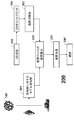
図2Aは、方法200のブロック図を示し、次の工程、すなわち、場面の3D検知210と、投票ベースの姿勢推定220と、姿勢改善230と、その姿勢に応じた物体の把持240とを含む。
FIG. 2A shows a block diagram of the
システムは、3Dセンサを使用して物体の容器をスキャンし、本方法によって決定された姿勢に従って物体を検出して、物体を拾い上げる。容器内の異なる各物体の3D CADモデルを考慮して、投票ベースの方法は、スキャンされた3Dポイントクラウド160を使用して、物体の検出および姿勢推定を実行する。この工程は、複数の粗姿勢を提供する。システムは、いくつかの最適な粗姿勢を選択し、反復最近点(ICP:iterative−closest point)手順を使用して、姿勢を個別に改善する。
The system uses a 3D sensor to scan the container of the object, detects the object according to the attitude determined by the method, and picks up the object. Considering the 3D CAD model of each different object in the container, the voting-based method uses the scanned
一般に、ICPは、2つの3Dポイントクラウド間の差を最小化する。ICPは、異なる位置で取得された複数の部分的なスキャンから完全な3Dモデルを再構成し、3D環境モデルに対してロボットの位置測定を行うために使用される場合が多い。手順は、対応するポイント間の距離の最小化に必要な変換(並進および回転)を反復修正することによって、リアルタイムで実行することができる。入力は、2つの3Dポイントクラウド、変換の初期推定および終了基準である。出力は、改善された変換である。主な工程は、最近隣基準によって対応するポイントを見出す工程、費用関数として平均二乗誤差を使用して変換パラメータを推定する工程、推定されたパラメータを使用してポイントを変換する工程、および、反復する工程を含む。 In general, ICP minimizes the difference between two 3D point clouds. ICP is often used to reconstruct a complete 3D model from multiple partial scans acquired at different locations and to perform robot position measurements on the 3D environment model. The procedure can be performed in real time by iteratively correcting the transformations (translation and rotation) necessary to minimize the distance between corresponding points. The inputs are two 3D point clouds, an initial estimate of the transformation and a termination criterion. The output is an improved conversion. The main steps are finding corresponding points by nearest neighbor criteria, estimating transformation parameters using mean square error as a cost function, transforming points using estimated parameters, and iteration The process of carrying out is included.
本発明者らのシステムのICP手順は、現在の姿勢推定を使用して物体のCADモデルをレンダリングし、レンダリングされたモデルの表面をサンプリングすることによって、モデルに対する3Dポイントクラウドを生成する。次いで、ICPは、モデルの各3Dポイントに対して、スキャンされたポイントクラウドの最も近い3Dポイントを決定し、3Dポイント対応を使用して姿勢推定を更新する。 The ICP procedure of our system generates a 3D point cloud for the model by rendering the CAD model of the object using the current pose estimate and sampling the surface of the rendered model. The ICP then determines, for each 3D point in the model, the closest 3D point in the scanned point cloud and updates the pose estimate using the 3D point correspondence.
ICPが収束した後、スキャンされたポイントクラウドの対応する3Dポイントとモデルの対応する3Dポイントとの間の平均距離として登録誤差が測定される。登録誤差は、ICPが不適正な姿勢に収束する場合、または、他の物体からのオクルージョンが原因で物体の一部が欠如する場合に高い可能性がある。したがって、登録誤差が高い場合は、本発明者らのシステムは、把持に対して推定された姿勢を使用しない。登録誤差に加えて、本発明者らのシステムは、物体を拾い上げることができるかどうかを決定するため、ロボットアームによってその姿勢の物体に到達できるかどうかもチェックする。 After the ICP converges, the registration error is measured as the average distance between the corresponding 3D point in the scanned point cloud and the corresponding 3D point in the model. Registration errors can be high if the ICP converges to an incorrect posture or if some of the object is missing due to occlusion from another object. Therefore, if the registration error is high, our system does not use the estimated posture for gripping. In addition to registration errors, our system also checks whether an object in that posture can be reached by the robot arm to determine if the object can be picked up.
座標系
本説明の目的のため、3つの座標系が使用される。センサは、センサ(カメラ)座標系Cの観点から表現される。物体のモデルは、物体座標系Oの観点から表現される。場面の物体は、世界座標系Wを使用する。センサは、一般に、現実世界の公知の位置および向きにあるため、センサ座標系Sは、世界座標系Wに対して較正することができる。
Coordinate systems For the purposes of this description, three coordinate systems are used. The sensor is expressed from the viewpoint of a sensor (camera) coordinate system C. The object model is expressed from the viewpoint of the object coordinate system O. The object in the scene uses the world coordinate system W. Since the sensor is typically in a known position and orientation in the real world, the sensor coordinate system S can be calibrated with respect to the world coordinate system W.
姿勢推定方法は、センサ座標系と物体座標系との間の変換を決定する。次いで、センサ座標系と世界座標系との関係は、場面の物体操作に使用することができる。 The posture estimation method determines the conversion between the sensor coordinate system and the object coordinate system. The relationship between the sensor coordinate system and the world coordinate system can then be used for object manipulation of the scene.
投票ベースの姿勢推定
姿勢推定のための本発明者らの特徴は、方向付けされたポイントまたは線の対に基づき、これを対特徴と呼ぶ。ある方向付けされたポイント(基準)から別のポイント(関連)まで特徴ベクトルを非対称的に構成するため、方向付けされた表面ポイントの対からなる対特徴は、S2Sで示される。同様に、方向付けされた境界ポイントの対(B2B)、線セグメントの対(L2L)および異種対(方向付けされた表面ポイントと方向付けされた境界ポイント(S2BとB2S)を含む)に基づいて、他の4つの対特徴を有する(図3A〜3Dを参照)。
Voting Based Posture Estimation Our feature for posture estimation is based on a pair of oriented points or lines, which is called a pair feature. In order to construct the feature vector asymmetrically from one directed point (reference) to another (related), the paired feature consisting of a pair of oriented surface points is denoted S2S. Similarly, based on directed boundary point pairs (B2B), line segment pairs (L2L) and heterogeneous pairs (including directed surface points and directed boundary points (S2B and B2S)) , With four other pairing features (see FIGS. 3A-3D).
ポイント対特徴記述子FS2S、FB2B、FS2BおよびFB2Sは、方向付けされたポイントの対(m,n)の相対位置f1ならびに向きf2、f3およびf4によって定義され、ポイントは、表面法線を有する表面ポイントまたは方向を有する境界ポイントのいずれかを示す。図3Dでは、線対特徴記述子FL2Lは、2つの無限線間の最小距離f1、2つの線方向間の鋭角f2および2つの線セグメント間の最大距離f3によって定義される。 The point-to-feature descriptors F S2S , F B2B , F S2B and F B2S are defined by the relative position f 1 and the orientations f 2 , f 3 and f 4 of the directed point pair (m, n) Indicates either a surface point having a surface normal or a boundary point having a direction. In FIG. 3D, the line pair feature descriptor F L2L is defined by a minimum distance f 1 between two infinite lines, an acute angle f 2 between two line directions, and a maximum distance f 3 between two line segments.
物体の姿勢を推定するため、場面やモデルから得られるような対特徴間の対応を確立することが必要とされる。対特徴から、その記述子として、様々な幾何制約を使用する。次いで、場面対特徴とモデル対特徴との対応は、それらの記述子を一致させることによって確立される。 In order to estimate the posture of an object, it is necessary to establish a correspondence between pairs of features as obtained from scenes and models. From geometric features, we use various geometric constraints as descriptors. A correspondence between the scene-pair feature and the model-pair feature is then established by matching their descriptors.
対特徴
S2S−表面対特徴:
表面対特徴S2Sは、物体の表面上の2つのポイントと、2つのポイントの法線とを使用して定義される。場面からの方向付けされたポイントおよびモデルからの対応するプリミティブを考慮して、3D姿勢は、ポイント位置およびポイントの法線を位置合わせすることによって、平面回転まで回復させることができる。回転の曖昧性を解決し、完全な6−DoF姿勢を回復させるため、少なくとも場面プリミティブとモデルプリミティブの2対間の対応が必要である。
Pair Features S2S-Surface Pair Features:
The surface pair feature S2S is defined using two points on the surface of the object and the normals of the two points. Considering the directed points from the scene and the corresponding primitives from the model, the 3D pose can be restored to planar rotation by aligning the point position and the normal of the point. In order to resolve the rotation ambiguity and restore the full 6-DoF pose, at least a correspondence between two pairs of scene primitives and model primitives is required.
{(mr,nr),(mi,ni)}は対特徴を示し、mrは物体の表面上の基準点であり、miは物体の表面上の関連点であり、nrおよびniはそれぞれに対応する法線であるものとする。この対特徴を有する関連記述子は、以下の通りであり、

したがって、記述子の第1の成分は、f1=||mi−mr||2=||d||2を表し、これは、2つの表面ポイント間のユークリッド距離である。第2の成分f2は、ベクトルdと表面法線ベクトルnrとの間の角度であり、第3の成分f3は、ベクトルdと表面法線ベクトルniとの間の角度である。最後の成分f4は、2つの法線ベクトル間の角度である。S2S特徴は、図3Aに示される。物体が広範囲の法線にまで広がれば、この特徴は、物体の優れた記述を提供する。 Thus, the first component of the descriptor represents f 1 = || m i −m r || 2 = || d || 2 , which is the Euclidean distance between the two surface points. The second component f 2 is the angle between the vectors d and the surface normal vector n r, the third component f 3 is the angle between the vectors d and the surface normal vector n i. Last component f 4 is the angle between the two normal vectors. The S2S feature is shown in FIG. 3A. This feature provides an excellent description of an object if the object extends to a wide range of normals.
B2B−境界対特徴:
S2S特徴は、広範囲の表面法線にまで広がらない形状に対しては、優れた記述を提供することができない。残念ながら、ロボットアセンブリの間に使用される多くの工業用部品は、平面状であり、非常に小さなセットの法線方向を有する。それに加えて、3Dデータにおける雑音が原因で、表面上の高曲率領域の法線を正確に推定することは難しく、問題をさらに複雑にする。
B2B-boundary pair features:
The S2S feature cannot provide an excellent description for shapes that do not extend to a wide range of surface normals. Unfortunately, many industrial parts used during robot assembly are planar and have a very small set of normal directions. In addition, due to noise in the 3D data, it is difficult to accurately estimate the normal of the high curvature region on the surface, further complicating the problem.
物体境界上の2つのポイントに基づいて、新規のポイント対特徴B2Bを定義する。表面ポイントとは対照的に、境界ポイントは、良く定義された法線を有さない。境界ポイントの場合、線セグメントを合わせ、方向付けに対して線セグメントの方向を使用する。物体境界上の線セグメントを抽出するため、最初に、キャニーエッジ検出器を使用して、深度マップにおけるエッジを決定する。エッジは、エッジマップに格納される。エッジマップからのポイントは、ランダムにサンプリングされ、3D線は、RANSAC手順を使用して、これらのポイントを中心に展開されるローカル領域上に合わせる。最大インライアを用いて線セグメントの反復位置付けおよび除去を行うことで、全ての線セグメントを回復させる。これらの線セグメントは、インライアに最小二乗を適用することによって、さらに改善される。線を合わせた後、3D線セグメント上の境界ポイントを一様にサンプリングする。 A new point-to-feature B2B is defined based on two points on the object boundary. In contrast to surface points, boundary points do not have a well-defined normal. For boundary points, align line segments and use line segment direction for orientation. To extract line segments on the object boundary, a canny edge detector is first used to determine the edges in the depth map. Edges are stored in an edge map. The points from the edge map are randomly sampled and the 3D line is fitted onto a local region that is developed around these points using the RANSAC procedure. All line segments are recovered by iterative positioning and removal of line segments using the maximum inlier. These line segments are further improved by applying least squares to the inliers. After matching the lines, uniformly sample the boundary points on the 3D line segment.
図3Bでは、ポイントは、2つの3D線セグメント上の境界ポイントを示す。次いで、境界対特徴記述子FB2B∈R4が以下によって定義される。 In FIG. 3B, the points indicate boundary points on two 3D line segments. The boundary pair feature descriptor F B2B εR 4 is then defined by:
この特徴は、
![]()
![]()
![]()
![]()
![]()
![]()
![]()
![]()
物体境界は非常に有益である。S2Sと比べると、B2Bは、表面ポイントと比べてより少ない境界ポイントを有するため、より簡潔なモデリングを提供する。それに加えて、ローカル線セグメントからの方向付けは、表面法線と比べて、雑音への回復力に富む。 Object boundaries are very useful. Compared to S2S, B2B provides less concise modeling because it has fewer boundary points compared to surface points. In addition, the orientation from the local line segment is more resilient to noise than the surface normal.
S2BとB2S−表面と境界との対特徴:
境界対特徴は、物体の深度エッジと関連付けられる。境界ポイントのみに依存するそのような特徴は、高曲率表面を有する物体に対しては、最も良い選択ではない可能性がある。例えば、球体の物体の表面上のいかなるポイントも、姿勢に基づいて深度エッジになれる可能性がある一方で、多面体の物体上の深度エッジは、より安定しており、平面交差上に常に現れる。
S2B and B2S—Surface and boundary pair characteristics:
The boundary pair feature is associated with the depth edge of the object. Such features that rely only on boundary points may not be the best choice for objects with high curvature surfaces. For example, any point on the surface of a sphere object can be a depth edge based on pose, while the depth edge on a polyhedral object is more stable and always appears on a planar intersection.
平面状の物体と曲線状の物体の両方を一緒に効率的にモデル化するため、方向付けされた表面ポイントと方向付けされた境界ポイントを使用して定義される異種対特徴を提供する。表面上と境界上の方向付けされたポイントを考慮することで、この特徴は、B2B特徴と比べて、姿勢サンプリングを低減する。 In order to efficiently model both planar and curvilinear objects together, it provides heterogeneous features defined using oriented surface points and oriented boundary points. By considering the directed points on the surface and on the boundary, this feature reduces pose sampling compared to the B2B feature.
図3Cに示されるように、方向付けされた表面ポイントを基準点として選択し、方向付けされた境界ポイントを関連点として選択することで、S2B特徴記述子FS2B∈R4は、以下によって定義される。 As shown in FIG. 3C, the S2B feature descriptor F S2B εR 4 is defined by selecting an oriented surface point as a reference point and selecting an oriented boundary point as an associated point. Is done.
同様に、B2S特徴は、方向付けされた境界ポイントを基準点として選択し、方向付けされた表面ポイントを関連点として選択することで定義される。 Similarly, B2S features are defined by selecting a directed boundary point as a reference point and selecting a directed surface point as a related point.
L2L−線対特徴:
図3Dに示されるように、3D線セグメントに対する対特徴L2Lも提供する。2つの線セグメントに対する特徴を構成することは、方向付けされたポイント対に対する特徴を構成することよりも若干複雑である。本発明者らの方法では、RANSAC手順を使用して線を合わせる。線セグメントは、通常、雑音、ランダム化された線合わせおよびオクルージョンが原因で、より小さないくつかのセグメントに分割される。したがって、線セグメントのエンドポイントは、{lr 1,lr 2,li 1,li 2}と示され、確実に決定することはできない。
L2L-line pair features:
As shown in FIG. 3D, a pair feature L2L for a 3D line segment is also provided. Configuring features for two line segments is slightly more complicated than configuring features for directed point pairs. In our method, we use the RANSAC procedure to match the lines. Line segments are usually divided into several smaller segments due to noise, randomized line alignment and occlusion. Therefore, the end point of the line segment is indicated as {l r 1 , l r 2 , l i 1 , l i 2 } and cannot be determined reliably.
したがって、crおよびciで示される2つのポイントを考慮して、本発明者らの特徴記述子を定義する。図3Dに示されるように、crおよびciは、互いに対して各線上で最も近いポイントである。方向v1およびv2を有する2つの線セグメント間の鋭角は、以下の通りである。 Therefore, in consideration of the two points represented by c r and c i, that defines a characteristic descriptor of the present inventors. As shown in FIG. 3D, c r and c i is the closest point on each line with respect to each other. The acute angle between two line segments having directions v 1 and v 2 is as follows:
![]()
![]()
本発明者らのL2L特徴記述子FL2L∈R3は、以下の通りであり、
![]()
![]()
第1の成分は、最も近いポイントcrとciとの間の距離(すなわち、2つの無限線間の距離)であり、第2の成分は、2つの線セグメント間の鋭角である。最後の成分は、2つの線セグメント間の最大距離を表す。この最大距離は、ある線セグメントのエンドポイントと別の線セグメントのエンドポイントとの間の全ての可能な距離の最大値であり得る。この最大距離は、同様の距離および角度を有する2つの線セグメント間での誤一致を取り除く際に役立つ。例えば、同一平面上の直交線のいかなる対も、同じ距離および角度を有する。しかし、上記で説明されるように、この最大距離は、線セグメントの切断が原因で、確実なものではない。したがって、姿勢推定のこの成分に対して、より大規模な量子化工程を使用する。平行線セグメントの対に対するL2L特徴は、そのような対は姿勢の曖昧性につながるため、構成しない。 The first component is the distance between the closest points c r and c i (i.e., the distance between two endless lines) and the second component is the acute angle between two line segments. The last component represents the maximum distance between two line segments. This maximum distance may be the maximum of all possible distances between the endpoint of one line segment and the endpoint of another line segment. This maximum distance is useful in removing mismatches between two line segments having similar distances and angles. For example, any pair of orthogonal lines on the same plane will have the same distance and angle. However, as explained above, this maximum distance is not certain due to line segment cuts. Therefore, a larger quantization process is used for this component of pose estimation. L2L features for pairs of parallel line segments are not constructed because such pairs lead to pose ambiguity.
線セグメントの数は表面ポイントまたは境界ポイントの数より少ないため、線対特徴は、非常に効率的な一致を提供する。この特徴は、多面体の物体および長い境界線セグメントを有する物体に対して特に効率的である。 Since the number of line segments is less than the number of surface or boundary points, the line pair feature provides a very efficient match. This feature is particularly efficient for polyhedral objects and objects with long boundary segments.
実用的な実装形態では、表面ポイントは、深度画像をスキャンし、サブサンプリングすることによって得られ、3D線は、3Dスキャンから3D線セグメントを推定する本発明者らのRANSAC手順を介して決定され、次いで、境界ポイントは、線セグメントに沿ってサブサンプリングすることによって得られる。 In practical implementations, surface points are obtained by scanning and sub-sampling depth images, and 3D lines are determined via our RANSAC procedure that estimates 3D line segments from 3D scans. The boundary points are then obtained by sub-sampling along the line segment.
物体表現
最初に、S2Sの方向付けされた表面ポイント、B2Bの方向付けされた境界ポイント、S2BとB2Sの方向付けされた表面ポイントと方向付けされた境界ポイントの両方、および、L2Lの3D線セグメントなどの幾何プリミティブMを得る。これらの幾何プリミティブは、センサと物体との間の公知の較正を伴う3Dスキャンデータまたは公知のCADモデルからレンダリングされる合成深度データのいずれかから決定することができる。
Object Representation First, S2S directed surface points, B2B directed boundary points, both S2B and B2S directed surface points and directed boundary points, and L2L 3D line segments To obtain a geometric primitive M such as These geometric primitives can be determined from either 3D scan data with a known calibration between the sensor and the object or synthetic depth data rendered from a known CAD model.
図2Aに示されるように、これらのプリミティブMを用いることで、一連のモデル対特徴201 S2S、B2B、S2B、B2SおよびL2Lを使用して、特定の各物体140を表す。効率的な特徴一致に対しては、ハッシュ表H205にモデル対特徴を格納する。最初に、Δdのステップサイズで距離が、そして、Δaのステップサイズで角度がそれぞれ量子化される特徴対を離散化する。量子化レベルを適切に定義することが重要である。大きなステップサイズを使用すると、記述子の区別能力が低減されるが、小さなステップサイズを使用すると、方法を雑音に敏感にする。続いて、ハッシュ関数のキーとして、離散化された対特徴記述子を使用し、それに応じて容器に対特徴を挿入する。適切な量子化工程を用いることで、同様の対特徴が一緒にグループ化され、一定の時間内に一致および投票を行うことができる。
As shown in FIG. 2A, using these primitives M, a series of model versus
物体表現を構成する工程は、オフラインで実行できる前処理工程であり得る。図2Aは、後に拾い上げるために、容器内でランダムに混合させることができる3つの異なる物体を示す。 The step of constructing the object representation can be a pre-processing step that can be performed off-line. FIG. 2A shows three different objects that can be mixed randomly in the container for later pickup.
オンラインプロセスでは、スキャンされた3Dポイントクラウド160から場面対特徴202を決定し、これらの特徴を一連のモデル対特徴と一致させる。方法の詳細については、図2Bに示されている。
The online process determines scene-to-
S2S、B2B、S2BおよびB2Sの投票方式
図2Bに示されるように、モデルから特徴の対202を決定し、ハッシュ表H205を構成した後、場面対特徴と一連の対応するモデル対特徴との間の剛体変換を計算することによって、姿勢を決定する。最適な姿勢を見出すプロセスを効率的なものにするため、投票方式を使用する。単純な手法は、6−DoF姿勢空間での投票を必要とし、これは非効率的である。
S2S, B2B, S2B and B2S voting scheme As shown in FIG. 2B, after determining the
代わりに、中間座標変換を使用して投票空間を2D空間に低減する投票方式を使用する。最初に、ハッシュ表Hにおいて場面ポイント対(sr,si)が探索され、次いで、対応するモデルポイント対(mr,mi)が見出される。次いで、対の基準点の位置が座標系の原点に対応し、対の基準点の法線がx軸と一直線になるように、対の基準点が中間座標系に変換される。対を完全に位置合わせするため、関連点miおよびsiは、角度αで物体モデルをx軸を軸として回転させることによって位置合わせされる。 Instead, a voting scheme is used that reduces the voting space to 2D space using intermediate coordinate transformations. First, a scene point pair (s r , s i ) is searched in the hash table H, and then a corresponding model point pair (m r , m i ) is found. Next, the pair of reference points is converted to the intermediate coordinate system so that the position of the pair of reference points corresponds to the origin of the coordinate system and the normal of the pair of reference points is aligned with the x-axis. To fully align the pair, the associated points m i and s i are aligned by rotating the object model about the x axis at an angle α.
上記の(mr,mi)から(sr,si)への変換は、基準モデル点の対および平面回転角度(mr,α)によってパラメータ化され、
![]()
![]()
投票段階では、場面の基準点srは、場面の他の点siと対になり、場面対特徴(sr,si)と同様のモデル対特徴(mr,mi)は、それらの対特徴の記述子に基づいて、ハッシュ表Hから得られる。あらゆる対に対し、回転角度αは、中間座標系で決定され、次いで、投票は、対(mr,α)に投じられる。投票後、既定の閾値を超える要素が選択され、その要素から、式(10)のように候補姿勢(モデル座標と場面座標との間の剛体変換)206が演算される。このプロセスは、場面の異なる基準点を選択することによって繰り返される。この投票方式は、S2S、B2B、S2BおよびB2S対特徴に適用可能である。 At the voting stage, the scene reference point s r is paired with the other points s i of the scene, and the model pair feature (m r , m i ) similar to the scene pair feature (s r , s i ) Is obtained from the hash table H based on the pair feature descriptors. For every pair, the rotation angle α is determined in the intermediate coordinate system, and then a vote is cast on the pair (m r , α). After voting, an element exceeding a predetermined threshold value is selected, and a candidate posture (rigid transformation between model coordinates and scene coordinates) 206 is calculated from the elements as shown in Expression (10). This process is repeated by selecting different reference points for the scene. This voting scheme is applicable to S2S, B2B, S2B and B2S paired features.
L2Lの投票方式
L2L特徴は線セグメントの対によって定義されるため、L2L特徴に対しては、異なる投票方式を使用する。ポイント対特徴の投票方式と比べて、L2L特徴の投票方式は、より難しい、しかし、基本的な考えは同じであり、図4に示されるように、中間座標系で2つの対特徴を位置合わせする。
L2L Voting Scheme Since L2L features are defined by line segment pairs, different voting schemes are used for L2L features. Compared to the point-to-feature voting scheme, the L2L feature voting scheme is more difficult, but the basic idea is the same, as shown in Figure 4, aligning the two pair-features in the intermediate coordinate system To do.
最初に、線対を中間座標系に変換する。Ts→gによって、場面からの基準線ls rは、x軸と一直線になるようにし、基準中間点omは、原点に移動させる。モデルからの基準線lm rも同様に、Tm→gによって変換される。その後、基準場面線cs rの最も近いポイントと基準モデル線cm rの最も近いポイントは、x軸に沿って基準線を並進することによって、原点で位置合わせされる。これらの並進間の差はτで示される。次いで、関連線ls iおよびlm iは、角度αでモデルをx軸を軸として回転させることによって位置合わせされる。角度αは、dsおよびdmによって容易に決定することができる。 First, the line pair is converted to an intermediate coordinate system. By T s → g, the reference line l s r from the scene, so as to become aligned with the x-axis, the reference midpoint o m moves to the origin. The reference line l m r from the model is also transformed by T m → g . Thereafter, the closest point of the reference scene line c s r and the closest point of the reference model line c m r are aligned at the origin by translating the reference line along the x-axis. The difference between these translations is denoted τ. The associated lines l s i and l m i are then aligned by rotating the model about the x axis at an angle α. Angle α can be readily determined by d s and d m.
したがって、L2L投票方式に対し、中間座標系を介する(lm r,lm i)から(ls r,ls i)への変換は、(lm r,α,τ)によってパラメータ化され、
![]()
![]()
姿勢クラスタリング
上記で説明される投票方式では、候補姿勢206は、場面の各基準プリミティブ(ポイントまたは線)に対して得られる。物体は複数の特徴対によってモデル化されるため、異なる基準プリミティブ(ポイントmrまたは線lm r)上で複数の候補姿勢を有し、一貫した姿勢仮定をサポートすることが予想される。したがって、異なる場面プリミティブから同様の姿勢を集める。
Posture Clustering In the voting scheme described above, a
リー群における平均シフトなどの3D剛体変換空間SE(3)でクラスタリングを行うためのいくつかの方法があるが、それらの方法は、通常、時間依存の応用に対して、演算コスト上法外なものである。 There are several methods for clustering in 3D rigid transformation space SE (3) such as mean shift in Lie groups, but these methods are usually prohibitive in terms of computational cost for time-dependent applications. Is.
非常に効率的な凝集クラスタリング207手法を使用する。最初に、投票数の多いものから順に候補姿勢をソートする。最大投票数を有する候補姿勢から、新しいクラスタを作成する。次の候補姿勢が既存のクラスタの候補姿勢に近ければ、候補姿勢はクラスタに追加され、クラスタ内の候補姿勢の平均としてクラスタの中心が更新される。次の候補姿勢がクラスタのいずれとも近くなければ、新しいクラスタが生成される。近接テストは、並進および回転に対する固定閾値を用いて行われる。並進に対する距離演算および平均化は、3Dユークリッド空間で実行されるが、回転に対する距離演算および平均化は、回転行列の四元数表現を使用して実行される。
A very
クラスタリングの後は、クラスタは、全投票数の多いものから順にソートされ、それにより、推定姿勢の信頼度が決定される。最大投票数を有するクラスタが最適な姿勢208に相当する。
After the clustering, the clusters are sorted in descending order of the total number of votes, thereby determining the reliability of the estimated posture. The cluster having the maximum number of votes corresponds to the
発明の効果
方向付けされた表面ポイント、方向付けされた境界ポイントおよび境界線セグメントを使用する一連の対特徴は、様々な物体をモデル化するために提供される。正確で効率的な姿勢推定のため、投票フレームワークにおいて対特徴を使用する。
Advantages of the Invention A series of paired features that use oriented surface points, oriented boundary points, and boundary segments are provided to model various objects. Use paired features in the voting framework for accurate and efficient pose estimation.
境界からの特徴は、よりコンパクトかつ有益であり、それにより、より高い精度およびより高速の演算をもたらす。 Features from the boundary are more compact and beneficial, thereby resulting in higher accuracy and faster computation.
本発明の実施形態に従って実装される容器拾上げシステムは、98%より高い拾上げ成功率と、並進に対しては0.3mm未満の姿勢推定誤差および回転に対しては0.3度未満の姿勢推定誤差とを有する。 A container pick-up system implemented in accordance with an embodiment of the present invention has a pick-up success rate higher than 98%, a posture estimation error of less than 0.3 mm for translation and less than 0.3 degrees for rotation. Attitude estimation error.
Claims (8)
前記物体の姿勢に対して不変である3D空間で定義される幾何プリミティブの対として一連の対特徴を定義する工程であって、前記幾何プリミティブは、方向付けされた表面ポイント、方向付けされた境界ポイントおよび境界線セグメントを含む、工程と、
前記物体のモデルに対する前記一連の対特徴に基づいて、モデル対特徴を決定する工程と、
3Dセンサによって取得されたデータからの前記一連の対特徴に基づいて、場面対特徴を決定する工程と、
各対特徴から記述子を決定し、前記モデル対特徴の記述子と前記場面対特徴の記述子とを一致させる工程と、
前記対特徴の前記記述子を離散化する工程と、
前記モデル対特徴の前記離散化された記述子を格納する工程と、
比較アルゴリズムを使用して前記一致を実行し、中間座標変換を介する投票に基づいて、前記物体の候補姿勢を推定する工程と、を含み、
各工程は、プロセッサで実行され、
各方向付けされた表面ポイントは、前記物体の表面上の3D位置と、3D法線ベクトルとを備え、
各方向付けされた境界ポイントは、前記物体の境界上の3D位置と、3D方向ベクトルとを備え、
前記3D方向ベクトルは、前記3D位置における前記境界の接線方向として定義され
各境界線セグメントは、前記物体の境界上の3Dポイントに合わせた線セグメントである
方法。 A method for estimating the posture of an object,
Defining a series of pair features as pairs of geometric primitives defined in 3D space that are invariant to the pose of the object, wherein the geometric primitives are directed surface points, oriented boundaries A process including points and boundary segments;
Determining a model-pair feature based on the series of pair-features for the model of the object;
Determining a scene pair feature based on the series of pair features from data acquired by a 3D sensor;
Determining a descriptor from each paired feature and matching the model pair feature descriptor and the scene pair feature descriptor;
Discretizing the descriptor of the paired feature;
Storing the discretized descriptor of the model pair feature;
Performing the match using a comparison algorithm and estimating a candidate pose of the object based on voting via intermediate coordinate transformations,
Each step is executed by a processor ,
Each directed surface point comprises a 3D position on the surface of the object and a 3D normal vector;
Each oriented boundary point comprises a 3D position on the boundary of the object and a 3D direction vector;
The 3D direction vector is defined as the tangential direction of the boundary at the 3D position.
Each boundary segment is a line segment aligned with a 3D point on the boundary of the object .
前記ハッシュ表を使用して前記一致を実行する工程と
をさらに含む、請求項1に記載の方法。 Storing the discretized descriptor of the model pair feature in a hash table;
The method of claim 1, further comprising performing the match using the hash table.
Applications Claiming Priority (3)
| Application Number | Priority Date | Filing Date | Title |
|---|---|---|---|
| US13/329,493 | 2011-12-19 | ||
| US13/329,493 US8908913B2 (en) | 2011-12-19 | 2011-12-19 | Voting-based pose estimation for 3D sensors |
| PCT/JP2012/081864 WO2013094441A1 (en) | 2011-12-19 | 2012-12-04 | Method for estimating pose of object |
Publications (3)
| Publication Number | Publication Date |
|---|---|
| JP2014528057A JP2014528057A (en) | 2014-10-23 |
| JP2014528057A5 JP2014528057A5 (en) | 2015-01-22 |
| JP5726378B2 true JP5726378B2 (en) | 2015-05-27 |
Family
ID=47436153
Family Applications (1)
| Application Number | Title | Priority Date | Filing Date |
|---|---|---|---|
| JP2014514266A Active JP5726378B2 (en) | 2011-12-19 | 2012-12-04 | Method for estimating the pose of an object |
Country Status (5)
| Country | Link |
|---|---|
| US (1) | US8908913B2 (en) |
| JP (1) | JP5726378B2 (en) |
| CN (1) | CN104040590B (en) |
| DE (1) | DE112012005350B4 (en) |
| WO (1) | WO2013094441A1 (en) |
Families Citing this family (57)
| Publication number | Priority date | Publication date | Assignee | Title |
|---|---|---|---|---|
| US20130201339A1 (en) * | 2012-02-08 | 2013-08-08 | Honeywell International Inc. | System and method of optimal video camera placement and configuration |
| US9098913B2 (en) * | 2012-05-11 | 2015-08-04 | Cornell University | Prediction of successful grasps by end of arm tooling |
| ITPR20120039A1 (en) * | 2012-06-20 | 2012-09-19 | Gevis S R L | DEVICE AND METHOD OF MEASURING A PIECE |
| US8913825B2 (en) * | 2012-07-16 | 2014-12-16 | Mitsubishi Electric Research Laboratories, Inc. | Specular edge extraction using multi-flash imaging |
| JP6370038B2 (en) * | 2013-02-07 | 2018-08-08 | キヤノン株式会社 | Position and orientation measurement apparatus and method |
| US9305364B2 (en) * | 2013-02-19 | 2016-04-05 | Caterpillar Inc. | Motion estimation systems and methods |
| US9280827B2 (en) * | 2013-07-03 | 2016-03-08 | Mitsubishi Electric Research Laboratories, Inc. | Method for determining object poses using weighted features |
| JP6245880B2 (en) * | 2013-07-31 | 2017-12-13 | キヤノン株式会社 | Information processing apparatus, information processing method, and program |
| US11412334B2 (en) * | 2013-10-23 | 2022-08-09 | Cochlear Limited | Contralateral sound capture with respect to stimulation energy source |
| US10311595B2 (en) * | 2013-11-19 | 2019-06-04 | Canon Kabushiki Kaisha | Image processing device and its control method, imaging apparatus, and storage medium |
| US9412040B2 (en) * | 2013-12-04 | 2016-08-09 | Mitsubishi Electric Research Laboratories, Inc. | Method for extracting planes from 3D point cloud sensor data |
| US10043112B2 (en) * | 2014-03-07 | 2018-08-07 | Qualcomm Incorporated | Photo management |
| CA2887261C (en) * | 2014-04-11 | 2020-09-22 | Axium Inc. | Vision-assisted system and method for picking of rubber bales in a bin |
| ES2617307T3 (en) * | 2014-04-14 | 2017-06-16 | Softbank Robotics Europe | A procedure for locating a robot in a location plane |
| EP3192057A4 (en) * | 2014-09-10 | 2018-03-21 | Vangogh Imaging Inc. | Real-time dynamic three-dimensional adaptive object recognition and model reconstruction |
| US9747493B2 (en) | 2014-09-23 | 2017-08-29 | Keylemon Sa | Face pose rectification method and apparatus |
| DE102015100983A1 (en) | 2015-01-23 | 2016-07-28 | Sick Ag | Method for locating gripping points of objects |
| US10515259B2 (en) * | 2015-02-26 | 2019-12-24 | Mitsubishi Electric Research Laboratories, Inc. | Method and system for determining 3D object poses and landmark points using surface patches |
| US9761015B2 (en) * | 2015-04-28 | 2017-09-12 | Mitsubishi Electric Research Laboratories, Inc. | Method for determining dimensions in an indoor scene from a single depth image |
| CN104899918B (en) * | 2015-05-14 | 2018-02-27 | 深圳大学 | The three-dimensional environment modeling method and system of a kind of unmanned plane |
| CN107667310B (en) | 2015-06-02 | 2021-01-01 | 生命技术公司 | Fluorescence imaging system |
| DE102015212932A1 (en) * | 2015-07-10 | 2017-01-12 | Kuka Roboter Gmbh | Method for controlling a robot and / or an autonomous driverless transport system |
| EP3185171B1 (en) * | 2015-12-24 | 2020-03-04 | Dassault Systèmes | 3d object localization with descriptor |
| US11044390B2 (en) * | 2016-02-10 | 2021-06-22 | Karl Storz Imaging, Inc. | Imaging system for identifying a boundary between active and inactive portions of a digital image |
| US9868212B1 (en) * | 2016-02-18 | 2018-01-16 | X Development Llc | Methods and apparatus for determining the pose of an object based on point cloud data |
| CN107220580B (en) * | 2016-03-22 | 2022-08-09 | 敦泰电子有限公司 | Image identification random sampling consistent algorithm based on voting decision and least square method |
| US10371512B2 (en) * | 2016-04-08 | 2019-08-06 | Otis Elevator Company | Method and system for multiple 3D sensor calibration |
| US10380767B2 (en) * | 2016-08-01 | 2019-08-13 | Cognex Corporation | System and method for automatic selection of 3D alignment algorithms in a vision system |
| US10380762B2 (en) | 2016-10-07 | 2019-08-13 | Vangogh Imaging, Inc. | Real-time remote collaboration and virtual presence using simultaneous localization and mapping to construct a 3D model and update a scene based on sparse data |
| US10116915B2 (en) * | 2017-01-17 | 2018-10-30 | Seiko Epson Corporation | Cleaning of depth data by elimination of artifacts caused by shadows and parallax |
| DE102017201169A1 (en) | 2017-01-25 | 2018-07-26 | Siemens Aktiengesellschaft | Computer-aided image processing method |
| EP3495202B1 (en) * | 2017-12-05 | 2020-08-19 | Guima Palfinger S.A.S. | Truck-mountable detection system |
| US10839585B2 (en) | 2018-01-05 | 2020-11-17 | Vangogh Imaging, Inc. | 4D hologram: real-time remote avatar creation and animation control |
| US10957072B2 (en) * | 2018-02-21 | 2021-03-23 | Cognex Corporation | System and method for simultaneous consideration of edges and normals in image features by a vision system |
| US10529089B2 (en) * | 2018-02-23 | 2020-01-07 | GM Global Technology Operations LLC | Crowd-sensed point cloud map |
| US11080540B2 (en) | 2018-03-20 | 2021-08-03 | Vangogh Imaging, Inc. | 3D vision processing using an IP block |
| US10810783B2 (en) | 2018-04-03 | 2020-10-20 | Vangogh Imaging, Inc. | Dynamic real-time texture alignment for 3D models |
| CN108537805B (en) * | 2018-04-16 | 2021-09-21 | 中北大学 | Target identification method based on feature geometric benefits |
| US11170224B2 (en) | 2018-05-25 | 2021-11-09 | Vangogh Imaging, Inc. | Keyframe-based object scanning and tracking |
| WO2020047575A1 (en) * | 2018-09-04 | 2020-03-12 | Fastbrick Ip Pty Ltd | Vision system for a robotic machine |
| CN109785389A (en) * | 2019-01-18 | 2019-05-21 | 四川长虹电器股份有限公司 | A kind of three-dimension object detection method based on Hash description and iteration closest approach |
| CN109903326B (en) * | 2019-02-28 | 2022-02-22 | 北京百度网讯科技有限公司 | Method and device for determining a rotation angle of a construction machine |
| JP7115376B2 (en) * | 2019-03-18 | 2022-08-09 | 日本電信電話株式会社 | Rotation state estimation device, method and program |
| US11232633B2 (en) | 2019-05-06 | 2022-01-25 | Vangogh Imaging, Inc. | 3D object capture and object reconstruction using edge cloud computing resources |
| US11170552B2 (en) | 2019-05-06 | 2021-11-09 | Vangogh Imaging, Inc. | Remote visualization of three-dimensional (3D) animation with synchronized voice in real-time |
| CN110348310A (en) * | 2019-06-12 | 2019-10-18 | 西安工程大学 | A kind of Hough ballot 3D colour point clouds recognition methods |
| JP7316134B2 (en) * | 2019-07-22 | 2023-07-27 | ファナック株式会社 | POSITION AND POSTURE IDENTIFICATION APPARATUS, POSITION AND POSTURE IDENTIFICATION METHOD, AND POSITION AND POSTURE IDENTIFICATION PROGRAM |
| CN110992427B (en) * | 2019-12-19 | 2023-10-13 | 深圳市华汉伟业科技有限公司 | Three-dimensional pose estimation method and positioning grabbing system for deformed object |
| US11335063B2 (en) | 2020-01-03 | 2022-05-17 | Vangogh Imaging, Inc. | Multiple maps for 3D object scanning and reconstruction |
| KR20220132620A (en) | 2020-01-29 | 2022-09-30 | 인트린식 이노베이션 엘엘씨 | Systems and methods for characterizing object pose detection and measurement systems |
| CN111453401B (en) * | 2020-03-25 | 2021-04-16 | 佛山缔乐视觉科技有限公司 | Method and device for automatically picking up workpieces |
| US11420334B2 (en) | 2020-04-14 | 2022-08-23 | Hong Kong Applied Science And Technology Research Institute Co., Ltd. | Candidate six dimensional pose hypothesis selection |
| DE102021109036A1 (en) | 2021-04-12 | 2022-10-13 | Robert Bosch Gesellschaft mit beschränkter Haftung | DEVICE AND METHOD FOR LOCATING LOCATIONS OF OBJECTS FROM CAMERA IMAGES OF THE OBJECTS |
| CN113486470B (en) * | 2021-07-15 | 2023-05-23 | 西北工业大学 | Assembly body pose calculation method considering non-ideal surface contact state |
| US20230137715A1 (en) * | 2021-10-28 | 2023-05-04 | Ubtech North America Research And Development Center Corp | Vision-guided picking and placing method, mobile robot and computer-readable storage medium |
| CN114676528B (en) * | 2022-04-07 | 2024-02-23 | 西北工业大学 | Non-ideal model assembly deviation algorithm based on combined primitive method |
| CN117237451B (en) * | 2023-09-15 | 2024-04-02 | 南京航空航天大学 | Industrial part 6D pose estimation method based on contour reconstruction and geometric guidance |
Family Cites Families (12)
| Publication number | Priority date | Publication date | Assignee | Title |
|---|---|---|---|---|
| US7366645B2 (en) * | 2002-05-06 | 2008-04-29 | Jezekiel Ben-Arie | Method of recognition of human motion, vector sequences and speech |
| US7822264B2 (en) * | 2003-08-15 | 2010-10-26 | Scape A/S | Computer-vision system for classification and spatial localization of bounded 3D-objects |
| US20070070069A1 (en) * | 2005-09-26 | 2007-03-29 | Supun Samarasekera | System and method for enhanced situation awareness and visualization of environments |
| JP4196302B2 (en) * | 2006-06-19 | 2008-12-17 | ソニー株式会社 | Information processing apparatus and method, and program |
| US8457392B2 (en) * | 2007-07-27 | 2013-06-04 | Sportvision, Inc. | Identifying an object in an image using color profiles |
| DE602007003849D1 (en) * | 2007-10-11 | 2010-01-28 | Mvtec Software Gmbh | System and method for 3D object recognition |
| JP5088278B2 (en) * | 2008-09-17 | 2012-12-05 | 株式会社安川電機 | Object detection method, object detection apparatus, and robot system |
| CN101510308A (en) * | 2009-03-26 | 2009-08-19 | 山东理工大学 | Method for rapidly extracting product model point cloud boundary characteristics |
| EP2385483B1 (en) * | 2010-05-07 | 2012-11-21 | MVTec Software GmbH | Recognition and pose determination of 3D objects in 3D scenes using geometric point pair descriptors and the generalized Hough Transform |
| US8918213B2 (en) * | 2010-05-20 | 2014-12-23 | Irobot Corporation | Mobile human interface robot |
| US8467596B2 (en) * | 2011-08-30 | 2013-06-18 | Seiko Epson Corporation | Method and apparatus for object pose estimation |
| US9155675B2 (en) * | 2011-10-12 | 2015-10-13 | Board Of Trustees Of The University Of Arkansas | Portable robotic device |
-
2011
- 2011-12-19 US US13/329,493 patent/US8908913B2/en active Active
-
2012
- 2012-12-04 DE DE112012005350.8T patent/DE112012005350B4/en active Active
- 2012-12-04 WO PCT/JP2012/081864 patent/WO2013094441A1/en active Application Filing
- 2012-12-04 JP JP2014514266A patent/JP5726378B2/en active Active
- 2012-12-04 CN CN201280063083.8A patent/CN104040590B/en active Active
Also Published As
| Publication number | Publication date |
|---|---|
| DE112012005350B4 (en) | 2022-03-31 |
| US20130156262A1 (en) | 2013-06-20 |
| CN104040590B (en) | 2017-02-22 |
| US8908913B2 (en) | 2014-12-09 |
| JP2014528057A (en) | 2014-10-23 |
| DE112012005350T5 (en) | 2014-09-11 |
| WO2013094441A1 (en) | 2013-06-27 |
| CN104040590A (en) | 2014-09-10 |
Similar Documents
| Publication | Publication Date | Title |
|---|---|---|
| JP5726378B2 (en) | Method for estimating the pose of an object | |
| Choi et al. | Voting-based pose estimation for robotic assembly using a 3D sensor | |
| JP4715539B2 (en) | Image processing apparatus, method thereof, and image processing program | |
| JP6216508B2 (en) | Method for recognition and pose determination of 3D objects in 3D scenes | |
| JP6430064B2 (en) | Method and system for aligning data | |
| JP5455873B2 (en) | Method for determining the posture of an object in a scene | |
| Torr et al. | MLESAC: A new robust estimator with application to estimating image geometry | |
| JP5705147B2 (en) | Representing 3D objects or objects using descriptors | |
| US8830229B2 (en) | Recognition and pose determination of 3D objects in 3D scenes | |
| CN110648361A (en) | Real-time pose estimation method and positioning and grabbing system of three-dimensional target object | |
| JP4709668B2 (en) | 3D object recognition system | |
| CN107818598B (en) | Three-dimensional point cloud map fusion method based on visual correction | |
| CN108830888B (en) | Coarse matching method based on improved multi-scale covariance matrix characteristic descriptor | |
| Liu et al. | Pose estimation in heavy clutter using a multi-flash camera | |
| Drost et al. | Local hough transform for 3d primitive detection | |
| Byun et al. | Registration of 3D scan data using image reprojection | |
| Azad et al. | Accurate shape-based 6-dof pose estimation of single-colored objects | |
| Nguyen et al. | Determination of 3D object pose in point cloud with CAD model | |
| JP2011174891A (en) | Device and method for measuring position and attitude, and program | |
| JP2011022066A (en) | Method of measuring position and attitude of three-dimensional object | |
| Yamada et al. | Pose estimation of a simple-shaped object based on poseclass using RGBD camera | |
| Krueger | Model based object classification and localisation in multiocular images | |
| Xing et al. | RegHEC: Hand-Eye Calibration via Simultaneous Multi-view Point Clouds Registration of Arbitrary Object | |
| Sarkar et al. | Feature-augmented Trained Models for 6DOF Object Recognition and Camera Calibration. | |
| JP2018526753A (en) | Object recognition apparatus, object recognition method, and storage medium |
Legal Events
| Date | Code | Title | Description |
|---|---|---|---|
| A621 | Written request for application examination |
Free format text: JAPANESE INTERMEDIATE CODE: A621 Effective date: 20140326 |
|
| A521 | Request for written amendment filed |
Free format text: JAPANESE INTERMEDIATE CODE: A523 Effective date: 20141126 |
|
| A871 | Explanation of circumstances concerning accelerated examination |
Free format text: JAPANESE INTERMEDIATE CODE: A871 Effective date: 20141126 |
|
| A975 | Report on accelerated examination |
Free format text: JAPANESE INTERMEDIATE CODE: A971005 Effective date: 20141209 |
|
| A131 | Notification of reasons for refusal |
Free format text: JAPANESE INTERMEDIATE CODE: A131 Effective date: 20150106 |
|
| A521 | Request for written amendment filed |
Free format text: JAPANESE INTERMEDIATE CODE: A523 Effective date: 20150204 |
|
| TRDD | Decision of grant or rejection written | ||
| A01 | Written decision to grant a patent or to grant a registration (utility model) |
Free format text: JAPANESE INTERMEDIATE CODE: A01 Effective date: 20150303 |
|
| A61 | First payment of annual fees (during grant procedure) |
Free format text: JAPANESE INTERMEDIATE CODE: A61 Effective date: 20150331 |
|
| R150 | Certificate of patent or registration of utility model |
Ref document number: 5726378 Country of ref document: JP Free format text: JAPANESE INTERMEDIATE CODE: R150 |
|
| R250 | Receipt of annual fees |
Free format text: JAPANESE INTERMEDIATE CODE: R250 |
|
| R250 | Receipt of annual fees |
Free format text: JAPANESE INTERMEDIATE CODE: R250 |
|
| R250 | Receipt of annual fees |
Free format text: JAPANESE INTERMEDIATE CODE: R250 |
|
| R250 | Receipt of annual fees |
Free format text: JAPANESE INTERMEDIATE CODE: R250 |
|
| R250 | Receipt of annual fees |
Free format text: JAPANESE INTERMEDIATE CODE: R250 |
|
| R250 | Receipt of annual fees |
Free format text: JAPANESE INTERMEDIATE CODE: R250 |
|
| R250 | Receipt of annual fees |
Free format text: JAPANESE INTERMEDIATE CODE: R250 |