JP5726369B2 - VEHICLE GENERATOR MOTOR POWER CONVERTER AND VEHICLE GENERATOR MOTOR CONTROL METHOD - Google Patents
VEHICLE GENERATOR MOTOR POWER CONVERTER AND VEHICLE GENERATOR MOTOR CONTROL METHOD Download PDFInfo
- Publication number
- JP5726369B2 JP5726369B2 JP2014503355A JP2014503355A JP5726369B2 JP 5726369 B2 JP5726369 B2 JP 5726369B2 JP 2014503355 A JP2014503355 A JP 2014503355A JP 2014503355 A JP2014503355 A JP 2014503355A JP 5726369 B2 JP5726369 B2 JP 5726369B2
- Authority
- JP
- Japan
- Prior art keywords
- mode
- power
- electrical machine
- armature
- rotating electrical
- Prior art date
- Legal status (The legal status is an assumption and is not a legal conclusion. Google has not performed a legal analysis and makes no representation as to the accuracy of the status listed.)
- Active
Links
- 238000000034 method Methods 0.000 title claims description 19
- 238000010248 power generation Methods 0.000 claims description 129
- 238000006243 chemical reaction Methods 0.000 claims description 69
- 238000004804 winding Methods 0.000 claims description 45
- 230000009467 reduction Effects 0.000 claims description 34
- 230000007704 transition Effects 0.000 claims description 31
- 230000008859 change Effects 0.000 claims description 7
- 238000011946 reduction process Methods 0.000 claims description 7
- 238000007562 laser obscuration time method Methods 0.000 claims description 5
- 230000008569 process Effects 0.000 description 7
- 230000007423 decrease Effects 0.000 description 6
- 238000010586 diagram Methods 0.000 description 4
- 230000004907 flux Effects 0.000 description 4
- 238000004364 calculation method Methods 0.000 description 3
- 239000003990 capacitor Substances 0.000 description 3
- 230000002411 adverse Effects 0.000 description 2
- 230000005540 biological transmission Effects 0.000 description 2
- 238000001514 detection method Methods 0.000 description 1
- 230000000694 effects Effects 0.000 description 1
- 230000007613 environmental effect Effects 0.000 description 1
- 239000000446 fuel Substances 0.000 description 1
- 230000004044 response Effects 0.000 description 1
- 230000002123 temporal effect Effects 0.000 description 1
Images


Classifications
-
- B—PERFORMING OPERATIONS; TRANSPORTING
- B60—VEHICLES IN GENERAL
- B60L—PROPULSION OF ELECTRICALLY-PROPELLED VEHICLES; SUPPLYING ELECTRIC POWER FOR AUXILIARY EQUIPMENT OF ELECTRICALLY-PROPELLED VEHICLES; ELECTRODYNAMIC BRAKE SYSTEMS FOR VEHICLES IN GENERAL; MAGNETIC SUSPENSION OR LEVITATION FOR VEHICLES; MONITORING OPERATING VARIABLES OF ELECTRICALLY-PROPELLED VEHICLES; ELECTRIC SAFETY DEVICES FOR ELECTRICALLY-PROPELLED VEHICLES
- B60L7/00—Electrodynamic brake systems for vehicles in general
- B60L7/10—Dynamic electric regenerative braking
- B60L7/18—Controlling the braking effect
-
- B—PERFORMING OPERATIONS; TRANSPORTING
- B60—VEHICLES IN GENERAL
- B60L—PROPULSION OF ELECTRICALLY-PROPELLED VEHICLES; SUPPLYING ELECTRIC POWER FOR AUXILIARY EQUIPMENT OF ELECTRICALLY-PROPELLED VEHICLES; ELECTRODYNAMIC BRAKE SYSTEMS FOR VEHICLES IN GENERAL; MAGNETIC SUSPENSION OR LEVITATION FOR VEHICLES; MONITORING OPERATING VARIABLES OF ELECTRICALLY-PROPELLED VEHICLES; ELECTRIC SAFETY DEVICES FOR ELECTRICALLY-PROPELLED VEHICLES
- B60L50/00—Electric propulsion with power supplied within the vehicle
- B60L50/50—Electric propulsion with power supplied within the vehicle using propulsion power supplied by batteries or fuel cells
- B60L50/51—Electric propulsion with power supplied within the vehicle using propulsion power supplied by batteries or fuel cells characterised by AC-motors
-
- B—PERFORMING OPERATIONS; TRANSPORTING
- B60—VEHICLES IN GENERAL
- B60L—PROPULSION OF ELECTRICALLY-PROPELLED VEHICLES; SUPPLYING ELECTRIC POWER FOR AUXILIARY EQUIPMENT OF ELECTRICALLY-PROPELLED VEHICLES; ELECTRODYNAMIC BRAKE SYSTEMS FOR VEHICLES IN GENERAL; MAGNETIC SUSPENSION OR LEVITATION FOR VEHICLES; MONITORING OPERATING VARIABLES OF ELECTRICALLY-PROPELLED VEHICLES; ELECTRIC SAFETY DEVICES FOR ELECTRICALLY-PROPELLED VEHICLES
- B60L7/00—Electrodynamic brake systems for vehicles in general
- B60L7/10—Dynamic electric regenerative braking
- B60L7/14—Dynamic electric regenerative braking for vehicles propelled by ac motors
-
- B—PERFORMING OPERATIONS; TRANSPORTING
- B60—VEHICLES IN GENERAL
- B60L—PROPULSION OF ELECTRICALLY-PROPELLED VEHICLES; SUPPLYING ELECTRIC POWER FOR AUXILIARY EQUIPMENT OF ELECTRICALLY-PROPELLED VEHICLES; ELECTRODYNAMIC BRAKE SYSTEMS FOR VEHICLES IN GENERAL; MAGNETIC SUSPENSION OR LEVITATION FOR VEHICLES; MONITORING OPERATING VARIABLES OF ELECTRICALLY-PROPELLED VEHICLES; ELECTRIC SAFETY DEVICES FOR ELECTRICALLY-PROPELLED VEHICLES
- B60L7/00—Electrodynamic brake systems for vehicles in general
- B60L7/10—Dynamic electric regenerative braking
- B60L7/16—Dynamic electric regenerative braking for vehicles comprising converters between the power source and the motor
-
- H—ELECTRICITY
- H02—GENERATION; CONVERSION OR DISTRIBUTION OF ELECTRIC POWER
- H02P—CONTROL OR REGULATION OF ELECTRIC MOTORS, ELECTRIC GENERATORS OR DYNAMO-ELECTRIC CONVERTERS; CONTROLLING TRANSFORMERS, REACTORS OR CHOKE COILS
- H02P9/00—Arrangements for controlling electric generators for the purpose of obtaining a desired output
- H02P9/14—Arrangements for controlling electric generators for the purpose of obtaining a desired output by variation of field
-
- H—ELECTRICITY
- H02—GENERATION; CONVERSION OR DISTRIBUTION OF ELECTRIC POWER
- H02P—CONTROL OR REGULATION OF ELECTRIC MOTORS, ELECTRIC GENERATORS OR DYNAMO-ELECTRIC CONVERTERS; CONTROLLING TRANSFORMERS, REACTORS OR CHOKE COILS
- H02P9/00—Arrangements for controlling electric generators for the purpose of obtaining a desired output
- H02P9/48—Arrangements for obtaining a constant output value at varying speed of the generator, e.g. on vehicle
-
- H—ELECTRICITY
- H02—GENERATION; CONVERSION OR DISTRIBUTION OF ELECTRIC POWER
- H02P—CONTROL OR REGULATION OF ELECTRIC MOTORS, ELECTRIC GENERATORS OR DYNAMO-ELECTRIC CONVERTERS; CONTROLLING TRANSFORMERS, REACTORS OR CHOKE COILS
- H02P2101/00—Special adaptation of control arrangements for generators
- H02P2101/45—Special adaptation of control arrangements for generators for motor vehicles, e.g. car alternators
-
- Y—GENERAL TAGGING OF NEW TECHNOLOGICAL DEVELOPMENTS; GENERAL TAGGING OF CROSS-SECTIONAL TECHNOLOGIES SPANNING OVER SEVERAL SECTIONS OF THE IPC; TECHNICAL SUBJECTS COVERED BY FORMER USPC CROSS-REFERENCE ART COLLECTIONS [XRACs] AND DIGESTS
- Y02—TECHNOLOGIES OR APPLICATIONS FOR MITIGATION OR ADAPTATION AGAINST CLIMATE CHANGE
- Y02T—CLIMATE CHANGE MITIGATION TECHNOLOGIES RELATED TO TRANSPORTATION
- Y02T10/00—Road transport of goods or passengers
- Y02T10/60—Other road transportation technologies with climate change mitigation effect
- Y02T10/70—Energy storage systems for electromobility, e.g. batteries
Description
この発明は、主に車両に搭載され、エンジンの始動やトルクアシスト時には電動機として動作すると共に、始動後には発電機としても動作する電機子巻線及び界磁巻線を有する界磁巻線式発電電動機からなる車両用発電電動機の電力変換装置および車両用発電電動機の制御方法に関するものである。 Field of the Invention The present invention is a field winding type power generation that is mounted on a vehicle mainly and operates as an electric motor when starting an engine or assisting torque, and also operates as a generator after starting. The present invention relates to a power conversion device for a vehicular generator motor and a control method for the vehicular generator motor.
近年、燃費の向上や、環境基準への適合を目的とし、発電電動機を搭載し、車両の停止時にエンジンを停止させ発進時に再始動を行ういわゆるアイドルストップを行う車両が開発されている。このような車両用の発電電動機は小型、低コスト、高トルクが求められるため、界磁巻線式発電電動機を用いることが多い。 In recent years, for the purpose of improving fuel efficiency and conforming to environmental standards, a vehicle equipped with a generator motor, which performs a so-called idle stop that stops an engine when the vehicle stops and restarts when starting, has been developed. Since such a generator motor for a vehicle is required to be small in size, low in cost, and high in torque, a field winding generator motor is often used.
一般に、界磁巻線式発電電動機は、電機子巻線のインダクタンスに比べ界磁巻線のインダクタンスが大きいため、駆動を停止させる際に電機子巻線と界磁巻線への通電を同時に停止すると、電機子電流に対して界磁電流の低減速度が遅く、残留界磁磁束によって発生する誘起電圧で意図しない発電状態となることがある。このような場合、過大な発電によってバッテリや他の機器類に悪影響を与えたり、過度な制動トルクの出力によってエンジン制御にも悪影響を与えることがある。 In general, field winding type generator motors have a larger field winding inductance than armature winding inductance, so when the drive is stopped, the armature winding and field winding are turned off simultaneously. Then, the reduction rate of the field current is slower than the armature current, and an unintended power generation state may occur due to the induced voltage generated by the residual field magnetic flux. In such a case, excessive power generation may adversely affect the battery and other devices, or excessive braking torque output may adversely affect engine control.
これに対し、下記特許文献1では、駆動停止の指示が出たあと、電機子への通電を継続したまま界磁電流の低減処理を行い、界磁電流がある一定のレベルまで低下した後に、電機子への通電を停止することで、発電を防止する方法が提案されている。
On the other hand, in the following
下記特許文献1ではこの界磁電流レベルについて、発電電動機の回転速度と入力端子間電圧(以下、B端子電圧という)またはバッテリ電圧を用いて、誘起電圧がB端子電圧またはバッテリ電圧を下回るような範囲の値を求めている。
In
しかし、上述の下記特許文献1のような制御を一律に行うと、例えばエンジンを始動するための駆動を終了した後、エンジンの吹け上がりを抑制するためにすぐに発電を行いたい場合などに、制動方向のトルクを出力したいにもかかわらず、界磁電流の逓減、および停止制御が完了するまでは駆動方向のトルクを出力してしまう。
また、この場合本来発電を行いたいにもかかわらず、電機子側は通電を継続しているため、この間の電機子側の電力は無駄に消費されることとなる。
このように、特許文献1による方法では、駆動停止後、次のモードに迅速に遷移できないという課題がある。However, if the control as described in
In addition, in this case, the armature side continues to be energized even though it originally wants to generate power, so the power on the armature side during this period is wasted.
As described above, the method according to
また、特許文献2では、界磁電流急速減衰手段を設け、駆動モードから発電モードへ遷移する際に当該手段を作動させることで、発電を防止する方法が提案されているものの、界磁電流急速減衰手段の実装に際し追加コストがかかるという問題がある。
Further,
この発明は、部品や回路の追加なしに、駆動停止時の残留界磁磁束による意図しない発電や過度な発電トルクを防ぎ、次の動作モードに迅速に遷移することができる車両用発電電動機の電力変換装置等を提供することを目的とする。 The present invention prevents the unintentional power generation and excessive power generation torque due to the residual field magnetic flux when the drive is stopped without adding parts or circuits, and allows the power of the vehicular generator motor to quickly transition to the next operation mode. An object is to provide a conversion device or the like.
この発明は、界磁巻線と電機子巻線とを有する回転電機に電力変換装置が接続されて、外部からの動作指令に従って制御を行う車両用発電電動機の電力変換装置であって、前記界磁巻線と電力の入出力端子間に接続され、界磁巻線に流れる界磁電流を制御する界磁電力変換部と、前記電機子巻線と前記入出力端子間に接続され、交直相互変換を行う電機子電力変換部と、前記動作指令に基づく前記回転電機の動作モードに応じて前記界磁電力変換部と前記電機子電力変換部を制御する制御部を備え、前記制御部は、前記入出力端子から供給される直流電力を交流電力に変換し前記回転電機に駆動トルクを発生させる駆動モード、前記回転電機で発電された交流電力を直流電力に変換し前記入出力端子に接続された外部の負荷へ供給する発電モード、および前記回転電機で発電された交流電力を前記回転電機内部および前記電力変換装置内部で消費し、制動トルクを発生させる制動モード、のうち、前記駆動モードと少なくとも前記発電モードまたは制動モードを含む複数の動作モード間で動作モードを切換え、前記駆動モードから他のモードへ遷移する際に、次に遷移するモードの種類に従って前記電機子巻線の電機子電流の通電を停止するタイミングを変え、前記制御部は、前記回転電機の動作を駆動モードから他の動作モードに遷移させる際に、ただちに前記電機子電力変換部に電機子電流の通電を停止させる第一の駆動停止手段と、前記界磁電力制御部に界磁電流の低減処理を開始させ、その後、界磁電流が所定の閾値以下になった場合に、前記電機子電力変換部に電機子電流の通電を停止させる第二の駆動停止手段と、駆動モードから発電モードまたは制動モードに遷移させる際には前記第一の駆動停止手段を使用し、駆動モードから発電モードまたは制動モード以外に遷移させる際には前記第二の駆動停止手段を使用するように切り換える切換手段と、含む、ことを特徴とする車両用発電電動機の電力変換装置等にある。 The present invention is connected to the power converter to a rotating electric machine having a field winding and the armature winding, a power converting apparatus of the generator motor for a vehicle for controlling in accordance with an operation command from outside, the field A field power converter connected between the magnetic winding and the power input / output terminal and controlling a field current flowing in the field winding; and connected between the armature winding and the input / output terminal; An armature power conversion unit that performs conversion, and a control unit that controls the field power conversion unit and the armature power conversion unit according to an operation mode of the rotating electrical machine based on the operation command, the control unit, A driving mode in which direct current power supplied from the input / output terminal is converted into alternating current power to generate a driving torque in the rotating electrical machine, alternating current power generated by the rotating electrical machine is converted into direct current power and connected to the input / output terminal. Power generation module that supplies power to external loads And driving mode and at least the power generation mode or the braking mode among the braking modes in which AC power generated by the rotating electrical machine is consumed inside the rotating electrical machine and the power conversion device to generate braking torque. When the operation mode is switched between a plurality of operation modes including the transition from the drive mode to another mode, the timing for stopping energization of the armature current of the armature winding is changed according to the type of the next transition mode. The control unit, when the operation of the rotating electrical machine is changed from the drive mode to another operation mode, the first drive stop means to immediately stop the energization of the armature current to the armature power conversion unit, When the field power control unit starts the field current reduction process and then the field current falls below a predetermined threshold, the armature power conversion unit The second drive stop means for stopping the energization of the power source and the first drive stop means when changing from the drive mode to the power generation mode or the braking mode are used, and the drive mode is changed to a mode other than the power generation mode or the brake mode. In some cases, the power conversion device for a vehicular generator motor is characterized by including switching means for switching to use the second drive stop means .
この発明によれば、部品や回路の追加なしに、駆動停止時の残留界磁磁束による意図しない発電や過度な発電トルクを防ぎ、次の動作モードに迅速に遷移することができる。 According to the present invention, it is possible to prevent unintentional power generation and excessive power generation torque due to the residual field magnetic flux when driving is stopped, without adding parts or circuits, and to quickly transition to the next operation mode.
この発明では、複数の駆動停止手段を持ち、次に遷移するモードによって使用する駆動停止手段を切換えるものである。
また、界磁電流低減処理の開始後、駆動停止手段を開始する界磁電流のレベルを、次に遷移するモードによって決定することとしたものである。In the present invention, a plurality of drive stop means are provided, and the drive stop means to be used is switched according to the next transition mode.
In addition, after the start of the field current reduction process, the level of the field current at which the drive stop means is started is determined by the next transition mode.
以下、この発明による車両用発電電動機の電力変換装置等を各実施の形態に従って図面を用いて説明する。なお、各実施の形態において、同一または相当部分は同一符号で示し、重複する説明は省略する。 DESCRIPTION OF EMBODIMENTS Hereinafter, a power conversion device for a vehicular generator motor according to the present invention will be described with reference to the drawings according to each embodiment. In each embodiment, the same or corresponding parts are denoted by the same reference numerals, and redundant description is omitted.
実施の形態1.
図1はこの発明による車両用発電電動機の電力変換装置を搭載した車両システムの概略的な構成図である。図1において、発電電動機1の回転電機20は、例えばベルト等の動力伝達部4を介してエンジン3に接続されている。
FIG. 1 is a schematic configuration diagram of a vehicle system equipped with a power conversion device for a vehicular generator motor according to the present invention. In FIG. 1, the rotating
外部のアイドルストップシステムのコントローラまたはキースイッチ(共に図示省略)などから運転モードやトルク指令等を含む動作指令(OC)を受けて、発電電動機はその指令に応じた運転を行う。 Upon receiving an operation command (OC) including an operation mode, a torque command, etc. from an external idle stop system controller or key switch (both not shown), the generator motor operates in accordance with the command.
例えばエンジン3を始動させるとき、発電電動機1は電動機として動作し(駆動モード)、エンジンを回転させる。エンジンの運転中は、発電電動機1は発電機として動作し(発電モード)、発電した電力を充電可能な電源であるバッテリ(またはキャパシタ、以下バッテリとする)2に供給する。発電モードでは、発電電圧が一定となるように制御したり、あるいは指令されたトルクを発生させるように発電電流を制御したりする。また、エンジン3の運転中であっても必要に応じて電動機として動作し、トルクアシストを行う場合などがある。また、このほかに、発電した電力を発電電動機1内部で消費し、制動トルクを発生させるモード(制動モード)や、何も動作を行わず待機するモード(停止モード)等、を備える。
For example, when starting the engine 3, the
発電電動機1は、電力変換装置10と回転電機20により構成されている。電力変換装置10は、界磁電力変換部11、電機子電力変換部12、これらの電力変換部11,12に対して電力変換素子のオン・オフ指令を行う制御部13、界磁電流を検出するための電流センサ14を備える。回転電機20は、界磁電流を通電させ、界磁磁束を発生させる界磁巻線21、電機子巻線22、さらに回転電機20の回転速度等を得るために必要な位置センサ23を備える。
The
発電電動機1の界磁電力変換部11は、一般的には、電力変換素子としてのMOSFETによるハーフブリッジ回路が用いられる。界磁電力変換部11は、制御部13からの電力変換素子のオン・オフ指令によって動作し、界磁巻線21へPWM制御によって界磁電流を通電させる。電機子電力変換部12には、一般的には、電力変換素子としてのMOSFETによる3相ブリッジ回路が用いられる。電機子電力変換部12は、駆動時(駆動モード)には、制御部13からの電力変換素子のオン・オフ指令によって動作し、電機子巻線22へ電機子電流を通電させる。発電時(発電モード)には、電機子巻線22からの電機子電流を整流し、電力をバッテリ2や他の負荷へ供給する。制動時(制動モード)には、3相ブリッジ回路の片側アームの電力変換素子を全てオンし(3相短絡制動という)、発電した電力を発電電動機1内部で消費させる。停止時(停止モード)は、電力変換素子を全てオフする。なお、駆動モードからそれ以外の次のモードに遷移する場合、後述する制御を経て、最終的に電力変換素子を全てオフし、次のモードへ移行する。なお、これらのブリッジ回路の回路構成自体は周知の技術であるので、これ以上の詳細な説明は省略する。また、バッテリ(キャパシタ)2に接続された電力変換装置10または発電電動機1の端子B,Eを電力の入出力端子とする。
The field
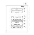
制御部13は記憶部を含むコンピュータで構成され、図8に制御部13の機能ブロック図の一例を示す。図8では全ての実施の形態に係る構成がまとめて示されている。制御部13はタイマ131、記憶手段132、第一の駆動停止手段133、第二の駆動停止手段134、切換手段135、駆動停止手段136、発電トルク制御手段137を含む。
The
続いて、図2を参照しながら、制御部13の制御による電力変換装置10の動作を説明する。図2は、制御部13の制御による駆動モードを終了する際の電力変換装置の動作を示すフローチャートである。まず、ステップS1において、次の動作モード指令が発電モードまたは制動モードかを判定する。次のモード指令が発電モードまたは制動モードの時、ステップS2へ進む。そうでない場合、すなわち次のモード指令が発電モードおよび制動モード以外の例えば停止モード等のその他のモードの場合、ステップS3へ進む。
Next, the operation of the
ステップS2では、電機子(22)側の駆動動作を停止させ、駆動動作を終了し、発電モードまたは制動モードへ遷移する。すなわち、次の動作モード指令が発電モードの場合、界磁電力変換部11による界磁電流の低減処理を行わず、界磁電力変換部11、電機子電力変換部12を制御して、ただちに駆動モードを終了し、発電モードへ遷移する。同様に、動作モード指令が制動モードの場合、界磁電力変換部11による界磁電流の低減処理を行わず、界磁電力変換部11、電機子電力変換部12を制御して、ただちに駆動モードを終了し、制動モードへ遷移する。
In step S2, the driving operation on the armature (22) side is stopped, the driving operation is terminated, and the mode is changed to the power generation mode or the braking mode. That is, when the next operation mode command is the power generation mode, the field
一方、ステップS3では、電機子電力変換部12を制御して電機子の通電を継続したままま、界磁電力変換部11の制御を止めて界磁巻線21への通電を停止させることで、界磁電流を低減させる(低減動作)。その後、ステップS4において、低減動作完了判定用の界磁電流レベルを演算する。この界磁電流レベルについては、例えば上述の特許文献1の発明のように、発電電動機1の回転速度と、B端子電圧(図1の符号Bの入出力端子電圧)またはバッテリ電圧(規格のバッテリ電圧:12V,24V,36V等)とを用いて、誘起電圧がB端子電圧またはバッテリ電圧を下回るような範囲の値を求める。このための制御部13はB端子電圧を得るために入出力端子Bにも接続されている。また制御部13の記憶手段132に使用バッテリの規格電圧が格納されている。後述するように、発電電動機1の回転速度、B端子電圧またはバッテリ電圧毎の上記界磁電流レベルをテーブルや数式等にして低減動作完了判定用(界磁電流レベル)情報として予め記憶手段132に格納しておいてもよい。
On the other hand, in step S3, by controlling the armature
ここで制御部13は、発電電動機1の回転速度は回転電機20の回転位置を検出する位置センサ23からの位置の時間的変化から求め、界磁電流は電流センサ14から得る。そして、回転電機20の誘起電圧、回転速度、界磁電流はおおよそ以下の関係にある。
(誘起電圧)=(係数)×(回転速度)×(界磁電流)
(界磁電流)=(誘起電圧)/{(係数)×(回転速度)}Here, the
(Induced voltage) = (coefficient) x (rotational speed) x (field current)
(Field current) = (Induced voltage) / {(Coefficient) × (Rotational speed)}
低減動作完了判定用の界磁電流レベルを求めた後、ステップS5において、界磁電流の値がこの低減動作完了判定用の界磁電流レベル(所定の閾値)以下か否かを判定する。界磁電流の値がこの低減動作完了判定用の界磁電流レベル以下であれば、この段階で電機子電力変換部12の制御を止めて電機子側への通電を停止しても、誘起電圧で意図しない発電を行うことは無いため、ステップS2へ進み、電機子側の駆動動作を停止させ、駆動動作を終了する。
After obtaining the field current level for determining the reduction operation completion, in step S5, it is determined whether or not the value of the field current is equal to or less than the field current level for determining the reduction operation completion (predetermined threshold). If the value of the field current is equal to or lower than the field current level for determining the completion of the reduction operation, the induced voltage can be induced even if the control of the armature
一方、ステップS5において、界磁電流の値がこの低減動作完了判定用の界磁電流レベルを上回っている場合、ステップS6へ進む。この時点で電機子側の駆動動作を停止させると、発電の指令をしていないのに発電を行ってしまうため、ステップS6では駆動モードの電機子通電制御を継続する。その後、ステップS1へ進み、この一連のフロー(ステップS5→S6→S1→S3→S4→S5)を繰り返すことで、界磁電流が低減動作判定完了用の界磁レベル以下まで低下するのを待ってから、駆動を停止する。 On the other hand, when the field current value exceeds the field current level for determining the completion of the reduction operation in step S5, the process proceeds to step S6. If the driving operation on the armature side is stopped at this time, the power generation is performed even though the power generation command is not issued. Therefore, in step S6, the armature energization control in the drive mode is continued. Thereafter, the process proceeds to step S1, and this series of flows (steps S5 → S6 → S1 → S3 → S4 → S5) is repeated to wait for the field current to fall below the field level for completion of the reduction operation determination. Then stop driving.
なお、ステップS1が切換手段135、ステップS2が第一の駆動停止手段133、ステップS1〜S6が第二の駆動停止手段134を構成する。
Step S1 constitutes the switching means 135, step S2 constitutes the first drive stopping means 133, and steps S1 to S6 constitute the second
この実施の形態では、駆動モードから発電モードへの遷移、または駆動モードから制動モードへの遷移の場合のみ、界磁の立下りを待たずに、すぐに駆動を停止し、発電または制動へ遷移させる。それ以外の動作モードの場合は、界磁電流が一定値以下になってから駆動を停止し、次の動作モードへ遷移させる。駆動モードは必須であるが、発電モード、制動モードはどちらか1つがあればよく、特に制動モードは無くてもよい。 In this embodiment, only in the transition from the drive mode to the power generation mode or from the drive mode to the braking mode, the driving is stopped immediately without waiting for the field to fall, and the transition is made to power generation or braking. Let In other operation modes, the drive is stopped after the field current becomes a certain value or less, and the operation mode is changed to the next operation mode. The drive mode is indispensable, but it is only necessary to have one of the power generation mode and the braking mode, and there is no particular need for the braking mode.
以上のように、この実施の形態においては、駆動を終了する際に、次のモード指令が発電モードまたは制動モードの場合には、界磁電流の低減を待つことなくただちに発電モードまたは制動モードへ遷移し、そうでない場合には残留界磁電流によって意図しない発電を行わないよう、低減処理を行ってから駆動を終了する。そのため、次の動作モード指令が発電モードまたは制動モードの場合には速やかに発電動作または制動動作を行うことができ、それ以外の停止モード等の場合には意図しない発電を防ぐことができる。 As described above, in this embodiment, when driving is ended, if the next mode command is the power generation mode or the braking mode, the mode is immediately switched to the power generation mode or the braking mode without waiting for the reduction of the field current. If not, the drive ends after performing a reduction process so that unintended power generation is not performed by the residual field current. Therefore, when the next operation mode command is the power generation mode or the braking mode, the power generation operation or the braking operation can be performed quickly, and when it is other than the stop mode, unintended power generation can be prevented.
なお、本実施の形態において次のモードが発電モードまたは制動モード以外の場合、駆動を停止するかどうかの判定に界磁電流レベル(閾値)を用いているが、これを界磁電流低減制御が開始してから(すなわち、次のモード指令を受信してから)の、界磁電流が上述の界磁電流レベルになるのに相当するそれぞれの所定の経過時間を用いて判定してもよい(所定時間経過後に駆動を停止)。この場合、時間経過は例えばタイマ131でカウントする。このような場合も、例えば、遷移する各動作モード、発電電動機1の回転速度、B端子電圧またはバッテリ電圧毎の経過時間を低減動作完了判定用(経過時間)情報として数式またはテーブルとして記憶手段132に予め記憶しておき、これを使用するようにしてもよい。
In the present embodiment, when the next mode is other than the power generation mode or the braking mode, the field current level (threshold) is used to determine whether to stop driving. The determination may be made using each predetermined elapsed time corresponding to the field current reaching the above-described field current level after starting (that is, after receiving the next mode command) ( The drive is stopped after a predetermined time). In this case, the elapsed time is counted by the
実施の形態2.
次に、この発明の実施の形態2による車両用発電電動機の電力変換装置ついて説明する。図3はこの発明の実施の形態2による、制御部13の制御による駆動モードを終了する際の電力変換装置の動作を示すフローチャートである。駆動モードを終了する際の電力変換装置の動作以外は、実施の形態1と同様であるため、説明を省略する。
Next, a power conversion device for a vehicular generator-motor according to
まず、ステップS11において、界磁電流の低減処理(低減動作)を開始する。この低減処理は、実施の形態1と同様である。 First, in step S11, field current reduction processing (reduction operation) is started. This reduction process is the same as in the first embodiment.
次に、ステップS12では、低減動作完了判定用の界磁電流レベルIfthを演算する。この界磁電流レベルIfthは、図4に示すように、次の動作モード指令、B端子電圧またはバッテリ電圧、回転速度から定まる値を用いる。 Next, in step S12, a field current level Ifth for determining the reduction operation completion is calculated. As the field current level Ifth, as shown in FIG. 4, a value determined from the next operation mode command, the B terminal voltage or the battery voltage, and the rotation speed is used.
例えば図4では、発電電動機の回転速度Nmgと遷移する動作モードに対する界磁電流レベルIfth(閾値)が示されている。Aは次の動作モードが発電モードの時のIfth、Bは次の動作モードが発電モード以外の時のIfthを示す。発電モードの界磁電流レベルIfthは発電モード以外の停止モード等の界磁電流レベルIfthより高く設定されている。このような関係がバッテリ電圧毎(VB=12V,24V,36V)に設定されている。同様にして検出したB端子電圧ごとに設定しておくことも可能であり、また数式として規定しておくことも可能である。このような情報(低減動作完了判定用情報)は例えば記憶手段132に予め格納しておき、使用することが可能である。
特に界磁電流レベルIfth(閾値)は、回転電機が次に遷移する動作モードが発電モードの場合、モード遷移直後の発電電流が所定値以下になるように設定される。For example, FIG. 4 shows the field current level Ifth (threshold) with respect to the operation mode in which the rotational speed Nmg of the generator motor transitions. A indicates Ifth when the next operation mode is the power generation mode, and B indicates Ifth when the next operation mode is other than the power generation mode. The field current level Ifth in the power generation mode is set higher than the field current level Ifth in the stop mode other than the power generation mode. Such a relationship is set for each battery voltage (VB = 12V, 24V, 36V). Similarly, it can be set for each detected B terminal voltage, or can be defined as an equation. Such information (reduction operation completion determination information) can be stored in advance in the
In particular, the field current level Ifth (threshold) is set so that the generated current immediately after the mode transition is equal to or less than a predetermined value when the operation mode in which the rotating electrical machine transitions next is the power generation mode.
次の動作モード指令(遷移先モード)が発電モードの時には、低減動作完了判定用の界磁電流レベルIfth(閾値)を発電時の最大界磁電流IfMAX付近に設定し、なるべく早い段階で駆動モードから発電モードへ遷移できるようにする。
ただし、高回転かつ大きな界磁電流が流れている状態で駆動モードから発電モードに遷移した場合、遷移直後に過大な発電電流が生じ、場合によっては過電圧を引き起こすことがある。そのような場合は、図4の破線で示すように、界磁電流レベルIfthの値を発電電流がある一定の値を超えないような範囲で定める。When the next operation mode command (transition destination mode) is the power generation mode, the field current level Ifth (threshold) for determining the reduction operation completion is set near the maximum field current IfMAX during power generation, and the drive mode is set as early as possible. It is possible to transition from power generation mode to power generation mode.
However, when a transition is made from the drive mode to the power generation mode in a state where high rotation and a large field current are flowing, an excessive power generation current is generated immediately after the transition, and an overvoltage may be caused in some cases. In such a case, as indicated by a broken line in FIG. 4, the value of the field current level Ifth is determined in a range in which the generated current does not exceed a certain value.
一方、次の動作モード指令が停止モードの時には、特許文献1の発明のように、発電電動機の回転速度とB端子電圧またはバッテリ電圧を用いて、誘起電圧がB端子電圧またはバッテリ電圧を下回るような範囲の界磁電流レベルIfth(閾値)を設定し、意図しない発電を防止する。
なお、一般的な12V鉛バッテリを使用する場合、B端子電圧の変動幅は少なく、界磁電流レベルIfthに与える影響は小さいため、これを一定として扱ってもよい。すなわち、入出力端子から検出せずに、記憶手段132等に予め格納された規格のバッテリ電圧または規格のバッテリ電圧ごとの情報(図4参照)を使用する。On the other hand, when the next operation mode command is the stop mode, as in the invention of
When a general 12V lead battery is used, the fluctuation range of the B terminal voltage is small and the influence on the field current level Ifth is small. That is, the standard battery voltage stored in advance in the storage means 132 or the like or information for each standard battery voltage (see FIG. 4) is used without detection from the input / output terminals.
低減動作完了判定用の界磁電流レベルを求めた後、ステップS13において、界磁電流の値がこの低減動作完了判定用の界磁電流レベルIfth(閾値)以下か否かを判定する。界磁電流の値がこの低減動作完了判定用の界磁電流レベル以下であれば、この段階で電機子側への通電を停止しても、意図しない発電を行うことは無いため、ステップS14へ進み、電機子側の駆動動作を停止させ、駆動動作を終了する。 After obtaining the field current level for determining the reduction operation completion, in step S13, it is determined whether or not the value of the field current is equal to or less than the field current level Ifth (threshold value) for determining the reduction operation completion. If the value of the field current is equal to or less than the field current level for determining the completion of the reduction operation, unintentional power generation is not performed even if the energization to the armature side is stopped at this stage, so go to Step S14. The driving operation on the armature side is stopped and the driving operation is terminated.
一方、界磁電流の値がこの低減動作完了判定用の界磁電流レベルを上回っている場合、ステップS15へ進む。この時点で電機子側の駆動動作を停止させると、発電の指令をしていないのに発電を行ってしまうため、ステップS15では駆動モードの電機子通電制御を継続する。その後、ステップS11へ進み、この一連のフロー(ステップS13→S15→S11→S12→S13)を繰り返すことで、界磁電流が低減動作判定完了用の界磁レベル以下まで低下するのを待ってから、駆動を停止する。 On the other hand, when the value of the field current exceeds the field current level for determining the completion of the reduction operation, the process proceeds to step S15. If the driving operation on the armature side is stopped at this time, the power generation is performed even though the power generation command is not issued. Therefore, in step S15, the armature energization control in the drive mode is continued. Thereafter, the process proceeds to step S11, and after repeating this series of steps (steps S13, S15, S11, S12, and S13), the field current waits for the field level to decrease to a field level for completion of the reduction operation determination. Stop driving.
なお、ステップS11〜S15が駆動停止手段136を構成する。また、低減動作完了判定用の界磁電流レベルIfth(閾値)は上述のように計算で求めてもよいし、また図4に示すような低減動作完了判定用(界磁電流レベル)情報を数式またはテーブルとして記憶手段132に予め格納しておき、これを使用するようにしてもよい。 Steps S11 to S15 constitute the drive stopping means 136. Further, the field current level Ifth (threshold) for determining the reduction operation completion may be obtained by calculation as described above, or the information for determining the reduction operation completion (field current level) as shown in FIG. Alternatively, it may be stored in advance in the storage means 132 as a table and used.
この実施の形態では、駆動モードから駆動モード以外の他の動作モード(次モード)に遷移する際の電機子側の通電を停止する界磁電流の閾値を、次動作モードに従って変化させる。例えば、駆動モードから発電モードへの遷移の場合、10Aまで界磁電流が低下したら電機子側の通電を停止させ、駆動モードから停止モードへの遷移の場合、0.5Aまで低下したら電機子側の通電を停止させる。 In this embodiment, the field current threshold for stopping energization on the armature side at the time of transition from the drive mode to another operation mode (next mode) other than the drive mode is changed according to the next operation mode. For example, in the case of a transition from the drive mode to the power generation mode, the energization on the armature side is stopped when the field current decreases to 10 A, and in the case of the transition from the drive mode to the stop mode, the armature side Stop energizing.
さらに、次モード情報と、回転速度、B端子電圧またはバッテリ電圧によって変化させる。例えば、駆動モードから発電モードへの遷移の場合、1000r/min、VB=12Vなら10Aまで界磁電流が低下したら電機子側の通電を停止させ、2000r/min、VB=18Vなら6Aまで界磁電流が低下したら電機子側の通電を停止させる。 Further, it is changed by the next mode information, the rotation speed, the B terminal voltage or the battery voltage. For example, in the case of transition from the drive mode to the power generation mode, if the field current decreases to 10 A if 1000 r / min and VB = 12 V, the armature side energization is stopped, and if 2000 r / min and VB = 18 V, the field is increased to 6 A. When the current decreases, the energization on the armature side is stopped.
以上のように、この実施の形態においては、駆動を終了する際に、界磁電流の低減動作を行い、その低減動作の完了判定用界磁電流レベルを次の動作モード指令、B端子電圧、回転速度によって演算または記憶手段で検索する。そのため、次の動作モード指令が発電の場合には速やかに発電動作を行うことができるうえ、それ以外の動作モードの場合には意図しない発電を防ぐことができる。 As described above, in this embodiment, when the driving is finished, the field current is reduced, and the reduction operation completion determination field current level is set to the next operation mode command, B terminal voltage, Search by calculation or storage means according to the rotation speed. Therefore, when the next operation mode command is power generation, power generation operation can be performed promptly, and unintended power generation can be prevented in other operation modes.
なお、本実施の形態においても、駆動を停止するかどうかの判定に界磁電流レベル(閾値)を用いているが、これを界磁電流低減制御が開始してから(すなわち、次のモード指令を受信してから)の、界磁電流が上述の界磁電流レベルになるのに相当するそれぞれの所定の経過時間を用いて判定してもよい。このような場合も、例えば、遷移する各動作モード、発電電動機1の回転速度、B端子電圧またはバッテリ電圧毎の経過時間を低減動作完了判定用(経過時間)情報として数式またはテーブルとして記憶手段132に予め記憶しておき、これを使用するようにしてもよい。
そして界磁電流レベルIfth(閾値)は、次に遷移する動作モードと発電電動機の回転速度に基づいて設定されてもよいし、B端子電圧またはバッテリ電圧をさらに加えたものに基づいて設定されてもよい。Even in the present embodiment, the field current level (threshold) is used to determine whether or not to stop the drive, but this is determined after the field current reduction control is started (that is, the next mode command It may be determined using each predetermined elapsed time corresponding to the field current reaching the above-described field current level. Also in such a case, for example, each operation mode to be transitioned, the rotation speed of the
The field current level Ifth (threshold value) may be set based on the next transition operation mode and the rotational speed of the generator motor, or may be set based on the addition of the B terminal voltage or the battery voltage. Also good.
実施の形態3.
実施の形態3は、実施の形態2に対して、低減動作完了判定用の界磁電流レベルの演算方法を変更したものである。その他の部分は実施の形態2と同様のため、以下には実施の形態3に特有の部分のみについて説明する。Embodiment 3 FIG.
The third embodiment is different from the second embodiment in the field current level calculation method for determining the reduction operation completion. Since other parts are the same as those in the second embodiment, only the parts peculiar to the third embodiment will be described below.
従来より、上位のコントローラから指令される発電トルクの指令値と、回転速度などから、対応する界磁電流指令を求め、その界磁電流の指令値に従って界磁電流制御を行うことで、所望のトルクを発生させる、発電トルク制御が提案されている(例えば、上記特許文献3) Conventionally, a desired field current command is obtained from the command value of the power generation torque commanded from the host controller and the rotation speed, and the field current control is performed according to the command value of the field current. A power generation torque control that generates torque has been proposed (for example, Patent Document 3).
このような発電トルク制御機能を持つ発電電動機で実施の形態2のような制御を行う場合のトルクと界磁電流の関係の一例を図5に示す。図5の(a)はトルク、(b)は界磁電流のそれぞれ経時変化を示す。例えば図5に示すように、発電トルク指令Tgが微小で、かつ駆動時の界磁電流が大きい場合、界磁電流が大きいまますぐに駆動モードから発電モードへ遷移するため、発電時の最大界磁電流に近い状態での発電を行うことになり、必要以上の発電トルクが発生する。 FIG. 5 shows an example of the relationship between torque and field current when such a generator motor having a power generation torque control function performs control as in the second embodiment. In FIG. 5, (a) shows the change over time, and (b) shows the change over time in the field current. For example, as shown in FIG. 5, when the power generation torque command Tg is small and the field current at the time of driving is large, the field current remains large, and the mode immediately shifts from the driving mode to the power generation mode. Power generation is performed in a state close to the magnetic current, and more power generation torque than necessary is generated.
そのため、この実施の形態においては、前述したような必要以上のトルク発生を防ぐため、図6に示すように発電トルク指令、回転速度、B端子電圧またはバッテリ電圧をもとに演算された、発電トルク制御時の界磁電流指令Ifgを、低減動作完了判定用の界磁電流レベルIfthとして用いる。発電トルク指令は動作指令OCに含まれる。
この実施の形態では、駆動モードから発電モードへ遷移する場合、発生するトルクが発電モードのトルク指令まで下がってから、発電モードへ切換える。Therefore, in this embodiment, in order to prevent generation of excessive torque as described above, the power generation calculated based on the power generation torque command, the rotation speed, the B terminal voltage, or the battery voltage as shown in FIG. The field current command Ifg at the time of torque control is used as the field current level Ifth for determining the reduction operation completion. The power generation torque command is included in the operation command OC.
In this embodiment, when transitioning from the drive mode to the power generation mode, the generated torque decreases to the torque command in the power generation mode, and then the mode is switched to the power generation mode.
例えば図6では、発電電動機の回転速度Nmgと発電時のトルク指令Tg=T1,T2、T3(T1>T2>T3)に対する発電時開示電流指令Ifgが示されている。そしてこのような関係が各B端子電圧またはバッテリ電圧毎(VB=12V,24V,36V)に設定されている。そしてこのような低減動作完了判定用(界磁電流レベル)情報は数式またはテーブルとして例えば記憶手段132に予め格納しておき、使用するようにしてもよい。
For example, FIG. 6 shows a power generation disclosure current command Ifg with respect to the rotational speed Nmg of the generator motor and the torque commands Tg = T1, T2, and T3 (T1> T2> T3) during power generation. Such a relationship is set for each B terminal voltage or each battery voltage (VB = 12V, 24V, 36V). Such reduction operation completion determination (field current level) information may be stored in advance in, for example, the
これによって、図7に示したように、駆動モードから発電モードへ遷移する際の必要以上の発電トルクの発生を防止することができる。図7の(a)(b)は図5の(a)(b)に対応するそれぞれトルク、界磁電流のそれぞれ経時変化を示す。 As a result, as shown in FIG. 7, it is possible to prevent generation of excessive power generation torque at the time of transition from the drive mode to the power generation mode. (A) and (b) of FIG. 7 show changes with time of torque and field current corresponding to (a) and (b) of FIG. 5, respectively.
なお、上記処理は図8の発電トルク制御手段137で行われる。外部からの動作指令に発電トルク指令が含まれており、発電トルク制御手段137は、発電時に回転電機20が発生するトルクが外部から与えられる発電トルク指令と一致するように発電電力を制御する。そして回転電機20が次に遷移する動作モードが発電モードの場合、界磁電流の閾値が、発電トルク指令値に従って設定される。
The above processing is performed by the power generation torque control means 137 in FIG. A power generation torque command is included in the operation command from the outside, and the power generation torque control means 137 controls the generated power so that the torque generated by the rotating
以上のように、この実施の形態においては、駆動モードを終了し発電モードへ遷移する際に、低減動作を行い、その低減動作の完了判定用界磁電流レベルをB端子電圧、回転速度、発電時のトルク指令によって演算する。そのため、次の動作モード指令が発電の場合には速やかに発電動作を行うことができるうえ、必要以上の発電トルクの発生を防ぐことができる。 As described above, in this embodiment, when the drive mode is ended and the mode is changed to the power generation mode, the reduction operation is performed, and the field current level for determining the completion of the reduction operation is set to the B terminal voltage, the rotation speed, and the power generation. Calculated according to the torque command at the time. Therefore, when the next operation mode command is power generation, power generation operation can be performed promptly, and generation of excessive power generation torque can be prevented.
なお、本実施の形態中では、外部からトルク指令を受け、発電トルク制御を行う場合における、必要以上の発電トルクが発生することを防止する方法について述べたが、発電電圧制御などの場合でも、トルクの急変を防ぐために、制御部13の記憶手段132に予め格納したトルク制限値をもとに、上記の動作を行ってもよい。その場合、本実施の形態中の「発電トルク指令」はそのまま「発電トルク制限値」と置き換えて考えることができる。
In the present embodiment, a method for preventing generation of excessive power generation torque in the case of performing power generation torque control by receiving a torque command from the outside has been described, but even in the case of power generation voltage control or the like, In order to prevent a sudden change in torque, the above operation may be performed based on a torque limit value stored in advance in the
すなわち、この場合、外部からの動作指令に発電トルク指令の代わりに発電トルク制限値が含まれており、発電トルク制御手段137は、発電時に回転電機20が発生するトルクが該発電トルク制限値以下となるように発電電力を制御し、回転電機20が次に遷移する動作モードが発電モードの場合、界磁電流の閾値を、前記発電トルク制限値に従って設定する。
That is, in this case, the operation command from the outside includes a power generation torque limit value instead of the power generation torque command, and the power generation torque control means 137 has the torque generated by the rotating
発電トルク指令を使用する場合、定められたトルクとなるよう運転することを想定しているが、発電トルク制限値を使用する場合、基本的には電圧制御をしつつ、最大トルクは制限する運転制御となる。 When using the power generation torque command, it is assumed that the motor will be operated to the specified torque, but when using the power generation torque limit value, basically the voltage control is performed and the maximum torque is limited. It becomes control.
また、この発明は上記各実施の形態に限定されるものではなく、これら実施の形態の可能な組み合わせを全て含むことは云うまでもない。 Further, the present invention is not limited to the above embodiments, and it is needless to say that all possible combinations of these embodiments are included.
この発明による車両用発電電動機の電力変換装置および車両用発電電動機の制御方法は多くの分野の車両用発電電動機に適用可能であり、同様な効果を奏する。 The power converter for a vehicular generator / motor and the control method for the vehicular generator / motor according to the present invention are applicable to vehicular generator / motors in many fields, and have the same effects.
1 発電電動機、2 バッテリ(キャパシタ)、3 エンジン、4 動力伝達部、10 電力変換装置、11 界磁電力変換部、12 電機子電力変換部、13 制御部、14 電流センサ、20 回転電機、21 界磁巻線、22 電機子巻線、23 位置センサ、131 タイマ、132 記憶手段、133 第一の駆動停止手段、134 第二の駆動停止手段、135 切換手段、136 駆動停止手段、137 発電トルク制御手段、B,E 入出力端子。
DESCRIPTION OF
Claims (11)
前記界磁巻線と電力の入出力端子間に接続され、界磁巻線に流れる界磁電流を制御する界磁電力変換部と、
前記電機子巻線と前記入出力端子間に接続され、交直相互変換を行う電機子電力変換部と、
前記動作指令に基づく前記回転電機の動作モードに応じて前記界磁電力変換部と前記電機子電力変換部を制御する制御部を備え、
前記制御部は、
前記入出力端子から供給される直流電力を交流電力に変換し前記回転電機に駆動トルクを発生させる駆動モード、
前記回転電機で発電された交流電力を直流電力に変換し前記入出力端子に接続された外部の負荷へ供給する発電モード、および
前記回転電機で発電された交流電力を前記回転電機内部および前記電力変換装置内部で消費し、制動トルクを発生させる制動モード、
のうち、前記駆動モードと少なくとも前記発電モードまたは制動モードを含む複数の動作モード間で動作モードを切換え、
前記駆動モードから他のモードへ遷移する際に、次に遷移するモードの種類に従って前記電機子巻線の電機子電流の通電を停止するタイミングを変え、
前記制御部は、前記回転電機の動作を駆動モードから他の動作モードに遷移させる際に、ただちに前記電機子電力変換部に電機子電流の通電を停止させる第一の駆動停止手段と、
前記界磁電力制御部に界磁電流の低減処理を開始させ、その後、界磁電流が所定の閾値以下になった場合に、前記電機子電力変換部に電機子電流の通電を停止させる第二の駆動停止手段と、
駆動モードから発電モードまたは制動モードに遷移させる際には前記第一の駆動停止手段を使用し、駆動モードから発電モードまたは制動モード以外に遷移させる際には前記第二の駆動停止手段を使用するように切り換える切換手段と、
含む、
ことを特徴とする車両用発電電動機の電力変換装置。 A power converter for a vehicular generator motor that is connected to a rotating electrical machine having a field winding and an armature winding and performs control according to an operation command from the outside,
A field power converter connected between the field winding and the power input / output terminal and controlling a field current flowing in the field winding;
An armature power converter connected between the armature winding and the input / output terminal and performing AC / DC mutual conversion;
A control unit that controls the field power conversion unit and the armature power conversion unit according to an operation mode of the rotating electrical machine based on the operation command;
The controller is
A driving mode for converting the DC power supplied from the input / output terminal into AC power and generating a driving torque in the rotating electrical machine;
A power generation mode for converting AC power generated by the rotating electrical machine into DC power and supplying it to an external load connected to the input / output terminal; and AC power generated by the rotating electrical machine inside the rotating electrical machine and the power A braking mode that consumes inside the converter and generates braking torque,
Among them, the operation mode is switched between a plurality of operation modes including the drive mode and at least the power generation mode or the braking mode,
When switching from the drive mode to another, then ging the timing of stopping the energization of the armature current of the armature windings according to the type of mode transition,
The control unit, when transitioning the operation of the rotating electrical machine from the drive mode to another operation mode, a first drive stop unit that immediately stops energization of the armature current to the armature power conversion unit;
The field power control unit starts field current reduction processing, and then, when the field current falls below a predetermined threshold, the armature power conversion unit stops energization of the armature current. Driving stop means,
The first drive stop means is used when changing from the drive mode to the power generation mode or the braking mode, and the second drive stop means is used when changing from the drive mode to a mode other than the power generation mode or the brake mode. Switching means for switching
Including,
A power conversion device for a vehicular generator motor.
前記界磁巻線と電力の入出力端子間に接続され、界磁巻線に流れる界磁電流を制御する界磁電力変換部と、
前記電機子巻線と前記入出力端子間に接続され、交直相互変換を行う電機子電力変換部と、
前記動作指令に基づく前記回転電機の動作モードに応じて前記界磁電力変換部と前記電機子電力変換部を制御する制御部を備え、
前記制御部は、
前記入出力端子から供給される直流電力を交流電力に変換し前記回転電機に駆動トルクを発生させる駆動モード、
前記回転電機で発電された交流電力を直流電力に変換し前記入出力端子に接続された外部の負荷へ供給する発電モード、および
前記回転電機で発電された交流電力を前記回転電機内部および前記電力変換装置内部で消費し、制動トルクを発生させる制動モード、
のうち、前記駆動モードと少なくとも前記発電モードまたは制動モードを含む複数の動作モード間で動作モードを切換え、
前記駆動モードから他のモードへ遷移する際に、次に遷移するモードの種類に従って前記電機子巻線の電機子電流の通電を停止するタイミングを変え、
前記制御部は、前記回転電機の動作を駆動モードから他の動作モードに遷移させる際に、前記界磁電力変換部に界磁電流の低減処理を開始させ、その後、界磁電流が、遷移する動作モードによって設定されたそれぞれの所定の閾値以下になった場合に、前記電機子電力変換部に電機子電流の通電を停止させる駆動停止手段を含む、
ことを特徴とする車両用発電電動機の電力変換装置。 A power converter for a vehicular generator motor that is connected to a rotating electrical machine having a field winding and an armature winding and performs control according to an operation command from the outside,
A field power converter connected between the field winding and the power input / output terminal and controlling a field current flowing in the field winding;
An armature power converter connected between the armature winding and the input / output terminal and performing AC / DC mutual conversion;
A control unit that controls the field power conversion unit and the armature power conversion unit according to an operation mode of the rotating electrical machine based on the operation command;
The controller is
A driving mode for converting the DC power supplied from the input / output terminal into AC power and generating a driving torque in the rotating electrical machine;
A power generation mode for converting AC power generated by the rotating electrical machine into DC power and supplying it to an external load connected to the input / output terminal; and AC power generated by the rotating electrical machine inside the rotating electrical machine and the power A braking mode that consumes inside the converter and generates braking torque,
Among them, the operation mode is switched between a plurality of operation modes including the drive mode and at least the power generation mode or the braking mode,
When transitioning from the drive mode to another mode, change the timing to stop energization of the armature current of the armature winding according to the type of mode to transition next ,
The control unit causes the field power conversion unit to start a field current reduction process when the operation of the rotating electrical machine is changed from the drive mode to another operation mode, and then the field current changes. Including drive stop means for stopping energization of the armature current in the armature power conversion section when each of the armature power conversion units is equal to or less than a predetermined threshold set by the operation mode.
A power conversion device for a vehicular generator motor.
前記界磁巻線と電力の入出力端子間に接続された界磁電力変換部により界磁巻線に流れる界磁電流を制御し、
前記電機子巻線と前記入出力端子間に接続された電機子電力変換部により交直相互変換を行い、
制御部により前記動作指令に従った前記回転電機の動作モードに応じて前記界磁電力変換部と前記電機子電力変換部を制御し、
前記入出力端子から供給される直流電力を交流電力に変換し前記回転電機に駆動トルクを発生させる駆動モード、
前記回転電機で発電された交流電力を直流電力に変換し前記入出力端子に接続された外部の負荷へ供給する発電モード、および
前記回転電機で発電された交流電力を前記回転電機内部および前記電力変換装置内部で消費し、制動トルクを発生させる制動モードのうち、
前記駆動モードと少なくとも前記発電モードまたは制動モードを含む動作モード間で動作モードを切換え、前記駆動モードから他のモードへ遷移する際に、次に遷移するモードの種類に従って前記電機子巻線の電機子電流の通電を停止するタイミングを変え、
前記回転電機の動作を駆動モードから他の動作モードに遷移させる際に、ただちに前記電機子電力変換部に電機子電流の通電を停止させる第一の駆動停止と、
前記界磁電力制御部に界磁電流の低減処理を開始させ、その後、界磁電流が所定の閾値以下になった場合に、前記電機子電力変換部に電機子電流の通電を停止させる第二の駆動停止と、を行い、
駆動モードから発電モードまたは制動モードに遷移させる際には前記第一の駆動停止を行い、駆動モードから発電モードまたは制動モード以外に遷移させる際には前記第二の駆動停止を行うように切り換える、
ことを特徴とする車両用発電電動機の制御方法。 A control method for a vehicular generator motor in which a power converter is connected to a rotating electrical machine having a field winding and an armature winding and performs control according to an operation command from the outside,
Control the field current flowing in the field winding by the field power converter connected between the field winding and the power input / output terminal,
AC / DC mutual conversion is performed by an armature power conversion unit connected between the armature winding and the input / output terminal,
Control the field power conversion unit and the armature power conversion unit according to the operation mode of the rotating electrical machine according to the operation command by the control unit,
A driving mode for converting the DC power supplied from the input / output terminal into AC power and generating a driving torque in the rotating electrical machine;
A power generation mode for converting AC power generated by the rotating electrical machine into DC power and supplying it to an external load connected to the input / output terminal; and AC power generated by the rotating electrical machine inside the rotating electrical machine and the power Of the braking modes that are consumed inside the converter and generate braking torque,
When the operation mode is switched between the drive mode and an operation mode including at least the power generation mode or the braking mode, and the mode is changed from the drive mode to another mode, the armature winding is operated according to the type of the mode to be changed next. Change the timing to stop energizing the child current ,
When the operation of the rotating electrical machine is shifted from the drive mode to another operation mode, a first drive stop that immediately stops energization of the armature current to the armature power conversion unit;
The field power control unit starts field current reduction processing, and then, when the field current falls below a predetermined threshold, the armature power conversion unit stops energization of the armature current. And stop driving,
When changing from the drive mode to the power generation mode or the braking mode, the first drive stop is performed, and when changing from the drive mode to the power generation mode or the braking mode, the second drive stop is performed.
A control method for a vehicular generator motor.
前記界磁巻線と電力の入出力端子間に接続された界磁電力変換部により界磁巻線に流れる界磁電流を制御し、
前記電機子巻線と前記入出力端子間に接続された電機子電力変換部により交直相互変換を行い、
制御部により前記動作指令に従った前記回転電機の動作モードに応じて前記界磁電力変換部と前記電機子電力変換部を制御し、
前記入出力端子から供給される直流電力を交流電力に変換し前記回転電機に駆動トルクを発生させる駆動モード、
前記回転電機で発電された交流電力を直流電力に変換し前記入出力端子に接続された外部の負荷へ供給する発電モード、および
前記回転電機で発電された交流電力を前記回転電機内部および前記電力変換装置内部で消費し、制動トルクを発生させる制動モードのうち、
前記駆動モードと少なくとも前記発電モードまたは制動モードを含む動作モード間で動作モードを切換え、前記駆動モードから他のモードへ遷移する際に、次に遷移するモードの種類に従って前記電機子巻線の電機子電流の通電を停止するタイミングを変え、
前記回転電機の動作を駆動モードから他の動作モードに遷移させる際に、前記界磁電力変換部に界磁電流の低減処理を開始させ、その後、界磁電流が、遷移する動作モードによって設定されたそれぞれの所定の閾値以下になった場合に、前記電機子電力変換部に電機子電流の通電を停止させる、
ことを特徴とする車両用発電電動機の制御方法。 A control method for a vehicular generator motor in which a power converter is connected to a rotating electrical machine having a field winding and an armature winding and performs control according to an operation command from the outside,
Control the field current flowing in the field winding by the field power converter connected between the field winding and the power input / output terminal,
AC / DC mutual conversion is performed by an armature power conversion unit connected between the armature winding and the input / output terminal,
Control the field power conversion unit and the armature power conversion unit according to the operation mode of the rotating electrical machine according to the operation command by the control unit,
A driving mode for converting the DC power supplied from the input / output terminal into AC power and generating a driving torque in the rotating electrical machine;
A power generation mode for converting AC power generated by the rotating electrical machine into DC power and supplying it to an external load connected to the input / output terminal; and AC power generated by the rotating electrical machine inside the rotating electrical machine and the power Of the braking modes that are consumed inside the converter and generate braking torque,
When the operation mode is switched between the drive mode and an operation mode including at least the power generation mode or the braking mode, and the mode is changed from the drive mode to another mode, the armature winding is operated according to the type of the mode to be changed next. Change the timing to stop energizing the child current ,
When the operation of the rotating electrical machine is transitioned from the drive mode to another operation mode, the field power conversion unit is started to reduce the field current, and then the field current is set according to the transition operation mode. And when the armature power conversion unit stops energization of the armature current when each of the predetermined threshold values or less,
A control method for a vehicular generator motor.
Applications Claiming Priority (1)
| Application Number | Priority Date | Filing Date | Title |
|---|---|---|---|
| PCT/JP2012/055797 WO2013132606A1 (en) | 2012-03-07 | 2012-03-07 | Power converter for vehicle generator-motor and method for controlling vehicle generator-motor |
Publications (2)
| Publication Number | Publication Date |
|---|---|
| JP5726369B2 true JP5726369B2 (en) | 2015-05-27 |
| JPWO2013132606A1 JPWO2013132606A1 (en) | 2015-07-30 |
Family
ID=49116122
Family Applications (1)
| Application Number | Title | Priority Date | Filing Date |
|---|---|---|---|
| JP2014503355A Active JP5726369B2 (en) | 2012-03-07 | 2012-03-07 | VEHICLE GENERATOR MOTOR POWER CONVERTER AND VEHICLE GENERATOR MOTOR CONTROL METHOD |
Country Status (6)
| Country | Link |
|---|---|
| US (1) | US9533580B2 (en) |
| EP (1) | EP2824830B1 (en) |
| JP (1) | JP5726369B2 (en) |
| CN (1) | CN104160611B (en) |
| IN (1) | IN2014CN04924A (en) |
| WO (1) | WO2013132606A1 (en) |
Families Citing this family (5)
| Publication number | Priority date | Publication date | Assignee | Title |
|---|---|---|---|---|
| CN104104293B (en) * | 2014-07-16 | 2016-07-13 | 国家电网公司 | A kind of minimum exciting current method for limiting based on electromotor steady state stability limit |
| CN109152902B (en) * | 2016-05-09 | 2022-03-04 | Art医疗有限公司 | Intelligent ETT ventilation accessory and use method |
| US10804833B2 (en) * | 2016-11-02 | 2020-10-13 | Mitsubishi Electric Corporation | Control device for electric generator/motor and control method for electric generator/motor |
| JP6377190B2 (en) * | 2017-01-27 | 2018-08-22 | 三菱電機株式会社 | Control device and control method for rotating electrical machine |
| FR3077445B1 (en) * | 2018-01-30 | 2020-01-10 | Valeo Equipements Electriques Moteur | METHOD FOR OPTIMIZING THE TRANSFER FROM ONE OPERATING MODE TO ANOTHER FOR A ROTATING ELECTRIC MACHINE |
Citations (4)
| Publication number | Priority date | Publication date | Assignee | Title |
|---|---|---|---|---|
| JP2003061398A (en) * | 2001-08-20 | 2003-02-28 | Denso Corp | Generator-motor equipment for vehicle |
| JP4185094B2 (en) * | 2005-12-20 | 2008-11-19 | 三菱電機株式会社 | Rotating electrical machine equipment |
| JP2010081709A (en) * | 2008-09-25 | 2010-04-08 | Mitsubishi Electric Corp | Field winding type synchronous power generator |
| JP2010081741A (en) * | 2008-09-26 | 2010-04-08 | Mitsubishi Electric Corp | Generator/motor controller and vehicle system equipped with the same |
Family Cites Families (13)
| Publication number | Priority date | Publication date | Assignee | Title |
|---|---|---|---|---|
| JP3517405B2 (en) | 2001-08-10 | 2004-04-12 | 三菱電機株式会社 | Control device and control method for rotating electric machine for vehicle |
| JP4376589B2 (en) * | 2003-10-29 | 2009-12-02 | 日産自動車株式会社 | Four-wheel drive vehicle |
| JP2006034027A (en) | 2004-07-20 | 2006-02-02 | Nissan Motor Co Ltd | Control unit of field winding electric motor |
| FR2881295B1 (en) * | 2005-01-26 | 2007-03-23 | Valeo Equip Electr Moteur | MANAGING THE OPERATION OF A MOTOR VEHICLE ALTERNATOR STARTER |
| JP4570982B2 (en) | 2005-02-25 | 2010-10-27 | 日立オートモティブシステムズ株式会社 | Power generation control device and power generation device |
| JP2007159353A (en) * | 2005-12-08 | 2007-06-21 | Mitsubishi Electric Corp | Field winding type synchronous generator motor |
| FR2918222B1 (en) * | 2007-06-27 | 2010-06-04 | Valeo Equip Electr Moteur | METHOD AND ELECTRIC BRAKE MACHINE OF A HEAT ENGINE AND VEHICLE DURING THE STOPPING PHASE THEREOF |
| JP4906825B2 (en) * | 2008-10-07 | 2012-03-28 | 三菱電機株式会社 | Vehicle behavior control device |
| JP5174617B2 (en) | 2008-10-30 | 2013-04-03 | 日立オートモティブシステムズ株式会社 | Rotating electrical machine device and control device thereof |
| JP2012228017A (en) * | 2011-04-18 | 2012-11-15 | Mitsubishi Electric Corp | Controller of generator-motor |
| JPWO2013171843A1 (en) * | 2012-05-15 | 2016-01-07 | 三菱電機株式会社 | Field winding type rotating electrical machine and field current control method for field winding type rotating electrical machine |
| JP5972385B2 (en) * | 2012-09-19 | 2016-08-17 | 三菱電機株式会社 | Field winding type rotating electrical machine |
| JP2014204451A (en) * | 2013-04-01 | 2014-10-27 | 三菱電機株式会社 | Controller of vehicular generator motor and method thereof |
-
2012
- 2012-03-07 EP EP12870716.3A patent/EP2824830B1/en active Active
- 2012-03-07 WO PCT/JP2012/055797 patent/WO2013132606A1/en active Application Filing
- 2012-03-07 IN IN4924CHN2014 patent/IN2014CN04924A/en unknown
- 2012-03-07 US US14/371,008 patent/US9533580B2/en active Active
- 2012-03-07 CN CN201280071234.4A patent/CN104160611B/en active Active
- 2012-03-07 JP JP2014503355A patent/JP5726369B2/en active Active
Patent Citations (4)
| Publication number | Priority date | Publication date | Assignee | Title |
|---|---|---|---|---|
| JP2003061398A (en) * | 2001-08-20 | 2003-02-28 | Denso Corp | Generator-motor equipment for vehicle |
| JP4185094B2 (en) * | 2005-12-20 | 2008-11-19 | 三菱電機株式会社 | Rotating electrical machine equipment |
| JP2010081709A (en) * | 2008-09-25 | 2010-04-08 | Mitsubishi Electric Corp | Field winding type synchronous power generator |
| JP2010081741A (en) * | 2008-09-26 | 2010-04-08 | Mitsubishi Electric Corp | Generator/motor controller and vehicle system equipped with the same |
Also Published As
| Publication number | Publication date |
|---|---|
| EP2824830A1 (en) | 2015-01-14 |
| US20150019059A1 (en) | 2015-01-15 |
| US9533580B2 (en) | 2017-01-03 |
| WO2013132606A1 (en) | 2013-09-12 |
| CN104160611A (en) | 2014-11-19 |
| EP2824830A4 (en) | 2016-08-03 |
| JPWO2013132606A1 (en) | 2015-07-30 |
| EP2824830B1 (en) | 2023-08-30 |
| CN104160611B (en) | 2016-09-28 |
| IN2014CN04924A (en) | 2015-09-18 |
Similar Documents
| Publication | Publication Date | Title |
|---|---|---|
| JP5955414B2 (en) | Motor control device | |
| WO2012164680A1 (en) | Vehicle and method of controlling vehicle | |
| JP2007074868A (en) | Voltage controller for vehicle | |
| JP5726369B2 (en) | VEHICLE GENERATOR MOTOR POWER CONVERTER AND VEHICLE GENERATOR MOTOR CONTROL METHOD | |
| JP6503636B2 (en) | Motor controller | |
| JP2006050695A (en) | Power generation control unit | |
| JP5079030B2 (en) | Control device for power converter | |
| JP5855128B2 (en) | Power converter and control method of power converter | |
| JP2005160247A (en) | Controller and control method of motor driven 4wd vehicle | |
| JP2006340599A (en) | Control unit of rotary electric machine for vehicles | |
| JP5644723B2 (en) | Power supply control device | |
| JP2007195352A (en) | Power supply unit for motor | |
| JP2005253213A (en) | Method and device for controlling multi-axis motor | |
| JP5214995B2 (en) | VEHICLE POWER CONVERSION DEVICE AND VEHICLE DRIVE CONTROL DEVICE | |
| JP4780171B2 (en) | Vehicle power generation control device | |
| JP2004320861A (en) | Controller for three-phase motor-generator for vehicle | |
| JP6656404B2 (en) | Generator motor control device and generator motor control method | |
| JP4450085B2 (en) | Vehicle power generation control device | |
| JP2006230071A (en) | Power supply system for vehicle and vehicle therefor | |
| US9231516B2 (en) | Control device for generator-motor and control method for generator-motor | |
| JP2010011622A (en) | Vehicle controller and vehicle-control system | |
| JP7361740B2 (en) | Electric motor control device | |
| JP5126005B2 (en) | Inverter device | |
| CN111987974B (en) | Rotary electric machine control device | |
| JP6719588B2 (en) | Electric motor control device |
Legal Events
| Date | Code | Title | Description |
|---|---|---|---|
| TRDD | Decision of grant or rejection written | ||
| A01 | Written decision to grant a patent or to grant a registration (utility model) |
Free format text: JAPANESE INTERMEDIATE CODE: A01 Effective date: 20150303 |
|
| A61 | First payment of annual fees (during grant procedure) |
Free format text: JAPANESE INTERMEDIATE CODE: A61 Effective date: 20150331 |
|
| R150 | Certificate of patent or registration of utility model |
Ref document number: 5726369 Country of ref document: JP Free format text: JAPANESE INTERMEDIATE CODE: R150 |
|
| R250 | Receipt of annual fees |
Free format text: JAPANESE INTERMEDIATE CODE: R250 |
|
| R250 | Receipt of annual fees |
Free format text: JAPANESE INTERMEDIATE CODE: R250 |
|
| R250 | Receipt of annual fees |
Free format text: JAPANESE INTERMEDIATE CODE: R250 |
|
| R250 | Receipt of annual fees |
Free format text: JAPANESE INTERMEDIATE CODE: R250 |
|
| R250 | Receipt of annual fees |
Free format text: JAPANESE INTERMEDIATE CODE: R250 |
|
| R250 | Receipt of annual fees |
Free format text: JAPANESE INTERMEDIATE CODE: R250 |
|
| R250 | Receipt of annual fees |
Free format text: JAPANESE INTERMEDIATE CODE: R250 |