JP5725727B2 - Packing seal rotaland - Google Patents
Packing seal rotaland Download PDFInfo
- Publication number
- JP5725727B2 JP5725727B2 JP2010098367A JP2010098367A JP5725727B2 JP 5725727 B2 JP5725727 B2 JP 5725727B2 JP 2010098367 A JP2010098367 A JP 2010098367A JP 2010098367 A JP2010098367 A JP 2010098367A JP 5725727 B2 JP5725727 B2 JP 5725727B2
- Authority
- JP
- Japan
- Prior art keywords
- radial
- axial
- recess
- packing
- rotor
- Prior art date
- Legal status (The legal status is an assumption and is not a legal conclusion. Google has not performed a legal analysis and makes no representation as to the accuracy of the status listed.)
- Expired - Fee Related
Links
Images


Classifications
-
- F—MECHANICAL ENGINEERING; LIGHTING; HEATING; WEAPONS; BLASTING
- F16—ENGINEERING ELEMENTS AND UNITS; GENERAL MEASURES FOR PRODUCING AND MAINTAINING EFFECTIVE FUNCTIONING OF MACHINES OR INSTALLATIONS; THERMAL INSULATION IN GENERAL
- F16J—PISTONS; CYLINDERS; SEALINGS
- F16J15/00—Sealings
- F16J15/44—Free-space packings
- F16J15/447—Labyrinth packings
- F16J15/4472—Labyrinth packings with axial path
Description
本明細書で開示される主題は、パッキングシールに関し、より詳細には、パッキングシールで利用されるロータランドに関する。 The subject matter disclosed herein relates to packing seals, and more particularly to rotor lands utilized in packing seals.
一般に、パッキングシールは、蒸気タービン、ガスタービン、発電機、及び圧縮機などの回転機械における回転部品と固定部品との間に利用することができる。回転機械は、回転部品の1以上の段間に流体を流し、出力を発生し、又は流体を加圧することができる。パッキングシールは、段間すなわち各段への入口及び/又は各段の出口に配置され、固定部品と回転部品の間の流体漏洩を低減することができる。パッキングシールは一般に、流体の流れを抑制する制限部を形成するために、ロータランドと界接する一連のシールを含む。残念なことに、流体はこの界接部に向かって直接流れることが多く、結果としてより大きな漏洩を生じる場合がある。 In general, packing seals can be utilized between rotating and stationary components in rotating machines such as steam turbines, gas turbines, generators, and compressors. A rotating machine can flow fluid between one or more stages of a rotating component, generate an output, or pressurize the fluid. Packing seals can be placed between stages, i.e. at the entrance to each stage and / or at the exit of each stage, to reduce fluid leakage between the stationary and rotating parts. Packing seals generally include a series of seals that interface with the rotorland to form a restriction that restricts fluid flow. Unfortunately, fluid often flows directly towards this interface, resulting in greater leakage.
最初に請求項に記載された本発明の範囲内にある一部の実施形態について以下で要約する。これらの実施形態は、特許請求した本発明の技術的範囲を限定することを意図するものではなく、むしろそれらの実施形態は、本発明の実施可能な形態の簡潔な概要を示すことのみを意図している。当然のことながら、本発明は、下記に説明した実施形態と同様のもの又は該実施形態と異なるものとすることができる様々な形態を含むことができる。 Some embodiments that are within the scope of the present invention as originally claimed are summarized below. These embodiments are not intended to limit the scope of the claimed invention, but rather are intended only to provide a concise summary of possible embodiments of the invention. doing. Of course, the present invention may include various forms that may be similar to or different from the embodiments described below.
第1の実施形態において、システムは、回転機械と、該回転機械の回転部品及び固定部品間に配置されたパッキングシールとを含む。パッキングシールは、回転部品の回転軸線に沿って互いに間隔を置いて配置された第1の軸方向位置に配置される複数の歯状部と、複数の歯状部と軸方向に整列して第1の軸方向位置に配置された複数のランドと、を含む。ランドは各々、回転軸線に対して互いに対向する第1及び第2の軸方向側部と、第1の側部又は第2の側部、或いは両方にある凹部とを含む。 In a first embodiment, the system includes a rotating machine and a packing seal disposed between the rotating and stationary parts of the rotating machine. The packing seal includes a plurality of teeth arranged at first axial positions spaced apart from each other along the rotation axis of the rotating component, and a plurality of teeth arranged in the axial direction with the plurality of teeth. A plurality of lands arranged at one axial position. Each of the lands includes first and second axial side portions opposed to each other with respect to the rotation axis, and a concave portion on the first side portion, the second side portion, or both.
第2の実施形態において、システムは、タービンエンジンのパッキングリングと整列するように構成された環状ランドを有するロータを含む。環状ランドは、第1の半径位置から第2の半径位置にある半径方向表面に延びる半径方向突出部を含む。半径方向表面は、パッキングリングと整列するように構成される。半径方向突出部が、第1及び第2の半径位置の間に第1の軸方向寸法を有し、半径方向突出部が、第2の半径位置に第2の軸方向寸法を有する。第1の軸方向寸法が第2の軸方向寸法よりも少なくとも約20パーセント小さい。 In a second embodiment, the system includes a rotor having an annular land configured to align with a turbine engine packing ring. The annular land includes a radial protrusion that extends from a first radial location to a radial surface at a second radial location. The radial surface is configured to align with the packing ring. The radial protrusion has a first axial dimension between the first and second radial positions, and the radial protrusion has a second axial dimension at the second radial position. The first axial dimension is at least about 20 percent less than the second axial dimension.
第3の実施形態において、システムは、シュラウドと複数のブレードを有するロータとの間で装着するよう構成されるパッキングシールを含む。パッキングシールは、環状歯状部と整列するよう構成された半径方向表面を有する環状ランドと、ロータから半径方向表面に延び、且つ互いに対向して延びる第1及び第2の側部とを含む。第1の側部は、ロータの回転軸に対して第2の側部に向かって少なくとも部分的に延びる。 In a third embodiment, the system includes a packing seal configured to be mounted between a shroud and a rotor having a plurality of blades. The packing seal includes an annular land having a radial surface configured to align with the annular tooth, and first and second sides extending from the rotor to the radial surface and opposite each other. The first side extends at least partially toward the second side with respect to the rotational axis of the rotor.
本発明のこれらの及びその他の特徴、態様並びに利点は、図面全体を通して同じ参照符号が同様の部分を表す添付図面を参照して以下の詳細な説明を読む時、より良好に理解されるようになるであろう。 These and other features, aspects and advantages of the present invention will become better understood when the following detailed description is read with reference to the accompanying drawings in which like reference characters represent like parts throughout the drawings, wherein: It will be.
次に、本発明の1以上の特定の実施形態を説明する。これらの実施形態の説明を簡潔にする目的で、本明細書では、実際の実施の全ての特徴については説明しないことにする。何れかの技術又は設計プロジェクトと同様に、このような何らかの実際の実装の開発において、システム及びビジネスに関連した制約への準拠など、実装毎に異なる可能性のある開発者の特定の目標を達成するために、多数の実装時固有の決定を行う必要がある点は理解されたい。更に、このような開発の取り組みは、複雑で時間を要する可能性があるが、本開示の利点を有する当業者にとっては、設計、製作、及び製造の日常的な業務である点を理解されたい。 Next, one or more specific embodiments of the present invention will be described. For the purpose of simplifying the description of these embodiments, not all features of an actual implementation will be described here. As with any technology or design project, in the development of any such actual implementation, achieve specific developer goals that may vary from implementation to implementation, such as compliance with system and business-related constraints. It should be understood that a number of implementation specific decisions need to be made to do this. Further, while such development efforts can be complex and time consuming, it should be understood by those of ordinary skill in the art having the benefit of this disclosure that they are routine tasks of design, fabrication, and manufacturing. .
本発明の種々の実施形態の要素を導入する際に、冠詞「a」、「an」、「the」、及び「said」は、要素の1つ又はそれ以上が存在することを意味するものとする。用語「備える」、「含む」、及び「有する」は、包括的なものであり、記載した要素以外の付加的な要素が存在し得ることを意味する。 In introducing elements of various embodiments of the present invention, the articles “a”, “an”, “the”, and “said” shall mean that one or more of the elements are present. To do. The terms “comprising”, “including”, and “having” are inclusive and mean that there may be additional elements other than the listed elements.
本開示は、凹型のロータランドを有するパッキングシールを対象とする。パッキングシールは、一般に、ロータを囲み、蒸気タービン、ガスタービン、圧縮機、又は発電機などの回転機械内で高圧領域と低圧領域とを分離するパッキングリングを含む。ロータに向かって半径方向内向きに歯状部が延びて、ロータから半径方向外向きに突出するロータランドと界接することができる。歯状部とロータランドとの間にチャンバが形成され、シールを通って流れる流体の運動エネルギーを圧力エネルギーに変換し、これにより高圧領域から低圧領域への流体の漏洩を最小限にすることができる。ロータランドは、チャンバの大きさを増大させ、流体流を導き、及び/又は再循環を吸気することを目的とした1以上の凹部を有することができる。詳細には、凹部は、圧力分布を改善して、各歯状部とロータランドとの間の界接面にかかる圧力を低減することができる。例えば、凹部は、流体流の旋回を誘起又は増大させることができる。このようにして、凹部は、流体漏洩を低減し、運動エネルギーから圧力エネルギーへの変換を促進することができる。しかしながら、シール歯状部と界接するロータランド表面の幅は、依然として、シール歯状部及び/又はロータランドの軸方向移動中でもシール歯状部とロータランドが確実に界接するのに十分とすることができる。換言すると、凹部が界接部に隣接して配置されても界接は不変にすることができる。 The present disclosure is directed to a packing seal having a concave rotorland. The packing seal generally includes a packing ring that surrounds the rotor and separates the high and low pressure regions within a rotating machine such as a steam turbine, gas turbine, compressor, or generator. A tooth-like portion extends radially inward toward the rotor and can be in contact with a rotor land that protrudes radially outward from the rotor. A chamber is formed between the teeth and the rotor land to convert the kinetic energy of the fluid flowing through the seal into pressure energy, thereby minimizing fluid leakage from the high pressure region to the low pressure region. it can. The rotorland can have one or more recesses that are intended to increase the size of the chamber, direct fluid flow, and / or inhale recirculation. Specifically, the recesses can improve the pressure distribution and reduce the pressure on the interface between each tooth and the rotor land. For example, the recess can induce or increase the swirling of the fluid flow. In this way, the recess can reduce fluid leakage and facilitate the conversion of kinetic energy to pressure energy. However, the width of the surface of the rotor land that contacts the seal tooth is still sufficient to ensure that the seal tooth and the rotor land are in contact even during axial movement of the seal tooth and / or rotor land. Can do. In other words, even if the concave portion is disposed adjacent to the interface portion, the interface can be made unchanged.
図1は、パッキングシールを利用することができる複合サイクル発電システム2の実施形態の概略フロー図である。システム2は、ガスタービン4、蒸気タービン6、及び熱回収蒸気発生(HRSG)システム8を含むことができる。ガスタービン4内では、シンガスなどの燃料は、「トッピング」又はBraytonサイクルで出力を発生するよう燃焼することができる。ガスタービン4からの排気ガスは、HRSGシステム8に供給され、「ボトミング」又はRankineサイクルで蒸気を発生することができる。特定の実施形態において、ガスタービン4、蒸気タービン6、及びHRSGシステム8は、統合型ガス化複合サイクル(IGCC)発電プラント内に含めることができる。
FIG. 1 is a schematic flow diagram of an embodiment of a combined cycle power generation system 2 that can utilize a packing seal. The system 2 can include a gas turbine 4, a
ガスタービン4は、一般に、燃料(例えば、ガス又は液体燃料)を燃焼させて第1の負荷14を駆動することができる。第1の負荷14は、例えば、電力を生成するための発電機とすることができる。ガスタービン4は、タービン16、燃焼器又は燃焼室18、及び圧縮機20を含むことができる。ガスタービン4からの排気ガスは、蒸気タービン6(HRSGシステム8を通って)に供給され、第2の負荷24を駆動することができる。第2の負荷24はまた、電力を生成するための発電機とすることができる。しかしながら、第1及び第2の負荷14、24の両方は、ガスタービン4及び蒸気タービン6により駆動することができる他のタイプの負荷であってもよい。加えて、ガスタービン4及び蒸気タービン6は、例示的な実施形態に図示されるように、別個の負荷14及び24を駆動することができるが、ガスタービン4及び蒸気タービン6はまた、縦一列の形態で利用して、単一のシャフトにより単一負荷を駆動することもできる。例示的な実施形態において、蒸気タービン6は、1つの低圧セクション26(LP ST)、1つの中圧セクション28(IP ST)、及び1つの高圧セクション30(HP ST)を含むことができる。しかしながら、蒸気タービン6並びにガスタービン4の特定の構成は、実装時固有とすることができ、セクションの何れかの組み合わせを含むことができる。
The gas turbine 4 can generally drive fuel (eg, gas or liquid fuel) to drive the
図2はまた、ガスタービン4からの熱を利用して蒸気タービン6用の蒸気を生成するためのHRSGシステム8を含む。図示の実施形態におけるHRSGシステム8の部品は、簡略的に表現されており、限定を意図するものではない。むしろ、図示のHRSGシステム8は、こうしたHRSGシステムの一般的な動作を伝えるために示されている。ガスタービン4からの加熱排気ガス34は、HRSGシステム8に移送され、蒸気タービン6を駆動するのに用いられる。低圧セクション26からの排気は、凝縮器36に配向することができる。更に、凝縮器36からの凝縮物は、復水ポンプ38を用いてHRSGシステム8の低圧セクションに配向することができる。
FIG. 2 also includes an
次いで、凝縮物は、ガスにより給水を加熱するよう構成されたデバイスである低圧エコノマイザ40(LPECON)を通って流れることができ、これを利用して凝縮物を加熱することができる。凝縮物は、低圧エコノマイザ40から低圧蒸発器42(LPEVAP)又は中圧エコノマイザ44(IPECON)に向けて配向することができる。低圧蒸発器42からの蒸気は、蒸気タービン6の低圧セクション26に戻すことができる。同様に、凝縮物は、中圧エコノマイザ44から中圧蒸発器46(IPEVAP)又は高圧エコノマイザ48(HPECON)に向けて配向することができる。加えて、中圧エコノマイザ44からの蒸気は、燃料ガスヒータ(図示せず)に送ることができ、ここで蒸気を用いて、ガスタービン4の燃焼室18で使用するための燃料ガスを加熱することができる。中圧蒸発器46からの蒸気は、蒸気タービン6の中圧セクション28に送ることができる。この場合も同様に、例示の実施形態は、単にHRSGシステムの一般的な動作を示しているので、エコノマイザ、蒸発器、及び蒸気タービン6間の接続は、実施毎に変わることができる。
The condensate can then flow through a low pressure economizer 40 (LPECON), a device configured to heat the feedwater with gas, which can be utilized to heat the condensate. The condensate can be directed from the
最後に、高圧エコノマイザ48からの凝縮物は、高圧蒸発器50(HPEVAP)に配向することができる。高圧蒸発器50から出る蒸気は、1次高圧過熱器52及び最終高圧過熱器54に配向することができ、ここで蒸気が過熱されて、最終的には蒸気タービン6の高圧セクション30に送られる。蒸気タービン6の高圧セクション30からの排気は、蒸気タービン6の中圧セクション28に配向することができ、蒸気タービン6の中圧セクション28からの排気は、蒸気タービン6の低圧セクション26に配向することができる。
Finally, the condensate from the
段間過熱低減器56は、1次高圧過熱器52及び最終高圧過熱器54間に配置することができる。段間過熱低減器56は、最終高圧過熱器54からの蒸気の排気温度をよりロバストに制御することを可能にすることができる。具体的には、段間過熱低減器56は、最終高圧過熱器54から出る蒸気の排気温度が所定値を上回るときには常に、最終高圧過熱器54の上流側にある過熱蒸気内に低温の給水噴霧を噴射することによって、最終高圧過熱器54を出る蒸気の温度を制御するよう構成することができる。
The
加えて、蒸気タービン6の高圧セクション30からの排気は、1次再熱器58及び2次再熱器60内に配向することができ、ここで排気が再熱された後、蒸気タービン6の中圧セクション28内に配向される。1次再熱器58及び2次再熱器60はまた、段間過熱低減器62と関連付けて、再熱器からの排出蒸気温度を制御することができる。具体的には、段間過熱低減器62は、2次再熱器60から出る蒸気の排気温度が所定値を上回るときには常に、2次再熱器60の上流側にある過熱蒸気内に低温の給水噴霧を噴射することによって、2次再熱器60を出る蒸気の温度を制御するよう構成することができる。
In addition, the exhaust from the
システム2のような複合サイクルシステムにおいて、高温排気は、ガスタービン4から流れてHRSGシステム8を通過することができ、該高温排気を用いて高圧高温の蒸気を生成することができる。次いで、HRSGシステム8により生成された蒸気は、発電のために蒸気タービン6を通ることができる。加えて、生成蒸気はまた、過熱蒸気を使用できる他の何れかのプロセスに供給することができる。ガスタービン生成サイクルは、多くの場合「トッピングサイクル」と呼ばれ、蒸気タービン生成サイクルは、多くの場合「ボトミングサイクル」と呼ばれる。図1に示すようにこれら2つのサイクルを組み合わせることによって、複合サイクル発電システム2は、両サイクルにおいてより高い効率をもたらすことができる。詳細には、トッピングサイクルからの排気熱を取り込み、ボトミングサイクルで使用するための蒸気を生成するのに用いることができる。勿論、複合サイクル発電システム2は、単に例証として定められており、限定を意図するものではない。本明細書で説明されるロータランド及びパッキングシールは、何れかの好適な用途で利用されるガスタービン4及び蒸気タービン6などの回転機械で使用することができる。特定の実施形態において、ロータランド及びパッキングシールは、タービン16、圧縮機20、高圧蒸気タービン30、中圧蒸気タービン28、低圧蒸気タービン26、及び/又はHRSGシステム2内で利用することができる。
In a combined cycle system, such as system 2, hot exhaust can flow from the gas turbine 4 and pass through the
図2は、図1の高圧セクション30、中圧セクション28、及び低圧セクション26を含む蒸気タービン6の実施形態を図示している。蒸気タービン6は、例えば、図1のHRSGシステム8から蒸気を受け取ることができる種蒸気入口ポート64を含む。蒸気は、軸線72を中心として回転するシャフト70上に装着され円周方向に間隔を置いて配置された一連のブレード66を流れることができる。蒸気は、高圧セクション30から中圧セクション28に入り、シャフト70上に装着され円周方向に間隔を置いて配置された別の一連のブレード73を流れることができる。特定の実施形態において、蒸気は、加熱を受けた後に中圧セクション28に流入することができる。
FIG. 2 illustrates an embodiment of the
蒸気は、中圧セクション28からクロスオーバ管体74及び入口ボックス76を通って低圧セクション26に流れることができる。低圧セクション26内では、蒸気は、軸線72を中心として回転するシャフト82上に装着され円周方向に間隔を置いて配置された一連のブレード78を反対の軸方向に流れることができる。シャフト82は、軸方向の対向する端部に配置されたフランジ83を含むことができ、一方端部上でシャフト82をシャフト72に結合し、他方端部上で発電機シャフト(図示せず)にシャフト82を結合する。
Steam can flow from the
段66及び78の周囲及び/又は間の蒸気の漏洩を最小限にするために、高圧セクション30及び中圧セクション28内にパッキングケーシング84を含めることができる。具体的には、パッキングケーシング84は、回転軸線72の回りを囲む軸方向に間隔を置いて配置された固定シェルを含むことができ、該固定シェルは、回転軸線72に向けて半径方向内方に延びるパッキングシール86を含む。パッキングシール86は、シャフト70及び82から突出するロータランドと界接して、パッキングシール86を通る蛇行経路を形成する歯状部を含み、これにより蒸気漏洩を最小限にすることができる。
A packing
図3は、図2に示す中圧セクション28内に配置されたパッキングシール86の1つの実施形態を図示している。パッキングシール86は、蒸気タービンの関連状況の範囲で示されているが、本明細書で説明されるパッキングシールは、とりわけ、ガスタービン、圧縮機、蒸気タービン、又は発電機などの何れかの好適な回転機械内で利用することができる。更に、パッキングシール86は、段間又は段の入口及び/又は出口付近に配置することができる。
FIG. 3 illustrates one embodiment of a packing
パッキングシール86は、シャフト82の回りを囲むパッキングケーシング84を含む。パッキングリング88は、シャフト82を囲むパッキングシール86に装着される。1つだけのパッキングリング88が例示されているが、特定の実施形態において、複数のパッキングリング88を回転機械内の段間に軸方向(方向89)に間隔を置いて配置することができる。各パッキングリング88は、パッキングケーシング84からシャフト82に向かって半径方向(方向91)に延びる、弓状シールセグメント90の環状アレイを含む。各シールセグメント90は、シャフト82に向けて半径方向(方向91)に突出する環状歯状部94を備えた環状シール表面92を含む。歯状部94は、界接位置97にてシャフト82から半径方向外向き(方向91)に突出する環状ロータランド96と整列し且つ界接することができる。歯状部94はまた、界接位置99にてロータランド96間に配置されたシャフト82の表面98と整列し且つ界接することができる。パッキングシール86を通る蒸気などの流体の流れを制限するために、歯状部94、ロータランド96、及び表面98間に小間隙が存在することができる。
The packing
ロータランド96は、シール歯状部94及びロータランド96により形成されるチャンバ100のサイズを増大させるように設計された略非矩形(例えば、略三角形)の形状を有することができる。特定の実施形態において、チャンバ100の増大サイズは、パッケージシール86を流れる流体のより多くの運動エネルギーを圧力エネルギーに変換し、これによりパッケージシール86を通る流体漏洩を最小限にするように設計することができる。更に、ロータランド96の形状は、各ロータランド96及びシール歯状部94の上流側部及び/又は下流側の圧力分布を改善するよう設計することができる。例えば、ロータランド96の形状は、流体流の再循環又は旋回(例えば、小スケールの渦及び/又は大スケールの渦流)を誘導又は誘起し、これにより各ランド96及び歯状部94間の界接部に向かう直接流を低減することができる。従って、流体流は、界接部に接して通過(例えば、歯状部94と垂直に)して直接軸方向(方向89)に流れるのではなく、界接部に沿って又はわたって(例えば、歯状部94に平行に)半径方向(方向91)に流れ易い傾向がある。
The
図4は、パッキングシール86の一部を通る流体の流れを図示している。矢印102及び104は全体的に流体の流れを示している。しかしながら、他の実施形態では、パッキングシール86内の流れ、渦、及び/又は渦流の形状は変わる可能性がある。矢印102は全体的に、パッキング歯状部94とロータランド96との間のギャップを通る流体の流れを示している。流体の運動エネルギーは、流体がギャップの各々を通って流れるにつれて低下することができる。ロータランド96の三角形状は、流体がロータランド96の三角形凹部の上流側部に接触したときに旋回、再循環、及び/又は逆流103を生成することができる。特定の実施形態において、逆流103は、約45〜180度転向して、反対方向に向かって流れることができる。逆流103は、パッキングシール86を流れる流体の運動エネルギーの低減に寄与することができる。ロータランド96の三角形状はまた、ロータランド96の三角凹部の下流側部に旋回流104を生成することができる。特定の実施形態において、旋回流104は、パッキングシール86を流れる流体の運動エネルギーの低減に寄与することができる。更に、ロータランド96の三角形状は、チャンバ100のサイズを増大させることができる。特定の実施形態において、三角凹部は、パッキングシール通る流体漏洩を約5から25パーセント及びその間の全ての部分的範囲で最小限にすることができる。
FIG. 4 illustrates fluid flow through a portion of the packing
図5は、図4に示すロータランド96の1つの断面図である。ロータランド96は、シール歯状部94の1つと界接する半径方向表面106を含む。半径方向表面106は、シール歯状部94の先端よりも実質的に大きな軸方向寸法又は幅108を有する。幅108は、回転機械の作動中にシール歯状部94及び/又はロータランド96が軸方向(すなわち、図2に示す回転軸線72と相対的)に移動する可能性があるときでも、シール歯状部94がロータランド96の半径方向表面10と確実に整合するのに十分な長さにすることができる。特定の実施形態によれば、幅108は、約1.3〜12.7mm(50〜500ミル)、及びその間の全ての部分的範囲とすることができる。摩擦の可能性を低減し、シール歯状部94とロータランド96との間の流体流を制限するために、シール歯状部94と半径方向表面106との間に間隙110が存在することができる。特定の実施形態において、間隙110は、約0.3〜2.5mm(10〜100ミル)とすることができ、更に正確には約1.3mm(50ミル)とすることができる。
FIG. 5 is a cross-sectional view of one of the rotor lands 96 shown in FIG. The
ロータランド96はまた、半径方向表面106から延びる(図3に示す軸線72に向かって半径方向内向きに)対向する側部112を含むことができる。対向側部112は、互いに向かって収束し、第2の軸方向寸法すなわち幅114を定めることができる。幅114は、表面98により略定められる、軸線72(図2)の回りの半径方向位置又はその上方に配置することができる。幅114は、一般に、幅108よりも小さくすることができる。例えば、幅114は、幅108よりも少なくとも約1、5、10、20、30、40、50、60、70、80、又は90パーセント小さくすることができる。
The
対向側部112は、全体的に破線118で定められる環状凹部116を形成することができる。凹部116は各々、チャンバ10の各々に付加的な容積をもたらす三角形状を有することができる。凹部116は、ロータランド96の軸方向中心に向かって内方に延びるより大きい方の寸法又は深さ120を有することができる。特定の実施形態によれば、深さ120は、半径方向表面106の幅108の少なくとも約1、5、10、15、20、30、40、50、60、70、80、又は90パーセントとすることができる。より正確には、深さ20は、幅108の少なくとも約20パーセントとすることができる。ロータランド96はまた、高さ122で表面98から半径方向外向きに延びることができる。特定の実施形態において、高さ122は、約1.3〜12.7mm(50〜500ミル)、及びその間の全ての部分的範囲とすることができる。
The opposing
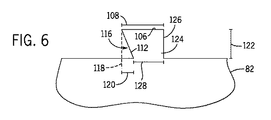
勿論、相対寸法108、110、114、及び120、並びにロータランド96の幾何形状は、単に例証として定められており、限定を意図するものではない。例えば、凹部116の各々の深さ120は、互いに異なっていてもよい。別の実施例では、幅108及び114の相対寸法は変えることができる。更に、凹部116は、側部112の一方又は両方を含めることができる。更に、凹部116は、とりわけ、山形、矩形、方形、長円、湾曲、半円、又は三日月など、他の幾何形状を有することができる。従って、図6〜9は、異なるタイプの凹部を利用したロータランドの他の実施形態を示している。しかしながら、任意の好適な凹部形状をロータランド96の1つ又は両方の側部112に利用することができる。更に、側部112は、同じか、或いは異なるタイプの凹部を有することができる。
Of course, the
図6は、1つの凹部116がロータランド124の上流側部112に配置されたロータランド124を図示している。側部112は、ロータランド124の軸方向中心に向かって延びて凹部116を形成し、対向する側部126は、半径方向表面106に略垂直に延びて比較的直線状の側部126を形成する。半径方向の内側寸法又は幅128は、半径方向表面106の幅よりも小さくすることができる。
FIG. 6 illustrates the
図7は、1つの凹部116がロータランド130の下流側部112に配置されたロータランド130を図示している。図6に示すロータランド124と同様に、凹部116は、内側半径方向寸法又は幅128が半径方向表面106の幅108よりも小さくなるように、幅128を縮小することができる。但しこの実施形態では、凹部116は、ロータランドの下流側部112に配置することができ、対向する直線状側部126は、上流側部126に配置することができる。
FIG. 7 illustrates the
図8は、互いに向かって収束して半円状凹部134(例えば、凹形、C字形、又はU字形)を形成する湾曲した側部132を備えたロータランド131を図示する。各凹部134は、より大きい方の寸法又は深さ136でロータランド131の軸方向中心に向かって収束することができる。特定の実施形態によれば、深さ136は、半径方向表面106の幅108の少なくとも約1、5、10、15、20、30、40、又は50パーセントとすることができる。より正確には、深さ136は、幅108の少なくとも約20パーセントとすることができる。凹部134は、互いに向かって収束して、ロータランド131のより小さい寸法又は幅137を形成することができる。幅137は、表面98と半径方向表面106との間の半径方向の何れかの位置に配置することができる。特定の実施形態において、幅137は、幅108よりも少なくとも約1、5、10、20、30、40、50、60、70、80、又は90パーセント小さくすることができる。更に、幅137は、表面98と比較的同じ半径方向位置に配置されたロータランド131の幅138よりも小さくすることができる。幅138は、幅108と実質的に等しくすることができ、或いは、幅108よりも大きいか、又は小さくてもよい。
FIG. 8 illustrates a
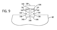
図9は、互いに向かい且つロータランド140の軸方向中心に向かって延びた側部141を有するロータランド140を図示している。略平行な側部142が側部141に略垂直に延びて、矩形凹部144を形成している。側部141及び142は、T字形ロータランド140を形成することができる。各凹部144は深さ146を有することができる。特定の実施形態によれば、深さ146は、半径方向表面106の幅108の少なくとも約1、5、10、15、20、30、40、又は50パーセントとすることができる。より正確には、深さ146は、幅108の少なくとも約20パーセントとすることができる。凹部144は、互いに向かって延びて、ロータランド140のより小さい寸法又は幅148を形成することができる。幅148は、表面98により略定められる、軸線72(図2)の回りの半径方向位置に配置することができる。更に、幅148は、一般に、幅108よりも小さくすることができる。例えば、幅146は、幅108よりも少なくとも約1、5、10、20、30、40、50、60、70、80、又は90パーセント小さくすることができる。
FIG. 9 illustrates the rotor lands 140 having
ロータランド96、124、130、131、及び140は、パッケージシール86を流れる流体のより多くの運動エネルギーを圧力エネルギーに変換し、これにより漏洩を最小限にしてシールを向上させるように設計することができる。具体的には、ロータランド96、124、130、131、及び140の各々は、チャンバ100(図3)のサイズを増大させるように設計された凹部116、134、及び144を含むことができる。凹部116、134、及び144はまた、流体流の再循環及び/又は旋回を誘起し、これによりロータランド96、124、130、131、及び141とシール歯状部94との間の界接部に向かう直接流を低減可能になることによって、各ロータランド96、124、130、131、及び140の各々の上流側及び/又は下流側の圧力分布を改善することができる。
The rotor lands 96, 124, 130, 131, and 140 are designed to convert more kinetic energy of the fluid flowing through the
更に、ロータランドの相対形状、寸法、及びサイズは変わることができる。例えば、湾曲側部(図8)は、ロータランドの一方の側部に配置することができ、直線状側部(図7)、角度付き側部(図5)、又は矩形側部141及び142(図9)は、ロータランドの反対の側部に配置される。更に、ロータランド及び/又は凹部の相対高さ、幅、及び深さは変わることができる。更に、特定の高さ、幅、深さ、及び/又はロータランドとシール歯状部との間の間隙は、回転機械のサイズなどの要因に応じて変わることができる。凹部の任意の好適な幾何形状及び/又は組み合わせを利用して、チャンバ100(図3)の少なくとも1つの容積を増大させ、及び/又は流体の再循環、スワール及び/又は反転流を誘起するよう設計された凹状部をロータランドに提供することができる。
Further, the relative shape, dimensions, and size of the rotor land can vary. For example, the curved side (FIG. 8) can be placed on one side of the rotorland and can be a straight side (FIG. 7), an angled side (FIG. 5), or
本明細書は、最良の形態を含む実施例を用いて本発明を開示し、更に、あらゆる当業者があらゆるデバイス又はシステムを実施及び利用すること並びにあらゆる包含の方法を実施することを含む本発明を実施することを可能にする。本発明の特許保護される範囲は、請求項によって定義され、当業者であれば想起される他の実施例を含むことができる。このような他の実施例は、請求項の文言と差違のない構造要素を有する場合、或いは、請求項の文言と僅かな差違を有する均等な構造要素を含む場合には、本発明の範囲内にあるものとする。 This written description discloses the invention using examples, including the best mode, and further includes any person skilled in the art to make and use any device or system and any method of inclusion. It is possible to carry out. The patentable scope of the invention is defined by the claims, and may include other examples that occur to those skilled in the art. Such other embodiments are within the scope of the invention if they have structural elements that do not differ from the words of the claims, or if they contain equivalent structural elements that have slight differences from the words of the claims. It shall be in
2 複合サイクルシステム
4 ガスタービン
6 蒸気タービン
8 HRSGシステム
14 第1の負荷
16 タービン
18 燃焼器
20 圧縮機
24 第2の負荷
26 低圧セクション
28 中圧セクション
30 高圧セクション
34 排出ガス
36 凝縮器
38 復水ポンプ
40 低圧エコノマイザ
42 低圧エコノマイザ
44 中圧エコノマイザ
46 中圧蒸発器
48 高圧エコノマイザ
50 高圧蒸発器
52 高圧過熱器
54 最終高圧過熱器
56 段間過熱低減器
58 1次再熱器
60 2次再熱器
62 段間過熱低減器
64 主蒸気入口ポート
66 HPブレード
70 HPシャフト
72 軸線
73 ブレード
74 クロスオーバ管体
76 ノズルボックス
78 ブレード
82 IPシャフト
83 フランジ
84 パッキングケーシング
86 パッキングシール
88 パッキングリング
89 軸方向
90 シールセグメント
91 半径方向
92 シール表面
94 シール歯状部
96 ロータランド
97 界接位置
98 表面
99 界接位置
100 チャンバ
102 矢印
103 反転流
104 旋回流
106 半径方向表面
108 幅
110 間隙
112 側部
114 幅
116 凹部
118 破線
120 深さ
122 高さ
124 ロータランド
126 側部
128 幅
130 ロータランド
131 ロータランド
132 側部
134 凹部
136 深さ
138 幅
140 ロータランド
142 側部
144 凹部
146 幅
148 深さ
2 Combined cycle system 4
Claims (9)
前記回転機械(6)の回転部品(70、82)及び固定部品(84)間に配置されたパッキングシール(86)と
を備えたシステム(2)であって、前記パッキングシール(86)が、前記回転部品(70、82)の回転軸線に沿って互いに間隔を置いて配置された第1の軸方向(89)位置に配置される複数の歯状部(94)と、前記複数の歯状部(94)と半径方向に整列して第1の軸方向(89)位置に配置された複数のランド(96)とを含んでおり、前記ランド(96)が各々、前記回転軸線に対して互いに対向する第1及び第2の軸方向側部(112)と、第1の側部(112)又は第2の側部(112)、或いは両方(112)にある凹部(116)とを含んでいて、前記凹部(116)が略三角形の凹部を含む、システム(2)。 Rotating machines (6, 16, 20);
Said rotation A machine (6) rotating parts (70,82) and a fixed part (84) system comprising arranged between the <br/> packing seals (86) between (2), the packing seals ( 86) a plurality of teeth (94) disposed at first axial (89) positions spaced apart from each other along the rotational axis of the rotating component (70, 82); Including a plurality of teeth (94) and a plurality of lands (96) radially aligned and disposed at a first axial (89) position, wherein each of said lands (96) is said rotating The first and second axial side portions (112) facing each other with respect to the axis and the concave portion (116) on the first side portion (112) or the second side portion (112) or both (112). And the recess (116) includes a substantially triangular recess. (2).
前記環状ランド(96)が、第1の半径位置から第2の半径位置にある半径方向表面(106)に延びる半径方向突出部(96、129、130、131、140)を含み、前記半径方向表面(106)が、前記パッキングリング(88)と整列するように構成され、前記半径方向突出部が、第1及び第2の半径位置の間に第1の軸方向寸法(114、128、131、148)を有し、前記半径方向突出部が、第2の半径位置に第2の軸方向寸法(108)を有し、第1の軸方向寸法(114、128、131、148)が、第2の軸方向寸法(108)よりも少なくとも20パーセント小さく、前記半径方向突出部が略三角形の突出部(124、130)を含んでいる、システム。 A system (2) comprising a rotor comprising an annular land (96) configured to align with a packing ring (88) of a turbine engine (6), comprising:
The annular land (96) includes a radial protrusion (96, 129, 130, 131, 140) extending from a first radial position to a radial surface (106) at a second radial position, the radial direction A surface (106) is configured to be aligned with the packing ring (88), and the radial protrusion is a first axial dimension (114, 128, 131) between first and second radial positions. 148), the radial protrusion has a second axial dimension (108) at a second radial position, and the first axial dimension (114, 128, 131, 148) is the second axial dimension (108) at least 20 percent rather smaller than the radial projection contains protrusions of the substantially triangular (124 and 130), system.
10. A system according to any one of claims 7 or 9 , wherein the radial protrusions extend radially outward from a rotor toward the packing ring.
Applications Claiming Priority (2)
| Application Number | Priority Date | Filing Date | Title |
|---|---|---|---|
| US12/432,272 US8206082B2 (en) | 2009-04-29 | 2009-04-29 | Packing seal rotor lands |
| US12/432,272 | 2009-04-29 |
Publications (3)
| Publication Number | Publication Date |
|---|---|
| JP2010261441A JP2010261441A (en) | 2010-11-18 |
| JP2010261441A5 JP2010261441A5 (en) | 2013-06-06 |
| JP5725727B2 true JP5725727B2 (en) | 2015-05-27 |
Family
ID=42200024
Family Applications (1)
| Application Number | Title | Priority Date | Filing Date |
|---|---|---|---|
| JP2010098367A Expired - Fee Related JP5725727B2 (en) | 2009-04-29 | 2010-04-22 | Packing seal rotaland |
Country Status (4)
| Country | Link |
|---|---|
| US (1) | US8206082B2 (en) |
| EP (1) | EP2246598B1 (en) |
| JP (1) | JP5725727B2 (en) |
| RU (1) | RU2535589C2 (en) |
Cited By (1)
| Publication number | Priority date | Publication date | Assignee | Title |
|---|---|---|---|---|
| JP7378353B2 (en) | 2020-06-04 | 2023-11-13 | 能美防災株式会社 | Fire extinguishing equipment |
Families Citing this family (8)
| Publication number | Priority date | Publication date | Assignee | Title |
|---|---|---|---|---|
| US8317465B2 (en) * | 2009-07-02 | 2012-11-27 | General Electric Company | Systems and apparatus relating to turbine engines and seals for turbine engines |
| JP5558138B2 (en) * | 2010-02-25 | 2014-07-23 | 三菱重工業株式会社 | Turbine |
| US8807927B2 (en) * | 2011-09-29 | 2014-08-19 | General Electric Company | Clearance flow control assembly having rail member |
| US20140054863A1 (en) * | 2012-08-21 | 2014-02-27 | General Electric Company | Seal assembly for a turbine system |
| JP5936515B2 (en) * | 2012-10-18 | 2016-06-22 | 三菱日立パワーシステムズ株式会社 | Rotating machine |
| JP6209199B2 (en) | 2015-12-09 | 2017-10-04 | 三菱日立パワーシステムズ株式会社 | Seal fin, seal structure, turbomachine and method of manufacturing seal fin |
| JP2017145813A (en) * | 2016-02-19 | 2017-08-24 | 三菱日立パワーシステムズ株式会社 | Rotary machine |
| FR3050250B1 (en) * | 2016-04-15 | 2018-04-13 | Safran Transmission Systems | NON-CONTACT SEAL OF LABYRINTH TYPE OBTAINED BY ADDITIVE MANUFACTURE |
Family Cites Families (17)
| Publication number | Priority date | Publication date | Assignee | Title |
|---|---|---|---|---|
| US1848613A (en) | 1932-03-08 | House electric | ||
| US1831242A (en) | 1926-12-09 | 1931-11-10 | Westinghouse Electric & Mfg Co | Labyrinth packing |
| CH316889A (en) | 1953-12-30 | 1956-10-31 | Sulzer Ag | poetry |
| JPS58127258U (en) * | 1982-02-22 | 1983-08-29 | 三菱重工業株式会社 | labyrinth seal |
| SU1182224A1 (en) * | 1984-04-05 | 1985-09-30 | Предприятие П/Я Р-6977 | Shaft labyrinth packing |
| SU1576755A1 (en) * | 1988-06-15 | 1990-07-07 | Тернопольский Филиал Львовского Политехнического Института | Labyrinth packing |
| US5029876A (en) | 1988-12-14 | 1991-07-09 | General Electric Company | Labyrinth seal system |
| JPH1151200A (en) * | 1997-08-06 | 1999-02-23 | Mitsubishi Heavy Ind Ltd | Labyrinth seal |
| US6168377B1 (en) | 1999-01-27 | 2001-01-02 | General Electric Co. | Method and apparatus for eliminating thermal bowing of steam turbine rotors |
| US6394459B1 (en) * | 2000-06-16 | 2002-05-28 | General Electric Company | Multi-clearance labyrinth seal design and related process |
| JP4371610B2 (en) * | 2001-05-30 | 2009-11-25 | 株式会社東芝 | Steam turbine sealing equipment |
| US6854735B2 (en) | 2002-08-26 | 2005-02-15 | General Electric Company | In situ load sharing brush seals |
| US7094029B2 (en) | 2003-05-06 | 2006-08-22 | General Electric Company | Methods and apparatus for controlling gas turbine engine rotor tip clearances |
| JP4468060B2 (en) * | 2003-05-09 | 2010-05-26 | 三菱重工業株式会社 | High temperature water pump shaft seal device |
| US7500396B2 (en) | 2005-10-20 | 2009-03-10 | General Electric Company | Phased array ultrasonic methods and systems for generator rotor teeth inspection |
| US20110250073A1 (en) * | 2010-04-08 | 2011-10-13 | Sudhakar Neeli | Rotor and assembly for reducing leakage flow |
| US20110280715A1 (en) * | 2010-05-11 | 2011-11-17 | General Electric Company | Curved labyrinth seals |
-
2009
- 2009-04-29 US US12/432,272 patent/US8206082B2/en active Active
-
2010
- 2010-04-22 JP JP2010098367A patent/JP5725727B2/en not_active Expired - Fee Related
- 2010-04-28 RU RU2010116686/06A patent/RU2535589C2/en active
- 2010-04-29 EP EP10161433A patent/EP2246598B1/en not_active Not-in-force
Cited By (1)
| Publication number | Priority date | Publication date | Assignee | Title |
|---|---|---|---|---|
| JP7378353B2 (en) | 2020-06-04 | 2023-11-13 | 能美防災株式会社 | Fire extinguishing equipment |
Also Published As
| Publication number | Publication date |
|---|---|
| EP2246598B1 (en) | 2013-03-20 |
| EP2246598A1 (en) | 2010-11-03 |
| US20100276892A1 (en) | 2010-11-04 |
| RU2010116686A (en) | 2011-11-10 |
| JP2010261441A (en) | 2010-11-18 |
| RU2535589C2 (en) | 2014-12-20 |
| US8206082B2 (en) | 2012-06-26 |
Similar Documents
| Publication | Publication Date | Title |
|---|---|---|
| JP5725727B2 (en) | Packing seal rotaland | |
| US20110280715A1 (en) | Curved labyrinth seals | |
| JP6186133B2 (en) | Overlapping seals for turbine system transition ducts | |
| JP5865798B2 (en) | Turbine sealing device and thermal power generation system | |
| US20100071342A1 (en) | Integrated gas turbine exhaust diffuser and heat recovery steam generation system | |
| US20130283817A1 (en) | Flexible seal for transition duct in turbine system | |
| JP2014132211A (en) | Articulated transition duct in turbomachine, where this invention was made with government support under contract number de-fc26-05nt42643 awarded by department of energy and government has certain rights in this invention | |
| EP2592233B1 (en) | Turbine system comprising a convolution seal | |
| US20150240667A1 (en) | Exhaust plenum for radial diffuser | |
| US10677072B2 (en) | Bucket vibration damping structure and bucket and turbomachine having the same | |
| KR20150080911A (en) | Steam turbine and methods of assembling the same | |
| US8899909B2 (en) | Systems and methods for steam turbine wheel space cooling | |
| KR102467399B1 (en) | Steam turbine plant and combined cycle plant | |
| JP2009191850A (en) | Steam turbine engine and method of assembling the same | |
| KR102256876B1 (en) | Axially faced seal system | |
| US20160281518A1 (en) | Turbine intrusion loss reduction system | |
| JP4413732B2 (en) | Steam turbine plant | |
| US11352912B2 (en) | Steam turbine facility and combined cycle plant | |
| JP5909081B2 (en) | Turbomachine sealing assembly and method for assembling the same | |
| JP6057796B2 (en) | Gas turbine combined plant and method for cooling high temperature components in gas turbine | |
| KR20230045873A (en) | Sealing assembly and turbo-machine comprising the same |
Legal Events
| Date | Code | Title | Description |
|---|---|---|---|
| A521 | Request for written amendment filed |
Free format text: JAPANESE INTERMEDIATE CODE: A523 Effective date: 20130418 |
|
| A621 | Written request for application examination |
Free format text: JAPANESE INTERMEDIATE CODE: A621 Effective date: 20130418 |
|
| A131 | Notification of reasons for refusal |
Free format text: JAPANESE INTERMEDIATE CODE: A131 Effective date: 20140218 |
|
| A601 | Written request for extension of time |
Free format text: JAPANESE INTERMEDIATE CODE: A601 Effective date: 20140516 |
|
| A602 | Written permission of extension of time |
Free format text: JAPANESE INTERMEDIATE CODE: A602 Effective date: 20140521 |
|
| A601 | Written request for extension of time |
Free format text: JAPANESE INTERMEDIATE CODE: A601 Effective date: 20140617 |
|
| A602 | Written permission of extension of time |
Free format text: JAPANESE INTERMEDIATE CODE: A602 Effective date: 20140620 |
|
| A601 | Written request for extension of time |
Free format text: JAPANESE INTERMEDIATE CODE: A601 Effective date: 20140717 |
|
| A602 | Written permission of extension of time |
Free format text: JAPANESE INTERMEDIATE CODE: A602 Effective date: 20140723 |
|
| A521 | Request for written amendment filed |
Free format text: JAPANESE INTERMEDIATE CODE: A523 Effective date: 20140818 |
|
| TRDD | Decision of grant or rejection written | ||
| A01 | Written decision to grant a patent or to grant a registration (utility model) |
Free format text: JAPANESE INTERMEDIATE CODE: A01 Effective date: 20150303 |
|
| A61 | First payment of annual fees (during grant procedure) |
Free format text: JAPANESE INTERMEDIATE CODE: A61 Effective date: 20150331 |
|
| R150 | Certificate of patent or registration of utility model |
Ref document number: 5725727 Country of ref document: JP Free format text: JAPANESE INTERMEDIATE CODE: R150 |
|
| R250 | Receipt of annual fees |
Free format text: JAPANESE INTERMEDIATE CODE: R250 |
|
| R250 | Receipt of annual fees |
Free format text: JAPANESE INTERMEDIATE CODE: R250 |
|
| R250 | Receipt of annual fees |
Free format text: JAPANESE INTERMEDIATE CODE: R250 |
|
| R250 | Receipt of annual fees |
Free format text: JAPANESE INTERMEDIATE CODE: R250 |
|
| LAPS | Cancellation because of no payment of annual fees |