JP5724634B2 - Nail printing apparatus and printing control method - Google Patents
Nail printing apparatus and printing control method Download PDFInfo
- Publication number
- JP5724634B2 JP5724634B2 JP2011117564A JP2011117564A JP5724634B2 JP 5724634 B2 JP5724634 B2 JP 5724634B2 JP 2011117564 A JP2011117564 A JP 2011117564A JP 2011117564 A JP2011117564 A JP 2011117564A JP 5724634 B2 JP5724634 B2 JP 5724634B2
- Authority
- JP
- Japan
- Prior art keywords
- finger
- printing
- output
- nail
- Prior art date
- Legal status (The legal status is an assumption and is not a legal conclusion. Google has not performed a legal analysis and makes no representation as to the accuracy of the status listed.)
- Active
Links
Images


Description
本発明は、ネイルプリント装置および印刷制御方法に関するものである。 The present invention relates to a nail printing apparatus and a printing control method.
ネイルプリント装置は、印刷しようとする爪の指である印刷指を、装置本体に設けた載置台上に載置し、この印刷指の爪部に印刷するプリント装置である。
しかし、印刷指を載置台上に載せただけの場合には、手が不安定な状態にあるため、手や腕の動きが印刷指に伝わり、印刷指が動いてしまう虞がある。印刷中に印刷指が動いて位置がずれると絵柄等を正しく爪部に印刷することができず、印刷エラーが生じてしまう。
The nail printing apparatus is a printing apparatus in which a printing finger, which is a nail finger to be printed, is placed on a placing table provided in the apparatus body and printed on a nail portion of the printing finger.
However, when the printing finger is simply placed on the mounting table, the hand is in an unstable state, so that the movement of the hand or arm is transmitted to the printing finger, and the printing finger may move. If the printing finger moves and the position is shifted during printing, the pattern or the like cannot be printed correctly on the nail portion, and a printing error occurs.
また、例えばインクジェット方式で印刷を行う場合、印刷手段の印刷ヘッドと爪部との間の位置(距離)が離れすぎると正確な位置にインクが着弾せず絵柄等を精緻に印刷できず、逆に位置(距離)が近づきすぎると爪や指と印刷ヘッドとが接触して、爪部や指が汚れたり、印刷ヘッドが破損する虞を生じる。
このため、ネイルプリント装置においては、指爪及び印刷ヘッドの双方を保護し、かつ精緻な印刷が可能な位置関係(距離等)となるように、印刷指を適切な位置に位置決め固定する必要がある。
In addition, for example, when printing by an inkjet method, if the position (distance) between the print head of the printing means and the nail part is too far away, the ink will not land at the correct position and the pattern or the like cannot be printed precisely, and the reverse If the position (distance) is too close to the nail, the nail or finger and the print head come into contact with each other, which may cause the nail or finger to become dirty or the print head to be damaged.
For this reason, in the nail printing apparatus, it is necessary to position and fix the printing finger at an appropriate position so that both the fingernail and the print head are protected and the positional relationship (distance, etc.) enables precise printing. is there.
そこで、従来、ネイルプリント装置において、印刷指が動かないように、装置固定の指置き場に印刷指を置き、ホルダ等の拘束具によって印刷指を固定するものが知られている(例えば、特許文献1)。 Therefore, conventionally, in a nail printing apparatus, a printing finger is placed on a finger fixing place fixed to the apparatus so that the printing finger does not move, and the printing finger is fixed by a restraining tool such as a holder (for example, Patent Documents). 1).
しかしながら、印刷を行う間、ホルダ等の拘束具によって指を固定した状態で印刷を行うと、印刷している間、指が圧迫された状態となることから、ユーザにとって極めて不快である。また、爪部に対して印刷する際に、事前に拘束具を指に固定して装置内にセットするという作業が必要となるため、印刷前の準備に手間がかかってしまう。
このため、特に女性ユーザがおしゃれや身だしなみの一環として用いるネイルプリント装置において、手軽に印刷を行うことができず、ユーザが装置の使用を敬遠しがちになるという問題がある。
また、このような拘束具を備えると、ネイルプリント装置自体も大型化してしまうという問題もある。
However, if printing is performed with a finger fixed by a restraining tool such as a holder during printing, the finger is pressed during printing, which is extremely uncomfortable for the user. Further, when printing on the nail portion, it is necessary to fix the restraining tool to the finger in advance and set it in the apparatus, so that it takes time to prepare for printing.
For this reason, particularly in a nail print apparatus that is used by female users as a part of fashion and appearance, there is a problem that printing cannot be performed easily and the user tends to avoid using the apparatus.
Further, when such a restraining tool is provided, there is a problem that the nail printing apparatus itself is also increased in size.
本発明は以上のような事情に鑑みてなされたものであり、拘束具を用いることなく、簡易な手法により印刷指をセットして、爪部への精緻な印刷を行うことのできるネイルプリント装置および印刷制御方法を提供することを目的とするものである。 The present invention has been made in view of the circumstances as described above, and is a nail printing apparatus capable of performing precise printing on a nail portion by setting a printing finger by a simple method without using a restraining tool. It is another object of the present invention to provide a printing control method.
前記課題を解決するために、請求項1に記載のネイルプリント装置は、
印刷しようとする爪部に対応する指である印刷指を載置する印刷指載置手段と、
この印刷指載置手段に載置されている印刷指の爪部に印刷を施す印刷ヘッドを有する印刷手段と、
前記印刷指載置手段に設けられ、前記印刷指載置手段に前記印刷指が載置された際に、指検出信号を出力し、前記印刷指が前記印刷指載置手段から離れた際に、指非検出信号を出力する指載置検出手段と、
前記印刷指載置手段に載置されている前記印刷指の位置を検出する印刷指検出手段と、
前記指載置検出手段から前記指検出信号が出力されたとき、前記指検出信号の信号出力時又はこの信号出力時から所定の時間経過後に前記印刷手段により前記爪部に対して印刷を施す印刷動作を開始させ、前記印刷動作中に、前記指載置検出手段から前記指非検出信号が出力されたとき、前記印刷動作を停止させるとともに、前記印刷指検出手段によって検出された前記印刷指の位置に応じて、前記印刷指から離れる方向に前記印刷ヘッドを移動させように、前記印刷手段を制御する印刷制御手段と、
を備えていることを特徴としている。
In order to solve the problem, the nail printing apparatus according to
A print finger placement means for placing a print finger that is a finger corresponding to the nail portion to be printed;
A printing means having a print head for printing on the nail portion of the printing finger placed on the printing finger placement means;
When the printing finger is placed on the printing finger placement unit, the finger detection signal is output when the printing finger is placed on the printing finger placement unit, and when the printing finger is separated from the printing finger placement unit. Finger placement detection means for outputting a finger non-detection signal;
Printing finger detection means for detecting the position of the printing finger placed on the printing finger placement means;
When the finger detecting signal is output from the finger placing置検detecting means, printing to perform printing on the nail portion by the printing means from the time the signal output or when the signal output of the finger detection signal after a predetermined time has elapsed When the finger placement detection unit outputs the finger non-detection signal during the printing operation, the printing operation is stopped and the printing finger detected by the printing finger detection unit is started. depending on the position, so moving the print head in a direction away from the printing finger, and print control means for controlling said printing means,
It is characterized by having.
本発明によれば、印刷指を載置する印刷指載置手段に設けられた指載置検出手段から印刷指載置手段に印刷指が載置されていることを示す指検出信号が出力されると、指検出信号の信号出力時又はこの信号出力時から所定の時間経過後に印刷指の爪部に対して印刷手段による印刷動作を開始させることができ、印刷動作中に指載置検出手段から、印刷指載置手段から印刷指が離れたことを示す指非検出信号が出力されると、印刷手段による爪部への印刷動作を停止させるとともに、印刷指から離れる方向に印刷手段の印刷ヘッドを移動させることができる。
このため、拘束具等により印刷指を固定しなくても、印刷指が浮き上がりを生じる等印刷に不適な状態のままで印刷が行われることがなく、簡易な手法で爪部への精緻な印刷を行うことができる。
According to the present invention, a finger detection signal indicating that the printing finger is placed on the printing finger placement means is output from the finger placement detection means provided in the printing finger placement means for placing the printing finger. Then, when the finger detection signal is output or after a predetermined time has elapsed since the signal output, the printing operation by the printing unit can be started with respect to the nail portion of the printing finger, and the finger placement detection unit can be started during the printing operation. When a finger non-detection signal indicating that the printing finger is separated from the printing finger placement unit is output, the printing unit stops the printing operation on the nail portion and the printing unit prints away from the printing finger. The head can be moved .
For this reason, even if the printing finger is not fixed with a restraint or the like, the printing finger is lifted up and remains in an unsuitable state for printing. It can be performed.
[第1の実施形態]
まず、図1から図13を参照しつつ、本発明に係るネイルプリント装置および印刷制御方法の第1の実施形態について説明する。なお、本発明の範囲は図示例に限定されない。
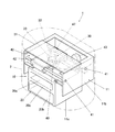
図1は、本実施形態におけるネイルプリント装置の外観を示す斜視図であり、図2は、ネイルプリント装置の内部構成を示す斜視図である。
[First Embodiment]
First, a first embodiment of a nail printing apparatus and a printing control method according to the present invention will be described with reference to FIGS. The scope of the present invention is not limited to the illustrated example.
FIG. 1 is a perspective view illustrating an appearance of a nail print apparatus according to the present embodiment, and FIG. 2 is a perspective view illustrating an internal configuration of the nail print apparatus.
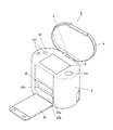
図1に示すように、このネイルプリント装置1は、ケース本体2及び蓋体4を備えている。このケース本体2及び蓋体4は、ケース本体2の上面後端部に設けたヒンジ3を介して、互いに連結されている。
As shown in FIG. 1, the
上記ケース本体2は平面視で長円状に形成されている。このケース本体2には前側には開閉板2cが起倒可能に設けられている。この開閉板2cは、ケース本体2の前面下端部に設けたヒンジ(図示せず)を介して、ケース本体2に連結されている。この開閉板2cは、ケース本体2の前面を開閉するためのものである。
また、ケース本体2の天板2fには後述する操作部12が設置されており、天板2fのほぼ中央部には表示部13が設定されている。
なお、ケース本体2及び蓋体4の形状、構成はここに例示したものに限定されない。
The
An
Note that the shapes and configurations of the
また、ケース本体2にはネイルプリント装置1の装置本体10が収容されている。この装置本体10は、図2に示す印刷指固定手段を構成している印刷指固定部20、撮影手段を構成している撮影部30、印刷手段を構成している印刷部40及び制御手段を構成している制御部50(図7参照)を備えている。これら印刷指固定部20、撮影部30、印刷部40及び制御部50は機枠11に設けられている。
なお、機枠11は下部機枠11a及び上部機枠11bによって構成されている。そして、下部機枠11aは箱状に形成され、ケース本体2の内部下方に設置され、上部機枠11bは下部機枠11aの上方で且つケース本体2の内部上方に設置されている。
Further, the case
The
印刷指固定部20は、機枠11の中の下部機枠11aに設けられている。この下部機枠11aに設けられた印刷指挿入部20a、非印刷指挿入部20b及び掴み部20cによって印刷指固定部20が構成されている。
ここで、印刷指挿入部20aは、印刷しようとする爪部Tに対応する指(以下「印刷指」という。)U1を挿入するめための指挿入部である(図3参照)。印刷指挿入部20aの底面(印刷指載置面21a)は、印刷指U1を載置する印刷指載置手段として機能する。印刷指U1の撮影や印刷は、印刷指U1がこの印刷指載置手段としての印刷指挿入部20aの印刷指載置面21aに載置された状態で行われる。
また、非印刷指挿入部20bは、印刷指以外の指(以下「非印刷指」という。)U2を挿入するための指挿入部である(図3参照)。
また、掴み部20cは、印刷指挿入部20aに挿入された印刷指U1と、非印刷指挿入部20bに挿入された非印刷指U2とで挟持することが可能な部分である。本実施形態において、この掴み部20cは印刷指挿入部20aと非印刷指挿入部20bとを仕切る隔壁21によって構成されている。
The printing
Here, the printing
Further, the non-printing
The gripping
この隔壁21の上面は平坦な印刷指載置面21aを構成している。この隔壁21の指挿入側端部には膨出部22が形成されている。この膨出部22は、印刷指挿入部20a及び非印刷指挿入部20bに印刷指U1及び非印刷指U2を深く挿入した際に、印刷指U1及び非印刷指U2の付け根U3が当接する部分に形成されている。膨出部22は、印刷指U1の腹全体が印刷指載置面21aに当接した状態で、印刷指U1と非印刷指U2とで隔壁21(掴み部20c)を強く挟持することができるように、指挿入方向Xの断面が、隔壁21の下面から下方に向けて膨出するように円形となっている。なお、膨出部22の形状は、断面円形に限定されることなく、断面楕円形,多角形等の非円形であってもよい。
The upper surface of the
例えば、左手の親指以外の4本の指(人差し指、中指、薬指及び小指)が印刷指U1となる場合には、図3に示すように、ユーザは印刷指挿入部20aに4本の印刷指U1を挿入し、非印刷指挿入部20bに非印刷指U2である親指を挿入する。この場合、ユーザが印刷指挿入部20aに挿入された印刷指U1と、非印刷指挿入部20bに挿入された非印刷指U2とで掴み部20cを挟持することにより、印刷指U1が掴み部20cの上で固定される。
また、親指のみが印刷指U1となる場合には、親指(印刷指U1)を印刷指挿入部20aに挿入さし、親指以外の4本の指(非印刷指U2)を非印刷指挿入部20bに挿入する。この場合にも、ユーザが印刷指U1と非印刷指U2とで掴み部20cを挟持することで印刷指U1が固定される。
For example, when four fingers (index finger, middle finger, ring finger, and little finger) other than the thumb of the left hand are the print fingers U1, the user places four print fingers on the print
When only the thumb becomes the printing finger U1, the thumb (printing finger U1) is inserted into the printing
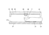
図4は、印刷指載置面21a上に左手の親指以外の4本の指(人差し指、中指、薬指及び小指)が印刷指U1として載置されている状態を示した斜視図であり、図5は、図4に示す印刷指載置面21aの平面図であり、図6は、図5のVI-VI線に沿う断面図である。
図4から図6に示すように、本実施形態では、印刷指載置手段である印刷指載置面21aを構成している隔壁21の上側の面であって、後述する印刷ヘッド46の印刷可能領域23内には、印刷指載置面21aに印刷指U1が載置されると印刷指U1によって押圧されることにより指検出信号を出力し、印刷指U1が離れることにより指非検出信号を出力する指載置検出手段としてのプッシュスイッチ24が設けられている。プッシュスイッチ24から出力された指検出信号、指非検出信号は、後述する制御部50の印刷制御部53(図9参照)に送られるようになっている。
本実施形態では、人差し指から小指までの4本を同時に印刷指U1として印刷指挿入部20aに挿入して印刷を行うことも、また、両手の親指から小指までの10本のうち、1本以上(例えば両手の親指同士2本等)を印刷指U1として印刷指挿入部20aに挿入して印刷を行うこともできるようになっている。プッシュスイッチ24は、本実施形態で想定される様々なパターンに対応可能なように、印刷指載置面21a上にほぼ等間隔に4つ設けられている。
FIG. 4 is a perspective view showing a state in which four fingers other than the left thumb (index finger, middle finger, ring finger, and little finger) are placed as printing fingers U1 on the printing finger placement surface 21a. 5 is a plan view of the printing
As shown in FIGS. 4 to 6, in the present embodiment, printing is performed on a
In the present embodiment, printing is performed by simultaneously inserting four fingers from the index finger to the little finger into the printing
図4から図6に示すように、本実施形態では、各プッシュスイッチ24は、印刷指U1となり得る全ての指の先端部から第一関節辺りに対応する範囲内に位置するように配置されている。なお、プッシュスイッチ24は、印刷指載置面21aに印刷指U1が載置されたときに印刷指U1を検出して、指検出信号を出力できる位置に配置されていればよく、プッシュスイッチ24が設けられる位置は図示例に限定されない。
As shown in FIGS. 4 to 6, in the present embodiment, each
また、図7は、本実施形態に係るネイルプリント装置1の正面側の断面図であり、図8は、ネイルプリント装置1の側断面図である。
図7及び図8に示すように、撮影部30は、機枠11の中の上部機枠11bに設けられている。
すなわち、上部機枠11bに設置された基板31の中央部下面には、ドライバーを内蔵した200万画素程度以上の画素を有するカメラ32が設置されている。また、基板31には、カメラ32を囲むように白色LED等の照明灯33が設置されている。撮影部30は、このカメラ32及び照明灯33を備えて構成されている。
この撮影部30は、印刷指載置手段である印刷指載置面21aに載置された印刷指U1を照明灯33によって照明し、カメラ32によってその印刷指U1を撮影して、指爪画像を得る撮影手段であり、この撮影部30は、後述する制御部50の撮影制御部51に接続され、該撮影制御部51によって制御されるようになっている。
また、本実施形態では、撮影部30は、印刷指挿入部20a内を撮影して、印刷指挿入部20a内に挿入されている印刷指U1の数等を検出する手段としても機能する。
撮影部30によって撮影され、取得された指爪画像や印刷指U1の数等の情報は、後述する印刷指記憶部54に記憶される。
7 is a front sectional view of the
As shown in FIGS. 7 and 8, the photographing
That is, a
The photographing
In the present embodiment, the photographing
Information such as the number of fingernail images and printing fingers U1 captured and acquired by the
また、印刷部40は、印刷指載置手段である印刷指載置面21aに載置されている印刷指U1の爪部Tに色や模様等の印刷を施す印刷手段であり、主に上部機枠11bに設けられている。
すなわち、図7及び図8に示すように、上部機枠11bの両側板には、2本のガイドロッド41が平行に架設されている。このガイドロッド41には、主キャリッジ42が摺動自在に設置されている。また、図8に示すように、主キャリッジ42の前壁42aおよび後壁42bには2本のガイドロッド44が平行に架設されている。このガイドロッド44には、副キャリッジ45が摺動自在に設置されている。この副キャリッジ45の下面中央部には、爪部Tに印刷を施す印刷ヘッド46が搭載されている。
The
That is, as shown in FIGS. 7 and 8, two
本実施形態において、この印刷ヘッド46は、インクを微滴化し、被印刷媒体に対し直接に吹き付けて印刷を行うインクジェット方式の印刷ヘッドであり、印刷指U1が載置される印刷指載置面に対向する面にインクを吐出させるノズルが複数設けられたノズル面(図示せず)が形成されている。ノズル面は印刷ヘッド46の印刷指載置面21aに対向する面全体に設けられていてもよいし、印刷ヘッド46の印刷指載置面21aに対向する面の面積よりも小さい範囲に設けられていてもよい。
なお、印刷ヘッド46の記録方式はインクジェット方式に限定されない。本実施形態における印刷ヘッド46は、後述する印刷制御部53がヘッド駆動回路55を介して例えば圧電素子等で構成されているヘッド駆動部461を制御することにより駆動し、微滴化されたインクを吐出させるようになっている。また、指載置検出手段であるプッシュスイッチ24から指非検出信号が出力された場合には、印刷制御部53がヘッド駆動回路55を介してヘッド駆動部461を制御することにより、印刷ヘッド46からのインクの吐出を停止させるようになっている。
In the present embodiment, the
The recording method of the
なお、本実施形態では、指載置検出手段であるプッシュスイッチ24から指非検出信号が出力されると、印刷ヘッド46は、ヘッド移動手段である第1モータ43及び第2モータ47を駆動させることにより、印刷指U1の挿入方向Xの奥側であって印刷指載置面21aに載置されている印刷指U1から離れる方向に移動するようになっている。
In this embodiment, when a finger non-detection signal is output from the
主キャリッジ42は動力伝達手段(図示せず)を介して第1モータ43に連結され、第1モータ43の正逆回転によって、ガイドロッド41に沿って図4における左右方向(指挿入方向Xに直交するY方向)に移動ように構成されている。また、副キャリッジ45は動力伝達手段(図示せず)を介して第2モータ47に連結され、第2モータ47の正逆回転によって、ガイドロッド44に沿って前後方向(指挿入方向X)に移動するように構成されている。
第1モータ43及び第2モータ47は、印刷制御部53がヘッド移動回路56を介して動作を制御することにより、印刷ヘッド46を印刷指U1の挿入方向X及びこれに直交する方向であるY方向に移動させるヘッド移動手段である。
また、下部機枠11aには、印刷ヘッド46にインクを供給するためのインクカートリッジ48が設けられている。インクカートリッジ48は、図示しないインク供給管を介して印刷ヘッド46と接続されており、適宜印刷ヘッド46にインクを供給するようになっている。なお、印刷ヘッド46自体にインクカートリッジを搭載する構成としてもよい。
The
The
Further, the
印刷部40は、これらガイドロッド41、主キャリッジ42、第1モータ43、ガイドロッド44、副キャリッジ45、印刷ヘッド46、第2モータ47及びインクカートリッジ48等を備えて構成されている。この印刷部40の第1モータ43、印刷ヘッド46、第2モータ47は、後述する制御部50の印刷制御部53に接続され、該印刷制御部53によって制御されるようになっている。
本実施形態において、印刷ヘッド46の可動範囲はネイルプリント装置1の印刷可能領域23(図5等参照)内及びその周辺であり、印刷指U1に対する印刷はこの印刷可能領域23内において行われる。また、指非検出信号が出力された際には、前述のように、印刷ヘッド46は印刷可能領域23よりも指挿入方向Xの奥側に移動、退避する。
The
In the present embodiment, the movable range of the
操作部12は、ユーザが各種入力を行うための入力手段である。
操作部12には、例えば、ネイルプリント装置1の電源をONする電源スイッチ釦、動作を停止させる停止スイッチ釦、その他各種の入力を行うための操作釦121が配置されている。
操作部12から入力操作が行われたときには、操作部12から各種操作に応じた信号が出力され、制御部50に送られる。制御部50は、操作部12から出力された信号に基づいて、装置各部を制御する。
The
For example, a power switch button for turning on the power of the
When an input operation is performed from the
表示部13は、例えば液晶パネル(液晶ディスプレイ(LCD:Liquid Crystal Display))等で構成された表示手段である。
なお、表示部13の表面に、タッチパネルが一体的に構成されていてもよい。この場合には、図示しないスタイラスペン等によるタッチ操作により、表示部13の表面をタッチすることによっても各種の入力を行うことができるように構成される。
The
A touch panel may be integrally formed on the surface of the
表示部13には、例えば、印刷指U1を撮影した指爪画像やその中の爪部T、印刷指U1の爪部Tに印刷すべきネイルデザイン、デザイン確認用のサムネイル画像等が表示されるようになっている。
また、本実施形態では、プッシュスイッチ24から指非検出信号が出力されて印刷ヘッド46による印刷動作が中止されたときには、印刷が中止されたその旨が表示部13に表示されるようになっており、表示部13は、爪部Tへの印刷が中止されたことをユーザに報知する報知手段として機能する。なお、報知される内容は、印刷ができないことのみでなくてもよい。例えば印刷指U1を印刷指挿入部20aから引き抜くように促す表示等を表示部13に表示させてもよい。
The
In this embodiment, when the finger non-detection signal is output from the
次に、図9を参照しつつ、本実施形態の制御構成について説明する。図9は、本実施形態における制御構成を示す要部ブロック図である。
制御部50は、例えばケース本体2の上部に配置された制御基板31上等に実装されており、図示しないCPU(Central Processing Unit)、ROM(Read Only Memory)、RAM(Random Access Memory)等を備えるコンピュータである。ROM等の記憶手段には印刷すべきネイルデザイン等のデータや印刷処理を行うための印刷プログラム等の各種プログラムが格納され、制御部50はこれらのプログラムを実行してネイルプリント装置1の各部を制御するようになっている。なお、プログラム等を記憶する記憶手段は、制御部50内のROM、RAMに限定されず、他に記憶手段が設けられていてもよい。
Next, the control configuration of the present embodiment will be described with reference to FIG. FIG. 9 is a principal block diagram showing a control configuration in the present embodiment.
The
制御部50には、操作部12、表示部13、撮影部30、印刷部40、印刷指記憶部54が接続されている。
印刷指記憶部54は、印刷指載置手段である印刷指載置面21aに載置されている印刷指U1の数と、現に印刷中の印刷指U1の種類及び/又は位置を記憶する印刷指記憶手段である。
An
The print
制御部50は、機能的に見た場合、撮影制御部51、表示制御部52、印刷制御部53等を備えている。これら撮影制御部51、表示制御部52、印刷制御部53等としての機能は、CPUとROMに記憶されたプログラムとの共働によって実現される。
The
表示制御部51は、表示手段としての表示部13を制御する表示制御手段である。
本実施形態では、表示制御部51は、表示部13を制御して表示部13に各種の表示を表示させる。本実施形態では、表示制御部51は、例えば前述のようにデザイン確認画面等のほか、印刷指U1の挿入を指示する画面、印刷動作が中止された旨の報知画面、印刷動作が中止された際に印刷指U1を印刷指挿入部20aから引き抜くよう促す指示画面等、各種の指示画面、告知画面等を表示部13に表示させるようになっている。
The
In the present embodiment, the
撮影制御部52は、印刷指挿入部20aに印刷指U1が挿入されると、撮影部30を制御して爪部Tを含む印刷指U1の画像を取得させ、撮影部30により取得された画像を印刷指記憶部54等に記憶させる。
また、本実施形態では、撮影制御部52は、撮影部30によって撮影された画像から、印刷指載置面21aに載置されている印刷指U1の数と、現に印刷中の印刷指U1の種類及び/又は位置を抽出し、これを印刷指記憶部54等に記憶させるようになっている。
When the printing finger U1 is inserted into the printing
In the present embodiment, the
印刷制御部53は、印刷指U1の爪部T上にネイルデザインを印刷するように印刷部40の印刷動作を制御する印刷制御手段である。
すなわち、印刷制御部53は、指載置検出手段であるプッシュスイッチ24から指検出信号が出力されると、信号出力時又はこの信号出力時から所定の時間経過後に爪部Tに対して印刷初期位置から順次印刷を施すように印刷部40を制御して印刷動作を開始させる。
具体的には、ヘッド移動回路56を制御してヘッド移動手段である第1のモータ43、第2のモータ47を駆動させ、適宜印刷ヘッド46を指挿入方向X及びこれに直交する方向Yに移動させるとともに、ヘッド駆動回路55を制御してヘッド駆動部461を動作させることで印刷ヘッド46を駆動させて、ノズルからインクを吐出させるようになっている。
なお、印刷初期位置とは、印刷指載置面21aに載置されている印刷指U1の爪部Tに印刷を行う場合の印刷動作開始位置をいう。印刷初期位置は予めデフォルトで設定されている。例えば、印刷指載置面21aに載置されている印刷指U1の爪部Tのうち、最も左側に位置する爪部Tから順に左上端から右下端に向かって印刷を行う設定となっている場合に、印刷指載置面21aに左手の人差し指から小指の4本の指が載置された場合には、小指の左上端が印刷初期位置となる。
The
That is, when a finger detection signal is output from the
Specifically, the
The initial printing position is a printing operation start position when printing is performed on the nail portion T of the printing finger U1 placed on the printing
また、印刷動作開始後(すなわち印刷動作中)に指載置検出手段であるプッシュスイッチ24から指非検出信号が出力されると、印刷制御部53は、印刷部40による爪部Tへの印刷動作を中止させる。
具体的には、印刷制御部53は、まずヘッド駆動回路55を介してヘッド駆動部461を制御し、印刷ヘッド46からのインクの吐出を停止させる。さらに、印刷制御部53は、前述のように、印刷指記憶部54に記憶されている印刷指載置面21aに載置されている印刷指U1の数と、現に印刷中の印刷指U1の種類及び/又は位置に応じて、印刷指U1の挿入方向Xの奥側であって印刷指U1から離れる方向に印刷ヘッドU1を移動(退避)させる。
なお、現に印刷中の印刷指U1の種類及び/又は位置とは、プッシュスイッチ24から指非検出信号が出力された時点又は指非検出信号の出力を受けて印刷ヘッド46からのインクの吐出を停止させた時点における印刷指U1の種類及び/又は位置である。現に印刷中の印刷指U1の種類及び/又は位置は、印刷制御部53が印刷ヘッド46による印刷進行状況等を随時モニタリングすることによって把握しているものである。なお、本実施形態では、印刷指載置面21aに載置されている印刷指U1のうち、左端に位置する印刷指U1から順に印刷を行い、印刷ヘッド46が何本目の印刷指U1を印刷しているかを印刷制御部53が随時モニタリングする例について説明するが、印刷制御部53が印刷ヘッド46の移動(退避)先を判断する際にモニタリングする印刷進行状況はこれに限定されない。例えば、印刷ヘッド46による印刷位置を座標として把握し、この座標が印刷可能領域23内のどこに位置しているかに応じて印刷ヘッド46を移動(退避)させるようにしてもよい。
Further, when a finger non-detection signal is output from the
Specifically, the
Note that the type and / or position of the printing finger U1 that is currently being printed refers to the time when the finger non-detection signal is output from the
本実施形態において、印刷制御部53は、具体的には、以下のように印刷ヘッド46の移動(退避)先を判断する。
すなわち、例えば図4及び図5に示すように、印刷指記憶部54に記憶されている印刷指載置面21aに載置されている印刷指U1の数が4本であり、現に印刷中の印刷指U1の種類及び/又は位置が、図5に示すように右から2本目である左手の中指であって、第2の印刷可能領域23bに含まれている場合(すなわち、印刷ヘッド46が印刷可能領域23内の右半分である第2の印刷可能領域23bに位置する場合(図5参照において実線及び破線で示す。))には、印刷制御部53は、印刷ヘッド46を指挿入方向Xの右奥側であって印刷可能領域23の外に移動(退避)させる(図5において一点鎖線で示す。)。
また、例えば図10に示すように、印刷指載置面21aに載置されている印刷指U1の数が1本である場合には、印刷制御部53は、印刷ヘッド46を指挿入方向Xの左奥側であって印刷可能領域23の外に移動(退避)させる(図10において一点鎖線で示す。)。
なお、このように印刷指U1の数が1本である場合には、さらに、現に印刷中の印刷指U1の位置が、第1の印刷可能領域23aに含まれているか否かを印刷ヘッド46が現に印刷していた箇所の座標データに基づいて判断してもよい。すなわち、図11に示すように、印刷ヘッド46が現に印刷していた箇所が印刷指U1の爪部Tの中心よりも右側である場合には、印刷ヘッド46を右奥側であって印刷可能領域23の外に移動(退避)させ、爪部Tの中心よりも左側である場合には、印刷ヘッド46を左奥側であって印刷可能領域23の外に移動(退避)させるようにする。
このように印刷ヘッド46を移動させることにより、印刷動作を停止した印刷ヘッド46が、印刷指U1の爪部Tの上を通過するのを極力避けることができ、印刷ヘッド46と爪部Tとの干渉、接触を可能な限り防ぐことができる。
In the present embodiment, the
That is, for example, as shown in FIGS. 4 and 5, the number of printing fingers U1 placed on the printing
For example, as shown in FIG. 10, when the number of the print fingers U1 placed on the print
When the number of printing fingers U1 is one as described above, it is further determined whether or not the position of the printing finger U1 currently being printed is included in the first
By moving the
次に、図12及び図13を参照しつつ、本実施形態におけるネイルプリント装置1による印刷制御方法について説明する。
このネイルプリント装置1により印刷を行う場合、ユーザはまず、電源スイッチを入れて制御部50を起動させ、印刷指U1に印刷したいネイルデザインを選択する。選択されたネイルデザインは、表示部13に、デザイン確認用のサムネイル画像として表示され、このデザインでよい場合には、ユーザは図示しない確定ボタンでネイルデザインを確定させる。
Next, a printing control method by the
When printing is performed by the
ネイルデザインが確定すると、表示制御部52は、表示部13に、印刷指U1を印刷指載置面に載置するよう促す指示を表示させる(ステップS1)。すなわち、例えば、「所定位置まで指を挿入して印刷指載置面上に指を置いてください」等の文字が表示部13に表示される。撮影制御部51は、撮影部30を制御して印刷指挿入部20a内を撮影させ(ステップS2)、制御部50は、撮影部30により撮影された映像に基づいて印刷指挿入部20a内に何本の印刷指U1が挿入されているかを検出する(ステップS3)。検出された印刷指U1の本数は、印刷指記憶部54に記憶される(ステップS4)。
When the nail design is finalized, the
印刷制御部53は、印刷指記憶部54に記憶された印刷指U1の本数に対応する数のプッシュスイッチ24から指検出信号が出力されたか否かを常に判断し(ステップS5)、印刷指U1の本数に対応する数のプッシュスイッチ24から指検出信号が出力されていないと判断した場合(ステップS5;NO)には、全てのプッシュスイッチ24から指検出信号が出力されるまでステップS5の判断を繰り返す。
他方、印刷指U1の本数に対応する数のプッシュスイッチ24から指検出信号が出力されたと判断した場合(ステップS5;YES)には、印刷部40を制御して、信号出力時又はこの信号出力時から所定の時間経過後に爪部Tに対して印刷初期位置から順次印刷を施す印刷動作を開始させる(ステップS6)。具体的には、例えば、印刷指記憶部54に記憶されている印刷指U1の本数が4本である場合、印刷制御部53は、印刷指載置面21aに設けられている4つのプッシュスイッチ24全てから指検出信号が出力された場合に印刷を開始させる。なお、複数プッシュスイッチ24がある場合には、信号出力時は、そのうち最も遅く指検出信号が出力された時点をいう。印刷を開始させるタイミングは予めデフォルトで定められていてもよいし、ユーザが任意に設定してもよい。
The
On the other hand, when it is determined that the finger detection signals are output from the number of push switches 24 corresponding to the number of the printing fingers U1 (step S5; YES), the
印刷動作が開始すると、撮影制御部51は、撮影部30を制御して印刷指載置面21aに載置されている印刷指U1を随時撮影させる(ステップS7)。制御部50は、撮影部30により撮影された映像に基づいて現時点で印刷部40により印刷が行われている印刷指U1の種類、印刷中の印刷指U1の位置を検出し(ステップS8)、検出結果を印刷指記憶部54に記憶させる(ステップS9)。なお、撮影部30による印刷指U1の撮影は必須ではなく、ステップS7からステップS9の処理を行わない構成としてもよい。
印刷制御部53は、印刷動作中に、いずれかのプッシュスイッチ24から指非検出信号が出力されたか否かを常に判断し(ステップS10)、いずれかのプッシュスイッチから指非検出信号が出力されたと判断した場合(ステップS10;YES)には、印刷制御部53は、印刷動作を中止する印刷動作中止処理を行う(ステップS11)。
When the printing operation starts, the photographing
The
図13は、本実施形態における印刷動作中止処理(図12のステップS11)を示すフローチャートである。
印刷制御部53は、印刷動作中に、いずれかのプッシュスイッチ24から指非検出信号が出力されたと判断した場合(図12のステップS10;YES)には、図13に示すように、まず、印刷ヘッド46からのインク吐出を中止させる(図13のステップS21)。さらに、印刷制御部53は、印刷指記憶部54に記憶されている印刷指載置面21aに載置されている印刷指U1の数と、現に印刷中の印刷指U1の種類及び/又は位置に応じて、印刷指U1の挿入方向Xの奥側であって印刷指U1から離れる方向に印刷ヘッド46を移動させる。
FIG. 13 is a flowchart showing the printing operation stop processing (step S11 in FIG. 12) in the present embodiment.
If the
具体的には、印刷制御部53は、印刷指載置面21aに載置されている印刷指U1の数が1か否かを判断し(ステップS22)、印刷指U1の数が1である場合(ステップS22;YES)には、印刷ヘッド46を左奥側であって印刷可能領域23の外に移動(退避)させる(ステップS23)。印刷指U1の数が1でない場合(ステップS22;NO)には、さらに印刷制御部53は、印刷指U1の数が2か否かを判断し(ステップS24)、印刷指U1の数が2である場合(ステップS24;YES)には、さらに現に印刷中の印刷指U1が右側の指か否かを判断する(ステップS25)。そして、現に印刷中の印刷指U1が右側の指でない場合(ステップS25;NO)には、印刷ヘッド46を左奥側であって印刷可能領域23の外に移動(退避)させる(ステップS23)。他方、現に印刷中の印刷指U1が右側の指である場合(ステップS25;YES)には、印刷ヘッド46を右奥側であって印刷可能領域23の外に移動(退避)させる(ステップS26)。
印刷指U1の数が2でない場合(ステップS24;NO)には、印刷制御部53は、さらに印刷指U1の数が3であるか否かを判断する(ステップS27)。そして、印刷指U1の数が3である場合(ステップS27;YES)には、さらに現に印刷中の印刷指U1が最右側の指か否かを判断する(ステップS28)。そして、印刷中の印刷指U1が最右側の指でない場合(ステップS28;NO)には、印刷ヘッド46を左奥側であって印刷可能領域23の外に移動(退避)させる(ステップS23)。他方印刷中の印刷指U1が最右側の指である場合(ステップS28;YES)には、印刷ヘッド46を右奥側であって印刷可能領域23の外に移動(退避)させる(ステップS26)。
また、印刷指U1の数が3でない場合(ステップS27;NO)には、本実施形態における印刷処理可能な最大本数である4本の指が印刷指U1となっていると判断する。そして、印刷制御部53は、さらに現に印刷中の印刷指U1が右側の2本の指か否かを判断する(ステップS29)。印刷指U1が右側の2本の指でない場合(ステップS29;NO)には、印刷ヘッド46を左奥側であって印刷可能領域23の外に移動(退避)させる(ステップS23)。他方印刷中の印刷指U1が右側の2本の指である場合(ステップS29;YES)には、印刷ヘッド46を右奥側であって印刷可能領域23の外に移動(退避)させる(ステップS26)。
印刷ヘッド46を左奥側に移動させた場合(ステップS23)、右奥側に移動させた場合(ステップS26)とも、爪部Tへの印刷動作が中止されたときは、表示制御部52は、表示部を制御して、表示部の表示画面上に印刷が中止された旨を表示させて(ステップS30)、印刷動作中止処理を終了し、これにより一連の印刷制御が終了する(図12参照)。
Specifically, the
If the number of print fingers U1 is not 2 (step S24; NO), the
If the number of printing fingers U1 is not three (step S27; NO), it is determined that the four fingers, which are the maximum number that can be printed in this embodiment, are the printing fingers U1. Then, the
When the
他方、図12に戻り、いずれのプッシュスイッチ24からも指非検出信号が出力されていないと判断した場合(ステップS10;NO)には、印刷制御部53は、印刷指U1の爪部T(なお、複数の印刷指U1に対して同時に印刷処理を行う場合には、全ての印刷指U1の爪部T)について印刷が完了したか否かをさらに判断する(ステップS12)。そして、印刷指U1の爪部Tについて印刷が完了したと判断した場合(ステップS12;YES)には、印刷動作を終了し、一連の印刷制御が終了する。なお、この場合、印刷が完了した旨を表示部13に表示させるようにしてもよい。他方、印刷指U1の爪部Tについて印刷が完了していないと判断した場合(ステップS12;NO)には、ステップS6に戻って、印刷が完了していない爪部Tについて印刷を行う。なお、例えば4本等、複数の印刷指U1に対して同時に印刷処理を行う場合には、以上の処理を各印刷指U1についてそれぞれ繰り返すことにより、全ての印刷指U1について印刷処理を行う。
On the other hand, returning to FIG. 12, if it is determined that no finger non-detection signal is output from any of the push switches 24 (step S10; NO), the
以上のように、本実施形態におけるネイルプリント装置1によれば、印刷部40は、印刷制御部の制御により、指載置検出手段であるプッシュスイッチ24から指検出信号が出力されると、信号出力時又はこの信号出力時から所定の時間経過後に爪部Tに対して印刷初期位置から順次印刷を施す印刷動作を開始し、印刷動作中に、このプッシュスイッチ24から指非検出信号が出力されると、印刷ヘッド46からのインク吐出を中止させる。また、印刷指検出手段としての撮影部30により取得された画像に基づいて印刷指U1の位置等を検出して印刷指記憶部54に記憶させておき、指非検出信号が出力された際には、印刷指記憶部54に記憶されている印刷指載置面21aに載置されている印刷指U1の数と、現に印刷中の印刷指U1の種類及び/又は位置に応じて、印刷指U1の挿入方向Xの奥側であって印刷指U1から離れる方向に印刷ヘッド46を移動するようになっている。このため、印刷指U1の浮き上がり等が生じた場合には、不適切な位置で印刷が続行されるのを防ぐことができるとともに、印刷ヘッド46と爪部Tとの干渉をできる限り避けて、印刷ヘッド46の破損や爪部Tへのインクの付着等を防止することができる。これにより、拘束具等を用いなくても、簡易な手法で印刷指をセットするだけで、爪部Tへの精緻な印刷を行うことが可能となる。
また、プッシュスイッチ24から指検出信号が出力されることによって印刷が開始されるため、例えば両手の親指を同時に印刷指挿入部20aに挿入して一度に印刷を行う場合のように、手で印刷動作開始の指示を入力操作することができない場合でも、印刷指U1がセットされた状態で適切に印刷を開始させることができる。
また、指載置検出手段がプッシュスイッチ24であるため、簡易かつ安価に印刷指U1の検出を行うことができる。
また、本実施形態では、指載置検出手段としてのプッシュスイッチ24を4つ設けているため、1本の印刷指に印刷する場合に限らず、4本の印刷指に同時に印刷することが可能である。この場合でも、全てのプッシュスイッチ24から指検出信号が出力されるまで印刷が開始されないため、全ての印刷指U1が適切にセットされた状態で印刷を行うことができる。そして、印刷動作中に、複数のプッシュスイッチ24のうち1つでも指非検出信号を出力した場合には、印刷が中止されるため、浮き上がり等を生じた印刷指U1があるまま印刷が続行されるのを防止することができる。
また、印刷動作中は指非検出信号が出力されないように、印刷指U1によってプッシュスイッチ24を押圧している必要があるため、印刷指U1を印刷指載置面21a上に押し付け続けることとなり、結果的に、印刷指U1及び爪部Tを確実に固定することが可能となる。
また、本実施形態では、各印刷指U1に対応した位置にそれぞれプッシュスイッチ24を配置しているため、印刷指U1を置く際に、載置場所の目安にもなり、ユーザに安心感を与えることができる。
As described above, according to the
Further, since printing is started when a finger detection signal is output from the
Further, since the finger placement detection means is the
In this embodiment, since four
Further, since it is necessary to press the
In this embodiment, since the
なお、本実施形態では、指載置検出手段であるプッシュスイッチ24から指非検出信号が出力された際の印刷動作停止処理として、印刷制御部53が、印刷指記憶部54に記憶されている印刷指載置面21aに載置されている印刷指U1の数と、現に印刷中の印刷指U1の種類及び/又は位置に応じて、印刷指U1の挿入方向Xの奥側であって印刷指U1から離れる方向に印刷ヘッド46を移動させる場合を例として説明したが、印刷ヘッド46を移動させる位置を判断する手法はこれに限定されない。
例えば、印刷動作中に、印刷指載置面21aに載置されている印刷指U1を撮影部30によって撮影し、指非検出信号が出力されると、図14に示すように、印刷制御部53は、印刷ヘッド46からのインク吐出を停止させる(ステップS51)とともに、撮影部30によって得られた画像に基づいて、現に印刷中の印刷指U1の位置、すなわち現に印刷中の印刷指U1が、第1の印刷可能領域23a内にあるか否かを判断する(ステップS52)。そして、第1の印刷可能領域23a内にある場合(ステップS52;YES)には、印刷ヘッド46を左奥側であって印刷可能領域23の外に移動(退避)させる(ステップS53)。他方、第1の印刷可能領域23a内にない場合(ステップS52;NO)には、印刷ヘッド46を右奥側であって印刷可能領域23の外に移動(退避)させる(ステップS54)。いずれの場合にも、印刷動作が中止された旨を表示部13に表示させる(ステップS55)点は、前述した実施形態と同様である。
この場合には、撮影部30により撮影された画像から判断できるため、現に印刷中の印刷指U1の位置等をより正確に把握できる。
In the present embodiment, the
For example, when the printing finger U1 placed on the printing
In this case, since it can be determined from the image photographed by the photographing
なお、左手又は右手の4本指が同時に印刷指挿入部20aに挿入されている場合、両手の親指が同時に印刷指挿入部20aに挿入されている場合には、印刷制御部53は、現に印刷中の印刷指U1の位置、すなわち現に印刷中の印刷指U1が第1の印刷可能領域23a内にあるか否かを判断する代わりに、撮影部30によって得られた画像に基づいて、現に印刷中の印刷指U1の種類を判断し、これに基づいて印刷ヘッド46を移動させる位置を判断してもよい。具体的には、例えば、左手の4本指が同時に印刷指挿入部20aに挿入されている場合であって現に印刷中の印刷指U1が小指又は薬指である場合、右手の4本指が同時に印刷指挿入部20aに挿入されている場合であって現に印刷中の印刷指U1が中指又は人差し指である場合、両手の親指が同時に印刷指挿入部20aに挿入されている場合であって現に印刷中の印刷指U1が左手の親指である場合には、印刷ヘッド46を左奥側であって印刷可能領域23の外に移動(退避)させ、それ以外の指を印刷中の場合には、印刷ヘッド46を右奥側であって印刷可能領域23の外に移動(退避)させる。
When four fingers of the left hand or right hand are simultaneously inserted into the printing
また、例えば、印刷指U1を1本ずつ印刷指挿入部20aに挿入して印刷を行う場合(例えば図11参照)には、印刷動作中に、印刷指載置面21aに載置されている印刷指U1を撮影部30によって撮影し、指非検出信号が出力されると、図15に示すように、印刷制御部53は、印刷ヘッド46からのインク吐出を停止させる(ステップS61)とともに、撮影部30によって得られた画像に基づいて、印刷ヘッド46によって現に印刷中の箇所が、爪部Tの中心よりも左側か否かを判断してもよい(ステップS62)。この場合には、現に印刷中の箇所が、爪部Tの中心よりも左側である場合(ステップS62;YES)には、印刷ヘッド46を左奥側であって印刷可能領域23の外に移動(退避)させる(ステップS53)。他方、現に印刷中の箇所が、爪部Tの中心よりも左側でない場合(ステップS62;NO)には、印刷ヘッド46を右奥側であって印刷可能領域23の外に移動(退避)させる(ステップS64)。いずれの場合にも、印刷動作が中止された旨を表示部13に表示させる(ステップS65)点は、前述した実施形態と同様である。
For example, when printing is performed by inserting the print fingers U1 one by one into the print
また、本実施形態では、指載置検出手段であるプッシュスイッチ24から指非検出信号が出力された際の印刷動作停止処理として、印刷ヘッド46が、印刷指U1の挿入方向Xの奥側であって印刷指載置面に載置されている印刷指U1から離れる方向に移動する場合を例としたが、印刷動作停止処理において印刷ヘッド46を移動させることは必須ではなく、例えば、指非検出信号が出力されると印刷ヘッド46がその場で停止するようにしてもよい。
この場合には、いずれかのプッシュスイッチ24から指非検出信号が出力されたと判断され、印刷動作停止処理(図12のステップS11)が行われる場合、図16に示すように、印刷制御部53は、まず、印刷ヘッド46からのインク吐出を停止させ(図16のステップS71)、印刷ヘッド46の移動を停止させる(ステップS72)。そして、印刷を中止した旨を表示部13に表示させる(ステップS73)。
Further, in the present embodiment, as a printing operation stop process when a finger non-detection signal is output from the
In this case, when it is determined that a finger non-detection signal is output from any one of the push switches 24 and the printing operation stop process (step S11 in FIG. 12) is performed, as shown in FIG. First, the ink ejection from the
このように構成した場合でも、印刷指U1の浮き上がり等が生じて、いずれかの印刷指U1が印刷指載置面21aのプッシュスイッチ24から離れた場合には、印刷が中止され、不適切な状態のまま印刷ヘッド46から爪部Tにインクが吐出されないようにすることができる。このため、拘束具を用いることなく、簡易な手法により印刷指をセットすることができ、爪部Tへの精緻な印刷を行うことができる。
Even in such a configuration, if the printing finger U1 is lifted up and any of the printing fingers U1 moves away from the
また、指載置検出手段であるプッシュスイッチ24から指非検出信号が出力された場合の印刷ヘッド46の退避位置は、ここに例示したものに限定されない。例えば、指非検出信号が出力された時点における位置から単に印刷指U1の挿入方向Xの奥側に移動するものであってもよい。
Further, the retracted position of the
また、本実施形態では、印刷指挿入部20aに挿入されている印刷指U1の本数を、撮影部30によって撮影された画像に基づいて判断する例を示したが、印刷指U1の本数を把握する手法はこれに限定されない。例えば、操作部12等においてユーザが予め印刷したい印刷指U1を登録するように構成した場合には、この操作部12からの入力情報に基づいて印刷指U1の本数を把握してもよい。
In the present embodiment, an example in which the number of printing fingers U1 inserted into the printing
[第2の実施の形態]
次に、図17から図19を参照しつつ、本発明に係るネイルプリント装置の第2の実施形態について説明する。なお、本実施形態は、指載置検出手段であるプッシュスイッチから指非検出信号が出力された際の処理が第1の実施形態と異なるものであるため、以下においては、特に第1の実施形態と異なる点について説明する。
[Second Embodiment]
Next, a second embodiment of the nail print apparatus according to the present invention will be described with reference to FIGS. In the present embodiment, the processing when a finger non-detection signal is output from a push switch that is a finger placement detection unit is different from that in the first embodiment. A different point from a form is demonstrated.
本実施形態におけるネイルプリント装置の機械的構成は第1の実施形態とほぼ同様であることから説明を省略する。
本実施形態では、撮影部30は、爪部Tへの印刷動作が開始した後も印刷状況を撮影するようになっており、爪部Tに印刷された既印刷画像を読み取る既印刷画像取得手段として機能する。
撮影部30によって撮影された既印刷画像は印刷指記憶部54等に記憶される。
Since the mechanical configuration of the nail print apparatus in the present embodiment is substantially the same as that of the first embodiment, description thereof is omitted.
In the present embodiment, the photographing
The already printed image photographed by the photographing
本実施形態においてネイルプリント装置は、第1の実施形態同様、指載置検出手段であるプッシュスイッチ24を備えており、印刷指挿入部20aに挿入された印刷指U1が印刷指載置面21a上に載置されると、印刷指U1によってプッシュスイッチ24が押されて指検出信号が出力されるようになっている。また、印刷指U1が印刷指載置面21aから浮き上がる等によりプッシュスイッチ24から離れると、プッシュスイッチ24から指非検出信号が出力される。
プッシュスイッチ24から指検出信号が出力された後、爪部Tに対する印刷動作開始前に指載置検出手段であるプッシュスイッチ24から指非検出信号が出力された場合には、印刷制御部53は、プッシュスイッチ24から再度指検出信号が出力された場合に、印刷初期位置から爪部Tへの印刷を開始させるようになっている。
また、爪部Tに対する印刷動作中にプッシュスイッチ24から指非検出信号が出力された場合には、印刷制御部53は、プッシュスイッチ24から再度指検出信号が出力された場合に、既印刷画像取得手段である撮影部30によって読み取られた既印刷画像に基づいて再印刷位置を判断し、爪部Tへの印刷動作停止時の印刷データに基づいて当該再印刷位置から再印刷を開始させるようになっている。
In the present embodiment, the nail printing apparatus includes a
After the finger detection signal is output from the
Further, when the finger non-detection signal is output from the
なお、その他の構成は、第1の実施形態と同様であるため、その説明を省略する。 Since other configurations are the same as those of the first embodiment, the description thereof is omitted.
次に、図17から図19を参照しつつ、本実施形態におけるネイルプリント装置1による印刷制御方法について説明する。
Next, a printing control method by the
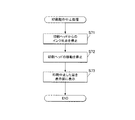
本実施形態において、プッシュスイッチ24から指非検出信号が出力された場合には、印刷制御部53は、第1の実施形態で説明したのと同様の処理により、印刷動作中止処理(図12及び図13等参照)を行う。その後、印刷指U1が再度印刷指載置面21a上に載置され、印刷指U1によってプッシュスイッチ24が押されて指検出信号が出力されると、図17に示すように、印刷制御部53は、印刷動作の再開処理を行う。
具体的には、印刷ヘッド46のモニタリング結果等に基づいて印刷指載置面21a上に載置されている印刷指U1の現在の爪部Tの印刷状況を取得し(ステップS81)、爪部Tへの印刷動作が開始されているか否かを判断する(ステップS82)。
爪部Tへの印刷動作が開始されていないと判断される場合(ステップS82;NO)には、印刷制御部53は、印刷ヘッド46のヘッド駆動部461に出力する印刷用画像データを初期化するとともに(ステップS83)、ヘッド移動回路56を制御して、印刷ヘッド46が印刷初期位置に位置するように、印刷ヘッド46を移動させる(ステップS84)。そして、改めて印刷初期位置から爪部Tへの印刷を開始させる(ステップS85)。
In the present embodiment, when a finger non-detection signal is output from the
Specifically, the current printing status of the nail portion T of the printing finger U1 placed on the printing
When it is determined that the printing operation on the nail portion T has not been started (step S82; NO), the
他方、爪部Tへの印刷動作が開始されていると判断される場合(ステップS82;YES)には、印刷制御部53は、爪部Tへの印刷が完了しているか否かを判断し(ステップS86)、印刷が完了している場合(ステップS86;YES)には、処理を終了する。この場合、印刷が終了している旨を表示部13に表示させてもよい。
一方、印刷が完了していない場合(ステップS86;NO)には、印刷制御部53は、既印刷画像取得手段である撮影部30により撮影された印刷指載置面21a上に載置されている印刷指U1の現在の爪部Tの画像である既印刷画像を取得する(ステップS87)。そして、印刷制御部53は、この既印刷画像に基づいて、印刷を再開すべき画像の位置情報を取得するとともに(ステップS88)、印刷を再開する際の印刷ヘッド46の位置情報を取得する(ステップS89)。
On the other hand, when it is determined that the printing operation on the nail portion T has been started (step S82; YES), the
On the other hand, when the printing is not completed (step S86; NO), the
具体的には、例えば、1つの爪部Tについて、2回の走査で印刷を行う場合、図18に示すように、1回目の走査が終わった時点でプッシュスイッチ24から指非検出信号が出力されて印刷動作が停止した場合には、当該爪部Tについての2走査目の画像が、印刷を再開すべき画像の位置情報として印刷制御部53に取得される。また、当該爪部Tについての2走査目の印刷開始位置が印刷を再開する際の印刷ヘッド46の位置情報として印刷制御部53に取得される。
また、例えば、1つの爪部Tについて、2回の走査で印刷を行う場合、図19に示すように、1回目の走査の途中でプッシュスイッチ24から指非検出信号が出力されて印刷動作が停止した場合には、当該爪部Tについての1走査目における続きの画像が、印刷を再開すべき画像の位置情報として印刷制御部53に取得される。また、当該爪部Tについての1走査目における印刷動作の停止位置に隣接する位置が印刷を再開する際の印刷ヘッド46の位置情報として印刷制御部53に取得される。
なお、印刷ヘッド46のノズル面462が、爪部Tに対向する印刷ヘッド46の面よりも小さい場合には、印刷を再開した際に既存画像との間に隙間が空かないように、印刷動作の停止位置に隣接する位置は、図19に示すように、ノズル面462の寸法によって定められる。
Specifically, for example, when printing is performed with two scans for one nail portion T, a finger non-detection signal is output from the
In addition, for example, when printing is performed with two scans for one nail portion T, as shown in FIG. 19, a finger non-detection signal is output from the
When the nozzle surface 462 of the
印刷を再開すべき画像の位置情報及び印刷を再開する際の印刷ヘッド46の位置情報を取得すると、印刷制御部53は、印刷ヘッド46のヘッド駆動部461に印刷を再開すべき画像のデータを出力するとともに(ステップS90)、ヘッド移動回路56を制御して、印刷ヘッド46が印刷を再開する際の印刷ヘッド46の位置に位置するように、印刷ヘッド46を移動させる(ステップS91)。そして、この印刷を再開すべき画像のデータに基づいて、印刷を再開すべき位置から爪部Tへの印刷を開始する(ステップS92)。
When the position information of the image to be restarted and the position information of the
以上のように、本実施形態によれば、プッシュスイッチ24から指検出信号が出力された後に、プッシュスイッチ24から指非検出信号が出力されて、一旦印刷が中止された場合でも、再度プッシュスイッチ24から指検出信号が出力された際には、印刷中止時点の印刷状況に応じて、適切に印刷を再開することができる。
これにより、改めて印刷の設定をやり直す等の手間を省いて、爪部Tへの印刷を行うことができる。また、印刷指U1を印刷指挿入部20aに挿入してプッシュスイッチ24を操作することにより印刷を再開できるため、一旦手を印刷指挿入部20aから引き抜いて印刷動作開始のための操作ボタンを操作する等の手間が不要であり、簡易かつ迅速に爪部Tへの印刷を行うことができる。
As described above, according to the present embodiment, after the finger detection signal is output from the
Accordingly, it is possible to perform printing on the nail portion T without the trouble of redoing the print setting again. Further, since printing can be resumed by inserting the printing finger U1 into the printing
[第3の実施の形態]
次に、本発明に係るネイルプリント装置の第3の実施形態について説明する。なお、本実施形態は、指載置検出手段であるプッシュスイッチから指非検出信号が出力された際の処理が第1の実施形態と異なるものであるため、以下においては、特に第1の実施形態と異なる点について説明する。
[Third Embodiment]
Next, a third embodiment of the nail print apparatus according to the present invention will be described. In the present embodiment, the processing when a finger non-detection signal is output from a push switch that is a finger placement detection unit is different from that in the first embodiment. A different point from a form is demonstrated.
本実施形態においてネイルプリント装置は、第1の実施形態同様、指載置検出手段であるプッシュスイッチ24を備えており、印刷指挿入部20aに挿入された印刷指U1が印刷指載置面21a上に載置されると、印刷指U1によってプッシュスイッチ24が押されて指検出信号が出力されるようになっている。また、印刷指U1が印刷指載置面21aから浮き上がる等によりプッシュスイッチ24から離れると、プッシュスイッチ24から指非検出信号が出力される。
本実施形態では、プッシュスイッチ24から出力された指検出信号及び指非検出信号は、制御部50(印刷制御部53)を介さず、直接に、印刷ヘッド46のヘッド駆動部461の動作を制御するヘッド駆動回路55、印刷ヘッド46を移動させる第1のモータ43、第2のモータ47の動作を制御するヘッド移動回路56に出力されるようになっており、プッシュスイッチ24から指非検出信号が出力されると、ヘッド駆動部461による印刷ヘッド46の駆動及び/又は第1のモータ43、第2のモータ47による印刷ヘッド46の移動が停止されるようになっている。
In the present embodiment, the nail printing apparatus includes a
In the present embodiment, the finger detection signal and finger non-detection signal output from the
なお、本実施形態においては、プッシュスイッチ24から指検出信号が出力されて印刷動作が開始されると、印刷制御部53には、印刷動作中フラグが立ち、印刷動作用のヘッド駆動信号、印刷動作用のヘッド移動信号をヘッド駆動回路55及びヘッド移動回路56に出力するようになっている。また、プッシュスイッチ24から指非検出信号が出力される等により印刷動作中フラグが立っていない非印刷時となった場合には、印刷制御部53は、この印刷動作用のヘッド駆動信号、印刷動作用のヘッド移動信号とは異なる印刷動作以外の動作を指示する非印刷時のヘッド駆動信号、非印刷時のヘッド移動信号をヘッド駆動回路55及びヘッド移動回路56に出力するようになっている。
本実施形態では、プッシュスイッチ24から指非検出信号が出力されることにより、ヘッド駆動部461による印刷ヘッド46の駆動及び/又は第1のモータ43、第2のモータ47による印刷ヘッド46の移動が停止された場合でも、印刷動作中フラグが立っていない非印刷状態下で出力される印刷動作以外の動作を指示する非印刷時のヘッド駆動信号、非印刷時のヘッド移動信号は、プッシュスイッチ24からの指非検出信号に拘らず、ヘッド駆動回路55及びヘッド移動回路56に有効に出力可能となっている。
したがって、印刷制御部53は、プッシュスイッチ24から指検出信号が出力されていない非印刷時においても、非印刷時のヘッド駆動信号、非印刷時のヘッド移動信号をヘッド駆動回路55及びヘッド移動回路56に出力することにより、メンテナンスのための印刷ヘッドの移動や空吐出等のメンテナンス動作を行わせることが可能となっている。
In the present embodiment, when a finger detection signal is output from the
In the present embodiment, when the finger non-detection signal is output from the
Therefore, the
なお、その他の構成は、第1の実施形態と同様であるため、その説明を省略する。 Since other configurations are the same as those of the first embodiment, the description thereof is omitted.
次に、本実施形態におけるネイルプリント装置による印刷制御方法について説明する。 Next, a printing control method by the nail printing apparatus in the present embodiment will be described.
本実施形態において、プッシュスイッチ24から指非検出信号が出力された場合には、この指非検出信号がヘッド駆動回路55及びヘッド移動回路56に直接出力されて、ヘッド駆動部461による印刷ヘッド46の駆動及び/又は第1のモータ43、第2のモータ47による印刷ヘッド46の移動が直ちに停止される。
印刷制御部53は、プッシュスイッチ24から指非検出信号が出力され、非印刷時となると、印刷動作以外の動作を指示する非印刷時のヘッド駆動信号、非印刷時のヘッド移動信号をヘッド駆動回路55及びヘッド移動回路56に出力することが可能となる。非印刷時のヘッド駆動信号、非印刷時のヘッド移動信号がヘッド駆動回路55及びヘッド移動回路56に出力されると、プッシュスイッチ24からの指非検出信号の出力に拘らず、ヘッド駆動回路55及びヘッド移動回路56を制御することが可能となり、印刷制御部53は、必要に応じて、メンテナンスのための印刷ヘッド46の移動やインクの空吐出等のメンテナンス動作を行わせる。
In this embodiment, when a finger non-detection signal is output from the
The
以上のように、本実施形態によれば、プッシュスイッチ24から指非検出信号が出力された場合に、印刷制御部53を介さず、直接ヘッド駆動回路55及びヘッド移動回路56に信号が出力されるため、印刷ヘッド46の移動やインク吐出を直ちに停止させることができる。
このため、印刷指U1の浮き上がり等による印刷ヘッドと爪部Tとの干渉や、不適切な状態のまま爪部Tにインクが吐出されることをより確実に防止することができる。
また、この場合でも、印刷制御部53は、印刷動作以外の動作を指示する非印刷時のヘッド駆動信号、非印刷時のヘッド移動信号をヘッド駆動回路55及びヘッド移動回路56に出力することが可能に構成されているため、プッシュスイッチ24から指非検出信号が出力された場合でも、保湿キャップ上に印刷ヘッド46を移動させたり、インクの空吐出を行わせる等のメンテナンス動作を行わせることが可能となっている。
As described above, according to the present embodiment, when a finger non-detection signal is output from the
For this reason, it is possible to more surely prevent interference between the print head and the nail portion T due to the lifting of the printing finger U1 or the like, and discharge of ink to the nail portion T in an inappropriate state.
Even in this case, the
なお、本発明は、上記各実施形態に限定されず、適宜変更可能であることはいうまでもない。
例えば、本実施形態では、指載置検出手段としてのプッシュスイッチ24が4本の印刷指U1に対応して4つ設けられている例について説明したが、プッシュスイッチ24の数はこれに限定されない。
例えば、図20及び図21に示すように、各印刷指U1に対応して、それぞれ印刷指U1の延在方向に複数のプッシュスイッチ26を配置してもよい。この場合、印刷指載置面21aに載置されている印刷指U1に対応する全てのプッシュスイッチ26から指検出信号が出力されたときに、印刷が開始され、いずれか1つのプッシュスイッチ26から指非検出信号が出力されたときには、印刷を中止するように構成する。
このような構成とした場合には、より様々な、印刷指U1の動きを正確に検出することが可能となり、印刷ヘッド46と印刷指U1とが接触・干渉する懸念をより少なくすることができる。
Needless to say, the present invention is not limited to the above-described embodiments and can be appropriately changed.
For example, in the present embodiment, an example in which four
For example, as shown in FIGS. 20 and 21, a plurality of push switches 26 may be arranged in the extending direction of the printing finger U <b> 1 corresponding to each printing finger U <b> 1. In this case, when the finger detection signal is output from all the push switches 26 corresponding to the printing finger U1 placed on the printing
With such a configuration, it is possible to accurately detect various movements of the print finger U1, and to reduce the concern that the
また、指載置検出手段は、例えばシーソースイッチのように接点がON/OFFで固定されるものでなく、印刷指U1の印刷指載置面21aへの接離を検出できるものであれば何でも適用することができ、プッシュスイッチ24に限定されない。
例えば、図22及び図23に示すように、各印刷指U1に対応する位置に、印刷指載置面21aに印刷指U1が載置されると印刷指U1が接触することによって指検出信号を出力し、印刷指U1が離れることにより指非検出信号を出力する接触センサ27等の面センサを設けてもよい。接触センサ27の大きさや範囲は特に限定されないが、印刷指U1の印刷指載置面21aへの接離を適切に検出できるようにするため、印刷指U1の先端部から第一関節辺りに対応する範囲に位置するように配置されることが好ましい。
このように構成した場合には、印刷指U1の印刷指載置面21aへの接離を面で検出できるため、印刷ヘッド46と印刷指U1とが接触・干渉することをより確実に防止することができる。
また、指載置検出手段として印刷指載置面21a上に微小なタッチパネルを設置し、表示画面を見ながら印刷指U1を載置する位置を確認できるようにする構成でもよい。この場合には、印刷指U1を載置する際の目安として微小なタッチパネルに米粒程度の物体を設置すると印刷指U1を載置する場所がより容易に分かるため好ましい。
その他、広めのタッチパネルを印刷指載置面21a上に設けて、印刷指U1がどこに載置されたか(タッチパネルとしてはどこを押圧されたか)を認識することによって印刷指U1の印刷指載置面21aへの接離を検出するようにしてもよい。この場合、押圧された場所が移動したり、押圧されなくなった場合に印刷指U1が動いたものと判断され、指非検出信号が出力される。
Also, the finger placement detection means is not anything that can detect contact / separation of the printing finger U1 with respect to the printing
For example, as shown in FIG. 22 and FIG. 23, when the print finger U1 is placed on the print
In such a configuration, the contact / separation of the printing finger U1 with respect to the printing
Further, a configuration may be adopted in which a minute touch panel is installed on the print
In addition, a wide touch panel is provided on the print
また、本実施形態では、複数の印刷指U1を同時に印刷する場合にも、1本の印刷指U1のみに印刷する場合にもともに対応可能であるネイルプリント装置を例として説明したが、ネイルプリント装置はこれに限定されず、例えば、印刷指U1を1本ずつ挿入して印刷する装置であってもよい。 In the present embodiment, the nail printing apparatus is described as an example that can cope with both the case where a plurality of printing fingers U1 are printed simultaneously and the case where printing is performed only on one printing finger U1. The apparatus is not limited to this, and may be an apparatus that inserts printing fingers U1 one by one and performs printing.
また、本実施形態では、制御部50のROM、RAMの他に印刷指記憶部54を備える構成としたが、制御部50のRAM等が印刷指記憶手段として機能する構成としてもよい。
In this embodiment, the print
以上本発明のいくつかの実施形態を説明したが、本発明の範囲は、上述の実施の形態に限定するものではなく、特許請求の範囲に記載された発明の範囲とその均等の範囲を含む。
以下に、この出願の願書に最初に添付した特許請求の範囲に記載した発明を付記する。付記に記載した請求項の項番は、この出願の願書に最初に添付した特許請求の範囲の通りである。
〔付記〕
<請求項1>
印刷しようとする爪部に対応する指である印刷指を載置する印刷指載置手段と、この印刷指載置手段に載置されている印刷指の爪部に印刷を施す印刷ヘッドを有する印刷手段とを備えているネイルプリント装置において、
前記印刷指載置手段に設けられ、前記印刷指載置手段に前記印刷指が載置された際に、指検出信号を出力し、その後、この載置された前記印刷指が離れた際に、指非検出信号を出力する指載置検出手段と、
この指載置検出手段から指検出信号が出力されると、この信号出力時又はこの信号出力時から所定の時間経過後に前記爪部に対して印刷を施す印刷動作を開始し、その後、印刷動作中に、この指載置検出手段から指非検出信号が出力されると、前記爪部への印刷動作を停止するように、前記印刷手段を制御する印刷制御手段と、
を備えていることを特徴とするネイルプリント装置。
<請求項2>
前記指載置検出手段は、前記印刷指載置手段に載置された一の印刷指に対して複数設けられており、
前記印刷制御手段は、前記印刷指載置手段に設けられている全ての前記指載置検出手段から指検出信号が出力されると、信号出力時又はこの信号出力時から所定の時間経過後に前記爪部への印刷動作を開始し、印刷動作中に、これらの指載置検出手段のうちの少なくとも1つから指非検出信号が出力されると、前記爪部への印刷動作を停止するように、前記印刷手段を制御することを特徴とする請求項1に記載のネイルプリント装置。
<請求項3>
前記指載置検出手段は、前記印刷指載置手段に前記印刷指が載置されると前記印刷指によって押圧されることによって指検出信号を出力し、前記印刷指が当該指載置検出手段から離れることにより指非検出信号を出力するプッシュスイッチであることを特徴とする請求項1又は請求項2に記載のネイルプリント装置。
<請求項4>
前記指載置検出手段は、前記印刷指載置手段に前記印刷指が載置されると前記印刷指が接触することによって指検出信号を出力し、前記印刷指が当該指載置検出手段から離れることにより指非検出信号を出力する接触センサであることを特徴とする請求項1又は請求項2に記載のネイルプリント装置。
<請求項5>
前記印刷指載置手段に載置されている前記印刷指の位置を検出する印刷指検出手段をさらに備え、
前記指載置検出手段から指非検出信号が出力されると、前記印刷制御手段は、前記印刷指検出手段によって検出された前記印刷指の位置に応じて、前記印刷指の挿入方向の奥側であって前記印刷指から離れる方向に前記印刷ヘッドを移動させることを特徴とする請求項1から請求項4のいずれか一項に記載のネイルプリント装置。
<請求項6>
前記印刷指載置手段に複数の印刷指を同時に載置して、複数の爪部に対して印刷が可能となっており、
前記印刷指載置手段に載置されている前記印刷指の数と、現に印刷中の印刷指の種類及び/又は位置を記憶する印刷指記憶手段をさらに備え、
前記指載置検出手段から指非検出信号が出力されると、前記印刷制御手段は、前記印刷指記憶手段に記憶されている前記印刷指載置手段に載置されている前記印刷指の数と、現に印刷中の印刷指の種類及び/又は位置に応じて、前記印刷指の挿入方向の奥側であって前記印刷指から離れる方向に前記印刷ヘッドを移動させることを特徴とする請求項1から請求項5のいずれか一項に記載のネイルプリント装置。
<請求項7>
前記指載置検出手段から指検出信号が出力された後、前記爪部に対する印刷動作開始前に、前記指載置検出手段から指非検出信号が出力された場合には、前記指載置検出手段から再度指検出信号が出力された場合に、前記印刷制御手段は、印刷初期位置から爪部の印刷を開始させるように構成され、
前記爪部に印刷された既印刷画像を読み取る既印刷画像取得手段をさらに備え、
前記爪部に対する印刷動作開始後に前記指載置検出手段から指非検出信号が出力された場合には、前記指載置検出手段から再度指検出信号が出力された場合に、前記印刷制御手段は、前記既印刷画像取得手段によって読み取られた既印刷画像に基づいて再印刷位置を判断し、前記爪部への印刷動作停止時の印刷データに基づいて当該再印刷位置から再印刷を開始させることを特徴とする請求項1から請求項6のいずれか一項に記載のネイルプリント装置。
<請求項8>
前記指載置検出手段からの指検出信号/指非検出信号は、前記印刷ヘッドを駆動させるヘッド駆動回路及び/又は前記印刷ヘッドを駆動させるヘッド移動回路に出力され、
前記指載置検出手段から指非検出信号が出力されると、前記印刷ヘッドの駆動及び/又は前記印刷ヘッドの移動が停止されることを特徴とする請求項1から請求項4のいずれか一項に記載のネイルプリント装置。
<請求項9>
前記印刷制御手段は、非印刷時において、前記指載置検出手段からの指非検出信号に拘らず、印刷動作以外の前記ヘッド駆動回路による前記印刷ヘッドの駆動及び/又は前記ヘッド移動回路による前記印刷ヘッドの駆動を有効とする非印刷時動作信号を前記ヘッド駆動回路及び/又は前記ヘッド移動回路に出力することを特徴とする請求項8に記載のネイルプリント装置。
<請求項10>
印刷しようとする爪部に対応する指である印刷指を載置する印刷指載置手段と、この印刷指載置手段に載置されている印刷指の爪部に印刷を施す印刷ヘッドを有する印刷手段とを備えているネイルプリント装置に用いられる印刷制御方法において、
前記印刷指載置手段に前記印刷指が載置された際に、指検出信号を出力し、その後、この載置された前記印刷指が離れた際に、指非検出信号を出力するように制御する指載置検出ステップと、
この指載置検出ステップにて指検出信号が出力されると、この信号出力時又はこの信号出力時から所定の時間経過後に前記爪部に対して印刷を施す印刷動作を開始し、その後、印刷動作中に、この指載置検出ステップにて指非検出信号が出力されると、前記爪部への印刷動作を停止するように、前記印刷手段を制御する印刷制御ステップと、
を備えていることを特徴とする印刷制御方法。
Although several embodiments of the present invention have been described above, the scope of the present invention is not limited to the above-described embodiments, but includes the scope of the invention described in the claims and equivalents thereof. .
The invention described in the scope of claims attached to the application of this application will be added below. The item numbers of the claims described in the appendix are as set forth in the claims attached to the application of this application.
[Appendix]
<Claim 1>
A printing finger placement unit that places a printing finger that is a finger corresponding to the nail portion to be printed, and a print head that performs printing on the nail portion of the printing finger placed on the printing finger placement unit In a nail printing apparatus comprising a printing means,
When the printing finger is placed on the printing finger placement unit, the finger detection signal is output when the printing finger is placed on the printing finger placement unit, and then when the placed printing finger is released. Finger placement detection means for outputting a finger non-detection signal;
When a finger detection signal is output from this finger placement detection means, a printing operation is started to print on the nail portion at the time of this signal output or after a predetermined time has elapsed from the time of this signal output. During this, when a finger non-detection signal is output from this finger placement detection means, a print control means for controlling the printing means to stop the printing operation on the nail part,
A nail printing apparatus comprising:
<Claim 2>
A plurality of the finger placement detection means are provided for one printing finger placed on the printing finger placement means,
When the finger detection signal is output from all the finger placement detection means provided in the print finger placement means, the print control means outputs the signal or after a predetermined time has elapsed since the signal output. A printing operation on the nail portion is started, and when a finger non-detection signal is output from at least one of these finger placement detection means during the printing operation, the printing operation on the nail portion is stopped. The nail printing apparatus according to
<Claim 3>
The finger placement detection means outputs a finger detection signal when pressed by the printing finger when the printing finger is placed on the printing finger placement means, and the printing finger is detected by the finger placement detection means. The nail print apparatus according to
<Claim 4>
The finger placement detection means outputs a finger detection signal when the printing finger comes into contact with the printing finger placement means when the printing finger is placed on the printing finger placement means, and the printing finger is output from the finger placement detection means. The nail print apparatus according to
<Claim 5>
A print finger detecting means for detecting a position of the print finger placed on the print finger placing means;
When a finger non-detection signal is output from the finger placement detection unit, the print control unit is configured to move the print finger in the insertion direction in accordance with the position of the print finger detected by the print finger detection unit. 5. The nail printing apparatus according to
<Claim 6>
A plurality of printing fingers are simultaneously placed on the printing finger placement means, and printing on a plurality of nail portions is possible.
Printing finger storage means for storing the number of printing fingers placed on the printing finger placement means and the type and / or position of the printing finger currently being printed;
When a finger non-detection signal is output from the finger placement detection means, the print control means counts the number of print fingers placed on the print finger placement means stored in the print finger storage means. The print head is moved in a direction away from the print finger in the back side in the insertion direction of the print finger according to the type and / or position of the print finger currently being printed. The nail printing apparatus according to any one of
<Claim 7>
If a finger non-detection signal is output from the finger placement detection means after the finger detection signal is output from the finger placement detection means and before the printing operation for the nail portion is started, the finger placement detection is performed. When the finger detection signal is output again from the means, the print control means is configured to start printing of the nail portion from the print initial position,
A pre-printed image acquisition means for reading a pre-printed image printed on the nail portion;
When a finger non-detection signal is output from the finger placement detection means after the start of a printing operation on the nail part, when the finger detection signal is output again from the finger placement detection means, the print control means Determining the reprint position based on the preprinted image read by the preprinted image acquisition means, and starting reprinting from the reprint position based on the print data when the printing operation to the nail portion is stopped. The nail print apparatus according to any one of
<Claim 8>
The finger detection signal / finger non-detection signal from the finger placement detection means is output to a head drive circuit that drives the print head and / or a head movement circuit that drives the print head,
5. The drive of the print head and / or the movement of the print head are stopped when a finger non-detection signal is output from the finger placement detection means. The nail printing apparatus according to item.
<Claim 9>
The printing control means is configured to drive the printing head by the head driving circuit and / or the head moving circuit other than the printing operation regardless of the finger non-detection signal from the finger placement detection means during non-printing. 9. The nail printing apparatus according to claim 8, wherein a non-printing operation signal for enabling driving of the print head is output to the head driving circuit and / or the head moving circuit.
<Claim 10>
A printing finger placement unit that places a printing finger that is a finger corresponding to the nail portion to be printed, and a print head that performs printing on the nail portion of the printing finger placed on the printing finger placement unit In a printing control method used for a nail printing apparatus provided with a printing means,
A finger detection signal is output when the printing finger is placed on the printing finger placement means, and then a finger non-detection signal is output when the placed printing finger is released. A finger placement detection step to be controlled;
When a finger detection signal is output in this finger placement detection step, a printing operation for printing on the nail part is started after this signal is output or after a predetermined time has elapsed from the time of this signal output. During operation, when a finger non-detection signal is output in this finger placement detection step, a printing control step for controlling the printing unit so as to stop the printing operation on the nail part;
A printing control method comprising:
1 ネイルプリント装置
2 ケース本体
4 蓋体
12 操作部
13 表示部
20a 印刷指挿入部
20b 非印刷指挿入部
20c 掴み部(隔壁)
20 印刷指固定部
21a 印刷指載置面
23 印刷可能領域
24 プッシュスイッチ
30 撮影部
32 カメラ
33 照明灯(LED)
40 印刷部
46 印刷ヘッド
50 制御部
53 印刷制御部
54 印刷指記憶部
X 指挿入方向
T 爪部
U1 印刷指
DESCRIPTION OF
20 Printing
40
Claims (9)
この印刷指載置手段に載置されている印刷指の爪部に印刷を施す印刷ヘッドを有する印刷手段と、
前記印刷指載置手段に設けられ、前記印刷指載置手段に前記印刷指が載置された際に、指検出信号を出力し、前記印刷指が前記印刷指載置手段から離れた際に、指非検出信号を出力する指載置検出手段と、
前記印刷指載置手段に載置されている前記印刷指の位置を検出する印刷指検出手段と、
前記指載置検出手段から前記指検出信号が出力されたとき、前記指検出信号の信号出力時又はこの信号出力時から所定の時間経過後に前記印刷手段により前記爪部に対して印刷を施す印刷動作を開始させ、前記印刷動作中に、前記指載置検出手段から前記指非検出信号が出力されたとき、前記印刷動作を停止させとともに、前記印刷指検出手段によって検出された前記印刷指の位置に応じて、前記印刷指から離れる方向に前記印刷ヘッドを移動させるように、前記印刷手段を制御する印刷制御手段と、
を備えていることを特徴とするネイルプリント装置。 A print finger placement means for placing a print finger that is a finger corresponding to the nail portion to be printed;
A printing means having a print head for printing on the nail portion of the printing finger placed on the printing finger placement means;
When the printing finger is placed on the printing finger placement unit, the finger detection signal is output when the printing finger is placed on the printing finger placement unit, and when the printing finger is separated from the printing finger placement unit. Finger placement detection means for outputting a finger non-detection signal;
Printing finger detection means for detecting the position of the printing finger placed on the printing finger placement means;
When the finger detection signal is output from the finger placement detection means, printing is performed on the nail portion by the printing means when the signal of the finger detection signal is output or after a predetermined time has elapsed from the output of this signal. When the finger placement detection means outputs the finger non-detection signal during the printing operation, the printing operation is stopped and the printing finger detected by the printing finger detection means is started. depending on the position, in so that moving the print head in a direction away from the printing finger, and print control means for controlling said printing means,
A nail printing apparatus comprising:
前記印刷制御手段は、前記印刷指載置手段に設けられている全ての前記指載置検出手段から前記指検出信号が出力されると、前記信号出力時又はこの信号出力時から所定の時間経過後に前記印刷動作を開始させ、印刷動作中に、これらの指載置検出手段のうちの少なくとも1つから前記指非検出信号が出力されると、前記印刷動作を停止させるように、前記印刷手段を制御することを特徴とする請求項1に記載のネイルプリント装置。 A plurality of the finger placement detection means are provided for one printing finger placed on the printing finger placement means,
When the finger detection signals are output from all the finger placement detection means provided in the print finger placement means, the print control means outputs a predetermined time from the time of the signal output or the time of the signal output. The printing unit is configured to start the printing operation later, and stop the printing operation when the finger non-detection signal is output from at least one of these finger placement detection units during the printing operation. The nail printing apparatus according to claim 1, wherein the nail printing apparatus is controlled.
前記印刷指載置手段に載置されている前記印刷指の数と、現に印刷中の印刷指の種類及び/又は位置を記憶する印刷指記憶手段をさらに備え、
前記指載置検出手段から前記指非検出信号が出力されると、前記印刷制御手段は、前記印刷指記憶手段に記憶されている前記印刷指載置手段に載置されている前記印刷指の数と、現に印刷中の印刷指の種類及び/又は位置に応じて、前記印刷指の挿入方向の奥側であって前記印刷指から離れる方向に前記印刷ヘッドを移動させることを特徴とする請求項1から請求項4のいずれか一項に記載のネイルプリント装置。 A plurality of the printing fingers are simultaneously placed on the printing finger placing means, and printing on a plurality of nail portions is possible.
Printing finger storage means for storing the number of printing fingers placed on the printing finger placement means and the type and / or position of the printing finger currently being printed;
When the finger non-detection signal is output from the finger placement detection means, the print control means is configured to output the print finger placed on the print finger placement means stored in the print finger storage means. The print head is moved in a direction away from the print finger in the back side in the insertion direction of the print finger according to the number and the type and / or position of the print finger currently being printed. The nail printing apparatus according to any one of claims 1 to 4 .
前記爪部に印刷された既印刷画像を読み取る既印刷画像取得手段をさらに備え、
前記爪部に対する印刷動作開始後に前記指載置検出手段から前記指非検出信号が出力された後、前記指載置検出手段から再度、前記指検出信号が出力された場合に、前記印刷制御手段は、前記既印刷画像取得手段によって読み取られた既印刷画像に基づいて再印刷位置を判断し、前記爪部への前記印刷動作の停止時の印刷データに基づいて当該再印刷位置から再印刷を開始させることを特徴とする請求項1から請求項5のいずれか一項に記載のネイルプリント装置。 After the finger detection signal is output from the finger placement detection means, and before the printing operation for the nail portion is started, after the finger non-detection signal is output from the finger placement detection means, When the finger detection signal is output again from the position detection means, the print control means is configured to start printing of the nail portion from the initial printing position,
A pre-printed image acquisition means for reading a pre-printed image printed on the nail portion;
The print control means when the finger placement detection means outputs the finger detection signal again after the finger placement detection means is outputted after the finger placement detection means is outputted after the printing operation for the nail portion is started. Determines a reprint position based on the preprinted image read by the preprinted image acquisition means, and reprints from the reprint position based on the print data when the printing operation to the nail portion is stopped. The nail print apparatus according to any one of claims 1 to 5 , wherein the nail print apparatus is started.
前記指載置検出手段から前記指非検出信号が出力されると、前記印刷ヘッドの駆動及び/又は前記印刷ヘッドの移動が停止されることを特徴とする請求項1から請求項4のいずれか一項に記載のネイルプリント装置。 The finger detection signal / the finger non-detection signal from the finger placement detection means is output to a head drive circuit that drives the print head and / or a head movement circuit that drives the print head,
The drive of the print head and / or the movement of the print head are stopped when the finger non-detection signal is output from the finger placement detection means. The nail printing apparatus according to one item.
前記印刷指載置手段に前記印刷指が載置された際に、指検出信号を出力し、前記印刷指が前記印刷指載置手段から離れた際に、指非検出信号を出力するように制御する指載置検出ステップと、
前記印刷指載置手段に載置されている前記印刷指の位置を検出する印刷指検出ステップと、
前記指載置検出ステップにて前記指検出信号が出力されると、前記指検出信号の信号出力時又はこの信号出力時から所定の時間経過後に前記印刷手段により前記爪部に対して印刷を施す印刷動作を開始させ、前記印刷動作中に、前記指載置検出ステップにて前記指非検出信号が出力されると、前記印刷動作を停止させるとともに、前記印刷指検出ステップによって検出された前記印刷指の位置に応じて、前記印刷指から離れる方向に前記印刷ヘッドを移動させるように、前記印刷手段を制御する印刷制御ステップと、
を備えていることを特徴とする印刷制御方法。 A printing finger placement unit that places a printing finger that is a finger corresponding to the nail portion to be printed, and a print head that performs printing on the nail portion of the printing finger placed on the printing finger placement unit In a printing control method used for a nail printing apparatus provided with a printing means,
A finger detection signal is output when the printing finger is placed on the printing finger placement means, and a finger non-detection signal is output when the printing finger leaves the printing finger placement means. A finger placement detection step to be controlled;
A print finger detecting step of detecting a position of the print finger placed on the print finger placing means;
When the finger detection signal is output in the finger placement detection step, printing is performed on the nail portion by the printing unit when the signal of the finger detection signal is output or after a predetermined time has elapsed since the signal output. When the finger non-detection signal is output in the finger placement detection step during the printing operation, the printing operation is stopped and the printing detected by the printing finger detection step is started. A printing control step for controlling the printing means to move the print head in a direction away from the printing finger in accordance with the position of the finger ;
A printing control method comprising:
Priority Applications (1)
| Application Number | Priority Date | Filing Date | Title |
|---|---|---|---|
| JP2011117564A JP5724634B2 (en) | 2011-05-26 | 2011-05-26 | Nail printing apparatus and printing control method |
Applications Claiming Priority (1)
| Application Number | Priority Date | Filing Date | Title |
|---|---|---|---|
| JP2011117564A JP5724634B2 (en) | 2011-05-26 | 2011-05-26 | Nail printing apparatus and printing control method |
Publications (3)
| Publication Number | Publication Date |
|---|---|
| JP2012245079A JP2012245079A (en) | 2012-12-13 |
| JP2012245079A5 JP2012245079A5 (en) | 2014-05-08 |
| JP5724634B2 true JP5724634B2 (en) | 2015-05-27 |
Family
ID=47466127
Family Applications (1)
| Application Number | Title | Priority Date | Filing Date |
|---|---|---|---|
| JP2011117564A Active JP5724634B2 (en) | 2011-05-26 | 2011-05-26 | Nail printing apparatus and printing control method |
Country Status (1)
| Country | Link |
|---|---|
| JP (1) | JP5724634B2 (en) |
Cited By (1)
| Publication number | Priority date | Publication date | Assignee | Title |
|---|---|---|---|---|
| CN105708107A (en) * | 2016-03-23 | 2016-06-29 | 上海斐讯数据通信技术有限公司 | Nail filing auxiliary device and nail filing method |
Families Citing this family (7)
| Publication number | Priority date | Publication date | Assignee | Title |
|---|---|---|---|---|
| JP6377353B2 (en) * | 2013-12-20 | 2018-08-22 | ローランドディー.ジー.株式会社 | Printing apparatus and printing method |
| JP6561462B2 (en) * | 2014-12-19 | 2019-08-21 | カシオ計算機株式会社 | Nail printing apparatus and drawing method of nail printing apparatus |
| EP3121019B1 (en) | 2015-07-09 | 2020-01-01 | Funai Electric Co., Ltd. | Ejection device |
| JP2017018588A (en) * | 2015-07-09 | 2017-01-26 | 船井電機株式会社 | Injection device |
| JP7067062B2 (en) * | 2018-01-09 | 2022-05-16 | カシオ計算機株式会社 | Drawing device, drawing method and program |
| JP7067166B2 (en) * | 2018-03-20 | 2022-05-16 | カシオ計算機株式会社 | Nail printing device, finger type determination method and program |
| JP2020054716A (en) * | 2018-10-04 | 2020-04-09 | カシオ計算機株式会社 | Printing system, terminal device, printing method, and program |
Family Cites Families (4)
| Publication number | Priority date | Publication date | Assignee | Title |
|---|---|---|---|---|
| AU1353299A (en) * | 1997-12-24 | 1999-07-19 | Jit Ceremony Co., Ltd. | Nail art method and device |
| JP2000006384A (en) * | 1998-06-25 | 2000-01-11 | Mitsumi Electric Co Ltd | Printing device capable of printing on three-dimensional surface |
| US6286517B1 (en) * | 1998-12-22 | 2001-09-11 | Pearl Technology Holdings, Llc | Fingernail and toenail decoration using ink jets |
| JP3016147B1 (en) * | 1998-12-25 | 2000-03-06 | 株式会社アトラス | Nail art equipment |
-
2011
- 2011-05-26 JP JP2011117564A patent/JP5724634B2/en active Active
Cited By (1)
| Publication number | Priority date | Publication date | Assignee | Title |
|---|---|---|---|---|
| CN105708107A (en) * | 2016-03-23 | 2016-06-29 | 上海斐讯数据通信技术有限公司 | Nail filing auxiliary device and nail filing method |
Also Published As
| Publication number | Publication date |
|---|---|
| JP2012245079A (en) | 2012-12-13 |
Similar Documents
| Publication | Publication Date | Title |
|---|---|---|
| JP5724634B2 (en) | Nail printing apparatus and printing control method | |
| EP3339043B1 (en) | Printing device; printing method and recording medium | |
| JP5915571B2 (en) | Nail printing apparatus and printing method for nail printing apparatus | |
| JP6953815B2 (en) | Program, information processing device, display method, droplet ejection device, droplet ejection system | |
| JP5141742B2 (en) | Nail printing apparatus and printing control method | |
| JP6561462B2 (en) | Nail printing apparatus and drawing method of nail printing apparatus | |
| JP5728885B2 (en) | Nail printing apparatus and printing control method | |
| JP2011255013A (en) | Nail printer and print controlling method | |
| US20130106970A1 (en) | Nail print apparatus including display control unit which distinguishes between printed region and non-printed region in fingernail under printing to display fingernail | |
| JP2014121344A (en) | Nail printing device and printing control method for nail printing device | |
| JP5853793B2 (en) | Nail printing apparatus and printing method for nail printing apparatus | |
| JP2011104831A (en) | Seal impression printer | |
| CN110014734B (en) | Drawing device, drawing method, and recording medium | |
| JP7047358B2 (en) | Printing equipment | |
| JP2014124230A (en) | Nail printing device, and printing method for the same | |
| JP2023041961A (en) | printer | |
| JP2016032773A (en) | Nail printing device and printing method of nail printing device | |
| JP5435108B2 (en) | Nail printing apparatus and printing control method | |
| JP2015126953A (en) | Nail printing device and printing control method | |
| JP2021192987A (en) | Printing device and printing unit | |
| JP7135687B2 (en) | Handy printer, coating system, coating method and program | |
| JP7003701B2 (en) | Information and communication terminals, image formation systems and programs | |
| JP7161700B2 (en) | Image forming apparatus and main body of image forming apparatus | |
| JP2022050736A (en) | Printer, printing method and program | |
| JP5338871B2 (en) | Nail printing device |
Legal Events
| Date | Code | Title | Description |
|---|---|---|---|
| A521 | Written amendment |
Free format text: JAPANESE INTERMEDIATE CODE: A523 Effective date: 20140326 |
|
| A621 | Written request for application examination |
Free format text: JAPANESE INTERMEDIATE CODE: A621 Effective date: 20140326 |
|
| A131 | Notification of reasons for refusal |
Free format text: JAPANESE INTERMEDIATE CODE: A131 Effective date: 20141209 |
|
| A977 | Report on retrieval |
Free format text: JAPANESE INTERMEDIATE CODE: A971007 Effective date: 20141211 |
|
| A521 | Written amendment |
Free format text: JAPANESE INTERMEDIATE CODE: A523 Effective date: 20150209 |
|
| TRDD | Decision of grant or rejection written | ||
| A01 | Written decision to grant a patent or to grant a registration (utility model) |
Free format text: JAPANESE INTERMEDIATE CODE: A01 Effective date: 20150303 |
|
| A61 | First payment of annual fees (during grant procedure) |
Free format text: JAPANESE INTERMEDIATE CODE: A61 Effective date: 20150316 |
|
| R150 | Certificate of patent or registration of utility model |
Ref document number: 5724634 Country of ref document: JP Free format text: JAPANESE INTERMEDIATE CODE: R150 |