JP5724552B2 - Thin glass manufacturing equipment - Google Patents
Thin glass manufacturing equipment Download PDFInfo
- Publication number
- JP5724552B2 JP5724552B2 JP2011081961A JP2011081961A JP5724552B2 JP 5724552 B2 JP5724552 B2 JP 5724552B2 JP 2011081961 A JP2011081961 A JP 2011081961A JP 2011081961 A JP2011081961 A JP 2011081961A JP 5724552 B2 JP5724552 B2 JP 5724552B2
- Authority
- JP
- Japan
- Prior art keywords
- molded body
- molten glass
- width direction
- thin glass
- glass manufacturing
- Prior art date
- Legal status (The legal status is an assumption and is not a legal conclusion. Google has not performed a legal analysis and makes no representation as to the accuracy of the status listed.)
- Active
Links
- 239000011521 glass Substances 0.000 title claims description 48
- 238000004519 manufacturing process Methods 0.000 title claims description 27
- 239000006060 molten glass Substances 0.000 claims description 89
- 230000001105 regulatory effect Effects 0.000 claims description 11
- 239000005357 flat glass Substances 0.000 claims description 6
- 239000002131 composite material Substances 0.000 claims description 4
- 229910045601 alloy Inorganic materials 0.000 claims description 3
- 239000000956 alloy Substances 0.000 claims description 3
- 230000007797 corrosion Effects 0.000 claims description 3
- 238000005260 corrosion Methods 0.000 claims description 3
- 229910052751 metal Inorganic materials 0.000 claims description 3
- 239000002184 metal Substances 0.000 claims description 3
- 238000000034 method Methods 0.000 description 5
- 238000007500 overflow downdraw method Methods 0.000 description 4
- 238000009751 slip forming Methods 0.000 description 3
- 238000000465 moulding Methods 0.000 description 2
- BASFCYQUMIYNBI-UHFFFAOYSA-N platinum Chemical compound [Pt] BASFCYQUMIYNBI-UHFFFAOYSA-N 0.000 description 2
- 229910001260 Pt alloy Inorganic materials 0.000 description 1
- 239000000919 ceramic Substances 0.000 description 1
- 230000008602 contraction Effects 0.000 description 1
- 230000007547 defect Effects 0.000 description 1
- 230000000694 effects Effects 0.000 description 1
- 238000005516 engineering process Methods 0.000 description 1
- 230000003628 erosive effect Effects 0.000 description 1
- 239000004973 liquid crystal related substance Substances 0.000 description 1
- 239000000463 material Substances 0.000 description 1
- 229910052697 platinum Inorganic materials 0.000 description 1
- 239000000843 powder Substances 0.000 description 1
- 238000007493 shaping process Methods 0.000 description 1
- 239000000126 substance Substances 0.000 description 1
- 239000000758 substrate Substances 0.000 description 1
- 230000009466 transformation Effects 0.000 description 1
Images


Classifications
-
- C—CHEMISTRY; METALLURGY
- C03—GLASS; MINERAL OR SLAG WOOL
- C03B—MANUFACTURE, SHAPING, OR SUPPLEMENTARY PROCESSES
- C03B17/00—Forming molten glass by flowing-out, pushing-out, extruding or drawing downwardly or laterally from forming slits or by overflowing over lips
- C03B17/06—Forming glass sheets
-
- C—CHEMISTRY; METALLURGY
- C03—GLASS; MINERAL OR SLAG WOOL
- C03B—MANUFACTURE, SHAPING, OR SUPPLEMENTARY PROCESSES
- C03B18/00—Shaping glass in contact with the surface of a liquid
- C03B18/02—Forming sheets
- C03B18/04—Changing or regulating the dimensions of the molten glass ribbon
- C03B18/06—Changing or regulating the dimensions of the molten glass ribbon using mechanical means, e.g. restrictor bars, edge rollers
-
- C—CHEMISTRY; METALLURGY
- C03—GLASS; MINERAL OR SLAG WOOL
- C03B—MANUFACTURE, SHAPING, OR SUPPLEMENTARY PROCESSES
- C03B17/00—Forming molten glass by flowing-out, pushing-out, extruding or drawing downwardly or laterally from forming slits or by overflowing over lips
- C03B17/06—Forming glass sheets
- C03B17/064—Forming glass sheets by the overflow downdraw fusion process; Isopipes therefor
Landscapes
- Chemical & Material Sciences (AREA)
- Engineering & Computer Science (AREA)
- Materials Engineering (AREA)
- Organic Chemistry (AREA)
- Mechanical Engineering (AREA)
- Glass Compositions (AREA)
- Joining Of Glass To Other Materials (AREA)
- Securing Of Glass Panes Or The Like (AREA)
Description
本発明は、オーバーフローダウンドロー法による薄板ガラス製造技術の改良に関する。 The present invention relates to an improvement in a technology for producing a thin glass sheet by an overflow downdraw method.
周知のように、液晶ディスプレイ、プラズマディスプレイ、有機ELディスプレイなどのフラットパネルディスプレイ(FPD)用のガラス基板に代表されるように、各種分野に利用される薄板ガラスには、表面欠陥やうねりに対して厳しい製品品位が要求されるのが実情である。 As is well known, thin glass used in various fields, such as liquid crystal displays, plasma displays, organic EL displays and other flat panel display (FPD) glass substrates, is free from surface defects and waviness. In fact, strict product quality is required.
そこで、この種の薄板ガラスの製造方法としては、平滑で欠陥のないガラス表面を実現可能なオーバーフローダウンドロー法が利用される場合がある。 Therefore, as a method for producing this type of thin glass, an overflow down draw method capable of realizing a smooth and defect-free glass surface may be used.
この製造方法は、図5に示すように、成形体1の頂部のオーバーフロー溝4に溶融ガラスGを流し込み、このオーバーフロー溝4から両側に溢れ出た溶融ガラスGを略楔状の成形体1の外側面部5(垂直面部5aと傾斜面部5bとを有する)に沿って流下させながら成形体1の下端部5cで融合一体化し、1枚の薄板ガラスを連続成形するというものである。この製造方法の特徴は、成形された薄板ガラスの表裏両表面が、成形過程において、成形体1の如何なる部位とも接触せずに成形されるので、非常に平面度がよく平滑で傷等の欠陥のない火造り面となる点にある。
In this manufacturing method, as shown in FIG. 5, molten glass G is poured into the overflow groove 4 at the top of the molded body 1, and the molten glass G overflowing from both sides of the overflow groove 4 is outside the substantially wedge-shaped molded body 1. While flowing down along the surface portion 5 (having the
詳細には、この製造方法に使用される成形体1は、例えば、その成形体本体2の外側面部5に沿って流下する溶融ガラスGの幅方向の広がりを規制する規制壁部3bを有している(例えば、特許文献1及び特許文献2を参照)。この場合、オーバーフロー溝4から溢れ出た溶融ガラスGの幅方向両端部は、成形体本体2の外側面部5に達した段階で、規制壁部3bに沿うように下方に誘導される。この規制壁部3bは、図6に示すように、成形体本体2の幅方向両端部に、一対の覆設部材3(詳しくは嵌合凹部3a)を外嵌して形成されるのが一般的である。付言すれば、成形体本体2の幅方向両端部に外嵌された覆設部材3の端面が、規制壁部3bとなる。
In detail, the molded object 1 used for this manufacturing method has the
しかしながら、成形体本体2に覆設部材3を外嵌した構造を有する成形体1の場合、図7に示すように、オーバーフロー溝4から溢れ出た溶融ガラスGが、規制壁部3bに沿って下方に流下する過程で成形体本体2と覆設部材3の間に侵入することがある。これは、薄板ガラスを成形する過程で成形体本体2と覆設部材3が共に高温となって、両者2,3の間に熱膨張差に起因した隙間が必然的に生じてしまうためである。そして、成形体本体2と覆設部材3の間の隙間に例えば図7中のB方向から侵入した溶融ガラス(以下、分流溶融ガラスという)Gxは、その隙間を通って成形体本体2の下端部5cにおいて規制壁部3bに沿いながら外部に流出する。
However, in the case of the molded body 1 having a structure in which the covering
一方、成形体本体2の外側面部5に沿って正常に流下している溶融ガラス(以下、本流溶融ガラスという。)Gaは、図7中の矢印Aに示すように、成形体本体2の下端部5cに向かうに連れて幅方向に徐々に収縮を来たし、成形体本体2の下方部において規制壁部3bから離反する。そのため、成形体本体2の下端部において、本流溶融ガラスGaと分流溶融ガラスGxとが合流せず、分流溶融ガラスGxが成形体本体2の下端部5cから単独で筋状に流下する。その結果、分流溶融ガラスGxは、時間の経過と共に、成形体本体2の下端部5cの直下方位置で雫状の塊を形成し、ある程度の大きさになった時点で雫状ガラスGx1として落下する。そして、このように雫状ガラスGx1が落下すると、本流溶融ガラスGaから成形される薄板ガラスの成形工程に種々の悪影響を及ぼす。すなわち、落下した雫状ガラスGx1が落下途中で牽引ローラ等と衝突して破砕するとガラス粉が発生して、薄板ガラスが汚染されるおそれがある。また、落下した雫状ガラスGx1が薄板ガラスに衝突するなどして薄板ガラスが破損するという重大なトラブルが生じるおそれもある。
On the other hand, the molten glass (hereinafter referred to as mainstream molten glass) Ga flowing down normally along the
本発明は、上記の実情に鑑み、オーバーフローダウンドロー法によって薄板ガラスを成形する際に、本流溶融ガラスから分離した分流溶融ガラスによって、成形される薄板ガラスに破損などの不具合が生じるという事態を確実に防止することを技術的課題とする。 In view of the above situation, the present invention ensures that when a thin glass is formed by the overflow down draw method, the shunt glass that has been separated from the mainstream molten glass causes a problem such as breakage in the thin glass that is formed. It is a technical problem to prevent it.
上記課題を解決するために創案された本発明は、頂部にオーバーフロー溝を有し、前記オーバーフロー溝から両側に溢れ出た溶融ガラスを略楔状の外側面部に沿って流下させながら下端部で融合一体化させて薄板ガラスを成形する成形体本体と、前記成形体本体の幅方向両端部のそれぞれに外嵌され、前記成形体本体の外側面部に沿って流下する溶融ガラスの幅方向の広がりを規制する規制壁部を形成する一対の覆設部材とを備えた成形体を有する薄板ガラス製造装置において、前記一対の覆設部材の各規制壁部に、前記成形体本体の下端部を含む下部領域を下方から覆いながら幅方向中央部側に延出する延出部を設け、前記延出部と前記成形体本体との間に隙間を空けるとともに、前記延出部の先端部を前記成形体の外側面部に沿って正常に流下する本流溶融ガラスの流下エリアに指向させたことに特徴づけられる。 The present invention was devised to solve the above problems, and has an overflow groove at the top, and the molten glass overflowing on both sides from the overflow groove is fused and integrated at the lower end while flowing down along the substantially wedge-shaped outer surface. The width of the molten glass that is externally fitted to each of the widthwise ends of the molded body and the molten glass that flows down along the outer surface of the molded body is regulated. In a thin glass manufacturing apparatus having a molded body provided with a pair of covering members forming a regulating wall portion, a lower region including a lower end portion of the molded body main body in each of the regulating wall portions of the pair of covering members the an extending portion extending in the width direction central portion side provided with covering from below, Rutotomoni a gap between the molded member main body and the extending portion, the molded body tip portion of the extending portion Normal along the outer surface of the Characterized in that is directed to flow down the area of the mainstream molten glass flowing down.
このような構成によれば、成形体本体の下端部を含む下部領域で、覆設部材と成形体本体との間の隙間に侵入した分流溶融ガラスを、延出部によってと成形体本体との間の隙間を利用して成形体本体の幅方向中央側に誘導し、成形体本体の外側面部に沿って流下する本流溶融ガラスに合流させることができる。したがって、分流溶融ガラスが単独で成形体本体の下端部から流下することがなく、分流溶融ガラスに起因した雫状ガラスが形成されるという事態を確実に防止することができる。 According to such a configuration, the lower region including the lower end portion of the molded body, the shunt molten glass that has entered the gap between the covering portion material and molded body, the molded body and the extending portion It can guide | induct to the width direction center side of a molded object main body using the clearance gap between, and can join the mainstream molten glass which flows down along the outer side surface part of a molded object main body. Therefore, it is possible to reliably prevent the situation where the shunt glass due to the shunted molten glass is formed without the shunted molten glass flowing down from the lower end of the molded body alone.
上記の構成において、前記延出部が、前記成形体本体の下端部に移行するに連れて、幅方向端部から幅方向中央側に漸次接近するように延出していることが好ましい。 Said structure WHEREIN: It is preferable that the said extension part is extended so that it may approach gradually in the width direction center side from the width direction edge part as it transfers to the lower end part of the said molded object main body.
このようにすれば、本流溶融ガラスの幅方向の収縮に倣うように、延出部の形状が変化することになるので、延出部が本流溶融ガラスの流れに与える抵抗を小さくすることができる。 In this way, the shape of the extending portion changes so as to follow the shrinkage in the width direction of the mainstream molten glass, so the resistance that the extending portion gives to the flow of the mainstream molten glass can be reduced. .
上記の構成において、前記延出部が、前記成形体本体の外側面部に沿った薄肉部材で構成され、その表面に本流溶融ガラスが乗り上げ可能であってもよい。 Said structure WHEREIN: The said extension part may be comprised with the thin member along the outer side surface part of the said molded object main body, and mainstream molten glass may be able to ride on the surface.
このようにすれば、本流溶融ガラスが、延出部に乗り上げることができるので、本流溶融ガラスの幅方向の収縮を最小限に抑えることができる。換言すれば、成形される薄板ガラスの幅方向寸法を維持することが可能となる。 In this way, since the mainstream molten glass can run over the extending portion, shrinkage in the width direction of the mainstream molten glass can be minimized. In other words, it is possible to maintain the width direction dimension of the thin glass to be formed.
この場合、前記延出部が、表面に凹凸を有することが好ましい。 In this case, it is preferable that the extending portion has irregularities on the surface.
このようにすれば、延出部の表面の凹凸により、本流溶融ガラスの幅方向の収縮をより確実に抑えることができる。なお、本流溶融ガラスと延出部の表面との間の濡れ性が良好である場合には、延出部の表面は平滑であってもよい。 In this way, shrinkage in the width direction of the mainstream molten glass can be more reliably suppressed by the unevenness of the surface of the extending portion. In addition, when the wettability between the mainstream molten glass and the surface of the extension part is good, the surface of the extension part may be smooth.
上記の構成において、前記延出部が、その先端部で本流溶融ガラスの幅方向の広がりを規制可能な厚肉部材で構成されていてもよい。 Said structure WHEREIN: The said extension part may be comprised with the thick member which can regulate the breadth of the mainstream molten glass at the front-end | tip part.
このようにすれば、延出部の先端部が、本流溶融ガラスの幅方向の広がりを規制する規制壁部として機能する。そのため、延出部によって本流溶融ガラスの幅方向の広がりを規制しつつ、延出部の先端部から外部に流出する分流溶融ガラスを本流溶融ガラスに確実に合流させることが可能となる。なお、延出部は、その先端部に成形体本体の表面に対して略垂直に立設する鍔部を有する構成としてもよい。このようにすれば、仮に延出部を薄肉部材で構成した場合であっても、上述のように厚肉部材で構成した場合と同様の効果を得ることができる。 If it does in this way, the front-end | tip part of an extension part functions as a control wall part which controls the breadth of the mainstream molten glass in the width direction. For this reason, it is possible to reliably join the shunted molten glass flowing out from the front end of the extending portion to the mainstream molten glass while restricting the spread in the width direction of the mainstream molten glass by the extending portion. In addition, the extension part may be configured to have a flange part that stands upright substantially perpendicular to the surface of the molded body body at the tip part. If it does in this way, even if it is a case where an extension part is comprised with a thin member, the effect similar to the case where it comprises with a thick member as mentioned above can be acquired.
上記の構成において、前記延出部が、耐熱性及び耐食性を有する金属、これらの合金、又はこれらの複合材料で形成されていてもよい。 Said structure WHEREIN: The said extension part may be formed with the metal which has heat resistance and corrosion resistance, these alloys, or these composite materials.
このようにすれば、延出部の機械的な変形や、化学的な侵食による破損を低減することができるため、分流溶融ガラスを本流溶融ガラスに安定的に合流させることができる。 If it does in this way, since the mechanical deformation | transformation of an extension part and the damage by chemical erosion can be reduced, a shunt molten glass can be made to join a mainstream molten glass stably.
上記の構成において、前記延出部の幅方向への最大延出量が、10〜200mmであることが好ましい。 Said structure WHEREIN: It is preferable that the maximum extension amount to the width direction of the said extension part is 10-200 mm.
すなわち、10mm未満であると、延出部による幅方向中央側への誘導距離が短くなりすぎて、分流溶融ガラスを本流溶融ガラスに合流させることが困難になるおそれがある。一方、200mmを越えると、本流溶融ガラスの流れから受ける抵抗が大きくなりすぎて、延出部が変形を来たすおそれがある。したがって、これらの問題を回避すべく、延出部の幅方向への最大延出量は、上記数値範囲であることが好ましい。 That is, when it is less than 10 mm, the guidance distance to the center in the width direction by the extending portion becomes too short, and it may be difficult to join the shunt molten glass to the main melt. On the other hand, if it exceeds 200 mm, the resistance received from the flow of the mainstream molten glass becomes too large, and the extension portion may be deformed. Therefore, in order to avoid these problems, it is preferable that the maximum extension amount in the width direction of the extension portion is in the above numerical range.
上記の構成において、前記延出部の高さ方向の延出開始位置が、前記成形体本体の下端部から前記成形体本体の外側面部に沿って上方に30mm以上離反していることが好ましい。 Said structure WHEREIN: It is preferable that the extension start position of the height direction of the said extension part has separated 30 mm or more upwards along the outer side surface part of the said molded object main body from the lower end part of the said molded object main body.
このようにすれば、本流溶融ガラスの幅方向の収縮開始位置に、延出部を確実に位置させることができる。 If it does in this way, an extension part can be reliably located in the contraction start position of the width direction of mainstream molten glass.
以上のように本発明によれば、成形体本体の下端部を含む下部領域で、覆設部材と成形体本体との間の隙間に侵入した分流溶融ガラスを延出部によって幅方向中央側に誘導し、成形体本体の外側面部に沿って流下する本流溶融ガラスに合流させることができる。したがって、分流溶融ガラスが単独で成形体本体の下端部から流下して、雫状ガラスが形成されるという事態を確実に防止することが可能となる。よって、本流溶融ガラスから分離した分流溶融ガラスによって、成形される薄板ガラスに破損などの不具合が生じるのを確実に防止することができる。 As described above, according to the present invention, in the lower region including the lower end portion of the molded body main body, the shunted molten glass that has entered the gap between the covering member and the molded body main body is brought to the center in the width direction by the extending portion. It can guide | inject and it can be made to merge with the mainstream molten glass which flows down along the outer side surface part of a molded object main body. Therefore, it is possible to reliably prevent a situation in which the shunt glass is formed by the shunted glass flowing down from the lower end of the molded body alone. Therefore, it is possible to reliably prevent problems such as breakage in the thin glass sheet to be formed by the shunted molten glass separated from the mainstream molten glass.
以下、本発明に係る実施形態を添付図面に基づいて説明する。 Embodiments according to the present invention will be described below with reference to the accompanying drawings.
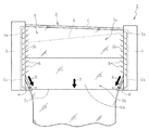
図1は、本発明の第1実施形態に係る薄板ガラス製造装置の要部を示す正面図である。なお、従来技術で説明した構成に対応する構成については同一符号を付して説明する。この薄板ガラス製造装置は、オーバーフローダウンドロー法を実行するための成形体1を備えている。 FIG. 1 is a front view showing a main part of the thin glass manufacturing apparatus according to the first embodiment of the present invention. In addition, about the structure corresponding to the structure demonstrated by the prior art, it attaches | subjects and demonstrates the same code | symbol. This thin glass manufacturing apparatus includes a molded body 1 for executing the overflow downdraw method.
成形体1は、成形体本体2と、成形体本体2の幅方向両端部にそれぞれ外嵌された一対の覆設部材3とを備えている。
The molded body 1 includes a molded body
成形体本体2は、製造される薄板ガラスの幅方向に対応する方向に沿って長尺であり、頂部にその長手方向に沿って形成されたオーバーフロー溝4と、略楔状に下方に向かって互いに漸次接近する一対の外側面部5とを有する。
The molded
この成形体本体2の頂部に形成されたオーバーフロー溝4には、溶融ガラスGが流し込まれ、両側に溢れ出た溶融ガラスGのうち、本流溶融ガラスGaが、成形体本体2の略楔状をなす両外側面部5に沿って流下する。成形体本体2の両外側面部5に沿って流下する本流溶融ガラスGaは、成形体本体2の下端部のルートと称される部分で融合一体化され、本流溶融ガラスGaから一枚の薄板ガラスが連続的に成形される。なお、融合一体化された本流溶融ガラスGaの幅方向両端部は、成形体1の下方で牽引ローラ(図示しない)等によって表裏両側から挟持されながら下方へと送られる。
The molten glass G is poured into the overflow groove 4 formed at the top of the molded
成形体本体2の外側面部5は、垂直面部5aと、傾斜面部5bとを上下に連接して構成されており、傾斜面部5bの交点が、上述のルートと称される成形体本体2の下端部5cを構成する。
The
一方、覆設部材3は、成形体本体2の幅方向両端部に外嵌される嵌合凹部3aを有している(詳細には、図5を参照)。そして、覆設部材3は、その嵌合凹部3aを成形体本体2に嵌合させた状態で、成形体本体2の幅方向両端部を覆うと共に、成形体本体2の外側面部5に沿って流下する溶融ガラスGの幅方向の広がりを規制する規制壁部3bを形成する。なお、規制壁部3bは、例えば1〜10mmの厚みを呈する。
On the other hand, the covering
更に、本実施形態の特徴的な構成として、覆設部材3の規制壁部3bには、成形体本体2の下端部5cを含む下部領域を下方から覆いながら幅方向中央部側に延出する延出部6が設けられている。そして、この延出部6の先端部を、成形体本体2の外側面部5に沿って正常に流下する本流溶融ガラスGa(図中の矢印Aで示す流れ)の流下エリアに指向させている。そのため、延出部6の先端部が、本流溶融ガラスGaの流下エリアと重複している。この延出部6の本流溶融ガラスGaの流下エリアとの重複部分は、少なくとも成形体本体2の下端部5cにおいて形成されていればよい。
Furthermore, as a characteristic configuration of the present embodiment, the regulating
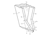
詳細には、図2に示すように、この実施形態では、延出部6は、成形体本体2の外側面部5に沿った薄肉部材(覆設部材3の規制壁部3bよりも薄い範囲で、例えば0.5〜3mmの厚み)で構成されると共に、成形体本体2の下端部に移行するに連れて、幅方向端部から幅方向中央側に漸次接近するように延出している。換言すれば、延出部6の先端部の下方側がその上方側よりも幅方向中央側に位置するように、延出部6の先端部が傾斜している。そのため、延出部6の表面に、本流溶融ガラスGaが乗り上げるようになっている。すなわち、延出部6の表面の一部が、本流溶融ガラスGaの流下エリアの一部を構成している。
Specifically, as shown in FIG. 2, in this embodiment, the extending
このように覆設部材3に延出部6を設ければ、成形体本体2の下端部5cを含む下部領域において、覆設部材3と成形体本体2との熱膨張差に起因して両者2,3の間に形成された隙間に図中の矢印B方向から侵入した分流溶融ガラスGxを延出部6によって幅方向中央側に誘導し、本流溶融ガラスGaに確実に合流させることができる。したがって、分流溶融ガラスGxが単独で成形体本体2の下端部から流下することがなく、分流溶融ガラスGxに起因した雫状ガラス(図7を参照)が形成されるという事態を確実に防止することができる。よって、本流溶融ガラスGaから分離した分流溶融ガラスGxによって、成形される薄板ガラスが汚染されたり、破損するという致命的な問題が生じるという事態を確実に防止し、安定した薄板ガラスの製造を維持することができる。
If the extending
ここで、本流溶融ガラスGaが乗り上げる延出部6の表面は、凹凸を有していることが好ましい。具体的には、延出部6の表面は、例えば、直径1〜2mmで、深さ若しくは突出高さ1〜2mmの凹部若しくは凸部が2〜3mmの間隔で点在するような表面状態であることが好ましい。このようにすれば、本流溶融ガラスGaと延出部6との間の密着性が向上するため、本流溶融ガラスGaの幅方向の収縮を抑えることができる。そのため、本流溶融ガラスGaの幅方向寸法を幅広に維持することが可能となる。
Here, it is preferable that the surface of the extending
また、延出部6は、耐熱性及び耐食性を有する金属、これらの合金、又はこれらの複合材料で形成される。具体的には、例えば、白金、白金合金、セラミック分散複合材料などによって形成される。
Moreover, the
更に、延出部6の幅方向の最大寸法L1は、10〜200mmであることが好ましく、20〜180mmであることがより好ましく、30〜160mmであることが最も好ましい。また、延出部6の高さ方向の最大寸法L2は、30mm以上であることが好ましく、30mm以上400mm以下であることがより好ましく、30mm以上200mm以下であることが最も好ましい。ただし、L1≦L2とする。
Furthermore, the maximum dimension L1 in the width direction of the extending
次に、以上のように構成された薄板ガラス製造装置によって、薄板ガラスを製造する方法について説明する。 Next, a method for manufacturing a thin glass sheet using the thin glass manufacturing apparatus configured as described above will be described.
図1に示すように、まず、図示しない供給パイプからオーバーフロー溝4の内部に溶融ガラスGを供給し、オーバーフロー溝4から成形体本体2の両側に溶融ガラスGを溢れ出させる。この成形体本体2の両側に溢れ出た溶融ガラスGのうち、本流溶融ガラスGaは、覆設部材3の規制壁部3bによって幅方向の広がりを規制されながら、両外側面部5に沿って流下して、成形体本体2の下端部で融合一体化される。この際、本流溶融ガラスGaから分離して、成形体本体2と覆設部材3との間の隙間に侵入する分流溶融ガラスGxが生じるが、この分流溶融ガラスGxは、成形体本体2の下端部を含む下部領域(図示例では、成形体本体2の下端部)において、延出部6によって下方から受け止められると共に、延出部6に沿って幅方向中央側へと誘導されて本流溶融ガラスGaと合流する。したがって、本流溶融ガラスGaと分流溶融ガラスGxとが成形体本体2の下端部において再び合流した後、成形体本体2の下端部の下方で延伸されながら冷却され、薄板ガラスが連続的に成形される。
As shown in FIG. 1, first, molten glass G is supplied into an overflow groove 4 from a supply pipe (not shown), and the molten glass G overflows from the overflow groove 4 to both sides of the molded
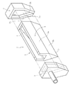
図3は、本発明の第2実施形態に係る薄板ガラス製造装置の要部を示す正面図である。この第2実施形態に係る薄板ガラス製造装置が、第1実施形態に係る薄板ガラス製造装置と相違するところは、覆設部材3に設けられた延出部6の構造にある。
FIG. 3: is a front view which shows the principal part of the sheet glass manufacturing apparatus which concerns on 2nd Embodiment of this invention. The thin glass manufacturing apparatus according to the second embodiment is different from the thin glass manufacturing apparatus according to the first embodiment in the structure of the extending
すなわち、延出部6が、その先端縁6aで本流溶融ガラスGaの幅方向の広がりを規制可能な厚肉部材で構成されている点が相違する。このようにすれば、延出部6の先端部6aが、本流溶融ガラスGaの幅方向の広がりを規制する規制壁部として機能する。そのため、延出部6によって本流溶融ガラスGaの幅方向の広がりを規制しつつ、延出部6の先端から外部に流出する分流溶融ガラスGxを本流溶融ガラスGaに確実に合流させることが可能となる。
That is, the
延出部6の幅方向の最大寸法L1や、延出部6の高さ方向の最大寸法L2の好ましい範囲は、上記の第1実施形態と同様とする。
The preferable range of the maximum dimension L1 in the width direction of the
なお、本発明は上記実施形態に限定されるものではなく、種々の形態で実施することができる。例えば、上記の実施形態では、延出部6によって成形体本体5の外側面部5の傾斜面部5bを覆う場合を図示して説明したが、延出部6は外側面部5の傾斜面5bから垂直面部5aまでを連続的に覆っていてもよい。
In addition, this invention is not limited to the said embodiment, It can implement with a various form. For example, in the above embodiment, the case where the extending
1 成形体
2 成形体本体
3 覆設部材
3a 嵌合凹部
3b 規制壁部
4 オーバーフロー溝
5 外側面部
5a 垂直面部
5b 傾斜面部
5c 下端部
6 延出部
G 溶融ガラス
Ga 本流溶融ガラス
Gx 分流溶融ガラス
DESCRIPTION OF SYMBOLS 1 Molded
Claims (8)
前記一対の覆設部材の各規制壁部に、前記成形体本体の下端部を含む下部領域を下方から覆いながら幅方向中央部側に延出する延出部を設け、前記延出部と前記成形体本体との間に隙間を空けるとともに、前記延出部の先端部を前記成形体本体の外側面部に沿って正常に流下する本流溶融ガラスの流下エリアに指向させたことを特徴とする薄板ガラス製造装置。 A molded body body that has an overflow groove at the top, and fuses and integrates the molten glass overflowing on both sides from the overflow groove along the substantially wedge-shaped outer surface portion to form a sheet glass by fusing and integrating at the lower end, and A pair of covering members that are fitted around each of the widthwise opposite ends of the molded body and that form regulating wall portions that regulate the spread in the width direction of the molten glass flowing down along the outer surface of the molded body. In a thin glass manufacturing apparatus having a molded body provided,
Each of the regulating wall portions of the pair of covering members is provided with an extending portion that extends toward the center in the width direction while covering a lower region including the lower end portion of the molded body from below, and the extending portion and the Rutotomoni a gap between the molded body, characterized in that the front end portion of the extending portion was directed to flow down the area of the mainstream molten glass flowing down normally along the outer surface of the compact body Thin glass manufacturing equipment.
Priority Applications (6)
| Application Number | Priority Date | Filing Date | Title |
|---|---|---|---|
| JP2011081961A JP5724552B2 (en) | 2011-04-01 | 2011-04-01 | Thin glass manufacturing equipment |
| PCT/JP2012/057683 WO2012137616A1 (en) | 2011-04-01 | 2012-03-26 | Glass sheet manufacturing apparatus |
| US13/429,548 US8726695B2 (en) | 2011-04-01 | 2012-03-26 | Manufacturing apparatus for a thin glass sheet |
| KR1020137025475A KR101860736B1 (en) | 2011-04-01 | 2012-03-26 | Glass sheet manufacturing apparatus |
| CN201280004756.2A CN103313945B (en) | 2011-04-01 | 2012-03-26 | Sheet glass manufacturing installation |
| TW101110952A TWI519490B (en) | 2011-04-01 | 2012-03-29 | Sheet glass manufacturing apparatus |
Applications Claiming Priority (1)
| Application Number | Priority Date | Filing Date | Title |
|---|---|---|---|
| JP2011081961A JP5724552B2 (en) | 2011-04-01 | 2011-04-01 | Thin glass manufacturing equipment |
Publications (3)
| Publication Number | Publication Date |
|---|---|
| JP2012214349A JP2012214349A (en) | 2012-11-08 |
| JP2012214349A5 JP2012214349A5 (en) | 2014-01-30 |
| JP5724552B2 true JP5724552B2 (en) | 2015-05-27 |
Family
ID=46969017
Family Applications (1)
| Application Number | Title | Priority Date | Filing Date |
|---|---|---|---|
| JP2011081961A Active JP5724552B2 (en) | 2011-04-01 | 2011-04-01 | Thin glass manufacturing equipment |
Country Status (6)
| Country | Link |
|---|---|
| US (1) | US8726695B2 (en) |
| JP (1) | JP5724552B2 (en) |
| KR (1) | KR101860736B1 (en) |
| CN (1) | CN103313945B (en) |
| TW (1) | TWI519490B (en) |
| WO (1) | WO2012137616A1 (en) |
Families Citing this family (16)
| Publication number | Priority date | Publication date | Assignee | Title |
|---|---|---|---|---|
| CN104428260B (en) * | 2012-08-24 | 2017-02-15 | 日本电气硝子株式会社 | Sheet glass manufacturing apparatus and sheet glass manufacturing method |
| JP5797294B2 (en) | 2013-03-29 | 2015-10-21 | AvanStrate株式会社 | Manufacturing method of glass plate |
| WO2014163063A1 (en) | 2013-04-01 | 2014-10-09 | 日本電気硝子株式会社 | Sheet glass forming method and sheet glass forming device |
| TWI656022B (en) * | 2013-11-13 | 2019-04-11 | 美商康寧公司 | Laminated glass article and method of manufacturing same |
| TWI675805B (en) * | 2014-09-30 | 2019-11-01 | 美商康寧公司 | Isopipe end flow dam |
| CN107001099A (en) * | 2014-10-06 | 2017-08-01 | 康宁股份有限公司 | The method and the equipment for it being modified to melten glass stream |
| JP6679585B2 (en) * | 2014-10-07 | 2020-04-15 | ショット アクチエンゲゼルシャフトSchott AG | Laminated glass with increased strength |
| EP3377453A1 (en) | 2015-11-20 | 2018-09-26 | Corning Incorporated | Laminated glass ribbons and apparatuses for forming laminated glass ribbons |
| US20180327299A1 (en) * | 2015-11-20 | 2018-11-15 | Corning Incorporated | Apparatus and method for forming glass ribbon |
| US9840431B2 (en) * | 2016-01-11 | 2017-12-12 | Corning Incorporated | Methods and apparatuses for supporting forming bodies of glass forming apparatuses |
| KR102490511B1 (en) * | 2017-04-28 | 2023-01-19 | 코닝 인코포레이티드 | Edge directors with internal heating |
| WO2019104039A2 (en) * | 2017-11-22 | 2019-05-31 | Corning Incorporated | Apparatuses including edge directors for forming glass ribbons |
| JP7488509B2 (en) * | 2020-06-18 | 2024-05-22 | 日本電気硝子株式会社 | Glass article manufacturing apparatus and manufacturing method thereof |
| JP7488510B2 (en) | 2020-06-18 | 2024-05-22 | 日本電気硝子株式会社 | Glass article manufacturing apparatus and manufacturing method thereof |
| JP7495662B2 (en) | 2020-07-16 | 2024-06-05 | 日本電気硝子株式会社 | Method for manufacturing glass articles |
| JP2024039850A (en) * | 2022-09-12 | 2024-03-25 | Agc株式会社 | glass forming equipment |
Family Cites Families (18)
| Publication number | Priority date | Publication date | Assignee | Title |
|---|---|---|---|---|
| US3451798A (en) * | 1966-04-04 | 1969-06-24 | Corning Glass Works | Sheet glass edge control device |
| US3537834A (en) * | 1968-08-07 | 1970-11-03 | Corning Glass Works | Maintaining sheet glass width |
| JPS63151633A (en) * | 1986-12-15 | 1988-06-24 | Hoya Corp | Device for producing plate glass |
| DE69807816T2 (en) * | 1997-11-07 | 2003-05-28 | Rohm And Haas Co., Philadelphia | Method and device for molding a plastic plate |
| JP4193115B2 (en) * | 2003-03-20 | 2008-12-10 | 日本電気硝子株式会社 | Sheet glass forming apparatus and sheet glass forming method |
| US7690221B2 (en) * | 2004-02-23 | 2010-04-06 | Corning Incorporated | Sheet width control for overflow downdraw sheet glass forming apparatus |
| JP5173434B2 (en) | 2004-12-30 | 2013-04-03 | コーニング インコーポレイテッド | Refractory material |
| KR101224666B1 (en) * | 2005-02-24 | 2013-01-21 | 코닝 인코포레이티드 | Method and apparatus for making a glass sheet |
| US20060236722A1 (en) | 2005-04-26 | 2006-10-26 | Robert Delia | Forming apparatus with extensions attached thereto used in a glass manufacturing system |
| US7409839B2 (en) * | 2005-04-29 | 2008-08-12 | Corning Incorporated | Method and apparatus for making a glass sheet |
| US7748236B2 (en) * | 2005-12-27 | 2010-07-06 | Corning Incorporated | Overflow downdraw glass forming method and apparatus |
| CN101495417B (en) * | 2006-04-28 | 2012-09-26 | 康宁股份有限公司 | Apparatus and method for forming a glass substrate with increased edge stability |
| CN101910073B (en) * | 2007-11-29 | 2014-03-12 | 康宁股份有限公司 | Creep Resistant Multilayer Refractories for Glass Manufacturing Systems |
| CN102369166B (en) * | 2009-02-26 | 2014-11-26 | 康宁股份有限公司 | Apparatus for forming glass with edge directors and methods |
| KR20120038968A (en) | 2009-07-13 | 2012-04-24 | 아사히 가라스 가부시키가이샤 | Glass plate production method and production device |
| TWI540107B (en) * | 2010-01-19 | 2016-07-01 | 康寧公司 | Apparatus and methods for fusion drawing a glass ribbon |
| US8176753B2 (en) * | 2010-02-26 | 2012-05-15 | Corning Incorporated | Methods and apparatus for reducing heat loss from an edge director |
| TWI548598B (en) * | 2011-02-28 | 2016-09-11 | 康寧公司 | Fusion draw apparatus and methods |
-
2011
- 2011-04-01 JP JP2011081961A patent/JP5724552B2/en active Active
-
2012
- 2012-03-26 US US13/429,548 patent/US8726695B2/en active Active
- 2012-03-26 WO PCT/JP2012/057683 patent/WO2012137616A1/en not_active Ceased
- 2012-03-26 KR KR1020137025475A patent/KR101860736B1/en active Active
- 2012-03-26 CN CN201280004756.2A patent/CN103313945B/en active Active
- 2012-03-29 TW TW101110952A patent/TWI519490B/en active
Also Published As
| Publication number | Publication date |
|---|---|
| JP2012214349A (en) | 2012-11-08 |
| US20120272688A1 (en) | 2012-11-01 |
| US8726695B2 (en) | 2014-05-20 |
| CN103313945A (en) | 2013-09-18 |
| TWI519490B (en) | 2016-02-01 |
| WO2012137616A1 (en) | 2012-10-11 |
| KR101860736B1 (en) | 2018-05-24 |
| KR20140015411A (en) | 2014-02-06 |
| TW201247562A (en) | 2012-12-01 |
| CN103313945B (en) | 2015-12-23 |
Similar Documents
| Publication | Publication Date | Title |
|---|---|---|
| JP5724552B2 (en) | Thin glass manufacturing equipment | |
| KR102071373B1 (en) | Device for manufacturing sheet glass, and method for manufacturing sheet glass | |
| KR101818774B1 (en) | Overflow down-draw with improved glass melt velocity and thickness distribution | |
| KR20090016564A (en) | Apparatus and method for forming organic substrates with increased edge stability | |
| TWI889692B (en) | Apparatus and method for producing glass ribbons | |
| JP2008501608A (en) | Isopipe mass distribution for forming glass substrates | |
| JP6331148B2 (en) | Sheet glass forming method and sheet glass forming apparatus | |
| JP2018534232A (en) | Laminated glass ribbon and laminated glass ribbon forming apparatus | |
| JP5482255B2 (en) | Method for supplying molten glass metering wheel and molten glass. | |
| KR20130038248A (en) | Thin glass sheet manufacturing device and method | |
| KR20210042088A (en) | Manufacturing method of plate glass | |
| JP2013184876A (en) | Apparatus and method for forming thin sheet glass | |
| JP2017088446A (en) | Manufacturing apparatus for thin sheet glass and manufacturing method thereof | |
| WO2011122195A1 (en) | Thin glass plate and process for production thereof | |
| JP2013184877A (en) | Apparatus and method for forming thin sheet glass | |
| JP2012171836A (en) | Flat glass manufacturing apparatus and flat glass manufacturing method | |
| JP6691690B2 (en) | Sheet glass manufacturing apparatus and manufacturing method thereof | |
| JP5704505B2 (en) | Sheet glass manufacturing apparatus and sheet glass manufacturing method | |
| JP2019112255A (en) | Apparatus and method for manufacturing glass article | |
| JP2017100895A (en) | Nozzle device and production method of glass article | |
| KR20200059571A (en) | Apparatus for manufacturing glass |
Legal Events
| Date | Code | Title | Description |
|---|---|---|---|
| A521 | Written amendment |
Free format text: JAPANESE INTERMEDIATE CODE: A523 Effective date: 20131204 |
|
| A621 | Written request for application examination |
Free format text: JAPANESE INTERMEDIATE CODE: A621 Effective date: 20131204 |
|
| A131 | Notification of reasons for refusal |
Free format text: JAPANESE INTERMEDIATE CODE: A131 Effective date: 20150105 |
|
| A521 | Written amendment |
Free format text: JAPANESE INTERMEDIATE CODE: A523 Effective date: 20150202 |
|
| TRDD | Decision of grant or rejection written | ||
| A01 | Written decision to grant a patent or to grant a registration (utility model) |
Free format text: JAPANESE INTERMEDIATE CODE: A01 Effective date: 20150303 |
|
| A61 | First payment of annual fees (during grant procedure) |
Free format text: JAPANESE INTERMEDIATE CODE: A61 Effective date: 20150316 |
|
| R150 | Certificate of patent or registration of utility model |
Ref document number: 5724552 Country of ref document: JP Free format text: JAPANESE INTERMEDIATE CODE: R150 |