JP5723366B2 - Control method of powered air purification artificial respiration apparatus - Google Patents
Control method of powered air purification artificial respiration apparatus Download PDFInfo
- Publication number
- JP5723366B2 JP5723366B2 JP2012524824A JP2012524824A JP5723366B2 JP 5723366 B2 JP5723366 B2 JP 5723366B2 JP 2012524824 A JP2012524824 A JP 2012524824A JP 2012524824 A JP2012524824 A JP 2012524824A JP 5723366 B2 JP5723366 B2 JP 5723366B2
- Authority
- JP
- Japan
- Prior art keywords
- air
- ambient
- fan
- air density
- user
- Prior art date
- Legal status (The legal status is an assumption and is not a legal conclusion. Google has not performed a legal analysis and makes no representation as to the accuracy of the status listed.)
- Active
Links
Images


Classifications
-
- A—HUMAN NECESSITIES
- A62—LIFE-SAVING; FIRE-FIGHTING
- A62B—DEVICES, APPARATUS OR METHODS FOR LIFE-SAVING
- A62B18/00—Breathing masks or helmets, e.g. affording protection against chemical agents or for use at high altitudes or incorporating a pump or compressor for reducing the inhalation effort
- A62B18/006—Breathing masks or helmets, e.g. affording protection against chemical agents or for use at high altitudes or incorporating a pump or compressor for reducing the inhalation effort with pumps for forced ventilation
-
- A—HUMAN NECESSITIES
- A62—LIFE-SAVING; FIRE-FIGHTING
- A62B—DEVICES, APPARATUS OR METHODS FOR LIFE-SAVING
- A62B7/00—Respiratory apparatus
- A62B7/10—Respiratory apparatus with filter elements
-
- F—MECHANICAL ENGINEERING; LIGHTING; HEATING; WEAPONS; BLASTING
- F04—POSITIVE - DISPLACEMENT MACHINES FOR LIQUIDS; PUMPS FOR LIQUIDS OR ELASTIC FLUIDS
- F04D—NON-POSITIVE-DISPLACEMENT PUMPS
- F04D25/00—Pumping installations or systems
- F04D25/02—Units comprising pumps and their driving means
- F04D25/08—Units comprising pumps and their driving means the working fluid being air, e.g. for ventilation
-
- F—MECHANICAL ENGINEERING; LIGHTING; HEATING; WEAPONS; BLASTING
- F04—POSITIVE - DISPLACEMENT MACHINES FOR LIQUIDS; PUMPS FOR LIQUIDS OR ELASTIC FLUIDS
- F04D—NON-POSITIVE-DISPLACEMENT PUMPS
- F04D27/00—Control, e.g. regulation, of pumps, pumping installations or pumping systems specially adapted for elastic fluids
- F04D27/004—Control, e.g. regulation, of pumps, pumping installations or pumping systems specially adapted for elastic fluids by varying driving speed
-
- F—MECHANICAL ENGINEERING; LIGHTING; HEATING; WEAPONS; BLASTING
- F04—POSITIVE - DISPLACEMENT MACHINES FOR LIQUIDS; PUMPS FOR LIQUIDS OR ELASTIC FLUIDS
- F04D—NON-POSITIVE-DISPLACEMENT PUMPS
- F04D27/00—Control, e.g. regulation, of pumps, pumping installations or pumping systems specially adapted for elastic fluids
- F04D27/02—Surge control
- F04D27/0261—Surge control by varying driving speed
-
- Y—GENERAL TAGGING OF NEW TECHNOLOGICAL DEVELOPMENTS; GENERAL TAGGING OF CROSS-SECTIONAL TECHNOLOGIES SPANNING OVER SEVERAL SECTIONS OF THE IPC; TECHNICAL SUBJECTS COVERED BY FORMER USPC CROSS-REFERENCE ART COLLECTIONS [XRACs] AND DIGESTS
- Y02—TECHNOLOGIES OR APPLICATIONS FOR MITIGATION OR ADAPTATION AGAINST CLIMATE CHANGE
- Y02B—CLIMATE CHANGE MITIGATION TECHNOLOGIES RELATED TO BUILDINGS, e.g. HOUSING, HOUSE APPLIANCES OR RELATED END-USER APPLICATIONS
- Y02B30/00—Energy efficient heating, ventilation or air conditioning [HVAC]
- Y02B30/70—Efficient control or regulation technologies, e.g. for control of refrigerant flow, motor or heating
Description
本発明は、動力付き空気浄化人工呼吸装置(PAPR)で使用するための送風機システム、及び送風機システムの制御方法に関する。 The present invention relates to a blower system for use in a powered air purification artificial respirator (PAPR) and a method for controlling the blower system.
潜在的に健康に有害な若しくは害を及ぼす粉塵、煙、若しくはガスが存在することが知られている、又はその危険性のある地域で作業をする場合、作業者は人工呼吸装置を使用するのが常である。そのような状況で使用される人工呼吸装置の一般的なタイプは、動力付き空気浄化人工呼吸装置(PAPR)である。PAPRは、空気の強制的な流れを人工呼吸装置のユーザーに供給するために、電動モータによって作動するファンを備える送風機システムを有する。タービンユニットはハウジングであり、このハウジングは、典型的には、送風機システムを収容し、かつ、フィルタを送風機システムに接続するように適合される。空気は、送風機システムによってフィルタを通して引き込まれ、タービンユニットから呼吸管を通ってヘッドピース(headpiece)(例えば、ヘルメット又はヘッドトップ(headtop))へと送られて、濾過された空気がユーザーの呼吸ゾーン(鼻及び口の周囲領域)に提供される。PAPRの送風機システムはまた、ファンを駆動する電力を調節するための電子制御ユニットを備える。典型的には、単一電力供給装置、例えば、電池が、ファン及び電子制御ユニットの両方に電力を提供する。 When working in an area known or at risk for dust, smoke, or gas that is potentially harmful or harmful to health, workers use ventilators. Is always. A common type of ventilator used in such situations is a powered air purifying ventilator (PAPR). PAPR has a blower system with a fan that is actuated by an electric motor to provide a forced flow of air to the user of the ventilator. The turbine unit is a housing, which is typically adapted to house the blower system and connect the filter to the blower system. Air is drawn through the filter by the blower system and sent from the turbine unit through the breathing tube to a headpiece (eg, helmet or headtop) where the filtered air is in the user's breathing zone. Provided in the area surrounding the nose and mouth. The PAPR blower system also includes an electronic control unit for adjusting the power driving the fan. Typically, a single power supply, such as a battery, provides power to both the fan and the electronic control unit.
送風機からの実質的に一定体積の空気流を維持するのを目的として、電子制御ユニットを使用して、例えば、電動モータへの電力を制御することができる。用語「体積空気流」は、任意の一時点でユーザーに提供される空気の質量ではなく、任意の一時点でユーザーに提供される空気容量を示す。ユーザーは、指定されたレベルの呼吸保護が維持されるのを確実にするのに十分な空気流を必要とする。しかしながら、高すぎる空気流は、不快感や、ヘッドピース内部のユーザーの頭部の過剰冷却を引き起こし得る。低すぎる空気流は、ユーザーの呼吸ゾーン内への汚染物質の進入を引き起こし得る。電子制御ユニットはまた、例えば、空気流が指定レベルを下回っていることをユーザーに警告するため、又は、フィルタが粉塵でふさがれていて交換する必要があることをユーザーに警告するために、ユーザーに対し警報を発するのに使用されてもよい。モータ電圧、モータ電流、及びモータ速度の組み合わせに基づいて、PAPR送風機システムのファンモータへの電力を制御することが、以前に提案されている。この種の送風機制御システムの例は、米国特許出願第2008/0127979号及び米国特許第7,244,106号に記載されている。 For the purpose of maintaining a substantially constant volume of air flow from the blower, an electronic control unit can be used, for example, to control the power to the electric motor. The term “volumetric air flow” refers to the volume of air provided to the user at any one time, not the mass of air provided to the user at any one time. The user needs sufficient airflow to ensure that the specified level of respiratory protection is maintained. However, air flow that is too high can cause discomfort and overcooling of the user's head inside the headpiece. Too low airflow can cause contaminants to enter the user's breathing zone. The electronic control unit can also be used, for example, to alert the user that the airflow is below a specified level, or to alert the user that the filter is dusty and needs to be replaced. May be used to issue an alarm. It has previously been proposed to control the power to the fan motor of a PAPR blower system based on a combination of motor voltage, motor current, and motor speed. Examples of this type of blower control system are described in US Patent Application No. 2008/0127979 and US Patent No. 7,244,106.
米国特許出願第2008/0127979号は、特定のモータ速度及び対応の空気流を生成するための制御変数としてパルス幅変調(PWM)比を使用する電子制御システムを記載している。PWM比は、電子制御システムに記憶された検量線から読み出される。 US Patent Application No. 2008/0127979 describes an electronic control system that uses a pulse width modulation (PWM) ratio as a control variable to generate a specific motor speed and corresponding airflow. The PWM ratio is read from a calibration curve stored in the electronic control system.
米国特許第7,244,106号は、モータの電力消費及びファンの速度を検出し、これを、ファンからの所与の空気流に関するモータの特性曲線(記憶装置に記憶されている)と比較する制御ユニットを記載している。この特性曲線から逸脱する場合、制御ユニットは、モータに供給される電圧変化を調節して、一定の空気流を維持する。 U.S. Pat. No. 7,244,106 detects motor power consumption and fan speed and compares it to a motor characteristic curve (stored in memory) for a given airflow from the fan. The control unit is described. When deviating from this characteristic curve, the control unit adjusts the voltage change supplied to the motor to maintain a constant air flow.
濾過された空気の所定の体積空気流は、通常、PAPRのユーザーに供給されて、粒子又はガスが呼吸ゾーンに進入することからの一定レベルの保護を提供するように意図されている。現在入手可能なシステムは、提供される空気が少なすぎる状態に陥るといった危険を冒さず、実際に必要なものよりはるかに高い体積空気流を提供する場合が多い。より高い空気流を提供するためにより多くの電力が消費されるので、より高い空気流とは、通常、充電までの電池寿命が低減すること、又はより大きな電池が必要であることを意味する。高い空気流を提供することによって、過剰な汚染空気がフィルタを通って移動し、その結果不必要な濾過及びフィルタの早すぎる目詰まり又は飽和を引き起こすので、フィルタ寿命もまた短縮する。フィルタは消耗品であり、PAPRの耐用年数にわたって何度も交換することが必要であるので、これによりランニングコストがより高くなり得る。更なる問題は、多くのPAPRでは、空気流が所定のレベルを下回ったという事実をユーザーに警告する空気流下限警報器(low airflow alarm)が必要であるということである。不正確な空気流測定又は制御システムが使用されている場合、ユーザーが常に安全であることを確実にするために、警報レベルは人為的に高いレベルに設定されていることが多い。このことは、結果として、フィルタが必要以上に頻繁に交換される、又は、ユーザーが不必要に作業場を離れる原因となり得る。 A predetermined volume air flow of filtered air is usually provided to the PAPR user and is intended to provide a level of protection from particles or gas entering the breathing zone. Currently available systems do not run the risk of providing too little air and often provide much higher volume airflow than is actually needed. Higher airflow usually means that the battery life to charge is reduced or that a larger battery is needed because more power is consumed to provide a higher airflow. By providing a high air flow, filter life is also shortened because excess contaminated air travels through the filter, resulting in unnecessary filtration and premature clogging or saturation of the filter. This can lead to higher running costs as the filter is a consumable and needs to be replaced many times over the life of the PAPR. A further problem is that many PAPRs require a low airflow alarm that warns the user that the airflow has fallen below a predetermined level. When an inaccurate airflow measurement or control system is used, the alarm level is often set to an artificially high level to ensure that the user is always safe. This can result in the filter being replaced more frequently than necessary or causing the user to leave the workplace unnecessarily.
したがって、空気流が特定の体積の空気流となるようにより正確に制御することにより、充電までの電池寿命の改善又はより小さくかつ軽量な電池の使用、フィルタ寿命の改善、及び早すぎる空気流下限警報の低減をもたらすことができる。これら要因の全ては、改善されたユーザー生産性をもたらすことができる。 Therefore, by more accurately controlling the air flow to be a specific volume of air flow, improving battery life to charge or using smaller and lighter batteries, improving filter life, and premature airflow lower bound Alarm reduction can be provided. All of these factors can result in improved user productivity.
したがって、そのような問題を最小限に抑えると同時に、PAPRの全体的な機能性を維持する又は改善する、PAPRの制御方法を用いることが望ましい。 It is therefore desirable to use a PAPR control method that minimizes such problems while maintaining or improving the overall functionality of the PAPR.
本発明は、実質的に一定体積の空気流をユーザーに供給するための動力付き空気浄化人工呼吸装置の送風機システムを制御する方法を提供することにより、これらの問題に対処すること目的とし、このシステムは、濾過された空気の強制的な流れをユーザーに供給するために、電動モータによって作動され、電子制御ユニットによって制御されるファンと、電動モータの電気的特性に関する少なくとも2つの較正値をその中に記憶する電子制御ユニットとを備え、該方法は、(a)周囲空気密度又は(b)周囲温度及び周囲気圧の一方を決定する工程と、決定及び少なくとも2つの較正値に応答して、電動モータの電気的特性を調整する工程と、を含む。 The present invention aims to address these problems by providing a method for controlling a blower system of a powered air purification ventilator for supplying a substantially constant volume of airflow to a user. The system provides at least two calibration values for the electrical characteristics of the electric motor and a fan operated by an electric motor and controlled by an electronic control unit to provide a forced flow of filtered air to the user. In response to the determination and at least two calibration values, the method comprising: (a) determining one of ambient air density or (b) ambient temperature and atmospheric pressure; Adjusting the electrical characteristics of the electric motor.
送風機を制御するときの1つ以上の周囲空気特性を考慮することにより、ユーザーに供給される体積空気流をより正確に制御することができるので、PAPRのより良好な機能性を提供することができる。 By taking into account one or more ambient air characteristics when controlling the blower, the volumetric air flow supplied to the user can be more accurately controlled, thus providing better functionality of the PAPR. it can.
本発明はまた、電動モータによって作動するファンと、ファンの速度と、ファンからの選択された実質的に一定体積の空気流に関して適用されたモータの電気的特性との間の所定の相関関係にしたがって、モータの電気的特性を調整するように動作可能な電子制御ユニットと、を備える、空気浄化人工呼吸装置の送風機システムを提供し、このシステムは、電子制御ユニットと連通するように適合され、かつ、(a)周囲空気密度又は(b)周囲温度及び周囲気圧の一方を決定するように配置された、少なくとも1つのセンサを更に備え、この電子制御ユニットは、モータの電気的特性を調整して、ファンからの選択された実質的に一定体積の空気流を維持するために、(a)周囲空気密度又は(b)周囲温度及び周囲気圧の決定に応答して動作可能である。 The present invention also provides for a predetermined correlation between a fan operated by an electric motor, fan speed, and motor electrical characteristics applied for a selected substantially constant volume airflow from the fan. Accordingly, an air purification ventilator blower system is provided comprising an electronic control unit operable to adjust the electrical characteristics of the motor, the system being adapted to communicate with the electronic control unit; And further comprising at least one sensor arranged to determine one of (a) ambient air density or (b) ambient temperature and pressure, wherein the electronic control unit adjusts the electrical characteristics of the motor. In response to determining (a) ambient air density or (b) ambient temperature and pressure to maintain a selected substantially constant volume of airflow from the fan It is possible to work.
本発明の他の特徴は、添付の従属請求項から明らかになるであろう。 Other features of the invention will be apparent from the appended dependent claims.
例示のみを目的として、添付の図面を参照しながら、以下に本発明の実施形態を説明す
る。
For purposes of illustration only, embodiments of the invention are described below with reference to the accompanying drawings.
本発明は、PAPRが高地又は海抜以下で使用される場合に遭遇する上記の問題が、周囲空気密度の変化によって引き起こされるという認識に基づいている。周囲気圧、したがって周囲空気密度は、高地又は海抜以下で作業する場合に著しく変化し得る。周囲空気密度の変化は、周囲温度又は周囲気圧の正常変動からも生じ得る。本発明は、周囲空気密度を考慮することによって、PAPRユーザーに供給される体積空気流をより正確に制御できるようにし、したがって、PAPRのより良好な機能性を提供できるようにする。これは、PAPRを動かす電動モータの電圧、電流、又は電力などの電気的特性を、所定の較正手順にしたがって変化させることによって行われる。 The present invention is based on the recognition that the above problems encountered when PAPR is used at high altitudes or below sea level are caused by changes in ambient air density. Ambient pressure, and hence ambient air density, can vary significantly when working at high altitudes or below sea level. Changes in ambient air density can also result from normal fluctuations in ambient temperature or pressure. The present invention allows for more precise control of the volumetric air flow supplied to PAPR users by taking into account the ambient air density, thus allowing better functionality of PAPR to be provided. This is done by changing the electrical characteristics such as voltage, current, or power of the electric motor that drives the PAPR according to a predetermined calibration procedure.
用語「周囲」とは、本明細書では、ユーザーが受ける空気密度、温度、圧力、又は湿度を説明するために用いられる。周囲空気密度は、例えば、周囲気圧、周囲温度、及び周囲湿度の影響を受ける。これらの要因のそれぞれが周囲空気密度に与える影響の程度は異なっており、通常は気圧が最も大きな影響を有する。気温及び湿度の影響は少ないと考えられているが、周囲空気密度及び体積空気流を決定する際には、これらの要因もなお考慮に入れてもよい。 The term “ambient” is used herein to describe the air density, temperature, pressure, or humidity experienced by a user. Ambient air density is affected by, for example, ambient pressure, ambient temperature, and ambient humidity. The degree of influence of each of these factors on the ambient air density is different, and atmospheric pressure usually has the greatest influence. Although the effects of temperature and humidity are believed to be small, these factors may still be taken into account when determining ambient air density and volumetric airflow.
用語「湿度」は、絶対湿度、比湿、又は相対湿度のいずれかを意味するものと受け取られ得る。絶対湿度は、特定体積の空気中の水量と定義される。比湿は、水蒸気と空気との比と定義される。相対湿度は、空気と水蒸気のガス状混合物中の水蒸気の分圧と、所定の温度における水の飽和蒸気圧との比と定義される。絶対湿度値、比湿値、又は相対湿度値のいずれかの測定は、ユーザーの要望及び周囲条件に従い必要に応じて行われてもよい。 The term “humidity” may be taken to mean either absolute humidity, specific humidity, or relative humidity. Absolute humidity is defined as the amount of water in a specific volume of air. Specific humidity is defined as the ratio of water vapor to air. Relative humidity is defined as the ratio of the partial pressure of water vapor in the gaseous mixture of air and water vapor to the saturated vapor pressure of water at a given temperature. The measurement of either absolute humidity value, specific humidity value, or relative humidity value may be performed as needed according to user requirements and ambient conditions.
単なる例として、PAPRが予測可能に使用され得る範囲内での、周囲気圧、周囲温度及び周囲湿度の影響としては、次が挙げられる。 By way of example only, the effects of ambient pressure, ambient temperature, and ambient humidity within a range where PAPR can be used predictably include the following.
周囲気圧−例えば、海抜ゼロ地点の1100mbarから、例えば、海抜2500メートルの750mbarへと大気圧を変化させることにより、空気密度は初期空気密度の約68%へと減少することになる。 Ambient pressure—For example, by changing the atmospheric pressure from 1100 mbar at sea level to 750 mbar at 2500 meters above sea level, the air density will be reduced to about 68% of the initial air density.
周囲温度−気温を0℃から最高50℃へと変化させることにより、空気密度は初期空気密度の約84%へと減少することになる。 By changing the ambient temperature-temperature from 0 ° C. up to 50 ° C., the air density will be reduced to about 84% of the initial air density.
周囲湿度−0℃における周囲湿度、相対湿度RHを、0% RHから100% RHへと変化させることにより、空気密度は初期空気密度の約99.7%へと減少することになり、25℃では空気密度は初期空気密度の約98.8%へと減少することになり、また50℃では空気密度は初期空気密度の約96.5%へと減少することになる。 By changing the ambient humidity and the relative humidity RH at −0 ° C. from 0% RH to 100% RH, the air density is reduced to about 99.7% of the initial air density. Then, the air density will decrease to about 98.8% of the initial air density, and at 50 ° C., the air density will decrease to about 96.5% of the initial air density.
したがって、周囲気圧のみに基づいて空気密度補償を適用することにより、かなりの偏差及び不正確さを補償することができる。圧力及び温度の両方に基づく補償は、精度を更に改善する。湿度、温度、及び圧力に基づく補償は、最良の精度をもたらすが、温度及び圧力よりわずかに優れているだけである。 Thus, by applying air density compensation based only on ambient pressure, significant deviations and inaccuracies can be compensated. Compensation based on both pressure and temperature further improves accuracy. Compensation based on humidity, temperature, and pressure provides the best accuracy, but only slightly better than temperature and pressure.
以下に記載される実施形態のそれぞれは、図1に示されるようにタービンを採用している。図1は、動力付き空気浄化人工呼吸装置の概略図である。PAPRは、ヘッドピース1と、タービンユニット2と、呼吸管3と、フィルタ4と、ベルト5とを備えている。ヘッドピース1は、ユーザー6の頭部に着用される。ヘッドピース1は、ユーザー6の頭部を少なくとも部分的に囲んで、呼吸ゾーン7、即ち、ユーザーの鼻及び口の周囲部位を形成し、濾過された空気は、この呼吸ゾーン7に向けられる。タービンユニット2は、ユーザーの胴体の周囲に固定できるように、ベルト5に取り付けられてもよい。タービンユニット2は送風機システム(図示せず)を収容し、この送風機システムは、ファン(図示せず)を使用してPAPRシステムを通して空気を引き出す。タービンユニット2は、タービンユニット2の排気口8とヘッドピース1の吸気口9との間に接続されている呼吸管3を通して、空気をヘッドピース1に供給する。タービンユニット2にはフィルタ4が装着されており、このフィルタ4は、空気流路内に存在する(好ましくは送風機のファン開口部の上流に配置される)ように、タービンユニットの内部にあるか、又は図1に示されるようにタービンユニットに取り付けられるかのいずれかであり得る。フィルタ4を備える目的は、空気がユーザー6に供給される前に、周囲空気から粒子及び/又はガス及び/又は蒸気を除去することである。タービンユニット2に取り付けられた電池パック10は、電子制御ユニット23及びモータ22(共に、以下に論じられる図2に示される)に電力を供給する。
Each of the embodiments described below employs a turbine as shown in FIG. FIG. 1 is a schematic view of a powered air purification artificial respiration apparatus. The PAPR includes a head piece 1, a
以下は、本発明の第1の実施形態による送風機システムがどのように動作するかを示す。以下の実施例において、PAPRの構成部品は、図1及び図2を参照して上述されたものであると仮定することができる。 The following shows how the blower system according to the first embodiment of the present invention operates. In the following examples, it can be assumed that the components of the PAPR are those described above with reference to FIGS.
図2は、本発明の第1の実施形態による送風機システムのブロック図を示す。この送風機システムは、図1に示されるタービンユニット2内に収容される。本発明のこの実施形態によると、送風機20は、吸気口18と排気口19とを有するハウジング17を備える。送風機20は、モータ22によって駆動される複数の羽根16を有するファン21を更に備える。送風機20は電子制御ユニット23によって制御され、この電子制御ユニット23は、モータ22に提供される電力を調節する。
FIG. 2 shows a block diagram of a blower system according to the first embodiment of the present invention. This blower system is accommodated in the
ユーザー6が吸い込むときに、ユーザー6が容易かつ正常に呼吸するのに十分なだけの濾過された空気が利用可能であり、また、潜在的に汚染された周囲空気が吸い込まれないように、所定の、実質的に一定体積の空気流がユーザーの呼吸ゾーン7に供給されるのが望ましい。実質的に一定体積の空気流は、好ましくは、所望の又は所定の空気流からの偏差が、毎分−5〜+15リットルの範囲である空気流量であるが、これに限定されない。
To ensure that enough filtered air is available for
特定の体積空気流量で実質的に一定体積の空気流を達成するためには、空気流が既知でなくてはならない、又は、様々な作動パラメータと所要の空気流との間の相関関係が既知でなくてはならない。離散空気流センサ(discrete airflow sensor)を使用して、体積空気流をモニタすることが可能である。しかしながら、本発明において、以下に記載されるように、ファン又はモータ速度、モータ電圧、モータ電流、及びモータ電力といったファン21及びモータ22の種々の作動パラメータを用いて、体積空気流を決定できることが見出された。
In order to achieve a substantially constant volume of airflow at a specific volumetric airflow, the airflow must be known or the correlation between various operating parameters and the required airflow is known It must be. A discrete airflow sensor can be used to monitor volumetric airflow. However, in the present invention, as described below, volumetric airflow can be determined using various operating parameters of fan 21 and
図2を更に参照すると、送風機システムは電子制御ユニット23を備え、この電子制御ユニット23は、実質的に均一な、好ましくは一定の体積空気流がヘッドピース1に送られるのを維持するように機能する。電子制御ユニット23は、情報を算出するための、単一チップ・マイクロコントローラなどのマイクロプロセッサ装置24と、情報、例えば、較正データを記憶するための、フラッシュRAMなどの記憶装置25と、モータ電流センサ及びファン速度センサなどのセンサからデータを受信するための、センサ入力受信機26a、26b、26cと、モータ22、及びPAPRに含まれてもよいブザー又は発光ダイオードなどのあらゆる警報器又は状態表示器に電力を提供するための、パルス幅変調コントローラチップなどの出力制御装置27と、を備える。電子制御ユニット23の記憶装置25は、固定記憶装置及び一時記憶装置といった2つの部分を有する。固定記憶装置には、例えば、製造時に、マイクロプロセッサ24が算出及び手順を実行するのを可能にするアルゴリズム及びプログラム、並びに工場較正手順からの較正情報を含むデータが取り込まれる。一時記憶装置は、センサ読取り値などのデータ及び情報、並びに、タービンユニット2の起動及び運転中に収集されるファン作動パラメータデータを記憶するために使用される。必要に応じて、タービンユニット2の電源が切られるときに、このデータは消去されてもよい。
Still referring to FIG. 2, the blower system includes an
3相の矩形波駆動ブラシレス直流モータ22を使用して、送風機20のファン21を駆動してもよい。次の等式:EQ.1、EQ.2及びEQ.3は周知であり、かかるモータの主要パラメータ間の関係を示す。

上で説明したように、送風機20は、フィルタ4(1つ又は複数)を通して空気を移動させて、この空気をユーザー6に供給するために使用されるファン21を備える。図に示されるファン21は、しばしば遠心ファン又はラジアルファン(radial fan)として知られるタイプのファンであり、即ち、空気はファン軸の方向にファンに入り、ファンに対して半径方向に出て行く。
As described above, the
次のファン法則方程式は、ファン速度及び空気密度が変化した場合に、ファン21の性能がどのように変化するかを示す。
実質的に一定体積の空気流を維持するために、較正点のファン速度要素は不変でなければならないことが、等式EQ.4からわかる。
n2=n1 (EQ.8)
In order to maintain a substantially constant volume of air flow, the fan speed factor at the calibration point must be unchanged, equation EQ. 4
n 2 = n 1 (EQ.8)
更に、等式EQ.1、EQ.2、EQ.3、及びEQ.6を組み合わせることで、空気密度が変化したときに、較正点の印加モータ電圧要素をどのように動かしたらよいかを表す。
結論として、周囲空気密度の変化を補償するために、較正点のファン速度要素を変更する必要がないことがわかる(等式EQ.8参照)。しかしながら、較正点の印加モータ電圧要素は、周囲空気密度が変化する場合、等式EQ.9及びEQ.10にしたがって変更される必要がある。 In conclusion, it can be seen that it is not necessary to change the fan speed factor at the calibration point to compensate for changes in ambient air density (see equation EQ.8). However, the applied motor voltage element at the calibration point is equal to the equation EQ. 9 and EQ. Need to be changed according to 10.
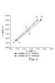
図3は、本発明の第1の実施形態による送風機システムの電子制御ユニットの較正チャートを示している。これは、実質的に一定体積の空気流を決定する過程で用いられる。電子制御ユニット23は、ファン速度と印加モータ電圧との間の正比例関係を示す較正チャート30を参照する。所定の実質的に一定体積の空気流は、2つの較正点である高31及び低32で示されている。各較正点は、印加モータ電圧及びファン速度に関する情報を含む。実質的に一定体積の空気流を維持するために、例えば、フィルタ4(1つ又は複数)が粉塵及び煙で次第に詰まり、そのため送風機20の性能が変化する場合、電子制御ユニット23は、2つの較正点31、32の間の線33に沿って追尾する。これは、ルックアップテーブル又は他のデータ配列を用いて行われてもよい。電子制御ユニットは、センサ28を使用してファン速度を測定し、これを較正線と比較した後、所定の体積空気流を維持するために、適切なモータ電圧29を印加する。
FIG. 3 shows a calibration chart of the electronic control unit of the blower system according to the first embodiment of the present invention. This is used in the process of determining a substantially constant volume of air flow. The
本発明では、較正点、したがって追尾線は、ある特定の空気密度にとって最適であるという認識が利用されている。空気密度を測定することにより、実際の空気密度を明らかにし、かつ実質的に一定体積の空気流を維持するために、較正点を適切に移動させることができる。 In the present invention, the recognition is utilized that the calibration point, and thus the tracking line, is optimal for a particular air density. By measuring the air density, the calibration point can be moved appropriately to account for the actual air density and to maintain a substantially constant volume of air flow.
ファン速度は、送風機20に取り付けられたセンサ28を用いて測定され、このセンサ28は、一定時間内のファン21の回転数を測定する。ファン速度を測定するためのセンサの好適な種類は、ホール効果素子であるが、他の種類のセンサを使用することができる。ファン速度情報は、電子制御ユニット23のマイクロプロセッサ装置24によって受信される。電動モータ22への印加電圧27は、電子制御ユニット23のマイクロプロセッサ24への入力26によって直接モニタされる。
The fan speed is measured using a
周囲温度及び周囲気圧を測定するためのセンサを使用して、周囲空気密度を決定してもよい。周囲気圧及び温度を共に測定するのに適した安価なセンサは、VTI Technologies Oy(FI−01621,Vantaa,Finland)によって製造されるセンサのSCP1000シリーズの固体センサである。こうした温度及び圧力センサは、離散空気流センサよりも安価であり、広く利用可能であり、信頼性があり、かつ設置しやすい。あるいは、必要に応じて、別個の温度センサ及び圧力センサを使用することも可能であり、大気温度又は大気圧を測定することができるほとんどの固体温度センサ及び圧力センサが好適である。 Sensors for measuring ambient temperature and pressure may be used to determine ambient air density. An inexpensive sensor suitable for measuring both ambient pressure and temperature is the SCP1000 series of solid state sensors manufactured by VTI Technologies Oy (FI-01621, Vantaa, Finland). Such temperature and pressure sensors are less expensive than discrete air flow sensors, are widely available, reliable, and easy to install. Alternatively, if desired, separate temperature and pressure sensors can be used, and most solid temperature and pressure sensors that can measure atmospheric temperature or atmospheric pressure are preferred.
温度及び圧力センサ29は、タービンユニット2の中に設置されるのが好ましい。センサが大気にさらされるように、ハウジングを封止しないことが重要である。センサ29の位置は、送風機20又は電子制御ユニット23のあらゆる他の部品から著しい影響を受けないように選択されるべきである。これは、他の送風機構成要素の動作によって引き起こされる、使用中の温度変動を回避するためであり、この使用中の温度変動は、誤った周囲温度測定値をもたらす可能性がある。センサ29は、使用中に加圧される又は減圧されるタービンユニット2の領域内に設置されるべきでなく、もし設置されると、この場合もまた誤った測定値を生じさせることになる。
The temperature and
以下の工程は、タービンユニット2が製造中に初期較正される場合に実施される。所定の実質的に一定体積の空気流のそれぞれの、高い較正点31及び低い較正点32を決定する。各較正点のファン速度及び印加モータ電圧32も測定して、電子制御ユニットの固定記憶装置25に保存する。較正時の周囲気圧及び温度の少なくとも一方を、電子制御ユニット23を介してセンサ29(1つ又は複数)で測定して、固定記憶装置25に保存する。マイクロプロセッサ24により適切なアルゴリズムを用いて空気密度を算出して、公称空気密度として固定記憶装置に保存する。あるいは、空気密度を直接測定し、同じ較正プロセスを行う。
The following steps are performed when the
空気密度が変化する場合は、以下に記載の空気密度補償手順に基づいて較正点を移動させる必要がある。較正プロセスの一環として周囲気圧及び温度が測定される場合には、以下の工程を用いる。タービンユニットの起動時、即ち、タービンユニットのスイッチが入れられると、センサ29は、実際の周囲気圧及び温度の両方を測定することができ、この周囲気圧及び温度は、工場較正の際に測定されたものと異なる可能性がある。次に、マイクロプロセッサ24を用いて、これらの値から実際の空気密度を算出して、一時記憶装置に保存する。固定記憶装置に記憶された全較正点31、32の公称印加モータ電圧成分を、マイクロプロセッサ24で読み出す。次に、等式EQ.10、工場較正時に固定記憶装置に予め保存された空気密度情報、及び、一時記憶装置に保存された実際の空気密度情報を用いて、各成分に変更を加える。変更された値は、訂正済み較正点として一時記憶装置に保存される。較正手順と同様に、上方の訂正済み較正点35及び下方の訂正済み較正点36を保存する。
If the air density changes, it is necessary to move the calibration point based on the air density compensation procedure described below. If ambient pressure and temperature are measured as part of the calibration process, the following steps are used. When the turbine unit is started, ie when the turbine unit is switched on, the
較正点31、32の公称ファン速度部分は変化しない。これで、実質的に一定体積の空気流維持手順において、新しい訂正済み較正点を使用することができる。例えば、フィルタ4(1つ又は複数)が、例えば、粉塵及び/又は煙で次第に詰まり、送風機20の性能が変化すると、電子制御ユニット23は、2つの訂正済み較正点35、36の間の線34に沿って追尾する。空気密度補償手順は、一定間隔で、例えば、10分おき又は1時間おきに繰り返され、必要な場合には、それに応じて空気流が調整される。
The nominal fan speed portion of the calibration points 31, 32 does not change. The new corrected calibration point can now be used in a substantially constant volume air flow maintenance procedure. For example, if the filter 4 (s) is gradually clogged with, for example, dust and / or smoke, and the performance of the
こうして、上記手順は、空気密度変動について補償されている実質的に一定体積の空気流量を、タービンユニット2が供給するのを可能にすることができる。
Thus, the above procedure can enable the
実質的に一定体積の空気流をより精密に制御することによる利益は、空気密度の変化又は変動を考慮に入れて、空気流を人為的に高く設定する必要がないことである。それに対して、実質的に一定体積の空気流は、所要の呼吸保護を上回るが、充電までの電池10の寿命、及びフィルタ4(1つ又は複数)の耐用年数が最大になるレベルに設定されることができる。したがって、交換までの電池10の寿命が長くなり、フィルタ4(1つ又は複数)が必要とする交換の頻度が少なくなるので、PAPRのランニングコストが低減され、ユーザー6のダウンタイム量もまた短縮されるはずである。
The benefit of more precise control of a substantially constant volume of air flow is that the air flow need not be set artificially high to account for changes or variations in air density. In contrast, a substantially constant volume of airflow exceeds the required respiratory protection, but is set to a level that maximizes the life of the
典型的には、空気は、所定の実質的に一定体積の空気流でユーザー6に供給される必要がある。しかしながら、ある特定の状況では、ユーザー6が空気流を異なるレベルに調整することができる必要があり得る。例えば、ユーザー6が通常よりも特に忙しく作業している場合、及び深い又は速い速度で呼吸している場合、ユーザー6は、空気流を増加させることを望む可能性がある。これを可能にするために、電子制御ユニットは、離散的な範囲の2つ、3つ、又はそれ以上の、事前に設定された異なる空気流値(例えば、毎分160リットル又は毎分180リットル)を備えているのが好ましい。しかしながら、制御ユニットは、通常、ユーザー6が空気流を、最低限の保護が提供されるレベルを下回るまでうっかり低減させることができないように設定されている。
Typically, air needs to be supplied to the
代替的な空気密度補償手順を用いる、本発明の更なる実施形態を説明する。 A further embodiment of the invention will be described using an alternative air density compensation procedure.
図4は、本発明の第2の実施形態に関する、空気密度とファン圧力との間の相関関係を示している。PAPR送風機システムで使用されるラジアルファンに関し、所定のファン速度及び所定のモータ電圧における空気密度とファン圧力との間には、相関関係40が存在する。図5は、本発明の一実施形態のファン圧力測定センサを備える送風機のブロック図を示している。ファン圧力は、図5に示されるようなファンの吸気口51とファンの排気口52との間の差圧の測定値である。したがって、ファン圧力は、送風機に取り付けられた差圧変換器53を用いて測定されることができる。所定のファン速度条件及びモータ電圧条件で短時間送風機システムを動かすことによって、PAPRの起動時に空気密度の算定を行うことができ、その間に、ファン圧力を測定し、周囲空気密度を決定することができる。相関関係情報は、電子制御ユニットの記憶装置に記憶されることができ、空気密度の算定は、マイクロプロセッサのプログラムによって行われる。
FIG. 4 shows the correlation between air density and fan pressure for the second embodiment of the present invention. For radial fans used in PAPR blower systems, there is a
本発明による第3の実施形態は、空気密度補償の代替的な決定方法を用いる。ユーザー6は、空気密度測定を達成することができるように、特定の条件を作成する必要がある。PAPRの製造中の工場較正の時点で、既知の負荷条件が作成される。既知の負荷条件とは、送風機にかかる予め測定された圧力負荷であり、フィルタの部分的目詰まりなどの未知の圧力影響の影響を受けない。既知の負荷条件は、フィルタ又は呼吸管3がタービンユニット2に接続されていない場合の最小負荷、又は、タービンユニット2の排気口8が遮断されているときの最大負荷のいずれかであり得る。選択されたこれら条件のいずれか一方の条件下で、モータ電圧を固定し、ファン速度を測定し、これら両方の値を、較正時の周囲空気密度と共に、電子制御ユニットの記憶装置に記憶させる。使用中、ユーザー6は、同じ負荷条件を作成して、較正シーケンスを開始する必要がある。その後、電子制御ユニットは、工場較正と同じモータ電圧で送風機20を作動させることになる。次に、ファン速度が測定され、このファン速度は較正中のファン速度と比較され、較正時の空気密度と共に、現在の空気密度を決定するために用いられる。次に、ユーザー6は、PAPRを使用すべく設定することができ、空気密度補償手順が適用され得る。
A third embodiment according to the present invention uses an alternative method of determining air density compensation.
第3の実施形態による方法は、モータ電圧、モータ電流、又はファン速度のうちの任意の2つのパラメータを、一方のパラメータを一定に保ち、もう一方を測定することによって、最大又は最小負荷条件のいずれかと組み合わせて用いることができる。 The method according to the third embodiment allows any two parameters of motor voltage, motor current, or fan speed to be measured at the maximum or minimum load conditions by keeping one parameter constant and measuring the other. It can be used in combination with either.
空気密度は、前述の手段に代えて、様々な手段によって決定されてもよい。本発明の第4の実施形態によると、空気密度は、PAPRとは独立に測定又は算定されることができる。これは、例えば、独立した専用の空気密度測定機器によって行われてもよい。PAPRは、ユーザー6が、キーパッド又はタッチスクリーンなどのマンマシーン・インターフェースを介して、空気密度を入力できるようにイネーブルされ得る。この実施形態では、電子制御ユニットは、空気密度補償手順を適用する際に、空気密度の算定を行う必要がなくなることになる。
The air density may be determined by various means instead of the aforementioned means. According to the fourth embodiment of the present invention, the air density can be measured or calculated independently of PAPR. This may be done, for example, by an independent dedicated air density measuring instrument. PAPR may be enabled to allow
本発明のこの実施形態によるPAPRはまた、大気圧、周囲温度、若しくは周囲湿度、又は好ましくはこれらパラメータの組み合わせが、好適なインターフェースを介して電子制御ユニットに入力されることができるようにイネーブルされ得る。電子制御ユニットは、空気密度補償手順を行う前に、周囲空気密度を算定できるようにイネーブルされ得る。この方法では、ユーザー6は、PAPRとは別個に、好適な測定機器を使用してパラメータを測定することが必要となる。
The PAPR according to this embodiment of the invention is also enabled so that atmospheric pressure, ambient temperature, or ambient humidity, or preferably a combination of these parameters, can be input to the electronic control unit via a suitable interface. obtain. The electronic control unit may be enabled so that the ambient air density can be calculated before performing the air density compensation procedure. This method requires the
空気密度補償は、電子制御ユニットに高度を入力するユーザー6によって達成されてもよい。高度は、ユーザー6が好適な機器で測定することにより、又は地図若しくはGPSシステムを参照することにより、得ることができる。電子制御ユニットは、記憶装置に予め記憶されたプログラム情報を用いて、所与の高度における周囲気圧、ひいては空気密度の近似を推定するようにイネーブルされ得る。
Air density compensation may be achieved by a
本発明の上記実施例及び実施形態では、体積空気流を制御するのに使用される電動モータ22の電気的特性は電圧であるが、電動モータ22の電流出力又は電力出力を、較正プロセス及び使用中の両方における代替物として使用することができることは、容易に想定される。
In the above examples and embodiments of the present invention, the electrical characteristic of the
ヘッドピース1は、様々な形状を有してもよい。図1ではフードが例示されているが、ヘッドピース1は、空気をユーザーの呼吸ゾーン7に方向付けるためにユーザーの顔の少なくとも口鼻領域を覆うものであれば、ヘルメット、マスク、又はフルスーツであることができる。フルフェイスの人工呼吸装置又はハーフフェイスマスクの人工呼吸装置を、本発明の実施形態と共にヘッドピースとして使用してもよい。ユーザーの体6又はそれ以外の上にタービンユニット2を支持するための代替的方法もまた、本開示の範囲内である。例えば、バックパック型の支持体がタービンユニット2に提供されてもよい。
The head piece 1 may have various shapes. Although a hood is illustrated in FIG. 1, the headpiece 1 is a helmet, mask, or full suit as long as it covers at least the mouth-nose region of the user's face to direct air to the user's
一般に、PAPRでヘルメット又はフードを使用する場合、マスクが用いられる場合よりも高い空気流が望ましい。ユーザー6がヘルメットとマスクを交換する可能性がある場合、又は、タービンユニット2が複数のユーザーの間で共有される場合には、実質的に一定体積の空気流の範囲を有するのが望ましい。実質的に一定体積の空気流の範囲は、第1の空気流量と第2の空気流量との間で連続的に可変であってもよく、又は、第1の空気流量と第2の空気流量との間の一連の不連続な段階であってもよい。例えば、システムは、PAPRとともに使用するために第1の所定の空気流値に設定され、また、マスクとともに使用するために、第2のより低い所定の空気流値に設定されてもよい。
In general, when using a helmet or hood with PAPR, a higher airflow is desirable than when a mask is used. It is desirable to have a substantially constant volume airflow range if the
上述のような空気密度補償を備えるPAPRは、より小型で軽量な電池、及びより小型で軽量な又は薄型のフィルタを有して設計されてもよい。ユーザー6に空気が供給される前に周囲空気から粒子及び/又はガス並びに蒸気を除去するために、タービンユニット2には、空気流路中に2つ以上のフィルタ4が装着されてもよい。フィルタ4(1つ又は複数)は、タービンユニット2の内部にあってもよく、又はタービンユニット2の外部に取り付けられてもよい。電池10は、図1に示されるようにタービンユニット2に取り付けられてもよく、又は、タービンユニット2から離れたところにあって、好適なケーブルで接続されてもよい。
A PAPR with air density compensation as described above may be designed with a smaller and lighter battery and a smaller, lighter or thinner filter. In order to remove particles and / or gases and steam from the ambient air before the
上述の実施形態で使用されるモータは、3相の矩形波駆動ブラシレス直流モータである。あるいは、分割された整流子ブラシ直流モータが使用されてもよい。その理由は、等式EQ.1、EQ.2及びEQ.3が、ブラシ型及びブラシレス型モータの両方に当てはまることが既知であるからである。その結果、人工呼吸装置の業界で既知であるほとんどの型の直流モータを、本発明の送風機20で使用することが可能である。PAPR用途に関して当該技術分野において既知である、その他の直流型でないモータを、上述の実施形態のモータの代替物として使用することが可能である。パルス幅変調などの代替的なモータ制御方法もまた、本発明の範囲内であると想定される。
The motor used in the above-described embodiment is a three-phase rectangular wave drive brushless DC motor. Alternatively, a divided commutator brush DC motor may be used. The reason is that the equation EQ. 1, EQ. 2 and EQ. 3 is known to apply to both brush and brushless motors. As a result, most types of DC motors known in the ventilator industry can be used with the
Claims (3)
(a)周囲空気密度又は(b)周囲温度及び周囲気圧の一方を決定する工程と、
前記決定する工程において決定された前記周囲空気密度、又は、前記周囲温度及び前記周囲気圧、並びに前記少なくとも2つの較正値に応じて前記電動モータの電気的特性を調整する工程と、を含む、方法。 A method for controlling a blower system of a powered air purification ventilator for providing a user with a substantially constant volume of air flow, the system providing a forced flow of filtered air to the user. In order to do this, a fan operated by an electric motor and controlled by an electronic control unit and set for a predetermined ambient air density, at least two calibration values relating to the electrical characteristics of the electric motor are stored therein A method comprising the electronic control unit,
Determining one of (a) ambient air density or (b) ambient temperature and pressure;
Adjusting the electrical characteristics of the electric motor in response to the ambient air density determined in the determining step, or the ambient temperature and ambient pressure, and the at least two calibration values. .
Applications Claiming Priority (3)
| Application Number | Priority Date | Filing Date | Title |
|---|---|---|---|
| GB0914013.8 | 2009-08-11 | ||
| GB0914013A GB2472592A (en) | 2009-08-11 | 2009-08-11 | A control unit for respirator |
| PCT/US2010/045107 WO2011019778A1 (en) | 2009-08-11 | 2010-08-11 | Method of controlling a powered air purifying respirator |
Publications (3)
| Publication Number | Publication Date |
|---|---|
| JP2013501585A JP2013501585A (en) | 2013-01-17 |
| JP2013501585A5 JP2013501585A5 (en) | 2013-09-19 |
| JP5723366B2 true JP5723366B2 (en) | 2015-05-27 |
Family
ID=41129966
Family Applications (1)
| Application Number | Title | Priority Date | Filing Date |
|---|---|---|---|
| JP2012524824A Active JP5723366B2 (en) | 2009-08-11 | 2010-08-11 | Control method of powered air purification artificial respiration apparatus |
Country Status (8)
| Country | Link |
|---|---|
| US (1) | US9119979B2 (en) |
| EP (1) | EP2464429B1 (en) |
| JP (1) | JP5723366B2 (en) |
| KR (1) | KR101827016B1 (en) |
| CN (1) | CN102470260B (en) |
| AU (1) | AU2010282612B2 (en) |
| GB (1) | GB2472592A (en) |
| WO (1) | WO2011019778A1 (en) |
Families Citing this family (50)
| Publication number | Priority date | Publication date | Assignee | Title |
|---|---|---|---|---|
| GB2472592A (en) * | 2009-08-11 | 2011-02-16 | 3M Innovative Properties Co | A control unit for respirator |
| DE102010031754B4 (en) | 2010-07-21 | 2012-08-23 | Dräger Safety AG & Co. KGaA | Respiratory protective device with compensation of the ambient pressure |
| US8865456B2 (en) * | 2011-04-28 | 2014-10-21 | Arkray, Inc. | Nucleic acid collection device and nucleic acid collection amount estimation method |
| US10442028B2 (en) | 2011-05-12 | 2019-10-15 | Lincoln Global, Inc. | Welding helmet configuration providing real-time fume exposure warning capability |
| US9750295B2 (en) | 2011-05-12 | 2017-09-05 | Lincoln Global, Inc. | Welding helmet configuration providing real-time fume exposure warning capability |
| US9192795B2 (en) | 2011-10-07 | 2015-11-24 | Honeywell International Inc. | System and method of calibration in a powered air purifying respirator |
| KR101257681B1 (en) * | 2011-11-11 | 2013-04-24 | 주식회사 오토스윙 | Apparatus for display data and controlled on power air purifying respirators |
| US9808656B2 (en) * | 2012-01-09 | 2017-11-07 | Honeywell International Inc. | System and method of oxygen deficiency warning in a powered air purifying respirator |
| WO2014000039A1 (en) | 2012-06-29 | 2014-01-03 | Resmed Limited | Pressure sensor evaluation for respiratory apparatus |
| CN103157206B (en) * | 2012-09-05 | 2015-01-21 | 上海宝亚安全装备有限公司 | Filter device and breathing system with filter device |
| US20140166001A1 (en) * | 2012-12-13 | 2014-06-19 | Lincoln Global, Inc. | Powered air-purifying respirator helmet with photovoltaic power source |
| DE102013015122A1 (en) * | 2013-02-08 | 2014-08-14 | Diehl Ako Stiftung & Co. Kg | A method of monitoring airflow in an airflow channel |
| CN103127631A (en) * | 2013-03-12 | 2013-06-05 | 吴颖文 | Air cleaner |
| DE102013006915B4 (en) | 2013-04-20 | 2018-07-19 | Dräger Safety AG & Co. KGaA | PAPR |
| DE102013016601B4 (en) * | 2013-10-07 | 2015-09-10 | Dräger Safety AG & Co. KGaA | Cooling device for a breathing apparatus |
| DE102013016600B4 (en) | 2013-10-07 | 2019-03-21 | Dräger Safety AG & Co. KGaA | Blower filter device, respiratory protection system and method |
| US11185722B2 (en) * | 2013-10-24 | 2021-11-30 | 3M Innovative Properties Company | Heating for powered air unit |
| CN104771818B (en) * | 2015-03-02 | 2017-03-01 | 深圳市科曼医疗设备有限公司 | Per nasal pressure generator self-adapting calibration system and method |
| KR101733470B1 (en) | 2015-05-06 | 2017-05-25 | 주식회사 아이카이스트 | Pressure sensor-based electric respiratory system with real-time breath control function |
| CN105056424B (en) * | 2015-09-06 | 2016-09-14 | 浙江信立实业有限公司 | A kind of individual wearable air cleaning balance system |
| AU2017205201B2 (en) * | 2016-01-07 | 2022-03-03 | Thi Total Healthcare Innovation Gmbh | Donnable barrier devices, systems, and methods with touchless control |
| EP3442635B1 (en) * | 2016-04-12 | 2022-08-10 | 3M Innovative Properties Company | Method of controlling a powered air purifying respirator |
| WO2017180583A1 (en) * | 2016-04-12 | 2017-10-19 | 3M Innovative Properties Company | Method of controlling a powered air purifying respirator |
| WO2017184782A1 (en) * | 2016-04-19 | 2017-10-26 | KFT Fire Trainer, LLC | Fire simulator |
| US10774846B2 (en) * | 2016-06-16 | 2020-09-15 | Design West Technologies, Inc. | Portable, low-power air filtration system |
| US10512798B2 (en) * | 2016-08-05 | 2019-12-24 | Illinois Tool Works Inc. | Method and apparatus for providing air flow |
| US11541255B2 (en) * | 2016-09-29 | 2023-01-03 | Honeywell International Inc. | Custom-controllable powered respirator face mask |
| SG10202103637XA (en) * | 2016-10-11 | 2021-05-28 | Fisher & Paykel Healthcare Ltd | An integrated sensor assembly of a respiratory therapy system |
| US11101759B2 (en) * | 2017-05-15 | 2021-08-24 | Regal Beloit America, Inc. | Motor controller for electric blower motors |
| CN113304409B (en) | 2017-09-28 | 2022-07-12 | 洁净空间有限公司 | Portable personal respirator |
| EP3710119B1 (en) | 2017-11-15 | 2024-04-17 | Immediate Response Technologies, LLC | Modular powered air purifying respirator system |
| EP3768392B1 (en) * | 2018-03-20 | 2022-05-11 | Koninklijke Philips N.V. | Breathing assistance face mask and method of its control |
| EP3574959A1 (en) * | 2018-05-29 | 2019-12-04 | Koninklijke Philips N.V. | Breathing assistance face mask and method of its control |
| US10995968B2 (en) | 2018-08-21 | 2021-05-04 | Johnson Controls Technology Company | Systems and methods for providing airflow in furnace systems |
| US10827244B1 (en) * | 2018-10-12 | 2020-11-03 | E.D. Bullard Company | Breathing tube adapter for a respirator with an internal speaker |
| JP7402870B2 (en) * | 2018-11-09 | 2023-12-21 | コーニンクレッカ フィリップス エヌ ヴェ | Contamination mask and its control method |
| EP3677313A1 (en) * | 2019-01-07 | 2020-07-08 | Koninklijke Philips N.V. | A pollution mask and control method |
| US20220001220A1 (en) * | 2018-12-06 | 2022-01-06 | 3M Innovative Properties Company | Method and apparatus for maintaining airflow in a powered air purifying respirator in high magnetic fields |
| WO2021016662A1 (en) | 2019-07-30 | 2021-02-04 | ResMed Pty Ltd | Methods and apparatus for respiratory therapy |
| KR102173829B1 (en) * | 2020-01-17 | 2020-11-03 | 주식회사 루터스시스템 | For gas and fine dust proof hybrid type air cleaning device |
| KR102585627B1 (en) * | 2020-04-16 | 2023-10-10 | 주식회사 오션아이 | LED Mask by Using Air Fan |
| CN111529980B (en) * | 2020-04-28 | 2022-03-01 | 上海医盾医疗科技有限公司 | Control system of disposable air filtering respirator |
| EP3919136A1 (en) * | 2020-06-04 | 2021-12-08 | Honeywell International Inc. | A respirator assembly and method of using the same |
| KR102418745B1 (en) | 2020-06-30 | 2022-07-11 | 엘지전자 주식회사 | Mask apparatus |
| KR102460798B1 (en) | 2020-06-30 | 2022-10-31 | 엘지전자 주식회사 | Mask apparatus |
| KR102436838B1 (en) * | 2020-06-30 | 2022-08-26 | 엘지전자 주식회사 | Mask apparatus and controlling method thereof |
| KR102458618B1 (en) * | 2020-07-17 | 2022-10-25 | 엘지전자 주식회사 | Mask apparatus and controlling method thereof |
| US11517066B2 (en) * | 2020-08-12 | 2022-12-06 | AptEner Mechatronics Private Limited | Cooling device for attachment to a helmet |
| SE545835C2 (en) * | 2020-09-30 | 2024-02-20 | Tiki Safety Ab | Fan control program selection for a respirator |
| CN115183360B (en) * | 2022-07-21 | 2024-02-06 | 广州医科大学附属市八医院 | Medical antifog air supply arrangement |
Family Cites Families (65)
| Publication number | Priority date | Publication date | Assignee | Title |
|---|---|---|---|---|
| GB2045090B (en) | 1977-11-11 | 1982-08-25 | Secr Defence | Respirators |
| GB2032284B (en) | 1978-10-02 | 1982-11-10 | Racal Safety Ltd | Breathing apparatus |
| DE3032371A1 (en) | 1980-08-28 | 1982-03-18 | Drägerwerk AG, 2400 Lübeck | Respiratory protective helmet with visor - has flowmeter inside helmet near outlet end of induced air supply tube |
| NL8007074A (en) | 1980-12-29 | 1982-07-16 | Honeywell Bv | RESPIRATOR. |
| GB2141348B (en) | 1983-06-07 | 1986-06-18 | Racal Safety Ltd | Breathing apparatus |
| AU4275385A (en) | 1984-06-06 | 1985-12-12 | Racal Safety Ltd. | Respirators fan-assisted |
| GB2215216B (en) | 1988-03-01 | 1991-12-18 | Sabre Safety Ltd | Positive pressure breathing apparatus |
| GB2215615B (en) | 1988-03-21 | 1991-12-18 | Sabre Safety Ltd | Breathing apparatus |
| EP0352938B1 (en) | 1988-07-26 | 1993-10-06 | RACAL HEALTH & SAFETY LIMITED | Breathing apparatus |
| US5239995A (en) | 1989-09-22 | 1993-08-31 | Respironics, Inc. | Sleep apnea treatment apparatus |
| GB9112618D0 (en) | 1991-06-12 | 1991-07-31 | Racal Safety Ltd | Dc motor control |
| FR2680467B1 (en) | 1991-08-21 | 1997-04-04 | Intertechnique Sa | RESPIRATORY PROTECTION EQUIPMENT AGAINST POLLUTANTS. |
| DE4133235A1 (en) | 1991-10-07 | 1993-04-08 | Draegerwerk Ag | FAN-SUPPORTED BREATHING DEVICE WITH AN ADD-ON CONTROL UNIT |
| US5517983A (en) | 1992-12-09 | 1996-05-21 | Puritan Bennett Corporation | Compliance meter for respiratory therapy |
| GB9307733D0 (en) * | 1993-04-14 | 1993-06-02 | Msa Britain Ltd | Respiratory protective device |
| US5449275A (en) * | 1993-05-11 | 1995-09-12 | Gluszek; Andrzej | Controller and method for operation of electric fan |
| FR2709066A1 (en) | 1993-08-20 | 1995-02-24 | Schegerin Robert | Equipment for physiological protection against toxic substances which comprises a ventilating system regulated as a function of the flow rate and pressure |
| FI100307B (en) | 1994-02-25 | 1997-11-14 | Kemira Safety Oy | A method for adjusting the amount of air supplied to a gas mask and Amari as a gas |
| US5447414A (en) | 1994-05-27 | 1995-09-05 | Emerson Electric Co. | Constant air flow control apparatus and method |
| US5906203A (en) | 1994-08-01 | 1999-05-25 | Safety Equipment Sweden Ab | Breathing apparatus |
| AUPN191095A0 (en) | 1995-03-23 | 1995-04-27 | Safety Equipment Australia Pty Ltd | Positive air-purifying respirator management system |
| AUPN394895A0 (en) | 1995-07-03 | 1995-07-27 | Rescare Limited | Auto-calibration of pressure transducer offset |
| US5701883A (en) | 1996-09-03 | 1997-12-30 | Respironics, Inc. | Oxygen mixing in a blower-based ventilator |
| US6076523A (en) | 1998-01-15 | 2000-06-20 | Nellcor Puritan Bennett | Oxygen blending in a piston ventilator |
| DE19828027A1 (en) | 1998-06-24 | 1999-12-30 | Rheinische Werkzeug & Maschf | Screening machine for separating granular materials |
| AUPP693398A0 (en) | 1998-11-05 | 1998-12-03 | Resmed Limited | Fault diagnosis in CPAP and NIPPV devices |
| EP1039139B1 (en) * | 1999-03-23 | 2004-05-26 | ebm-papst Mulfingen GmbH & Co.KG | Blower with characteristic curve |
| AUPQ094399A0 (en) | 1999-06-11 | 1999-07-08 | Resmed Limited | Gas flow measurement device |
| US6435180B1 (en) * | 1999-07-01 | 2002-08-20 | J&M Distributors Limited | Method and apparatus for delivering humidified air to a face mask |
| US20020195105A1 (en) | 2000-01-13 | 2002-12-26 | Brent Blue | Method and apparatus for providing and controlling oxygen supply |
| AUPQ664400A0 (en) * | 2000-04-03 | 2000-05-04 | Safety Equipment Australia Pty Ltd | Ventilation system for protective suit |
| DE10021581B4 (en) | 2000-04-27 | 2005-01-13 | Auergesellschaft Gmbh | Volume control for fan filter units |
| US6349724B1 (en) | 2000-07-05 | 2002-02-26 | Compumedics Sleep Pty. Ltd. | Dual-pressure blower for positive air pressure device |
| SE519223C2 (en) | 2000-09-18 | 2003-02-04 | Hoernell Internat Ab | Method and apparatus for constant flow of a fan |
| US6644310B1 (en) | 2000-09-29 | 2003-11-11 | Mallinckrodt Inc. | Apparatus and method for providing a breathing gas employing a bi-level flow generator with an AC synchronous motor |
| EP1197244A3 (en) * | 2000-10-11 | 2002-10-23 | Micronel AG | Breathing protection apparatus for a safety device such as protective mask, hood or clothing |
| US6666209B2 (en) * | 2001-02-20 | 2003-12-23 | 3M Innovative Properties Company | Method and system of calibrating air flow in a respirator system |
| DE10161057A1 (en) | 2001-12-12 | 2003-07-10 | Heptec Gmbh | Process for controlling the differential pressure in a CPAP device and CPAP device |
| US6968842B1 (en) | 2002-04-03 | 2005-11-29 | Ric Investments, Inc. | Measurement of a fluid parameter in a pressure support system |
| US20030223877A1 (en) * | 2002-06-04 | 2003-12-04 | Ametek, Inc. | Blower assembly with closed-loop feedback |
| US6712876B2 (en) | 2002-08-27 | 2004-03-30 | Litton Systems, Inc. | Oxygen concentrator system with altitude compensation |
| AU2003258918B2 (en) | 2002-08-30 | 2005-11-17 | Fisher & Paykel Healthcare Limited | Humidification system |
| US20040182394A1 (en) | 2003-03-21 | 2004-09-23 | Alvey Jeffrey Arthur | Powered air purifying respirator system and self contained breathing apparatus |
| US6910481B2 (en) | 2003-03-28 | 2005-06-28 | Ric Investments, Inc. | Pressure support compliance monitoring system |
| CN2770703Y (en) * | 2003-05-20 | 2006-04-12 | 刘文洪 | Closed protective insulating clothing with ventilating temperature-regulating device and face mask |
| WO2005013879A2 (en) | 2003-08-04 | 2005-02-17 | Pulmonetic Systems, Inc. | Portable ventilator system |
| US7607437B2 (en) * | 2003-08-04 | 2009-10-27 | Cardinal Health 203, Inc. | Compressor control system and method for a portable ventilator |
| US7044129B1 (en) | 2003-09-03 | 2006-05-16 | Ric Investments, Llc. | Pressure support system and method |
| US8584676B2 (en) | 2003-11-19 | 2013-11-19 | Immediate Response Technologies | Breath responsive filter blower respirator system |
| DE102004013453B4 (en) * | 2004-03-11 | 2006-07-27 | Msa Auer Gmbh | Blower filter device for respirator hoods and masks |
| US7658190B1 (en) | 2004-04-06 | 2010-02-09 | Sti Licensing Corp. | Portable air-purifying system utilizing enclosed filters |
| US7202624B2 (en) * | 2004-04-30 | 2007-04-10 | Minebea Co., Ltd. | Self calibrating fan |
| US7690379B2 (en) | 2004-06-01 | 2010-04-06 | Branch, Banking and Trust Company | Pressure indicator for positive pressure protection masks |
| US7574386B2 (en) | 2004-06-09 | 2009-08-11 | U.S. Bank National Association | Transaction accounting auditing approach and system therefor |
| WO2006008042A2 (en) | 2004-07-16 | 2006-01-26 | Picanol N.V. | Heald shaft comprising frame pieces and heald support rods |
| NZ554356A (en) * | 2004-11-04 | 2010-10-29 | Resmed Ltd | Using motor speed in a pap device to estimate flow |
| US20060096596A1 (en) | 2004-11-05 | 2006-05-11 | Occhialini James M | Wearable system for positive airway pressure therapy |
| US8561611B2 (en) | 2005-06-21 | 2013-10-22 | Ric Investments, Llc | Respiratory device measurement system |
| JP2009514654A (en) * | 2005-11-08 | 2009-04-09 | ネクスト セイフティ インク | Air supply device |
| US20070102280A1 (en) | 2005-11-08 | 2007-05-10 | Hunter C E | Air supply apparatus |
| DE102005057454B4 (en) | 2005-12-01 | 2007-09-13 | Black Box Gmbh & Co.Kg | Airtight settlement agreement |
| EP2211997B1 (en) | 2007-11-20 | 2020-03-25 | Avon Protection Systems, Inc. | Modular powered air purifying respirator |
| US20090266361A1 (en) * | 2008-04-29 | 2009-10-29 | Bilger Adam S | Respiratory breathing devices, methods and systems |
| GB2472592A (en) * | 2009-08-11 | 2011-02-16 | 3M Innovative Properties Co | A control unit for respirator |
| DE102010031754B4 (en) | 2010-07-21 | 2012-08-23 | Dräger Safety AG & Co. KGaA | Respiratory protective device with compensation of the ambient pressure |
-
2009
- 2009-08-11 GB GB0914013A patent/GB2472592A/en not_active Withdrawn
-
2010
- 2010-08-11 JP JP2012524824A patent/JP5723366B2/en active Active
- 2010-08-11 AU AU2010282612A patent/AU2010282612B2/en not_active Ceased
- 2010-08-11 KR KR1020127006031A patent/KR101827016B1/en active IP Right Grant
- 2010-08-11 EP EP20100760805 patent/EP2464429B1/en active Active
- 2010-08-11 US US13/389,825 patent/US9119979B2/en active Active
- 2010-08-11 CN CN201080035052.2A patent/CN102470260B/en active Active
- 2010-08-11 WO PCT/US2010/045107 patent/WO2011019778A1/en active Application Filing
Also Published As
| Publication number | Publication date |
|---|---|
| AU2010282612A1 (en) | 2012-02-23 |
| GB0914013D0 (en) | 2009-09-16 |
| KR20120051735A (en) | 2012-05-22 |
| EP2464429B1 (en) | 2015-01-14 |
| CN102470260A (en) | 2012-05-23 |
| GB2472592A (en) | 2011-02-16 |
| US9119979B2 (en) | 2015-09-01 |
| AU2010282612B2 (en) | 2014-01-16 |
| KR101827016B1 (en) | 2018-02-07 |
| JP2013501585A (en) | 2013-01-17 |
| US20120138051A1 (en) | 2012-06-07 |
| WO2011019778A1 (en) | 2011-02-17 |
| EP2464429A1 (en) | 2012-06-20 |
| CN102470260B (en) | 2015-01-21 |
Similar Documents
| Publication | Publication Date | Title |
|---|---|---|
| JP5723366B2 (en) | Control method of powered air purification artificial respiration apparatus | |
| US9950197B2 (en) | Blower filter device | |
| EP1590028B1 (en) | Breathing assistance device | |
| US7244106B2 (en) | Process and device for flow control of an electrical motor fan | |
| US20220355132A1 (en) | Method of controlling a powered air purifying respirator | |
| JP2013509265A (en) | How to control respiratory protective equipment with electric fan | |
| US11666785B2 (en) | Method of controlling a powered air purifying respirator | |
| JP2008546476A (en) | Breathing gas measuring device | |
| US10905902B2 (en) | Blower filter device, respirator system and method | |
| EP3574959A1 (en) | Breathing assistance face mask and method of its control | |
| EP3768392B1 (en) | Breathing assistance face mask and method of its control | |
| WO2019243141A1 (en) | Leakage detection of face masks | |
| EP3919136A1 (en) | A respirator assembly and method of using the same | |
| EP3669946A1 (en) | Leakage detection of face masks | |
| US20230414976A1 (en) | Method and apparatus for maintaining airflow in a powered air purifying respirator | |
| UA147372U (en) | FILTER BREATHING DEVICE WITH FORCED AIR SUPPLY |
Legal Events
| Date | Code | Title | Description |
|---|---|---|---|
| A521 | Written amendment |
Free format text: JAPANESE INTERMEDIATE CODE: A523 Effective date: 20130809 |
|
| A621 | Written request for application examination |
Free format text: JAPANESE INTERMEDIATE CODE: A621 Effective date: 20130809 |
|
| A977 | Report on retrieval |
Free format text: JAPANESE INTERMEDIATE CODE: A971007 Effective date: 20140123 |
|
| A131 | Notification of reasons for refusal |
Free format text: JAPANESE INTERMEDIATE CODE: A131 Effective date: 20140204 |
|
| A601 | Written request for extension of time |
Free format text: JAPANESE INTERMEDIATE CODE: A601 Effective date: 20140502 |
|
| A602 | Written permission of extension of time |
Free format text: JAPANESE INTERMEDIATE CODE: A602 Effective date: 20140513 |
|
| A601 | Written request for extension of time |
Free format text: JAPANESE INTERMEDIATE CODE: A601 Effective date: 20140604 |
|
| A602 | Written permission of extension of time |
Free format text: JAPANESE INTERMEDIATE CODE: A602 Effective date: 20140611 |
|
| A521 | Written amendment |
Free format text: JAPANESE INTERMEDIATE CODE: A523 Effective date: 20140627 |
|
| A02 | Decision of refusal |
Free format text: JAPANESE INTERMEDIATE CODE: A02 Effective date: 20140924 |
|
| A521 | Written amendment |
Free format text: JAPANESE INTERMEDIATE CODE: A523 Effective date: 20150123 |
|
| A911 | Transfer of reconsideration by examiner before appeal (zenchi) |
Free format text: JAPANESE INTERMEDIATE CODE: A911 Effective date: 20150203 |
|
| TRDD | Decision of grant or rejection written | ||
| A01 | Written decision to grant a patent or to grant a registration (utility model) |
Free format text: JAPANESE INTERMEDIATE CODE: A01 Effective date: 20150303 |
|
| A61 | First payment of annual fees (during grant procedure) |
Free format text: JAPANESE INTERMEDIATE CODE: A61 Effective date: 20150327 |
|
| R150 | Certificate of patent or registration of utility model |
Ref document number: 5723366 Country of ref document: JP Free format text: JAPANESE INTERMEDIATE CODE: R150 |
|
| R250 | Receipt of annual fees |
Free format text: JAPANESE INTERMEDIATE CODE: R250 |
|
| R250 | Receipt of annual fees |
Free format text: JAPANESE INTERMEDIATE CODE: R250 |
|
| R250 | Receipt of annual fees |
Free format text: JAPANESE INTERMEDIATE CODE: R250 |