JP5723096B2 - Distance image processing system - Google Patents
Distance image processing system Download PDFInfo
- Publication number
- JP5723096B2 JP5723096B2 JP2009292547A JP2009292547A JP5723096B2 JP 5723096 B2 JP5723096 B2 JP 5723096B2 JP 2009292547 A JP2009292547 A JP 2009292547A JP 2009292547 A JP2009292547 A JP 2009292547A JP 5723096 B2 JP5723096 B2 JP 5723096B2
- Authority
- JP
- Japan
- Prior art keywords
- distance
- distance value
- image processing
- image sensor
- image
- Prior art date
- Legal status (The legal status is an assumption and is not a legal conclusion. Google has not performed a legal analysis and makes no representation as to the accuracy of the status listed.)
- Active
Links
Images


Description
本発明は距離画像処理システムに係り、特に、プレーナ型アクチュエータなどの二次元スキャナを用いた距離画像センサを用いて、絶対距離値を得ることを可能とした距離画像処理システムに関するものである。 The present invention relates to a distance image processing system, and more particularly to a distance image processing system that can obtain an absolute distance value using a distance image sensor using a two-dimensional scanner such as a planar actuator.
従来から、枠状の固定部に平板状の可動部を回動可能に軸支する構造のアクチュエータとして、例えば半導体製造技術を利用し、シリコン基板を異方性エッチングし、枠状の固定部と平板状の可動部と固定部に可動部を軸支するトーションバーとを一体に形成し、可動部に駆動コイルを設け、可動部の駆動コイルに静磁界を付与する例えば永久磁石のような静磁界発生手段を設け、通電により駆動コイルに発生する磁界と静磁界発生手段による静磁界との相互作用により発生するローレンツ力を利用して可動部を回動させる電磁駆動タイプのプレーナ型アクチュエータがある。そして、このようなアクチュエータを駆動しながら、このアクチュエータに光を照射することにより、光を二次元領域に走査させてその反射光を受光することにより、画像を撮影するようにした技術が開示されている(例えば、特許文献1参照)。 Conventionally, as an actuator having a structure in which a plate-like movable part is pivotally supported on a frame-like fixed part, for example, using a semiconductor manufacturing technique, a silicon substrate is anisotropically etched to form a frame-like fixed part. A flat movable part and a torsion bar that pivotally supports the movable part are integrally formed on the fixed part, a drive coil is provided on the movable part, and a static magnetic field is applied to the drive coil of the movable part, for example, a static magnet such as a permanent magnet. There is an electromagnetically driven planar actuator that provides a magnetic field generating means and rotates a movable part using Lorentz force generated by the interaction between a magnetic field generated in a drive coil by energization and a static magnetic field generated by a static magnetic field generating means . A technique is disclosed in which an image is captured by irradiating light to the actuator while driving such an actuator, scanning the light in a two-dimensional region, and receiving the reflected light. (For example, refer to Patent Document 1).
そして、近年、このような画像を形成するデバイスとして、アクチュエータに光を照射して検出対象領域を走査させ、その反射光を受光することにより、検出対象となる二次元領域の距離値を取得する距離画像センサが開発されており、この距離画像センサにより得られた距離値に基づいてフレーム画像を生成することにより、種々の画像処理を行うようになっている。 In recent years, as a device that forms such an image, the actuator is irradiated with light to scan the detection target region, and the reflected light is received to obtain the distance value of the two-dimensional region to be detected. A distance image sensor has been developed, and various image processes are performed by generating a frame image based on a distance value obtained by the distance image sensor.
しかしながら、前記従来の技術において、距離画像センサにより距離を正確に測定するためには、絶対距離値が必要であるが、距離画像センサが設置される環境温度や距離画像センサの経年変化などにより発光タイミングのずれが生じ、常に絶対距離値を測定することは極めて困難であるという問題を有している。 However, in the prior art, in order to accurately measure the distance by the distance image sensor, an absolute distance value is required. There is a problem that timing deviation occurs and it is extremely difficult to always measure the absolute distance value.
また、距離画像センサにおいては、距離画像センサにより得られた距離値に基づいて生成された背景画像との差分画像により、人物や物などを抽出するものであるが、人物などがいない状態で、あらかじめ背景画像を設定するものであるため、距離画像センサの設置位置の変更などにより、背景が変化した場合には、その都度背景画像を設定しなければならず、手間がかかるというという問題を有している。 In the distance image sensor, a person or an object is extracted based on a difference image from a background image generated based on a distance value obtained by the distance image sensor. Since the background image is set in advance, if the background changes due to changes in the installation position of the distance image sensor, etc., the background image must be set each time, which is troublesome. doing.
本発明は前記した点に鑑みてなされたものであり、距離画像センサの設置位置を変更した場合でも、容易に背景画像を生成することができるとともに、環境温度や経年変化が生じた場合でも、常に正確な距離測定を行うことのできる距離画像処理システムを提供することを目的とするものである。 The present invention has been made in view of the above points, and even when the installation position of the distance image sensor is changed, a background image can be easily generated, and even when environmental temperature and secular change occur, It is an object of the present invention to provide a distance image processing system capable of always performing accurate distance measurement.
本発明は前記目的を達成するために、請求項1の発明に係る距離画像処理システムは、走査領域を対象とする距離画像センサから入力される各画素の距離値に基づいて背景画像を生成するとともに、この背景画像の距離値と新たに取得された距離値との差分から距離画像を生成する画像処理回路を備えた画像データ処理装置と、を備え、
前記画像処理回路は、生成リフレッシュタイミングが来るまで前記距離画像センサにより繰り返し取得された各画素の距離値が最大となる距離値を保存しておき、前記生成リフレッシュタイミングになった際に各画素の最大の距離値に基づいて背景画像を生成することにより、次の生成リフレッシュタイミングが来るまでは前の生成リフレッシュタイミングで生成した背景画像を用いて距離画像を生成するように構成されていることを特徴とする。
In order to achieve the above object, the distance image processing system according to the first aspect of the present invention generates a background image based on a distance value of each pixel input from a distance image sensor targeting a scanning region. And an image data processing device including an image processing circuit that generates a distance image from the difference between the distance value of the background image and the newly acquired distance value,
The image processing circuit, by the distance image sensor to generate the refresh timing comes repeatedly advance distance values of the acquired pixels are is stored distance value having the maximum of each pixel when it becomes the generating refresh timing By generating a background image based on the maximum distance value, it is configured to generate a distance image using the background image generated at the previous generation refresh timing until the next generation refresh timing comes. Features .
請求項2に係る発明は、請求項1において、前記距離画像センサは、プレーナ型アクチュエータからなり、前記走査領域に対応する二次元領域に光を走査させる二次元スキャナを備えていることを特徴とする。 According to a second aspect of the present invention, in the first aspect , the distance image sensor includes a planar actuator, and includes a two-dimensional scanner that scans light in a two-dimensional area corresponding to the scanning area. To do.
請求項3に係る発明は、請求項1または請求項2において、前記画像処理回路は、生成リフレッシュタイミングごとに保存した最大となる距離値をリセットするように構成されていることを特徴とする。 According to a third aspect of the present invention, in the first or second aspect , the image processing circuit is configured to reset a maximum distance value stored at each generation refresh timing.
請求項4に係る発明は、請求項1から請求項3のいずれか一項において、前記画像処理回路は、前記距離画像センサにより取得された基準となる画素の距離値と、あらかじめ測定しておいた距離画像センサの設置位置から前記基準となる画素に相当する基準点までの測定距離との差を演算して、この差に基づいて前記距離画像センサによる全ての画素の距離値を補正するように構成されていることを特徴とする。 According to a fourth aspect of the present invention, in any one of the first to third aspects, the image processing circuit measures in advance a distance value of a reference pixel acquired by the distance image sensor. And calculating the difference between the measured distance from the installed position of the distance image sensor to the reference point corresponding to the reference pixel and correcting the distance values of all the pixels by the distance image sensor based on the difference. It is comprised by these.
請求項5に係る発明は、請求項1から請求項4いずれか一項において、前記画像処理回路は、前記距離画像センサにより測定された最大となる距離値に対して前記距離画像センサ側に近寄った距離の範囲である測距ゆらぎ範囲を設定し、距離画像センサにより測定された距離値が前記測距ゆらぎ範囲にある場合に、この距離値を用いないように構成されていることを特徴とする。 According to a fifth aspect of the invention, in any one of the first to fourth aspects, the image processing circuit approaches the distance image sensor side with respect to a maximum distance value measured by the distance image sensor. A distance measurement fluctuation range that is a range of a distance is set, and when the distance value measured by the distance image sensor is in the distance measurement fluctuation range, the distance value is not used. To do.
請求項1に係る発明によれば、画像処理回路により、距離画像センサにより取得された各画素の距離値が最大となる距離値を保存しておき、各画素の最大の距離値に基づいて背景画像を生成するようにしているので、距離画像センサの設置位置を変更した場合でも、容易に背景画像を生成することができる。 According to the first aspect of the present invention, the distance value that maximizes the distance value of each pixel acquired by the distance image sensor is stored by the image processing circuit, and the background is based on the maximum distance value of each pixel. Since the image is generated, the background image can be easily generated even when the installation position of the distance image sensor is changed.
請求項2に係る発明によれば、距離画像センサが、プレーナ型アクチュエータからなり、二次元領域に光を走査させる二次元スキャナを備えているので、光の走査を高速にかつ確実に行うことができる。 According to the second aspect of the present invention, the distance image sensor includes a planar actuator and includes a two-dimensional scanner that scans light in a two-dimensional region, so that light can be scanned quickly and reliably. it can.
請求項3に係る発明によれば、画像処理回路により、生成リフレッシュタイミングごとに保存した最大となる距離値をリセットするようにしているので、生成リフレッシュタイミングごとに背景画像を生成するための距離値を新たに取得することができる。 According to the invention of claim 3 , since the maximum distance value stored for each generation refresh timing is reset by the image processing circuit, the distance value for generating the background image for each generation refresh timing. Can be newly acquired.
請求項4に係る発明によれば、画像処理回路により、距離画像センサにより取得された基準となる画素の距離値と、あらかじめ測定しておいた距離画像センサの設置位置から前記基準となる画素に相当する基準点までの測定距離との差を演算して、この差に基づいて距離画像センサによる全ての画素の距離値を補正するようにしているので、環境温度や経年変化により距離画像センサにより測定された距離値が変動した場合でも、確実に絶対距離値に補正することができ、常に、正確な距離測定を行うことができる。 According to the fourth aspect of the present invention, the distance value of the reference pixel acquired by the distance image sensor by the image processing circuit and the reference pixel from the installation position of the distance image sensor measured in advance. The difference between the measurement distance to the corresponding reference point is calculated, and the distance value of all pixels by the distance image sensor is corrected based on this difference. Even when the measured distance value fluctuates, it can be reliably corrected to an absolute distance value, and accurate distance measurement can always be performed.
請求項5に係る発明によれば、画像処理回路により、距離画像センサにより測定された最大となる距離値に対して距離画像センサ側に近寄った距離の範囲である測距ゆらぎ範囲を設定し、距離画像センサにより測定された距離値が前記測距ゆらぎ範囲にある場合に、この距離値を用いないようにしているので、本来の距離より大きく測定された異常な距離値を用いずに最大となる距離値を取得することができ、背景画像の精度を高めることができる。
According to the invention of claim 5 , the image processing circuit sets a distance measurement fluctuation range that is a range of distance approaching the distance image sensor side with respect to the maximum distance value measured by the distance image sensor, When the distance value measured by the distance image sensor is within the distance fluctuation range, this distance value is not used, so the maximum value can be obtained without using an abnormal distance value measured larger than the original distance. Can be obtained, and the accuracy of the background image can be improved.
以下、本発明の実施の形態について図面を参照しながら説明する。 Hereinafter, embodiments of the present invention will be described with reference to the drawings.
図1は本発明に係る距離画像処理システムの第1実施形態を示したものであり、距離画像処理システムは、距離画像センサ1およびこの距離画像センサ1から送られる距離値に基づいて画像処理を行う画像データ処理装置2を備えている。 FIG. 1 shows a first embodiment of a distance image processing system according to the present invention. The distance image processing system performs image processing based on a distance image sensor 1 and a distance value sent from the distance image sensor 1. An image data processing device 2 is provided.
また、距離画像センサ1は、二次元スキャナ10を備えており、本実施形態においては、二次元スキャナ10として、プレーナ型アクチュエータを用いている。
The distance image sensor 1 includes a two-
本実施形態の二次元スキャナ10は、図2に示すように、図示しないデバイス基板上に設置された枠状の固定部11を備えている。この固定部11の内側には、第2トーションバー12を介して枠状の第2可動部13が揺動自在に支持されており、この第2可動部13の内側には、第1トーションバー14を介して第1可動部15が揺動自在に支持されている。すなわち、第1可動部15と第2可動部13とは、第2トーションバー12を介して互いに直交する方向に揺動自在とされており、第1可動部15と第2可動部13とは、異なる駆動周波数で駆動されるように構成されている。なお、これら固定部11、第2可動部13、第1可動部15、第1トーションバー14および第2トーションバー12は、一体的に形成されている。
As shown in FIG. 2, the two-
第1可動部15上には、第1可動部15を駆動するための図示しない駆動コイルが、第2可動部13上には、第2可動部13を駆動するための図示しない駆動コイルがそれぞれ設けられており、固定部11の周囲には、第1可動部15を挟んで互いに反対磁極を対向させて配置される二対の静磁界発生部材(図示せず)が配置されている。なお、静磁界発生部材は、永久磁石でも電磁石でもよい。
A drive coil (not shown) for driving the first
また、図1に示すように、距離画像センサ1は、制御部20を備えており、この制御部20には、レーザ光およびスキャナを制御するためのレーザコントローラ21が設けられている。制御部20には、レーザコントローラ21からの内軸駆動信号および外軸駆動信号が入力されるスキャナドライバ22が設けられており、このスキャナドライバ22は、二次元スキャナ10に対して、レーザコントローラ21から出力される内軸駆動信号および外軸駆動信号に基づいて、第1可動部15を駆動させるための内軸駆動パルスを出力するとともに、第2可動部13を駆動させるための外軸駆動パルスを出力するように構成されている。制御部20のレーザコントローラ21には、二次元スキャナ10の図示しない検出装置から第1可動部15および第2可動部13の駆動位置を検出するためのスキャナ同期信号がフィルタ23を介して送られるように構成されている。
As shown in FIG. 1, the distance image sensor 1 includes a
また、距離画像センサ1は、レーザ投光部24を備えており、レーザ投光部24には、レーザ光を発光するためのレーザ素子25が設けられている。レーザ投光部24には、レーザコントローラ21から送られるレーザ放射タイミング信号に基づいてレーザ素子25に投光駆動パルスを出力するレーザドライバ26が設けられている。レーザ投光部24には、レーザ素子25から出射されるレーザ光をビームスプリッタ27を介して二次元スキャナ10に投光させるための、例えば、ミラーやレンズなどで構成される投光光学装置28が設けられている。さらに、投光光学装置28には、レーザ光の投光タイミングを監視する発光モニタ29が接続されている。発光モニタ29は、図示しない受光素子を備えており、この受光素子により、投光光学装置28から投光されるレーザ光を受光することにより、投光光学装置28による投光タイミングを監視して、後述する時間計測回路38に投光タイミング信号を出力するように構成されている。
Further, the distance image sensor 1 includes a
さらに、距離画像センサ1は、レーザ受光部30を備えており、レーザ受光部30には、レーザ光を受光するための受光素子31が設けられている。レーザ受光部30には、レーザ素子25から投光光学装置28を介して投光され二次元スキャナ10で反射されたレーザ光を受光素子31に受光させるための、例えば、ミラーやレンズなどで構成される受光光学装置32が設けられている。レーザ受光部30には、受光素子31からの受光信号を増幅するプリアンプ33が設けられている。
The distance image sensor 1 further includes a laser light receiving unit 30, and the laser light receiving unit 30 is provided with a
距離画像センサ1は、測距計測部34を備えており、この測距計測部34には、レーザ受光部30のプリアンプ33から送られる受光信号を検出するための共振回路35および立ち上がり回路36がそれぞれ設けられている。共振回路35は、主として測定する距離が比較的長い場合に用いられ、立ち上がり回路36は、主として測定する距離が比較的短い場合に用いられるものである。測距計測部34には、共振回路35および立ち上がり回路36を介して送られる受光信号に基づいて受光素子31により受光したタイミングを生成するストップタイミング生成回路37,37が設けられている。測距計測部34には、ストップタイミング生成回路37により生成された受光タイミングと、発光モニタ29から送られる投光タイミング信号とから、投光タイミングから受光タイミングまでの時間を計測するための時間計測回路38,38が設けられている。
The distance image sensor 1 includes a
また、制御部20には、距離値算出回路39が設けられており、時間計測回路38による時間データは、A/D変換器40,40を介して距離値算出回路39に送られるようになっている。そして、距離値算出回路39は、時間計測回路38による時間データに基づいて、距離値を取得することができるように構成されており、取得した距離値は、外部インタフェース41を介して後述する画像データ処理装置2に出力されるように構成されている。すなわち、二次元スキャナ10の第1可動部15および第2可動部13を動作させながら、この二次元スキャナ10にレーザ投光部24からレーザ光を投光させることにより、二次元領域でレーザ光を走査させ、二次元スキャナ10から投光されて物体で反射されたレーザ光を二次元スキャナ10で反射されてレーザ受光部30により受光することにより、二次元スキャナ10により走査した範囲における各画素における距離値を取得することができるものである。なお、レーザ受光部30には、プリアンプ33から出力される受光信号をA/D変換して受光量として距離値算出回路39に送るA/D変換器42が設けられている。
Further, the
さらに、制御部20には、制御部20および測距計測部34に電源を供給するための主電源43が設けられており、さらに、主電源43からの電源供給を受けてレーザドライバ26、プリアンプ33およびスキャナドライバ22に電源を供給するHV電源44が設けられている。
Further, the
また、画像データ処理装置2には、距離画像センサ1から入力インタフェース45を介して入力される各画素において取得された距離値に基づいて、二次元のフレーム画像を生成する画像処理回路46が設けられている。この画像処理回路46は、例えば、各画素における距離値を、二次元スキャナ10による各走査によるフレームごとに記憶するように構成されており、各画素において距離値の最も大きい値、すなわち最も遠い距離値により生成される画像を背景画像として記憶するとともに、この背景画像を基準として、背景画像の距離値と新たに取得された距離値との差分を求めることにより、距離画像を生成するように構成されている。
Further, the image data processing device 2 is provided with an
さらに詳細に説明すると、図3に示すように、本実施形態においては、画像処理回路46は、距離画像センサ1から入力インタフェース45を介して入力される各画素において取得された距離値に基づいて、これら各距離値が最大値となる距離値を距離値用メモリ47に保存し、これを生成リフレッシュタイミングが来るまで繰り返して行うように構成されている。そして、生成リフレッシュタイミングとなった時点で、距離値用メモリ47に保存されている各画素の最大の距離値に基づいて背景画像を生成するように構成されている。生成リフレッシュタイミングは、例えば、何フレームごとに生成リフレッシュタイミングを設けるかを適宜設定することができるものである。
More specifically, as shown in FIG. 3, in this embodiment, the
そして、画像処理回路46は、背景画像を生成した後、図4に示すように、距離画像センサ1により取得された基準となる画素の距離値と、あらかじめ測定しておいた距離画像センサ1の設置位置から基準点までの測定距離とを比較し、この差を演算するものである。この距離値の差が実際の距離との誤差であることから、この誤差に基づいて距離画像センサ1による全ての画素の距離値を補正するように構成されている。そして、この補正後の距離値に基づいて背景画像も補正するようになっている。これにより、背景となる距離値が確定することになり、この補正後の距離値に基づいて背景画像を生成するように構成されている。
Then, after generating the background image, the
画像処理回路46は、補正後の距離値に基づいて背景画像を生成するとともに、距離値用メモリ47に保存された距離値をリセットし、前述と同様の動作を行い、次の生成リフレッシュタイミングまで、同様の動作を繰り返して行い、各距離値が最大値となる距離値を距離値用メモリ47に保存するように構成されている。そして、この画像処理回路46による画像情報は、出力インタフェース48を介して外部装置(図示せず)に出力されるように構成されている。
The
なお、前記実施形態では、1つの画素を基準点として補正量を演算するようにしたが、例えば、1つの画素についての距離値が異常となった場合に、この異常距離値に基づいて補正量が演算されてしまうと、正確な補正を行うことができなくなるおそれがある。そのため、例えば、図5に示すように、基準点の周囲に存在する複数の画素についての距離値に基づいて、これら各距離値の平均値を基準点についての距離値として採用するようにしてもよい。この場合に、複数の画素における距離値にうち、大きく外れた距離値が測定された場合は、その外れた距離値は、平均値の算出に用いないようにして、他の距離値に基づいて補正量を算出するようにすればよい。これにより、補正量を正確に演算することが可能となる。 In the embodiment, the correction amount is calculated using one pixel as a reference point. However, for example, when the distance value for one pixel becomes abnormal, the correction amount is calculated based on the abnormal distance value. If calculated, there is a risk that accurate correction cannot be performed. Therefore, for example, as shown in FIG. 5, based on the distance values for a plurality of pixels existing around the reference point, the average value of these distance values may be adopted as the distance value for the reference point. Good. In this case, when a distance value greatly deviated from the distance values in the plurality of pixels is measured, the deviated distance value is not used for calculating the average value, and is based on other distance values. The correction amount may be calculated. As a result, the correction amount can be accurately calculated.
次に、本実施形態の作用について説明する。 Next, the operation of this embodiment will be described.
まず、レーザコントローラ21からスキャナドライバ22に内軸駆動信号および外軸駆動信号を出力させることにより、スキャナドライバ22から二次元スキャナ10に内軸駆動パルスおよび外軸駆動パルスを出力させることにより、二次元スキャナ10の駆動コイルに通電させ、これにより、第1可動部15および第2可動部13を揺動動作させる。
First, the
この状態で、まず、レーザコントローラ21からレーザ投光部24にレーザ放射タイミング信号を出力させる。レーザ投光部24にレーザ放射タイミング信号が入力されたら、レーザドライバ26から投光駆動パルスをレーザ素子25に出力させることにより、レーザ素子25から投光光学装置28を介してレーザ光が二次元スキャナ10に投光される。
In this state, first, the laser emission timing signal is output from the
そして、二次元スキャナ10により二次元領域でレーザ光を走査させ、二次元スキャナ10から投光されて物体で反射されたレーザ光は、二次元スキャナ10で反射されて受光光学装置32を介してレーザ受光部30により受光される。この受光信号は、共振回路35または立ち上がり回路36およびストップタイミング生成回路37を介して時間計測回路38に出力される。
Then, the laser light is scanned in the two-dimensional region by the two-
そして、時間計測回路38により、ストップタイミング生成回路37により生成された受光タイミングと、発光モニタ29から送られる投光タイミングとから、投光タイミングから受光タイミングまでの時間が計測されて距離値算出回路39に出力される。そして、距離値算出回路39により、時間計測回路38による時間データに基づいて、二次元スキャナ10により走査した範囲における各画素における距離値を算出し、この距離値は、画像データ処理装置2に送られる。
The
次に、画像データ処理装置2による背景画像の生成動作について、図6に示すフローチャートを参照して説明する。 Next, the operation of generating a background image by the image data processing device 2 will be described with reference to the flowchart shown in FIG.
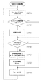
前述の動作により、画像データ処理装置2により距離値が取得されると(ST1)、画像処理回路46により、前のフレームにおける距離値が大きいか否かを判断し(ST2)、前のフレームにおける距離値より今回取得した距離値の方が大きい場合は、前のフレームにおける距離値に換えて今回取得した距離値を距離値用メモリ47に保存する(ST3)。前のフレームにおける距離値より今回取得した距離値の方が小さい場合は、距離値の置き換えは行わない。この動作を生成リフレッシュタイミングまで繰り返し行い、生成リフレッシュタイミングになったら(ST4)、距離値用メモリ47に保存された距離値に基づいて背景画像を生成する。その後、距離値用メモリ47に保存された距離値をリセットし(ST5)、次のフレームの距離値測定を行う(ST6)。
When the distance value is acquired by the image data processing device 2 by the above-described operation (ST1), the
次に、画像データ処理装置による距離値の補正動作について、図7に示すフローチャートを参照して説明する。 Next, the distance value correcting operation by the image data processing apparatus will be described with reference to the flowchart shown in FIG.
最初のリフレッシュタイミングとなるまでは(ST10:YES)、背景画像の基準点となる画素の距離値を取得し(ST11)、この基準点となる画素の距離値と、距離画像センサ1の設置位置から基準点までの測定距離との差を演算して、補正量を決定する(ST12)。そして、補正量に基づいて全画素の距離値を補正する(ST13)。その後、次のフレームの補正を行う(ST14)。 Until the first refresh timing is reached (ST10: YES), the distance value of the pixel that becomes the reference point of the background image is acquired (ST11), the distance value of the pixel that becomes the reference point, and the installation position of the distance image sensor 1 The correction amount is determined by calculating the difference from the measurement distance from the reference point to the reference point (ST12). Then, the distance values of all the pixels are corrected based on the correction amount (ST13). Thereafter, the next frame is corrected (ST14).
また、次の生成リフレッシュタイミングとなったら(ST15:YES)、前述の動作と同様に、背景画像の基準点となる画素の距離値を取得し(ST11)、基準点となる画素の距離値と、距離画像センサ1の設置位置から基準点までの測定距離との差を演算して補正量を決定し(ST12)、この補正量に基づいて全画素の距離値を補正する(ST13)。 When the next generation refresh timing is reached (ST15: YES), the distance value of the pixel serving as the reference point of the background image is acquired (ST11), and the distance value of the pixel serving as the reference point is obtained in the same manner as described above. The correction amount is determined by calculating the difference with the measurement distance from the installation position of the distance image sensor 1 to the reference point (ST12), and the distance values of all the pixels are corrected based on this correction amount (ST13).
以上述べたように、本実施形態においては、距離画像センサ1により取得された最大となる距離値を保存し、この距離値に基づいて背景画像を生成するようにしているので、距離画像センサ1の設置位置を変更した場合でも、容易に背景画像を生成することができる。また、離画像センサにより取得された基準となる画素の距離値と、あらかじめ測定しておいた距離画像センサ1の設置位置から基準点までの測定距離との差に基づいて、距離画像センサ1による全ての画素の距離値を補正するようにしているので、環境温度や経年変化により距離画像センサ1により測定された距離値が変動した場合でも、確実に絶対距離値に補正することができ、常に、正確な距離測定を行うことができる。 As described above, in the present embodiment, the maximum distance value acquired by the distance image sensor 1 is stored, and the background image is generated based on this distance value. Even when the installation position is changed, a background image can be easily generated. Further, based on the difference between the distance value of the reference pixel acquired by the remote image sensor and the measured distance from the installation position of the distance image sensor 1 to the reference point measured in advance, the distance image sensor 1 Since the distance values of all the pixels are corrected, even if the distance value measured by the distance image sensor 1 fluctuates due to the environmental temperature or secular change, it can be surely corrected to the absolute distance value. Accurate distance measurement can be performed.
なお、図8に示すように、距離画像センサ1により測定された最大となる距離値に対して距離画像センサ1側に近寄った距離の範囲である測距ゆらぎ範囲を設定し、距離画像センサ1により測定された距離値が、測距ゆらぎ範囲にある場合に、この距離値を用いないようにしてもよい。 As shown in FIG. 8, a distance measurement fluctuation range, which is a range of distances approaching the distance image sensor 1 with respect to the maximum distance value measured by the distance image sensor 1, is set. This distance value may not be used when the distance value measured by is in the distance measurement fluctuation range.
例えば、最大となる距離値を保存する際に、一度、何らかの異常により本来の距離よりも大きい距離値が測定された場合に、この距離値に基づいて背景画像を生成してしまうと、背景画像の精度が損なわれるおそれがある。しかしながら、このように、測距ゆらぎ範囲にある距離値を用いないようにすれば、本来の距離より大きく測定された異常な距離値を用いずに最大となる距離値を取得することができ、背景画像の精度を高めることができるものである。 For example, when storing a maximum distance value, if a distance value larger than the original distance is once measured due to some abnormality, if a background image is generated based on this distance value, the background image There is a possibility that the accuracy of the is impaired. However, in this way, if the distance value in the ranging fluctuation range is not used, the maximum distance value can be obtained without using the abnormal distance value measured larger than the original distance, The accuracy of the background image can be increased.
なお、本発明は前記実施形態に限定されるものではなく、本発明の趣旨に基づいて種々の変形が可能である。 In addition, this invention is not limited to the said embodiment, A various deformation | transformation is possible based on the meaning of this invention.
1 距離画像センサ
2 画像データ処理装置
3 出力装置
10 二次元スキャナ
11 固定部
13 第2可動部
15 第1可動部
20 制御部
21 レーザコントローラ
22 スキャナドライバ
24 レーザ投光部
25 レーザ素子
26 レーザドライバ
28 投光光学装置
29 発光モニタ
30 レーザ受光部
31 受光素子
32 受光光学装置
34 測距計測部
37 ストップタイミング生成回路
38 時間計測回路
39 距離値算出回路
46 画像処理回路
47 距離値用メモリ
DESCRIPTION OF SYMBOLS 1 Distance image sensor 2 Image data processor 3
Claims (5)
前記画像処理回路は、生成リフレッシュタイミングが来るまで前記距離画像センサにより繰り返し取得された各画素の距離値が最大となる距離値を保存しておき、前記生成リフレッシュタイミングになった際に各画素の最大の距離値に基づいて背景画像を生成することにより、次の生成リフレッシュタイミングが来るまでは前の生成リフレッシュタイミングで生成した背景画像を用いて距離画像を生成するように構成されている、距離画像処理システム。 A background image is generated based on the distance value of each pixel input from the distance image sensor for the scanning area, and a distance image is generated from the difference between the distance value of the background image and the newly acquired distance value. An image data processing device including an image processing circuit for performing,
The image processing circuit, by the distance image sensor to generate the refresh timing comes repeatedly advance distance values of the acquired pixels are is stored distance value having the maximum of each pixel when it becomes the generating refresh timing by generating the background image based on the maximum distance value, until arrival of the next generation refresh timing is configured to generate a distance image by using the background image generated by the generating refresh timing before the distance Image processing system.
Priority Applications (1)
| Application Number | Priority Date | Filing Date | Title |
|---|---|---|---|
| JP2009292547A JP5723096B2 (en) | 2009-12-24 | 2009-12-24 | Distance image processing system |
Applications Claiming Priority (1)
| Application Number | Priority Date | Filing Date | Title |
|---|---|---|---|
| JP2009292547A JP5723096B2 (en) | 2009-12-24 | 2009-12-24 | Distance image processing system |
Publications (2)
| Publication Number | Publication Date |
|---|---|
| JP2011133320A JP2011133320A (en) | 2011-07-07 |
| JP5723096B2 true JP5723096B2 (en) | 2015-05-27 |
Family
ID=44346220
Family Applications (1)
| Application Number | Title | Priority Date | Filing Date |
|---|---|---|---|
| JP2009292547A Active JP5723096B2 (en) | 2009-12-24 | 2009-12-24 | Distance image processing system |
Country Status (1)
| Country | Link |
|---|---|
| JP (1) | JP5723096B2 (en) |
Families Citing this family (4)
| Publication number | Priority date | Publication date | Assignee | Title |
|---|---|---|---|---|
| JP2014196963A (en) * | 2013-03-29 | 2014-10-16 | 日本信号株式会社 | Distance image processing system |
| WO2014208018A1 (en) * | 2013-06-26 | 2014-12-31 | パナソニックIpマネジメント株式会社 | Distance measuring system |
| JP6800681B2 (en) * | 2016-09-30 | 2020-12-16 | キヤノン株式会社 | Image processing equipment, image processing methods and computer programs |
| JP6895074B2 (en) * | 2017-08-30 | 2021-06-30 | コニカミノルタ株式会社 | Object detection system and object detection program |
Family Cites Families (6)
| Publication number | Priority date | Publication date | Assignee | Title |
|---|---|---|---|---|
| JP2000019253A (en) * | 1998-07-01 | 2000-01-21 | Nippon Signal Co Ltd:The | Obstacle detection device |
| JP4161910B2 (en) * | 2004-01-28 | 2008-10-08 | 株式会社デンソー | Distance image data generation device, generation method, and program |
| JP3941790B2 (en) * | 2004-04-08 | 2007-07-04 | 石川島播磨重工業株式会社 | Moving object detection apparatus and method |
| JP2006323651A (en) * | 2005-05-19 | 2006-11-30 | Atsumi Electric Co Ltd | Crime prevention sensor |
| JP4815190B2 (en) * | 2005-10-28 | 2011-11-16 | セコム株式会社 | Intrusion detection device |
| JP5065744B2 (en) * | 2007-04-20 | 2012-11-07 | パナソニック株式会社 | Individual detector |
-
2009
- 2009-12-24 JP JP2009292547A patent/JP5723096B2/en active Active
Also Published As
| Publication number | Publication date |
|---|---|
| JP2011133320A (en) | 2011-07-07 |
Similar Documents
| Publication | Publication Date | Title |
|---|---|---|
| US10792931B2 (en) | Optical deflection apparatus, head-up display apparatus, optical writing unit, image forming apparatus, and object recognition apparatus | |
| WO2009119229A1 (en) | Three-dimensional imaging device and method for calibrating three-dimensional imaging device | |
| JP5723096B2 (en) | Distance image processing system | |
| JP5710279B2 (en) | Optical distance measuring device | |
| US11115643B2 (en) | Alignment system | |
| JP5702923B2 (en) | Distance image processing system | |
| JP2022159464A (en) | Ranging device | |
| KR101299455B1 (en) | Light scanning unit, image forming apparatus having the same and sync calibration method of the light scanning unit | |
| JP6186863B2 (en) | Ranging device and program | |
| EP3199946B1 (en) | Deformation detecting device | |
| JP2005077288A (en) | Radar device | |
| JP2022097530A (en) | Methods for manufacturing ranging device and scanning device | |
| JP2014196963A (en) | Distance image processing system | |
| JP2014196962A (en) | Object detection system | |
| JP5688890B2 (en) | Distance image sensor and distance image processing system using the same | |
| JP2011004929A (en) | Endoscope apparatus | |
| JP2011004920A (en) | Endoscope apparatus | |
| JP6126433B2 (en) | Movable step monitoring system | |
| JP2017173258A (en) | Distance measurement device, distance measurement method, and program | |
| JP2009258089A (en) | Shape measuring apparatus | |
| JP3659239B2 (en) | Radar equipment | |
| JP2004157065A (en) | Radar device | |
| JP2010107575A (en) | Optical scanner | |
| KR20150005765A (en) | Method and apparatus for calibrating a laser marking system | |
| JP4420120B2 (en) | Adjusting method of imaging apparatus |
Legal Events
| Date | Code | Title | Description |
|---|---|---|---|
| A621 | Written request for application examination |
Free format text: JAPANESE INTERMEDIATE CODE: A621 Effective date: 20121217 |
|
| A977 | Report on retrieval |
Free format text: JAPANESE INTERMEDIATE CODE: A971007 Effective date: 20131010 |
|
| A131 | Notification of reasons for refusal |
Free format text: JAPANESE INTERMEDIATE CODE: A131 Effective date: 20131022 |
|
| A521 | Written amendment |
Free format text: JAPANESE INTERMEDIATE CODE: A523 Effective date: 20131224 |
|
| RD02 | Notification of acceptance of power of attorney |
Free format text: JAPANESE INTERMEDIATE CODE: A7422 Effective date: 20140121 |
|
| RD04 | Notification of resignation of power of attorney |
Free format text: JAPANESE INTERMEDIATE CODE: A7424 Effective date: 20140210 |
|
| A02 | Decision of refusal |
Free format text: JAPANESE INTERMEDIATE CODE: A02 Effective date: 20140909 |
|
| A521 | Written amendment |
Free format text: JAPANESE INTERMEDIATE CODE: A523 Effective date: 20141209 |
|
| A911 | Transfer of reconsideration by examiner before appeal (zenchi) |
Free format text: JAPANESE INTERMEDIATE CODE: A911 Effective date: 20141217 |
|
| TRDD | Decision of grant or rejection written | ||
| A01 | Written decision to grant a patent or to grant a registration (utility model) |
Free format text: JAPANESE INTERMEDIATE CODE: A01 Effective date: 20150303 |
|
| A61 | First payment of annual fees (during grant procedure) |
Free format text: JAPANESE INTERMEDIATE CODE: A61 Effective date: 20150327 |
|
| R150 | Certificate of patent or registration of utility model |
Ref document number: 5723096 Country of ref document: JP Free format text: JAPANESE INTERMEDIATE CODE: R150 |