JP5722224B2 - Handheld positioning interface for spatial query - Google Patents
Handheld positioning interface for spatial query Download PDFInfo
- Publication number
- JP5722224B2 JP5722224B2 JP2011533437A JP2011533437A JP5722224B2 JP 5722224 B2 JP5722224 B2 JP 5722224B2 JP 2011533437 A JP2011533437 A JP 2011533437A JP 2011533437 A JP2011533437 A JP 2011533437A JP 5722224 B2 JP5722224 B2 JP 5722224B2
- Authority
- JP
- Japan
- Prior art keywords
- orientation
- spatial position
- coordinate system
- relative
- handheld device
- Prior art date
- Legal status (The legal status is an assumption and is not a legal conclusion. Google has not performed a legal analysis and makes no representation as to the accuracy of the status listed.)
- Active
Links
- 238000000034 method Methods 0.000 claims description 49
- 230000033001 locomotion Effects 0.000 claims description 45
- 238000005259 measurement Methods 0.000 claims description 39
- 238000004891 communication Methods 0.000 claims description 17
- 230000009471 action Effects 0.000 claims description 6
- 230000003287 optical effect Effects 0.000 claims description 3
- 238000003384 imaging method Methods 0.000 claims description 2
- 239000013598 vector Substances 0.000 description 38
- 230000008569 process Effects 0.000 description 19
- 238000013519 translation Methods 0.000 description 13
- 238000010586 diagram Methods 0.000 description 10
- 239000011159 matrix material Substances 0.000 description 9
- 230000001133 acceleration Effects 0.000 description 6
- 230000004807 localization Effects 0.000 description 6
- 230000008859 change Effects 0.000 description 5
- 238000004364 calculation method Methods 0.000 description 4
- NJPPVKZQTLUDBO-UHFFFAOYSA-N novaluron Chemical group C1=C(Cl)C(OC(F)(F)C(OC(F)(F)F)F)=CC=C1NC(=O)NC(=O)C1=C(F)C=CC=C1F NJPPVKZQTLUDBO-UHFFFAOYSA-N 0.000 description 3
- 238000013459 approach Methods 0.000 description 2
- 230000008901 benefit Effects 0.000 description 2
- 238000009434 installation Methods 0.000 description 2
- 238000013507 mapping Methods 0.000 description 2
- 230000009466 transformation Effects 0.000 description 2
- 230000003213 activating effect Effects 0.000 description 1
- 239000004020 conductor Substances 0.000 description 1
- 238000010276 construction Methods 0.000 description 1
- 230000004069 differentiation Effects 0.000 description 1
- 238000006073 displacement reaction Methods 0.000 description 1
- 230000003203 everyday effect Effects 0.000 description 1
- 230000010354 integration Effects 0.000 description 1
- 230000003993 interaction Effects 0.000 description 1
- 238000012423 maintenance Methods 0.000 description 1
- 239000002184 metal Substances 0.000 description 1
- 238000003908 quality control method Methods 0.000 description 1
- 238000004088 simulation Methods 0.000 description 1
- 238000006467 substitution reaction Methods 0.000 description 1
- 230000000007 visual effect Effects 0.000 description 1
- 238000012800 visualization Methods 0.000 description 1
Images


Classifications
-
- G—PHYSICS
- G01—MEASURING; TESTING
- G01C—MEASURING DISTANCES, LEVELS OR BEARINGS; SURVEYING; NAVIGATION; GYROSCOPIC INSTRUMENTS; PHOTOGRAMMETRY OR VIDEOGRAMMETRY
- G01C15/00—Surveying instruments or accessories not provided for in groups G01C1/00 - G01C13/00
-
- G—PHYSICS
- G05—CONTROLLING; REGULATING
- G05B—CONTROL OR REGULATING SYSTEMS IN GENERAL; FUNCTIONAL ELEMENTS OF SUCH SYSTEMS; MONITORING OR TESTING ARRANGEMENTS FOR SUCH SYSTEMS OR ELEMENTS
- G05B19/00—Programme-control systems
- G05B19/02—Programme-control systems electric
- G05B19/04—Programme control other than numerical control, i.e. in sequence controllers or logic controllers
- G05B19/042—Programme control other than numerical control, i.e. in sequence controllers or logic controllers using digital processors
-
- G—PHYSICS
- G05—CONTROLLING; REGULATING
- G05B—CONTROL OR REGULATING SYSTEMS IN GENERAL; FUNCTIONAL ELEMENTS OF SUCH SYSTEMS; MONITORING OR TESTING ARRANGEMENTS FOR SUCH SYSTEMS OR ELEMENTS
- G05B2219/00—Program-control systems
- G05B2219/20—Pc systems
- G05B2219/23—Pc programming
- G05B2219/23406—Programmer device, portable, handheld detachable programmer
Landscapes
- Physics & Mathematics (AREA)
- Engineering & Computer Science (AREA)
- General Physics & Mathematics (AREA)
- Radar, Positioning & Navigation (AREA)
- Remote Sensing (AREA)
- Automation & Control Theory (AREA)
- Position Fixing By Use Of Radio Waves (AREA)
- Length Measuring Devices With Unspecified Measuring Means (AREA)
- Navigation (AREA)
Description
ここで説明する主題の実施形態は、一般に、既知の物体に対する手持ち型デバイスの位置および向きを求めるためのシステムおよび方法に関する。 Embodiments of the subject matter described herein generally relate to systems and methods for determining the position and orientation of a handheld device relative to a known object.
民間航空機のような大型かつ複雑なシステムとともに作業を行う際、機械工、技術者および検査官といった作業員は、これらシステムの現在位置における座標データおよび特定の部品に対する位置データにアクセスしなければならないことがよくある。いくつかの利用可能な位置決めシステムによると、器械が、その位置および向きを既知の物体に関連して求めることができる。これらシステムの多くは、多額の設備投資を要し、かつ、非常に大型であるので通常何らかの種類の接地支持物を要する。 When working with large and complex systems such as commercial aircraft, workers such as mechanics, technicians and inspectors must have access to coordinate data at the current location of these systems and position data for specific parts. Often there is. According to some available positioning systems, the instrument can determine its position and orientation relative to a known object. Many of these systems require significant capital investment and are usually very large and therefore usually require some sort of ground support.
商用のシステムには、ビデオカメラによるシステム、レーザによるシステム、GPSによるシステムおよびRFID三角測量によるシステムがある。ビデオカメラによるシステムには、複数カメラの位置および向き取り込みシステム、単一カメラの画素による画像システム、ならびに、単一カメラの位置および向きソフトウェアが含まれる。レーザによるシステムの例としては、干渉計によるシステム、電子距離測定レーザによるシステム、測量および建設用機器レーザシステムがある。GPSおよび差分GPSによるシステムは、軌道に乗って周回するGPS衛星から信号を受信するので、周回しているGPS衛星への視野方向が開けている屋外でもっともよく機能する。RFIDによるシステムは、作業領域の周囲に設置された複数の送信機から受信した信号に基づいて三角測量により位置を測定する。 Commercial systems include video camera systems, laser systems, GPS systems, and RFID triangulation systems. Video camera systems include multiple camera position and orientation capture systems, single camera pixel image systems, and single camera position and orientation software. Examples of laser systems include interferometer systems, electronic distance measurement laser systems, surveying and construction equipment laser systems. The system using GPS and differential GPS receives signals from orbiting GPS satellites, so it works best outdoors with a clear view direction to the orbiting GPS satellites. The RFID system measures the position by triangulation based on signals received from a plurality of transmitters installed around the work area.
ここで提示するのは、オフボードの追跡用構成部品の使用を必要とせずに、既知の物体に対するデバイスの位置および向きを求めるための低コストのシステムおよび方法である。さまざまな実施形態において、該システムおよび方法は、既知の物体の局所座標に対するデバイスの位置を求める位置指定プロセスとともに向きセンサを含むか、または、利用する。一実施形態において、一旦デバイスの初期位置が求まれば、該デバイス中の慣性測定ユニット(IMU)がデバイスの移動を追跡することにより、既知の物体の局所座標に対するデバイスの更新された位置を求める。別の実施形態において、該システムおよび方法は、3D仮想環境における運動に対する現実世界の運動の1:1マッピングを提供する。 Presented herein is a low cost system and method for determining the position and orientation of a device relative to a known object without requiring the use of off-board tracking components. In various embodiments, the systems and methods include or utilize an orientation sensor with a positioning process that determines the position of the device relative to the local coordinates of a known object. In one embodiment, once the initial position of the device is determined, an inertial measurement unit (IMU) in the device tracks the movement of the device to determine the updated position of the device relative to the local coordinates of a known object. . In another embodiment, the system and method provide a 1: 1 mapping of real world motion to motion in a 3D virtual environment.
一実施形態において、位置指定プロセスは、(a)手持ち型デバイスの初期位置を較正して、既知の物体に対する手持ち型デバイスの箇所を求め、(b)既知の物体に手持ち型デバイスの1本以上の軸の向きを合わせ、(c)手持ち型デバイス内のセンサを慣性測定ユニット(IMU)として用いて、手持ち型デバイスを既知の物体に関連して移動させながら、較正した初期位置と現在の位置との間の相対位置変化を測定することを含む。一実施形態において、手持ち型デバイスの現在の位置および向きを用いて、手持ち型デバイス上に既知の物体の一部、例えば、手持ち型デバイスが指示している既知の物体の一部についての関連情報を表示する。別の実施形態において、手持ち型デバイスは、手持ち型デバイスの現在の位置および向きを用いて、既知の物体の特定の箇所へユーザを導く。 In one embodiment, the location process includes (a) calibrating the initial position of the handheld device to determine the location of the handheld device relative to a known object, and (b) one or more of the handheld devices on the known object. (C) using the sensor in the handheld device as an inertial measurement unit (IMU) to move the handheld device relative to a known object while calibrating the initial and current positions Measuring the relative position change between. In one embodiment, using the current position and orientation of the handheld device, relevant information about the part of the known object on the handheld device, eg, the part of the known object that the handheld device is pointing to Is displayed. In another embodiment, the handheld device uses the current position and orientation of the handheld device to guide the user to a specific location on a known object.
一実施形態において、較正プロセスは、(a)既知の物体のある特徴または既知の物体上の既知の局所座標を有する複数の特徴に向けて手持ち型デバイスを指示し、(b)該特徴を指示しながら、手持ち型デバイスの向きを検知し、(c)既知の物体の追加の特徴に向けて手持ち型デバイスを指示し、該追加の特徴を指示しながら、手持ち型デバイスの向きを検知し、(d)センサの向きおよび特徴の局所座標を用いて計算を行って、既知の物体に対する手持ち型デバイスの初期位置を求めることを含む。別の実施形態において、手持ち型デバイス内のセンサは、較正プロセス中に相対位置平行移動および相対運動を測定する。別の実施形態において、向きセンサを用いて、既知の物体に対する手持ち型デバイスの向きを求める。 In one embodiment, the calibration process includes: (a) pointing a handheld device toward a feature of a known object or features having a known local coordinate on a known object; and (b) indicating the feature While detecting the orientation of the handheld device, (c) indicating the handheld device towards an additional feature of the known object, and detecting the orientation of the handheld device while indicating the additional feature; (D) performing a calculation using the sensor orientation and local coordinates of the feature to determine an initial position of the handheld device relative to a known object. In another embodiment, sensors in the handheld device measure relative position translation and relative movement during the calibration process. In another embodiment, an orientation sensor is used to determine the orientation of the handheld device relative to a known object.
取り上げられる特徴、機能および利点は、本発明のさまざまな実施形態において独立して達成可能であり、または、以下の説明および図面を参照してさらなる詳細が理解可能であるさらに他の実施形態において組み合わせてもよい。 The features, functions, and advantages addressed can be achieved independently in various embodiments of the invention or combined in yet other embodiments that can be understood in further detail with reference to the following description and drawings. May be.
添付の図は、空間照会のための手持ち型位置決めインタフェースのさまざまな実施形態を描写している。以下に各図を簡単に説明する。各図における同じ参照番号を有する要素は、同一のまたは機能的に類似の要素を示す。これに加えて、参照番号の左端の数字は、該参照番号が初めて現れる図面を示している。 The accompanying figures depict various embodiments of a handheld positioning interface for spatial query. Each figure is briefly described below. Elements having the same reference number in each figure indicate the same or functionally similar elements. In addition, the leftmost digit of the reference number indicates the drawing in which the reference number first appears.
以下の詳細な説明は、本質的に単なる例示に過ぎず、本発明の実施形態またはそのような実施形態の適用および使用を限定するよう意図されてはいない。さらに、請求項において、先行する技術分野、背景技術、発明の概要、図面の簡単な説明または以下の詳細な説明で提示されているいかなる明示または暗示された理論によっても束縛される意図はない。 The following detailed description is merely exemplary in nature and is not intended to limit the embodiments of the invention or the application and uses of such embodiments. Furthermore, there is no intention in the claims to be bound by any expressed or implied theory presented in the preceding technical field, background, brief summary of the invention, the brief description of the drawings or the following detailed description.
以下の説明は、ともに「接続されている」かまたは「結合されている」要素やノードや特徴に言及している。ここで用いられているように、特にはっきりそうでないと記載しない限り、「接続されている」とは、1つの要素、ノードまたは特徴が、必ずしも機械的にではなく、別の要素、ノードまたは特徴に直接結び付いて(または直接通じて)いるということを意味する。同様に、特にはっきりそうでないと記載しない限り、「結合されている」とは、1つの要素、ノードまたは特徴が、必ずしも機械的にではなく、別の要素/ノード/特徴に直接または間接的に結び付いて(または直接または間接的に通じて)いるということを意味する。同じように、特にはっきりそうでないと記載しない限り、「連通している」とは、1つの要素、ノードまたは特徴が、必ずしも機械的にではなく、別の要素/ノード/特徴に直接または間接的に結び付いて(または直接または間接的に通じて)いるということを意味する。したがって、図は、要素の1つの可能な配置構成を描写しているが、本開示の範囲を逸脱することなしに、描写されている主題の一実施形態において追加の介在する要素、デバイス、特徴または構成部品が存在していてもよい。 The following description refers to elements, nodes and features that are both “connected” or “coupled”. As used herein, unless stated otherwise, "connected" means that one element, node or feature is not necessarily mechanical, but another element, node or feature. Means directly connected to (or directly connected to). Similarly, unless specifically stated otherwise, “coupled” means that one element, node or feature is not necessarily mechanical, but directly or indirectly to another element / node / feature. It means that they are connected (or directly or indirectly). Similarly, unless stated otherwise, “in communication” means that one element, node or feature is not necessarily mechanical, but directly or indirectly to another element / node / feature. Means (or directly or indirectly). Thus, although the figure depicts one possible arrangement of elements, additional intervening elements, devices, features in one embodiment of the depicted subject matter without departing from the scope of the present disclosure Or a component may exist.
本開示で用いられているさまざまな技術用語を以下のように定義する。座標系は、直交する三方向(X、Y、Z)により規定された準拠座標系を指し、座標系は、移動している物体および静止している物体に付すことができる。デカルト座標は、直交(直角)座標系を指す。局所座標は、特定の物体に関連付けられた座標系を指す。方向ベクトルは、そのX、YおよびZ成分に基づいて説明された端部位置から原点位置への三次元測定値を指す。平行移動は、物体の向きを変えない直線または曲線運動を指す。回転は、物体を平行移動させることなく物体の向きを変える角運動を指す。位置は、特定の座標系において規定された点のX、YおよびZ測定値を特に指す。向きは、ある座標系の別の座標系に対する回転の測定値を特に指す。回転行列は、ある座標系の別の座標系に対する向きを記述する3×3直交行列を指す。変換行列は、ある座標系の別の座標系に対する相対位置および向きを記述する4×4同次行列を指す(時に、変換または行列と呼ばれる)。絶対運動は、世界座標系に対する移動を指す。相対運動は、ある座標系の別の座標系に対する移動を指す(時に、局所運動と呼ばれる)。ベクトル演算は、加算もしくは減算、または、ある座標系から別の座標系へ変換する回転行列を乗算することのできる同じ座標系において規定された方向ベクトルを指す。 Various technical terms used in the present disclosure are defined as follows. The coordinate system refers to a compliant coordinate system defined by three orthogonal directions (X, Y, Z), and the coordinate system can be attached to a moving object and a stationary object. Cartesian coordinates refer to an orthogonal (right angle) coordinate system. Local coordinates refer to the coordinate system associated with a particular object. The direction vector indicates a three-dimensional measurement value from the end position to the origin position described based on the X, Y, and Z components. Translation refers to linear or curvilinear motion that does not change the orientation of the object. Rotation refers to angular motion that changes the orientation of an object without translating the object. Position specifically refers to the X, Y and Z measurements of a point defined in a particular coordinate system. Orientation specifically refers to a measure of rotation of one coordinate system relative to another. A rotation matrix refers to a 3 × 3 orthogonal matrix that describes the orientation of one coordinate system relative to another. A transformation matrix refers to a 4 × 4 homogeneous matrix that describes the relative position and orientation of one coordinate system relative to another (sometimes called a transformation or matrix). Absolute motion refers to movement relative to the world coordinate system. Relative motion refers to the movement of one coordinate system relative to another (sometimes referred to as local motion). Vector operations refer to direction vectors defined in the same coordinate system that can be added or subtracted or multiplied by a rotation matrix that transforms from one coordinate system to another.
A.空間照会のための手持ち型位置決めデバイス
図1に示す空間照会のための手持ち型位置決めデバイスの一実施形態の模式図は、IMUによるデバイス100である。IMUによるデバイス100は、IMUによるデバイス100を把持するためのハンドル102と、ハンドル102上に位置するか、または、これと一体化された選択ボタン104と、ハンドル102の上端に結合された6軸慣性測定ユニット(6軸IMU106)と、6軸IMU106に結合されたレーザポインタ108とを含む。IMUによるデバイス100は、レーザポインタ108が対象物110の方向を指示するようにユーザ(図示せず)により保持されている。
A. Handheld Positioning Device for Spatial Query A schematic diagram of one embodiment of the handheld positioning device for spatial query shown in FIG. The IMU-based
動作において、ユーザは、IMUによるデバイス100を対象物110へ向けて指示し、選択ボタン104を作動させ、かつ、IMUによるデバイス100は、6軸IMU106の現在の状態を記録する。6軸IMU106は、全6DOF慣性航法システム(INS)用の検知構成部品を備えている。INSは、連続6自由度(DOF)測定が可能であり、該測定には、位置に対する3DOFおよび向きに対する3DOFが含まれている。6軸IMU106は、直線加速度の測定および角速度測定のためのそれぞれ加速度計およびジャイロを有する。次いで、時間測定とともに加速度計およびジャイロにより提供されるデータを数値積分して位置および向きデータとする。本実施形態ではレーザポインタ108である簡易な照準デバイスは、ユーザが、IMUによるデバイス100を対象物110上の所望の箇所へ向けて指示するのを助ける。代替の実施形態では、指示手段は、対象物110上の所望の箇所と目で見て位置合わせされた機械的手段、例えば、縁部などのIMUによるデバイス100自体の物理的特徴とすることも、投射光、レーザのような発光手段とすることも、IMUによるデバイス100に取り付けられたボアサイトのような光学手段とすることも、デジタルカメラにより指示された方向からの映像を示すための例えば付属のスクリーンまたはディスプレイを有するデジタルカメラとすることもできる。
In operation, the user directs the IMU-based
図2に例示する別の実施形態において、ジンバルによるデバイス200は、ジンバルによるデバイス200の角方位(angular orientation)の測定に用いられる。ジンバルによるデバイス200は、台座206に対するレーザポインタ108のチルト角度を測定するためのチルト角度センサ202と、台座206に対するレーザポインタ108のパン角度を測定するためのパン角度センサ204とを有する多軸ジンバル208を含む。合わせて、チルト角度センサ202およびパン角度センサ204は、ジンバルによるデバイス200のレーザポインタ108の角方位を高精度に測定することができる。これらチルト角度センサ202およびパン角度センサ204は、回転型エンコーダまたは回転型ポテンショメータを含んでいてもよいが、これに限定されない。回転型チルトおよびパン角度センサ202、204は、相対的角度を測定し、通常、ジャイロによる6軸IMU106より正確な角度測定が可能であるが、ジンバルによるデバイス200の潜在的欠点は、この特定の構成ではさらなる位置の平行移動に対応できないことである。というのも、初期位置からの相対的平行移動は、チルトおよびパン角度センサ202、204からだけでは測定できないからである。
In another embodiment illustrated in FIG. 2, the
図3に例示されている別の実施形態は、混成システム300である。混成システム300は、図1のIMUによるデバイス100における6軸IMU106と同様の3軸直線加速度計ユニット302と組み合わされた図2におけるジンバルによるデバイス200のジンバルによる向き測定構成部品を含む。混成システム300は、位置変化の測定を容易にしつつ、高精度角度測定を可能とする。
Another embodiment illustrated in FIG. 3 is a
図4に例示する別の実施形態は、適合通信デバイス400である。適合通信デバイス400は、無線または有線データ接続を有し、かつ、位置を求めるアプリケーションを実行するためのソフトウェアパッケージをロードした通信デバイス402を含む。ディスプレイスクリーン404は、ユーザインタフェースおよび選択トリガを提供する。通信デバイス402は、規定されたデバイス座標系406および慣性による測定センサ408が可能な携帯電話、PDA、または、類似の無線もしくは有線デバイスの形態を取ることができる。いくつかの現世代の携帯電話は、一体型汎用加速度計を有しており(たとえば、アップル(R)のiPhone(R))、未来のデバイスは、複数の自由度を有する慣性測定ユニット、すなわちIMUの検知構成部品を構成する角速度ジャイロをも含んでいてもよい。このことは、通信デバイス400に埋め込まれた慣性による測定センサ408として示されている。
Another embodiment illustrated in FIG. 4 is an adapted
他の実施形態では、その他の種類の加速度計―ジャイロユニットを通信デバイス400に外付けで結合してもよい。例えば、IMUによるデバイス100、ジンバルによるデバイス200または混成デバイス300は、通信デバイス400に通信可能に結合して、位置および向きを提供可能である。適正な数値積分ソフトウェアとともに、これら汎用MEMSによる加速度計および/またはジャイロスコープ構成部品は、位置および回転変化を測定する専用のIMUによるシステムと同様に機能する慣性航法システム(INS)用センサとして用いることができる。
In other embodiments, other types of accelerometer-gyro units may be externally coupled to the
通信デバイス400は、対象物110に照準を合わせるために用いられるレーザポインタ108とともに示されている。代替の実施形態では、照準スコープ、カメラ、ビデオカメラまたは通信デバイス400自体の物理的属性を、対象物110に照準を合わせるために用いることができる。これら代替の実施形態において、十字線または位置合わせマーク(図示せず)により、対象物110に対する正しい照準合わせを助けてもよい。
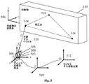
ここで図5を参照すると、手持ち型デバイス500の一実施形態は、IMU502と、簡易な照準デバイスとしてのレーザポインタ108とを含む。例示のみを目的として、対象物110として飛行機を用いてシステムおよび方法を説明するが、該システムおよび方法は、構造物、輸送手段、物体などのようなほとんどあらゆる対象物110に適用可能である。手持ち型デバイス500は、本実施例においては飛行機である対象物110の局所対象座標系506における手持ち型デバイス500の現在の位置および向きを求める。手持ち型デバイス500の厳密な位置および向きを知ることにより、ユーザは、飛行機の局所対象座標系506において保存されているデータベースから飛行機の部品および特徴についての情報を取り出すことができ、飛行機に対して施される構成、品質管理および維持の機能が促進される。この情報は、数値データ、CAD/3Dモデルおよび画像を含んでいてもよいが、これらに限定はされない。
Referring now to FIG. 5, one embodiment of a
さまざまな実施形態において、飛行機に関するこの情報は、手持ち型デバイス500上でユーザに対して表示される。例えば、ユーザに視認可能な部品とユーザの視界から遮られた、例えば、パネルの裏に隠れた部品との両方に関する情報を手持ち型デバイス500上に表示することができる。別の実施形態において、手持ち型デバイス500は、飛行機の局所座標系506における手持ち型デバイスの現在の位置および向きを求め、かつ、飛行機の所望の特徴、部品または位置の箇所にユーザを導くために手持ち型デバイス500上に命令を提示する。別の実施形態において、デバイス500により測定されたリアルタイムの位置および向きデータを用いて、仮想の物体を移動させるか、または、3D仮想環境またはCADアプリケーションにおける仮想視点を提供する。一実施形態では、これらのアプリケーションは、手持ち型デバイス500上で局所的に実行され、別の実施形態では、手持ち型デバイスは、手持ち型デバイス500と通信状態にあるコンピュータシステム(図示せず)に位置および向き情報を供給する。さらに別の実施形態では、手持ち型デバイス500からの位置および向きデータを用いて、例えば輸送手段である対象物110用診断システムへデータを伝えることにより、電圧、RPM、圧力、温度などといった診断システムの状態のリアルタイムフィードバックを表示できる。さらに別の実施形態において、デバイス500は、対象物110の内蔵システムと通信状態にある位置および向きデータを用いて、制御可能な構成部品を選択し、かつ、構成部品の調製可能なパラメータを設定する。
In various embodiments, this information about the airplane is displayed to the user on
B.設置および動作の概要
引き続き図5を参照して、位置指定プロセスは、対象物に対する手持ち型デバイス500の初期位置を求める。該位置指定プロセスは、手持ち型デバイス500を較正し、かつ、飛行機すなわち対象物110に対する手持ち型デバイス500の現在の箇所を見出す。本開示において用いられる手持ち型デバイス500局所化プロセスは、手持ち型デバイス500から対象物110上の既知の位置または較正点514、516、518への方向ベクトルVを求めることにかかっており、これら既知の位置または較正点は、手持ち型デバイス500の相対向きの測定値を用いることにより求められる。一旦このように較正されると、ユーザは次いで、手持ち型デバイス500を移動させ、IMU502は、較正位置508と追加の平行移動した位置510、512との間の相対位置変化を追跡する。本開示において後により詳細に説明する局所化プロセスは、対象物110と手持ち型デバイス500との間の相対位置ずれをもたらす。
B. Installation and Operation Overview With continued reference to FIG. 5, the location process determines the initial position of the
いくつかの実施形態において、対象物110に対する手持ち型デバイス500の向きは、使用中、例えば相対位置データしか必要でない場合は、要求されない。その他の実施形態において、手持ち型デバイス500はまた、対象物110に対する向きデータをも提供する。向きプロセスにより、対象物110に対して手持ち型デバイス500を位置合わせする。対象物110に対する手持ち型デバイス500の向きが必要なときは、いくつかの種々の方法で求めることができる。較正原点508からのわずかな移動が必要な状況に対しては、飛行機すなわち対象物110の軸に対して手持ち型デバイス500を視覚的に位置合わせすれば十分であるかもしれない。較正点508からさらに離間した位置に対するより正確な追跡が必要な場合は、ユーザは、飛行機すなわち対象物110(例えば床梁またはステンシル)上の何らかの既知の構造物またはマークに対して手持ち型デバイス500を位置合わせすることができる。相対向きをより多目的に求めるには、ベクトルによるアプローチを用いることができ、これもまた後に説明する。較正原位置508しか必要でない場合は、向き調整および平行移動を行う必要はない。
In some embodiments, the orientation of the
一旦、手持ち型デバイス500の開始位置508および向きが設定されると、ユーザが飛行機すなわち対象物110の中またはその周りを移動するにつれて、開始点508に対する手持ち型デバイス500のデカルト位置をリアルタイムで更新できる。全IMU502能力を有するシステムについては、位置ずれが、位置測定センサにより連続して測定され、初期位置508に追加される。このことは、図5における破線ならびにO’およびO’’が付されているさらなる特定点またはさらなる平行移動位置510、512により示されている。
Once the
C.初期位置較正プロセスの詳細
引き続き図5を参照して、初期位置較正プロセスは、IMU502の向きセンサ(例、図2および図3に示した3軸ジャイロまたはジンバルデバイス回転チルトおよびパン角度センサ202、204)を用いて、航空機110上の較正位置508から3つの既知の位置または3つの較正対象514、516、518への相対方向ベクトルを測定する。3つの較正対象514、516、518は、手持ち型デバイス500からの視線が開けているように、かつ、3つの較正対象514、516、518が同一線形順序に並ばないように選択される。一実施形態において、照準デバイスは、レーザポインタ108である。代替の実施形態では、簡易なボアサイトまたは望遠鏡のようなあらゆる視覚位置合わせ手段が使用できる。レーザポインタ108は、図1から図5に示されているように、IMU502に固定接続されており、その結果、レーザポインタ108およびIMU502は、ともに移動する。
C. Details of the Initial Position Calibration Process Continuing with reference to FIG. 5, the initial position calibration process includes an
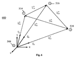
ここで図6を参照して、較正プロセス600は、3つのベクトルループ等式により定義された3つの連立一次方程式のシステムを解くことを含む。図6は、較正位置508となる手持ち型デバイス500(図示せず)の未知の箇所、および、対象物110上の3つの既知の較正点514、516、518の箇所を示している。本構成において、対象物110上のベクトルV12、V23およびV31は、単位ベクトルn1、n2およびn3と同様既知であり、単位ベクトルn1、n2およびn3の方向は、IMU502により測定されているが、これらベクトルの大きさ(d1、d2およびd3)は未知である。
Referring now to FIG. 6, the
解の微分は、等式1に示されている3つの固有ベクトルループ等式を定義することにより始まる。未知のベクトルV01、V02およびV03は、等式2に示されているように、未知の大きさd1、d2およびd3によるスカラ乗法により単位ベクトルn1、n2およびn3に関連付けられる。目標は、d1、d2およびd3を解くことであり、よって、V01、V02およびV03を見出すことである。

代入後は、等式3〜等式5に示されている3つの等式の3つの組となる。
これらの中で、各々から1つの等式を選択して、非特異な等式の組を作り、等式6に示すように行列の形:
![]()
に配置する。
![]()
To place.
Mを反転させ、両辺に予め掛けて、
![]()
とすることにより、列ベクトルAにおける未知数を解く。次いで、Aの値、すなわちd1、d2およびd3を等式2に代入すると、手持ち型デバイス500に対する対象物110の相対ずれが得られる。
Invert M and multiply both sides in advance.
![]()
To solve the unknown in the column vector A. Then, substituting the value of A, ie, d 1 , d 2, and d 3, into
この公式は、ジャイロによる角度測定デバイス(例えば、IMUによるデバイス100、混成デバイス300および適合通信デバイス400)とジンバルによるデバイス200との両方に適用される。また、手持ち型デバイス500の相対パン角度およびチルト角度しか計算には必要ない(すなわち、横揺れ角度は必要ない)ので、いくつかの実施形態では、IMU502は、パン角度およびチルト角度測定しか可能でない(すなわち、2自由度しか有さない)。
This formula applies to both gyro angle measurement devices (e.g.,
初期の方向ベクトルを測定する際、手持ち型デバイス500の位置の演算に用いられる方法は、3つの方向ベクトルの共通の交点を想定するが、デバイス500が手持ち型として意図されているので、3つのベクトルの原点は、共通の箇所で交差しない可能性がある。典型的な使用中は、ユーザの運動により小から中程度の位置ずれがあり、これにより局所位置演算に不正確さが生じるであろう。これらの運動を調整するためには、初期方向ベクトル取得時に3軸加速度計またはIMU502データを用いて、3つのベクトル原点O1、O2およびO3間の相対平行移動を測定することができる。
When measuring the initial direction vector, the method used to calculate the position of the
1つの選択肢は、方向ベクトル間の距離が最小となる点の平均箇所を見出すことにより、等価の回転中心を計算することである。次いで、較正演算の結果からこの相対ずれを減算する。これは近似解であることに注意されたい。 One option is to calculate the equivalent center of rotation by finding the average location of the points where the distance between the direction vectors is minimal. Next, the relative deviation is subtracted from the result of the calibration calculation. Note that this is an approximate solution.
より正確な解法は、3点較正法700であり、わずかに異なるシステム構成についてベクトルループ等式を解くことを含む。ここで図7を参照して、各ベクトルの原点O1、O2およびO3は異なった箇所にあるが、未知数の数は同じである。というのも、原点O1、O2およびO3は、(IMU502内の加速度計により測定されたデータから)既知の量だけずれているからである。等式において、このことにより等式6のBベクトルに含まれるさらなる既知の値が生じる。そこからは、解法プロセスは、原点O1、O2およびO3が交差するシステムに対する説明と同じである。
A more accurate solution is the three-
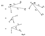
目標点ベクトルに沿った距離が直接測定されない3点較正法の別の実施形態において、初期相対位置決めプロセスにおいて求められた位置の解を用いた第2ステップにおいて向きを導出できる。この再構成された向きプロセス800に対して、相対位置を用いて、手持ち型デバイスにより測定された3つの単位ベクトルからの適正な長さの方向ベクトルを生成する。これにより、手持ち型デバイスの座標系において対象点を再構成でき、これら対象点は、図8のベクトル図においてPA1、PA2およびPA3が付されている。これから、以下に説明するプロセスを用いて座標系間の相対向きを求めることができる。
上の公式において、
![]()
は、点
![]()
から作られた座標系Aにおけるベクトルである(すなわち、
![]()
)。ベクトル
![]()
は、同じ形式に従う。
![]()
は、ベクトルの外積から作られた法線ベクトルであり、
![]()
は、回転軸であり、
θ1およびθ2は、それぞれ軸
![]()
の回りの回転角度であり、
R1、R2およびR3は、3×3対称回転行列であり、かつ、
f1()は、(2004年にPrentice Hallから出版されたJohn J. Craig著、"Introduction to Robotics; Mechanics and Control"、第3版に示されているように)以下に説明する角度軸定義から3×3回転行列を生成する関数である。
ここで、cθ=cos(θ)、sθ=sin(θ)、vθ=1−cos(θ)および
![]()
である。
In another embodiment of a three-point calibration method where the distance along the target point vector is not directly measured, the orientation can be derived in a second step using the position solution determined in the initial relative positioning process. For this
In the above formula,
![]()
Is a point
![]()
Is a vector in the coordinate system A made from (ie,
![]()
). vector
![]()
Follow the same format.
![]()
Is a normal vector made from the vector cross product,
![]()
Is the axis of rotation,
θ 1 and θ 2 are axes
![]()
Rotation angle around
R 1 , R 2 and R 3 are 3 × 3 symmetric rotation matrices, and
f 1 () is the angle axis definition described below (as shown in John J. Craig, published in 2004 by Prentice Hall, "Introduction to Robotics; Mechanics and Control", 3rd edition) Is a function that generates a 3 × 3 rotation matrix from
Where cθ = cos (θ), sθ = sin (θ), vθ = 1−cos (θ) and
![]()
It is.
D.演算
IMU502は、(3つのジャイロからの)角度変化率および(3つの加速度計からの)線形加速度を測定する。等式7および等式8に示すように、ジャイロからの生データを1回積分して角度を生成し、加速度計からのデータを2回積分して位置を生成する。
加速度データは、ジャイロデータから生成した回転行列を予め掛けることにより静止座標系に変換せねばならず、その後このタスクに用いることができる。また、データは、雑音軽減のためにフィルターをかけてもよい。6軸IMU106といったIMU502は、位置と向きとの両方においてドリフトしがちであり、これは、しばらくすると対象物に対する手持ち型デバイス500の再較正が必要であることを意味する。これらIMU502の問題は、この種の慣性航法システムに共通であり、本発明の開示に特有のものではないが、完全を期すためにここに含めた。その他の実施形態において、手持ち型デバイス500上で実行されるかまたはこれと通信状態にあるアプリケーションは、さらなる目的およびタスクのために加速度および/または速度データを用いる。
The acceleration data must be converted to a stationary coordinate system by pre-multiplying the rotation matrix generated from the gyro data and can then be used for this task. The data may also be filtered to reduce noise. An
2軸ジンバル208内の回転センサは、パン(θ1)およびチルト(θ2)角度において台座に対して単位を動かし、これは、等式9を用いることにより前に説明した方向ベクトルに変換可能である。
![]()
![]()
いくつかのアプリケーションについて、例えば手持ち型デバイス500のy軸または−z軸に沿った異なる方向において手持ち型デバイス500からレーザ光線を発出させることが有用かもしれない。これらの種類の実施形態において、該光線の方向は、新たな固定位置にレーザポインタ108を物理的に据え付けることにより、または、レーザポインタ108からのレーザ光線の経路に設置したビームスプリッタまたはミラーを用いることにより変えることができる。
For some applications, it may be useful to emit the laser beam from the
いくつかのアプリケーションにおいて、引き続き経路を記録しつつ、形状、例えば配線、管または縁部をたどることが有用かもしれない。そのような一実施形態では、ユーザが手持ち型デバイス500を移動させながら、ユーザが運動を簡単に制約して対象110に沿った経路をたどることができる既知の寸法の物理的導子(図示せず)(例えば、フック付き延長線)を手持ち型デバイス500に取り付ける。
In some applications, it may be useful to follow a shape, such as a wire, tube or edge, while continuing to record the path. In one such embodiment, a physical conductor of known dimensions (not shown) that allows the user to easily constrain movement and follow a path along the
ここで図9を参照して、システムの一実施形態は、局所化プロセス900と、ユーザインタフェース902と、箇所データを用いるアプリケーションと通信するインフラストラクチャ(例えば、3Dデータベースまたは視覚化サーバ)とを含む。このアプリケーションにおいて、ユーザは、空間データベース904から箇所特有の結果を抽出するために局所位置データが必要である。局所化サブシステム900は、3DOF向きセンサまたは6DOF慣性測定デバイス(例えば、IMU502)と、ポインティングデバイス(例えば、レーザポインタ108)と、位置計算ソフトウェア906とを含む。図10を参照して、ユーザアプリケーションインタフェース902の一実施形態を図示する。
Referring now to FIG. 9, one embodiment of a system includes a
E.利点および用途
手持ち型デバイス500は、IMU502を利用して位置を追跡し、これにより、GPSの受信が弱いまたは利用不可能な屋内またはその他の場所で手持ち型デバイス500を用いることができる。手持ち型デバイス500内のまたはこれに取り付けられたIMU502は、自立型であるので、位置決めシステムの使用前にまず追加のインフラストラクチャを所定場所、例えば、RFIDによる位置決めシステムを有効にするのに一般的に用いられる送受信機の周囲に設置する必要がなくなる。IMU502はまた、GPSまたはRFIDのいずれよりも高速に位置決めデータを提供することにより、移動のさらにより細かな粒度を考慮する。さらにIMU502は、低信号強度、信号休止、局所信号遮断、マルチパスエラーおよびその他の潜在的な信号経路の歪みといった、GPSおよびRFIDによるシステムで起こり得る送信機から受信機のエラーの可能性を解消する。信号経路の歪みは、飛行機において見られるような大量の金属の存在により予測困難かつ補償困難であり得る具合に悪化する可能性がある。IMU502は、失われたり歪んだりする可能性のある外部信号に依存していないので、位置正確性および信頼性を向上させる。さらに、手持ち型デバイス500は、この補助装置を必要としないので、概ねより安価に製造できる。
E. Benefits and
いくつかの実施形態において、手持ち型デバイス500は、手で持って、実施形態によっては片手で使用するのに十分な程度に小型かつ軽量なフォームファクタに構成されている。手持ち型デバイスは、一旦電源を入れるとすぐに使用可能である。簡易な較正手順により、現在の多くの商用位置決めシステムと比較してセットアップ時間が短くなる。この簡易かつ高速な較正により、機械工、技術者、検査官およびその他が、より複雑または高価な位置決めシステムの使用が妥当でない日常の用途で手持ち型デバイス500を用いることができる。
In some embodiments,
手持ち型デバイス500は、その使用のコストおよび容易さにより、あらゆる数の代替用途において用いることができる。例えば、手持ち型デバイス500を備えた旅行者は、ガイドの付かないツアーにおける博物館および史跡を見て回ることにより、その旅行者は、特定点を指示して、指示されている項目に関する関連情報を取り出すことができる。キャンパスや施設の訪問者は、手持ち型デバイス500を用いて、GPS信号が受信困難で、かつ、RFID送受信機の設置が非実用的である可能性のある屋内でも道案内を受けることができる。手持ち型デバイス500がアクセスするデータベースは、仮想物体、例えば組み立て中の飛行機を記述することができる。したがって、ビデオディスプレイと組んで手持ち型デバイス500を工場ツアーまたは見本市中に用いて、見込み客に仮想ツアーを提示することができる。
代替の実施形態において、手持ち型デバイス500は、対策を講じたり較正手順を実施したりすることなく、特定の位置に直接設置することができる。例えば、手持ち型デバイス500の位置および向きは、例えば前回のデバイスの較正からの対象物110の環境における固定インデックスマークを用いることにより、または既知の位置および向きを有する目印を用いることにより手動または自動的に入力することができる。これにより、ユーザは、手持ち型デバイス500を既知の箇所に返し、自ら(または他の誰か)が置いて行ったところで手に取ることができる。
In an alternative embodiment, the
別の実施形態において、手持ち型デバイス500への位置および向きの直接入力により、ユーザは、離れた箇所から対象物110との相互作用をシミュレートすることができる。このシミュレーションモードにおいて、さらなる運動制御法がある。これに加えて、物理的世界からCAD/3D仮想環境へのIMUの平行移動および回転の1:1マッピングの代わりに、手持ち型デバイス500は、手持ち型デバイス500の小さな運動が仮想環境における大きな運動を表すことができるよう運動を調節するよう構成されているか、または、手持ち型デバイス500の大きな運動を仮想環境における小さな運動に調節可能である。したがって、手持ち型デバイス500は、現実世界のものよりはるかに小さいか、はるかに大きいか、または、異なっている空間における仮想的移動に用いることができる。例えば、ディスプレイと組み合わせた手持ち型デバイス500により、教育者は、教室での講義中に手持ち型デバイス500を動かすことにより、既知の宇宙ほどの大きさのまたは原子ほどの小ささの何かの仮想ツアーに生徒を連れて行くことができる。本実施形態において、手持ち型デバイス500の位置は、物理的なコンピュータのマウスがマウスパッドの端に到達するとユーザがコンピュータのマウスを持ち上げて、位置を変えることにより、スクリーン上のカーソルを動かし続けるためのより大きなスペースを得るのと同等の方法でインデックス可能である。手持ち型デバイス500については、コンピュータのマウスでは標準である二次元だけではなく三から六次元でインデックスする。
In another embodiment, direct input of position and orientation to
一実施形態において、仮想環境における平行移動は、直接位置制御の代わりに、または、これに加えて速度制御を用いる。ここで図11を参照すると、デバイス1100は、まず初期位置1102に位置している。初期位置1102の第1半径1104内におけるデバイス1100のあらゆる移動が、直接位置決め運動を生じる。ユーザが、第1半径1104の内側へデバイス1100を戻すか、または、新たな初期位置(図示せず)にデバイス1100をインデックスし直すまで、第1半径1104の外側であるが第2半径1106の内側におけるデバイス1100のあらゆる移動が、初期位置1102から離間した方向への進行方向に沿った一定速度の連続運動をもたらす。第2半径1106の外側でデバイス1100を動かすことにより、ますます速い速度での当該方向における加速がもたらされる。
In one embodiment, translation in a virtual environment uses velocity control instead of or in addition to direct position control. Referring now to FIG. 11, the
別の実施形態において、仮想環境における向き変化は、平行移動について上に説明したものと類似の速度制御方法論を用いる。ここで図12を参照すると、デバイス1100の垂直軸(Z)1208が、初期の向き1202に対して内側扇状領域1204内で移動するとき、仮想環境における運動は、直接向き制御モードにある。デバイス1100の垂直軸1208が、さらに離間して初期の向き1202から外側扇状領域1206へと移動すると、速度制御法が有効となることにより、デバイス1100が静止状態に保持されていても、角度が引き続き増大する。運動を停止するには、ユーザは、初期の向き1202の近くの内側扇状領域1204へデバイス1100の垂直軸1208を戻すか、インデックスを適用する。
In another embodiment, orientation changes in the virtual environment use a speed control methodology similar to that described above for translation. Referring now to FIG. 12, when the vertical axis (Z) 1208 of the
速度制御の実施形態の両方において、平行移動または回転速度の測定である速度運動制御は、手持ち型デバイス1100により直接用いることもでき、他の使用のために離れた用途へ送ることもできる。同様に、加速度データは、手持ち型デバイス1100により直接用いることもでき、他の使用のために離れた用途へ送ることもできる。
In both velocity control embodiments, velocity motion control, which is a translation or rotational velocity measurement, can be used directly by the
図面に示し、かつ、上に説明した本発明のさまざまな実施形態は、添付の請求項の範囲内であってもよい数多くの実施形態の例示である。開示されたアプローチを利用して、既知の物体に対する手持ち型デバイスの位置および向きを求めることのできる手持ち型デバイスの数多くのその他の構成を作成してもよいと考えられている。当該特許から発行される特許範囲は、添付の請求項の範囲によってのみ限定されるというのが出願人の意図である。
また、本願は以下に記載する態様を含む。
(態様1)
既知の物体に対する空間位置を求めるための装置であって、
前記装置が特定点に向けられると選択表示を作動させるためのアクチュエータと、
前記選択表示が作動されると装置の向き表示を提供するための向き検出器と、
複数の前記向き表示を用いて既知の物体に対する装置の初期位置を較正するよう適合されたプロセッサと、
前記初期位置を示すための出力手段と
を含む装置。
(態様2)
機械的指示手段、発光手段、レーザ、光学手段およびデジタル撮像手段からなる群から選択される指示手段をさらに含む、態様1に記載のシステム。
(態様3)
前記向き検出器が、パン角度センサおよびチルト角度センサを有するジンバルと物理的に通じている指示手段である、態様1に記載のシステム。
(態様4)
装置の複数の位置移動表示を提供するための空間位置検出器をさらに含み、前記プロセッサが、前記複数の位置移動表示を用いて装置の現在の位置を追跡するようさらに適合されており、かつ、前記出力手段が前記現在の位置を示すよう適合されている、態様1に記載のシステム。
(態様5)
前記空間位置検出器が慣性測定ユニットを含む、態様4に記載のシステム。
(態様6)
前記慣性測定ユニットが、2自由度慣性測定ユニット、3自由度慣性測定ユニット、4自由度慣性測定ユニット、5自由度慣性測定ユニットおよび6自由度慣性測定ユニットからなる群から選択される、態様5に記載のシステム。
(態様7)
前記プロセッサが、複数の前記向き表示および前記複数の位置移動表示を用いて既知の物体に対する装置の初期位置を較正するよう適合されている、態様4に記載のシステム。
(態様8)
前記装置が自立型かつ手持ち型である態様1に記載のシステム。
(態様9)
前記装置が無線通信デバイスである態様1に記載のシステム。
(態様10)
特定点の空間位置を求める方法であって、
(a)既知の物体に対するデバイスの初期位置を求めるために前記デバイスを較正することであって、
(i)前記既知の物体の特徴に前記デバイスの照準手段を向けることであって、前記特徴が既知の箇所を有する、向けること、
(ii)前記向ける動作の間に前記デバイスの前記向きを検知すること、
(iii)複数の前記特徴に対して前記ステップ(i)および(ii)を繰り返すこと、ならびに、
(iv)前記既知の箇所および前記デバイス上の前記照準手段が向けられている前記複数の特徴に対する前記デバイスの前記向きを用いて、前記既知の物体に対する前記デバイスの前記初期位置を計算すること
をさらに含む、較正することと、
(b)新たな位置へ前記デバイスを移動させることと、
(c)前記デバイス内のセンサを用いて前記移動動作を検知することと、
(d)前記センサからの情報を用いて前記デバイスの前記新たな位置を計算することと、
(e)前記デバイスの前記新たな位置を出力することと
を含む方法。
(態様11)
ステップ(a)が、前記既知の物体に対する前記デバイスの初期の向きを求めることをさらに含み、ステップ(b)が、新たな向きに前記デバイスを向けることをさらに含み、ステップ(c)が、前記デバイス内の前記センサを用いて前記向ける動作を検知することをさらに含み、ステップ(d)が、前記センサからの情報を用いて前記デバイスの前記新たな向きを計算することをさらに含み、前記方法が、前記計算された初期位置、前記既知の箇所および前記デバイス上の前記照準手段が向けられている前記複数の特徴に対する前記デバイスの前記向きを用いて、前記既知の物体に対する前記デバイスの前記初期の向きを計算し、前記デバイスの前記新たな位置および前記新たな向きを出力するステップ(a)(v)をさらに含む、態様10に記載の方法。
(態様12)
ステップ(a)(v)が、前記既知の物体に前記デバイスの1本以上の軸の向きを合わせることを含む、態様11に記載の方法。
(態様13)
前記既知の物体の前記座標系が前記デバイスの座標系とは異なる、態様10に記載の方法。
(態様14)
前記ステップ(a)(ii)が、向ける動作のたびに、前回の向ける動作と現在の向ける動作との間の前記デバイスの移動を検知することをさらに含み、かつ、前記ステップ(a)(iv)が、前記既知の箇所、前記デバイス上の前記照準手段が向けられている前記複数の特徴に対する前記デバイスの前記向き、および前記向ける動作間の前記デバイスの前記移動を用いて、前記既知の物体に対する前記デバイスの前記初期位置を計算する、態様10に記載の方法。
(態様15)
前記デバイスの前記新たな位置および新たな向きに少なくとも部分的に基づいて前記既知の物体に関する情報を表示することをさらに含み、前記情報が、前記既知の物体の座標系における前記デバイスの前記新たな位置を用いて取り出される、態様11に記載の方法。
The various embodiments of the invention shown in the drawings and described above are illustrative of numerous embodiments that may be within the scope of the appended claims. It is contemplated that the disclosed approach may be utilized to create many other configurations of handheld devices that can determine the position and orientation of the handheld device relative to a known object. It is the applicant's intention that the patent scope issued from this patent is limited only by the scope of the appended claims.
Moreover, this application contains the aspect described below.
(Aspect 1)
An apparatus for determining a spatial position with respect to a known object,
An actuator for activating a selection display when the device is pointed to a specific point;
An orientation detector for providing an orientation indication of the device when the selection indication is activated;
A processor adapted to calibrate the initial position of the device relative to a known object using a plurality of said orientation indications;
Output means for indicating the initial position;
Including the device.
(Aspect 2)
The system according to
(Aspect 3)
A system according to
(Aspect 4)
A spatial position detector for providing a plurality of position movement indications of the device, wherein the processor is further adapted to track the current position of the device using the plurality of position movement indications; and A system according to
(Aspect 5)
A system according to aspect 4, wherein the spatial position detector comprises an inertial measurement unit.
(Aspect 6)
Aspect 5 wherein the inertial measurement unit is selected from the group consisting of a 2-DOF inertial measurement unit, a 3-DOF inertial measurement unit, a 4-DOF inertial measurement unit, a 5-DOF inertial measurement unit, and a 6-DOF inertial measurement unit. The system described in.
(Aspect 7)
5. The system of aspect 4, wherein the processor is adapted to calibrate an initial position of the device relative to a known object using a plurality of the orientation indications and the plurality of position movement indications.
(Aspect 8)
The system according to
(Aspect 9)
The system according to
(Aspect 10)
A method for obtaining a spatial position of a specific point,
(A) calibrating the device to determine the initial position of the device relative to a known object,
(I) directing the aiming means of the device to a feature of the known object, wherein the feature has a known location;
(Ii) detecting the orientation of the device during the turning action;
(Iii) repeating the steps (i) and (ii) for a plurality of the features; and
(Iv) calculating the initial position of the device relative to the known object using the known location and the orientation of the device relative to the plurality of features to which the aiming means on the device is directed;
Calibrating, further comprising:
(B) moving the device to a new location;
(C) detecting the movement using a sensor in the device;
(D) calculating the new position of the device using information from the sensor;
(E) outputting the new position of the device;
Including methods.
(Aspect 11)
Step (a) further comprises determining an initial orientation of the device relative to the known object, step (b) further comprises directing the device in a new orientation, and step (c) comprises the step Further comprising detecting the directing motion using the sensor in the device, and step (d) further comprises calculating the new orientation of the device using information from the sensor; The initial position of the device relative to the known object using the calculated initial position, the known location and the orientation of the device relative to the plurality of features to which the aiming means on the device is directed. Further comprising: (a) (v) calculating the orientation of the device and outputting the new position and the new orientation of the device The method according to.
(Aspect 12)
12. A method according to aspect 11, wherein steps (a) and (v) comprise orienting one or more axes of the device to the known object.
(Aspect 13)
The method of aspect 10, wherein the coordinate system of the known object is different from the coordinate system of the device.
(Aspect 14)
The step (a) (ii) further includes detecting movement of the device between a previous pointing action and a current pointing action for each pointing action, and the step (a) (iv) ) Using the known location, the orientation of the device relative to the plurality of features to which the aiming means on the device is directed, and the movement of the device during the aiming movement The method of claim 10, wherein the initial position of the device relative to is calculated.
(Aspect 15)
Further comprising displaying information about the known object based at least in part on the new position and new orientation of the device, wherein the information is the new position of the device in the coordinate system of the known object. The method of embodiment 11, wherein the method is removed using the location.
Claims (8)
前記装置が特定点に向けられると、前記装置の向きを提供するための向き検出器と、
前記装置の複数の位置移動量を提供するための慣性測定ユニットを含む空間位置検出器と、
前記既知の局所座標系に対する前記装置の初期空間位置を較正し、前記複数の位置移動量を用いて前記装置の現在の空間位置を追跡するよう適合されたプロセッサと、
前記空間位置を示すための出力手段と、
を含み、
前記プロセッサが、前記既知の物体上にあって同一線形順序に並ばない3つの特定点の座標、前記装置が当該特定点に向けられた時の3つの前記向き、および、前回前記装置が特定点に向けられた時と現在前記装置が特定点に向けられた時との間の前記装置の位置移動量を用いて、前記既知の局所座標系に対する前記装置の初期空間位置を較正するようさらに適合されており、かつ、
前記出力手段が前記現在の空間位置を示すよう適合されている、
装置。 An apparatus for determining a spatial position with respect to a known local coordinate system possessed by a known object ,
When the device is directed to a particular point, and orientation detector for providing an orientation of said device,
A spatial position detector including an inertial measurement unit for providing a plurality of position shifts of the apparatus;
A processor adapted to calibrate the initial spatial position of the device relative to the known local coordinate system and track the current spatial position of the device using the plurality of position movements ;
Output means for indicating the spatial position ;
Including
Before Symbol processor, the coordinates of the known not aligned in the same linear order be on an object three specific points, the device has three of said facing when directed to the specific point, and, last the device specific Using the amount of movement of the device between when it is pointed to and when the device is currently pointed at a specific point, to further calibrate the initial spatial position of the device with respect to the known local coordinate system Is adapted, and
The output means is adapted to indicate the current spatial position;
Equipment .
ステップ(a)前記既知の局所座標系に対する前記デバイスの初期空間位置を求めるために前記デバイスを較正することであって、
(i)前記既知の物体の特徴に前記デバイスの照準手段を向けることであって、前記特徴が既知のロケーションを有する、向けること、
(ii)前記照準手段が向けられている複数の前記特徴に対する前記デバイスの向きを検知し、向ける動作のたびに、前回の向ける動作と現在の向ける動作との間の前記デバイスの移動量を検知すること、
(iii)複数の前記特徴に対して前記(i)および(ii)を繰り返すこと、ならびに、
(iv)前記既知のロケーション、前記照準手段が向けられている複数の前記特徴に対する前記デバイスの前記向き、および前記向ける動作間の前記デバイスの移動量を用いて、前記既知の局所座標系に対する前記デバイスの前記初期空間位置を計算すること
を含む、較正することと、
ステップ(b)新たな空間位置へ前記デバイスを移動させることと、
ステップ(c)前記デバイス内のセンサを慣性測定ユニットとして用いて前記デバイスの移動量を検知することと、
ステップ(d)前記センサからの情報を用いて前記デバイスの前記新たな空間位置を計算することと、
ステップ(e)前記デバイスの前記新たな空間位置を出力することと、
を含む方法。 A method for determining a spatial position of a device with respect to a known local coordinate system possessed by a known object ,
Step (a) calibrating the device to determine an initial spatial position of the device relative to the known local coordinate system ,
(I) directing the aiming means of the device to a feature of the known object, wherein the feature has a known location;
(Ii) detecting the come direction of the device relative to the plurality of the feature that has been directed the aiming means, every time the motion of turning, the moving amount of the device between the operation and the current directing motion of turning the last Detecting ,
(Iii) repeating ( i) and (ii) for a plurality of the features, and
(Iv) using the known location, the orientation of the device with respect to the plurality of features to which the aiming means is directed , and the amount of movement of the device between the directed movements, with respect to the known local coordinate system; Calibrating, including calculating the initial spatial position of the device;
Step (b) moving the device to a new spatial position;
Step (c) detecting the amount of movement of the device using a sensor in the device as an inertial measurement unit;
Step (d) calculating the new spatial position of the device using information from the sensor;
Step (e) outputting the new spatial position of the device;
Including methods.
前記方法が、前記計算された初期空間位置、前記既知のロケーションおよび前記デバイス上の前記照準手段が向けられている前記複数の特徴に対する前記デバイスの前記向きを用いて、前記既知の局所座標系に対する前記デバイスの前記初期の向きを計算するステップ(a)(v)をさらに含む、請求項5に記載の方法。 Step (a) further comprises determining an initial orientation of the device relative to the known local coordinate system ;
Before SL method, the calculated initial spatial position, with the orientation of the device relative to the plurality of features has been directed the aiming means on said known location and said device, the known local coordinate system 6. The method of claim 5, further comprising the steps (a) (v) of calculating the initial orientation of the device relative to .
ステップ(c)が、前記デバイス内の前記センサを用いて前記向ける動作を検知することをさらに含み、Step (c) further comprises detecting the directing action using the sensor in the device;
ステップ(d)が、前記センサからの情報を用いて前記デバイスの前記新たな向きを計算することをさらに含む、請求項5に記載の方法。The method of claim 5, wherein step (d) further comprises calculating the new orientation of the device using information from the sensor.
Applications Claiming Priority (3)
| Application Number | Priority Date | Filing Date | Title |
|---|---|---|---|
| US12/259,947 | 2008-10-28 | ||
| US12/259,947 US8138938B2 (en) | 2008-10-28 | 2008-10-28 | Hand-held positioning interface for spatial query |
| PCT/US2009/062441 WO2010053809A1 (en) | 2008-10-28 | 2009-10-28 | Hand-held positioning interface for spatial query |
Publications (3)
| Publication Number | Publication Date |
|---|---|
| JP2012507011A JP2012507011A (en) | 2012-03-22 |
| JP2012507011A5 JP2012507011A5 (en) | 2012-10-04 |
| JP5722224B2 true JP5722224B2 (en) | 2015-05-20 |
Family
ID=41665019
Family Applications (1)
| Application Number | Title | Priority Date | Filing Date |
|---|---|---|---|
| JP2011533437A Active JP5722224B2 (en) | 2008-10-28 | 2009-10-28 | Handheld positioning interface for spatial query |
Country Status (4)
| Country | Link |
|---|---|
| US (1) | US8138938B2 (en) |
| EP (1) | EP2350562B1 (en) |
| JP (1) | JP5722224B2 (en) |
| WO (1) | WO2010053809A1 (en) |
Families Citing this family (66)
| Publication number | Priority date | Publication date | Assignee | Title |
|---|---|---|---|---|
| US7958644B2 (en) * | 2006-06-23 | 2011-06-14 | Nxp B.V. | Orientation sensing in a multi part device |
| US9423250B1 (en) | 2009-12-17 | 2016-08-23 | The Boeing Company | Position measurement correction using loop-closure and movement data |
| US8279412B2 (en) * | 2009-12-17 | 2012-10-02 | The Boeing Company | Position and orientation determination using movement data |
| US9149929B2 (en) | 2010-05-26 | 2015-10-06 | The Boeing Company | Methods and systems for inspection sensor placement |
| US20120120230A1 (en) * | 2010-11-17 | 2012-05-17 | Utah State University | Apparatus and Method for Small Scale Wind Mapping |
| FR2972012B1 (en) * | 2011-02-25 | 2013-03-15 | Commissariat Energie Atomique | METHOD FOR ASSISTING THE PLACEMENT OF CONSTRUCTION ELEMENTS OF A CIVIL ENGINEERING WORK |
| US8447805B2 (en) | 2011-02-28 | 2013-05-21 | The Boeing Company | Distributed operation of a local positioning system |
| JP5670798B2 (en) * | 2011-03-30 | 2015-02-18 | フェリカネットワークス株式会社 | Communication terminal, communication method, and program |
| US8407111B2 (en) * | 2011-03-31 | 2013-03-26 | General Electric Company | Method, system and computer program product for correlating information and location |
| US9273990B1 (en) * | 2011-09-11 | 2016-03-01 | The Boeing Company | Aircraft repair fixture |
| US8768560B2 (en) * | 2011-10-04 | 2014-07-01 | Webtech Wireless Inc. | Method and system for performing calibration of an accelerometer of a telematics device during installation in a vehicle |
| US8556162B2 (en) * | 2011-11-21 | 2013-10-15 | The Boeing Company | Component programming system |
| US10268761B2 (en) | 2011-12-21 | 2019-04-23 | The Boeing Company | Panoptic visualization document collection |
| US9524342B2 (en) | 2011-12-21 | 2016-12-20 | The Boeing Company | Panoptic visualization document navigation |
| US9104760B2 (en) | 2011-12-21 | 2015-08-11 | The Boeing Company | Panoptic visualization document database management |
| US20130238511A1 (en) * | 2012-03-08 | 2013-09-12 | Airbus Operations Sas | System and method for end-of-life processing of an airframe |
| US9495476B2 (en) | 2012-03-23 | 2016-11-15 | The Boeing Company | Panoptic visualization of an illustrated parts catalog |
| US9058681B2 (en) | 2012-06-01 | 2015-06-16 | The Boeing Company | Sensor-enhanced localization in virtual and physical environments |
| US10380469B2 (en) * | 2012-07-18 | 2019-08-13 | The Boeing Company | Method for tracking a device in a landmark-based reference system |
| US10268662B2 (en) | 2012-09-10 | 2019-04-23 | The Boeing Company | Panoptic visualization of a document according to the structure thereof |
| US10275428B2 (en) | 2012-09-25 | 2019-04-30 | The Boeing Company | Panoptic visualization document differencing |
| DE102012217282B4 (en) * | 2012-09-25 | 2023-03-02 | Trimble Jena Gmbh | Method and device for assigning measuring points to a set of fixed points |
| US10824680B2 (en) | 2012-10-02 | 2020-11-03 | The Boeing Company | Panoptic visualization document access control |
| KR101416364B1 (en) | 2012-10-15 | 2014-07-08 | 현대자동차 주식회사 | Pointing navigation device and the method, pointing navigation system for a personal mobility using the same |
| US9875220B2 (en) | 2012-11-09 | 2018-01-23 | The Boeing Company | Panoptic visualization document printing |
| US9734625B2 (en) | 2013-01-28 | 2017-08-15 | The Boeing Company | Panoptic visualization of a three-dimensional representation of a complex system |
| US9665557B2 (en) | 2013-01-28 | 2017-05-30 | The Boeing Company | Panoptic visualization of elements of a complex system using localization of a point on a physical instance of the complex system |
| US9858245B2 (en) | 2013-01-28 | 2018-01-02 | The Boeing Company | Panoptic visualization of elements of a complex system using a model viewer |
| US9098593B2 (en) | 2013-04-23 | 2015-08-04 | The Boeing Company | Barcode access to electronic resources for lifecycle tracking of complex system parts |
| US8887993B2 (en) | 2013-04-23 | 2014-11-18 | The Boeing Company | Barcode access to electronic resources for complex system parts |
| FR3005819B1 (en) * | 2013-05-15 | 2015-05-01 | Thales Sa | MAINTENANCE SUPPORT DEVICE AND MAINTENANCE METHOD USING SUCH A DEVICE |
| US9430822B2 (en) | 2013-06-14 | 2016-08-30 | Microsoft Technology Licensing, Llc | Mobile imaging platform calibration |
| JP6320000B2 (en) * | 2013-11-22 | 2018-05-09 | 株式会社日立システムズ | Spatial coordinate measurement method, spatial coordinate measurement system, spatial coordinate measurement program, and laser pointer |
| US9355498B2 (en) | 2014-06-19 | 2016-05-31 | The Boeing Company | Viewpoint control of a display of a virtual product in a virtual environment |
| US10191997B2 (en) | 2014-08-21 | 2019-01-29 | The Boeing Company | Visualization and diagnostic analysis of interested elements of a complex system |
| US9841870B2 (en) | 2014-08-21 | 2017-12-12 | The Boeing Company | Integrated visualization and analysis of a complex system |
| US9489597B2 (en) | 2014-08-21 | 2016-11-08 | The Boeing Company | Visualization and analysis of a topical element of a complex system |
| JP6193195B2 (en) | 2014-09-17 | 2017-09-06 | 株式会社東芝 | Movement support apparatus, method and program |
| US20190117128A1 (en) * | 2015-03-19 | 2019-04-25 | Meloq Ab | Method and device for anatomical angle measurement |
| US9924103B2 (en) * | 2015-04-09 | 2018-03-20 | The Boeing Company | Automated local positioning system calibration using optically readable markers |
| FR3043815A1 (en) * | 2015-11-13 | 2017-05-19 | Airbus Operations Sas | METHOD FOR DISPLAYING IMAGES CORRESPONDING TO AN OUTER ENVIRONMENT OF THE VEHICLE ON A MOBILE DISPLAY DEVICE EMBEDDED IN A VEHICLE |
| US9892558B2 (en) * | 2016-02-19 | 2018-02-13 | The Boeing Company | Methods for localization using geotagged photographs and three-dimensional visualization |
| US10989542B2 (en) | 2016-03-11 | 2021-04-27 | Kaarta, Inc. | Aligning measured signal data with slam localization data and uses thereof |
| WO2017155970A1 (en) | 2016-03-11 | 2017-09-14 | Kaarta, Inc. | Laser scanner with real-time, online ego-motion estimation |
| US11573325B2 (en) | 2016-03-11 | 2023-02-07 | Kaarta, Inc. | Systems and methods for improvements in scanning and mapping |
| US11567201B2 (en) | 2016-03-11 | 2023-01-31 | Kaarta, Inc. | Laser scanner with real-time, online ego-motion estimation |
| US10155596B2 (en) | 2016-06-06 | 2018-12-18 | The Boeing Company | Three-dimensional aircraft inspection system for layout of passenger accommodations |
| US10274924B2 (en) | 2016-06-30 | 2019-04-30 | Sharp Laboratories Of America, Inc. | System and method for docking an actively stabilized platform |
| CN109923852B (en) * | 2017-01-24 | 2021-09-17 | 深圳市大疆灵眸科技有限公司 | Method, system, and medium for query response by camera mounted on pan/tilt head |
| EP4414951A2 (en) | 2017-04-27 | 2024-08-14 | Magic Leap, Inc. | Light-emitting user input device |
| US10627475B2 (en) * | 2017-05-05 | 2020-04-21 | The Boeing Company | Pose estimation using radio frequency identification (RFID) tags |
| DE102017213555A1 (en) | 2017-08-04 | 2019-02-07 | Siemens Aktiengesellschaft | An apparatus and method for location-based location of a location on a surface of an object |
| JP7018286B2 (en) * | 2017-10-04 | 2022-02-10 | Ihi運搬機械株式会社 | Crane suspension member guidance system |
| WO2019099605A1 (en) | 2017-11-17 | 2019-05-23 | Kaarta, Inc. | Methods and systems for geo-referencing mapping systems |
| CN110313177B (en) * | 2018-01-31 | 2021-09-28 | 深圳市大疆创新科技有限公司 | Holder control method and device |
| WO2019165194A1 (en) | 2018-02-23 | 2019-08-29 | Kaarta, Inc. | Methods and systems for processing and colorizing point clouds and meshes |
| KR102122600B1 (en) | 2018-03-07 | 2020-06-12 | 매직 립, 인코포레이티드 | Visual tracking of peripheral devices |
| WO2019195270A1 (en) | 2018-04-03 | 2019-10-10 | Kaarta, Inc. | Methods and systems for real or near real-time point cloud map data confidence evaluation |
| WO2019236588A1 (en) | 2018-06-04 | 2019-12-12 | The Research Foundation For The State University Of New York | System and method associated with expedient determination of location of one or more object(s) within a bounded perimeter of 3d space based on mapping and navigation to a precise poi destination using a smart laser pointer device |
| US11094221B2 (en) * | 2018-06-21 | 2021-08-17 | University Of Utah Research Foundation | Visual guidance system and method for posing a physical object in three dimensional space |
| US10800550B2 (en) | 2018-06-21 | 2020-10-13 | The Boeing Company | Positioning enhancements to localization process for three-dimensional visualization |
| WO2020009826A1 (en) | 2018-07-05 | 2020-01-09 | Kaarta, Inc. | Methods and systems for auto-leveling of point clouds and 3d models |
| EP3623996A1 (en) * | 2018-09-12 | 2020-03-18 | Aptiv Technologies Limited | Method for determining a coordinate of a feature point of an object in a 3d space |
| CN109461295B (en) * | 2018-12-07 | 2021-06-11 | 连尚(新昌)网络科技有限公司 | Household alarm method and equipment |
| US11029369B1 (en) * | 2019-01-26 | 2021-06-08 | Alken Inc. | Self-leveling magnetic source |
| US10929670B1 (en) | 2019-10-21 | 2021-02-23 | The Boeing Company | Marker-to-model location pairing and registration for augmented reality applications |
Family Cites Families (20)
| Publication number | Priority date | Publication date | Assignee | Title |
|---|---|---|---|---|
| JPS5942410A (en) * | 1982-09-02 | 1984-03-09 | Nec Corp | Self-position calculating method |
| US4806936A (en) * | 1986-06-20 | 1989-02-21 | Hughes Aircraft Company | Method of determining the position of multiple targets using bearing-only sensors |
| US5150310A (en) * | 1989-08-30 | 1992-09-22 | Consolve, Inc. | Method and apparatus for position detection |
| JP3274290B2 (en) * | 1994-09-19 | 2002-04-15 | 三菱電機株式会社 | Video display device and video display system |
| JPH10274526A (en) * | 1997-03-31 | 1998-10-13 | Taisei Corp | Position coordinate detection device and surveying device therewith |
| FR2770317B1 (en) * | 1997-10-24 | 2000-12-08 | Commissariat Energie Atomique | METHOD FOR CALIBRATING THE ORIGINAL POSITION AND ORIENTATION OF ONE OR MORE MOBILE CAMERAS AND ITS APPLICATION TO MEASURING THE THREE-DIMENSIONAL POSITION OF FIXED OBJECTS |
| US6671058B1 (en) * | 1998-03-23 | 2003-12-30 | Leica Geosystems Ag | Method for determining the position and rotational position of an object |
| GB2353659A (en) | 1998-05-15 | 2001-02-28 | Tricorder Technology Plc | Method and apparatus for 3D representation |
| BE1014137A6 (en) * | 2001-04-24 | 2003-05-06 | Krypton Electronic Eng Nv | Method and device for verification and identification of a measuring device. |
| EP1447644A1 (en) * | 2003-02-14 | 2004-08-18 | Metronor ASA | Measurement of spatial coordinates |
| JP4002211B2 (en) * | 2003-05-23 | 2007-10-31 | 三菱電機株式会社 | Field work support device |
| GB2413314B (en) * | 2003-09-02 | 2006-07-26 | Komatsu Mfg Co Ltd | Construction target indicator device |
| DE10359415A1 (en) | 2003-12-16 | 2005-07-14 | Trimble Jena Gmbh | Method for calibrating a surveying device |
| JP2005326275A (en) | 2004-05-14 | 2005-11-24 | Canon Inc | Information processing method and device |
| JP2006155195A (en) * | 2004-11-29 | 2006-06-15 | Yaskawa Electric Corp | Self-position identification device of mobile body and self-position identification method of mobile body |
| EP1669776A1 (en) * | 2004-12-11 | 2006-06-14 | Leica Geosystems AG | Handheld distance measuring apparatus and a method therefore |
| JP2008261755A (en) | 2007-04-12 | 2008-10-30 | Canon Inc | Information processing apparatus and information processing method |
| US8044991B2 (en) * | 2007-09-28 | 2011-10-25 | The Boeing Company | Local positioning system and method |
| US7859655B2 (en) * | 2007-09-28 | 2010-12-28 | The Boeing Company | Method involving a pointing instrument and a target object |
| US20100225498A1 (en) * | 2009-03-05 | 2010-09-09 | Searete Llc, A Limited Liability Corporation | Postural information system and method |
-
2008
- 2008-10-28 US US12/259,947 patent/US8138938B2/en active Active
-
2009
- 2009-10-28 EP EP09752947.3A patent/EP2350562B1/en active Active
- 2009-10-28 WO PCT/US2009/062441 patent/WO2010053809A1/en active Application Filing
- 2009-10-28 JP JP2011533437A patent/JP5722224B2/en active Active
Also Published As
| Publication number | Publication date |
|---|---|
| US8138938B2 (en) | 2012-03-20 |
| JP2012507011A (en) | 2012-03-22 |
| US20100102980A1 (en) | 2010-04-29 |
| EP2350562A1 (en) | 2011-08-03 |
| WO2010053809A1 (en) | 2010-05-14 |
| EP2350562B1 (en) | 2018-09-26 |
Similar Documents
| Publication | Publication Date | Title |
|---|---|---|
| JP5722224B2 (en) | Handheld positioning interface for spatial query | |
| US10585167B2 (en) | Relative object localization process for local positioning system | |
| US11035659B2 (en) | Inertial dimensional metrology | |
| US10665012B2 (en) | Augmented reality camera for use with 3D metrology equipment in forming 3D images from 2D camera images | |
| EP2869024B1 (en) | Three-dimensional measuring method and surveying system | |
| EP2576156B1 (en) | Methods and systems for inspection sensor placement | |
| US8060344B2 (en) | Method and system for automatically performing a study of a multidimensional space | |
| AU2012241778B2 (en) | Measuring system and method for determining new points | |
| CN103733024B (en) | There is orientation based on remote control unit and the phospecting apparatus of proportional calibrating function and method | |
| JP6823482B2 (en) | 3D position measurement system, 3D position measurement method, and measurement module | |
| JP2006520891A (en) | Method and apparatus for image processing in surveying instrument | |
| EP1071369A1 (en) | Motion tracking system | |
| JPH0328714A (en) | Measuring and control system for sensor scanning | |
| Blissing | Tracking techniques for automotive virtual reality | |
| Chen et al. | A robust optical/inertial data fusion system for motion tracking of the robot manipulator | |
| JP2020042667A (en) | Projection system, projection method, and program | |
| JP2019191134A (en) | Positioning system and positioning method | |
| WO2019085526A1 (en) | Three-dimensional space-oriented positioning correcting method, combined positioning method and device | |
| CN101506811A (en) | Method and system for automatically performing a study of a multidimensional space | |
| CN110388916A (en) | Combined positioning method and its system towards three-dimensional space |
Legal Events
| Date | Code | Title | Description |
|---|---|---|---|
| A521 | Request for written amendment filed |
Free format text: JAPANESE INTERMEDIATE CODE: A523 Effective date: 20120820 |
|
| A621 | Written request for application examination |
Free format text: JAPANESE INTERMEDIATE CODE: A621 Effective date: 20120820 |
|
| A977 | Report on retrieval |
Free format text: JAPANESE INTERMEDIATE CODE: A971007 Effective date: 20130620 |
|
| A131 | Notification of reasons for refusal |
Free format text: JAPANESE INTERMEDIATE CODE: A131 Effective date: 20130702 |
|
| A521 | Request for written amendment filed |
Free format text: JAPANESE INTERMEDIATE CODE: A523 Effective date: 20130930 |
|
| A131 | Notification of reasons for refusal |
Free format text: JAPANESE INTERMEDIATE CODE: A131 Effective date: 20140610 |
|
| A521 | Request for written amendment filed |
Free format text: JAPANESE INTERMEDIATE CODE: A523 Effective date: 20140903 |
|
| TRDD | Decision of grant or rejection written | ||
| A01 | Written decision to grant a patent or to grant a registration (utility model) |
Free format text: JAPANESE INTERMEDIATE CODE: A01 Effective date: 20150224 |
|
| A61 | First payment of annual fees (during grant procedure) |
Free format text: JAPANESE INTERMEDIATE CODE: A61 Effective date: 20150325 |
|
| R150 | Certificate of patent or registration of utility model |
Ref document number: 5722224 Country of ref document: JP Free format text: JAPANESE INTERMEDIATE CODE: R150 |
|
| R250 | Receipt of annual fees |
Free format text: JAPANESE INTERMEDIATE CODE: R250 |
|
| R250 | Receipt of annual fees |
Free format text: JAPANESE INTERMEDIATE CODE: R250 |
|
| R250 | Receipt of annual fees |
Free format text: JAPANESE INTERMEDIATE CODE: R250 |
|
| R250 | Receipt of annual fees |
Free format text: JAPANESE INTERMEDIATE CODE: R250 |
|
| R250 | Receipt of annual fees |
Free format text: JAPANESE INTERMEDIATE CODE: R250 |
|
| R250 | Receipt of annual fees |
Free format text: JAPANESE INTERMEDIATE CODE: R250 |
|
| R250 | Receipt of annual fees |
Free format text: JAPANESE INTERMEDIATE CODE: R250 |