JP5722045B2 - Composite parts with curved outer shape - Google Patents
Composite parts with curved outer shape Download PDFInfo
- Publication number
- JP5722045B2 JP5722045B2 JP2010542239A JP2010542239A JP5722045B2 JP 5722045 B2 JP5722045 B2 JP 5722045B2 JP 2010542239 A JP2010542239 A JP 2010542239A JP 2010542239 A JP2010542239 A JP 2010542239A JP 5722045 B2 JP5722045 B2 JP 5722045B2
- Authority
- JP
- Japan
- Prior art keywords
- woven fabric
- curved
- reinforcing
- composite part
- reinforcement
- Prior art date
- Legal status (The legal status is an assumption and is not a legal conclusion. Google has not performed a legal analysis and makes no representation as to the accuracy of the status listed.)
- Active
Links
- 239000002131 composite material Substances 0.000 title claims description 63
- 239000002759 woven fabric Substances 0.000 claims description 57
- 230000002787 reinforcement Effects 0.000 claims description 49
- 230000003014 reinforcing effect Effects 0.000 claims description 39
- 239000012779 reinforcing material Substances 0.000 claims description 9
- 239000004744 fabric Substances 0.000 claims description 5
- 238000000034 method Methods 0.000 description 12
- 238000004519 manufacturing process Methods 0.000 description 10
- 238000000465 moulding Methods 0.000 description 6
- 238000002360 preparation method Methods 0.000 description 6
- 239000000463 material Substances 0.000 description 4
- 230000037303 wrinkles Effects 0.000 description 4
- 238000010030 laminating Methods 0.000 description 3
- 230000008439 repair process Effects 0.000 description 3
- 239000003351 stiffener Substances 0.000 description 3
- 238000005520 cutting process Methods 0.000 description 2
- 239000000945 filler Substances 0.000 description 2
- 238000007689 inspection Methods 0.000 description 2
- 238000003475 lamination Methods 0.000 description 2
- 238000012545 processing Methods 0.000 description 2
- 238000005452 bending Methods 0.000 description 1
- 230000008859 change Effects 0.000 description 1
- 238000012986 modification Methods 0.000 description 1
- 230000004048 modification Effects 0.000 description 1
- 230000008569 process Effects 0.000 description 1
- 239000012744 reinforcing agent Substances 0.000 description 1
- 238000007493 shaping process Methods 0.000 description 1
Images


Classifications
-
- B—PERFORMING OPERATIONS; TRANSPORTING
- B29—WORKING OF PLASTICS; WORKING OF SUBSTANCES IN A PLASTIC STATE IN GENERAL
- B29D—PRODUCING PARTICULAR ARTICLES FROM PLASTICS OR FROM SUBSTANCES IN A PLASTIC STATE
- B29D99/00—Subject matter not provided for in other groups of this subclass
- B29D99/001—Producing wall or panel-like structures, e.g. for hulls, fuselages, or buildings
- B29D99/0014—Producing wall or panel-like structures, e.g. for hulls, fuselages, or buildings provided with ridges or ribs, e.g. joined ribs
-
- B—PERFORMING OPERATIONS; TRANSPORTING
- B29—WORKING OF PLASTICS; WORKING OF SUBSTANCES IN A PLASTIC STATE IN GENERAL
- B29C—SHAPING OR JOINING OF PLASTICS; SHAPING OF MATERIAL IN A PLASTIC STATE, NOT OTHERWISE PROVIDED FOR; AFTER-TREATMENT OF THE SHAPED PRODUCTS, e.g. REPAIRING
- B29C70/00—Shaping composites, i.e. plastics material comprising reinforcements, fillers or preformed parts, e.g. inserts
- B29C70/04—Shaping composites, i.e. plastics material comprising reinforcements, fillers or preformed parts, e.g. inserts comprising reinforcements only, e.g. self-reinforcing plastics
- B29C70/06—Fibrous reinforcements only
- B29C70/08—Fibrous reinforcements only comprising combinations of different forms of fibrous reinforcements incorporated in matrix material, forming one or more layers, and with or without non-reinforced layers
- B29C70/083—Combinations of continuous fibres or fibrous profiled structures oriented in one direction and reinforcements forming a two dimensional structure, e.g. mats
- B29C70/085—Combinations of continuous fibres or fibrous profiled structures oriented in one direction and reinforcements forming a two dimensional structure, e.g. mats the structure being deformed in a three dimensional configuration
-
- B—PERFORMING OPERATIONS; TRANSPORTING
- B29—WORKING OF PLASTICS; WORKING OF SUBSTANCES IN A PLASTIC STATE IN GENERAL
- B29L—INDEXING SCHEME ASSOCIATED WITH SUBCLASS B29C, RELATING TO PARTICULAR ARTICLES
- B29L2031/00—Other particular articles
- B29L2031/30—Vehicles, e.g. ships or aircraft, or body parts thereof
- B29L2031/3076—Aircrafts
-
- Y—GENERAL TAGGING OF NEW TECHNOLOGICAL DEVELOPMENTS; GENERAL TAGGING OF CROSS-SECTIONAL TECHNOLOGIES SPANNING OVER SEVERAL SECTIONS OF THE IPC; TECHNICAL SUBJECTS COVERED BY FORMER USPC CROSS-REFERENCE ART COLLECTIONS [XRACs] AND DIGESTS
- Y02—TECHNOLOGIES OR APPLICATIONS FOR MITIGATION OR ADAPTATION AGAINST CLIMATE CHANGE
- Y02T—CLIMATE CHANGE MITIGATION TECHNOLOGIES RELATED TO TRANSPORTATION
- Y02T50/00—Aeronautics or air transport
- Y02T50/40—Weight reduction
-
- Y—GENERAL TAGGING OF NEW TECHNOLOGICAL DEVELOPMENTS; GENERAL TAGGING OF CROSS-SECTIONAL TECHNOLOGIES SPANNING OVER SEVERAL SECTIONS OF THE IPC; TECHNICAL SUBJECTS COVERED BY FORMER USPC CROSS-REFERENCE ART COLLECTIONS [XRACs] AND DIGESTS
- Y10—TECHNICAL SUBJECTS COVERED BY FORMER USPC
- Y10T—TECHNICAL SUBJECTS COVERED BY FORMER US CLASSIFICATION
- Y10T156/00—Adhesive bonding and miscellaneous chemical manufacture
- Y10T156/10—Methods of surface bonding and/or assembly therefor
- Y10T156/1052—Methods of surface bonding and/or assembly therefor with cutting, punching, tearing or severing
-
- Y—GENERAL TAGGING OF NEW TECHNOLOGICAL DEVELOPMENTS; GENERAL TAGGING OF CROSS-SECTIONAL TECHNOLOGIES SPANNING OVER SEVERAL SECTIONS OF THE IPC; TECHNICAL SUBJECTS COVERED BY FORMER USPC CROSS-REFERENCE ART COLLECTIONS [XRACs] AND DIGESTS
- Y10—TECHNICAL SUBJECTS COVERED BY FORMER USPC
- Y10T—TECHNICAL SUBJECTS COVERED BY FORMER US CLASSIFICATION
- Y10T428/00—Stock material or miscellaneous articles
- Y10T428/24—Structurally defined web or sheet [e.g., overall dimension, etc.]
- Y10T428/24058—Structurally defined web or sheet [e.g., overall dimension, etc.] including grain, strips, or filamentary elements in respective layers or components in angular relation
-
- Y—GENERAL TAGGING OF NEW TECHNOLOGICAL DEVELOPMENTS; GENERAL TAGGING OF CROSS-SECTIONAL TECHNOLOGIES SPANNING OVER SEVERAL SECTIONS OF THE IPC; TECHNICAL SUBJECTS COVERED BY FORMER USPC CROSS-REFERENCE ART COLLECTIONS [XRACs] AND DIGESTS
- Y10—TECHNICAL SUBJECTS COVERED BY FORMER USPC
- Y10T—TECHNICAL SUBJECTS COVERED BY FORMER US CLASSIFICATION
- Y10T428/00—Stock material or miscellaneous articles
- Y10T428/24—Structurally defined web or sheet [e.g., overall dimension, etc.]
- Y10T428/24273—Structurally defined web or sheet [e.g., overall dimension, etc.] including aperture
- Y10T428/24322—Composite web or sheet
- Y10T428/24331—Composite web or sheet including nonapertured component
-
- Y—GENERAL TAGGING OF NEW TECHNOLOGICAL DEVELOPMENTS; GENERAL TAGGING OF CROSS-SECTIONAL TECHNOLOGIES SPANNING OVER SEVERAL SECTIONS OF THE IPC; TECHNICAL SUBJECTS COVERED BY FORMER USPC CROSS-REFERENCE ART COLLECTIONS [XRACs] AND DIGESTS
- Y10—TECHNICAL SUBJECTS COVERED BY FORMER USPC
- Y10T—TECHNICAL SUBJECTS COVERED BY FORMER US CLASSIFICATION
- Y10T428/00—Stock material or miscellaneous articles
- Y10T428/24—Structurally defined web or sheet [e.g., overall dimension, etc.]
- Y10T428/24628—Nonplanar uniform thickness material
- Y10T428/24636—Embodying mechanically interengaged strand[s], strand-portion[s] or strand-like strip[s] [e.g., weave, knit, etc.]
-
- Y—GENERAL TAGGING OF NEW TECHNOLOGICAL DEVELOPMENTS; GENERAL TAGGING OF CROSS-SECTIONAL TECHNOLOGIES SPANNING OVER SEVERAL SECTIONS OF THE IPC; TECHNICAL SUBJECTS COVERED BY FORMER USPC CROSS-REFERENCE ART COLLECTIONS [XRACs] AND DIGESTS
- Y10—TECHNICAL SUBJECTS COVERED BY FORMER USPC
- Y10T—TECHNICAL SUBJECTS COVERED BY FORMER US CLASSIFICATION
- Y10T442/00—Fabric [woven, knitted, or nonwoven textile or cloth, etc.]
- Y10T442/30—Woven fabric [i.e., woven strand or strip material]
- Y10T442/3472—Woven fabric including an additional woven fabric layer
- Y10T442/3528—Three or more fabric layers
Description
航空機及びその他のデバイスの従来の補強材は、三つのフランジを有する梁である帽子状の補強材から構成されることが多い。しかしながら、多くの場合、このような梁は、シワ寄り及び/又は湾曲の問題を生じずに、複雑な形状を有する領域に配置することができない。必要な荷重を支持するために、しばしば高価な修復を行って補強材が追加される。更に、修復プライのような追加の材料が必要となって、重量増加を招く場合がある。また、追加の処理、検査、及び/又は製造のステップが必要となって、製造の費用及び時間が共に増大する可能性がある。 Conventional reinforcements for aircraft and other devices are often composed of a hat-shaped reinforcement that is a beam with three flanges. However, in many cases, such beams cannot be placed in areas with complex shapes without wrinkling and / or bending problems. In order to support the necessary loads, reinforcements are often added with expensive repairs. In addition, additional materials such as repair plies may be required, resulting in increased weight. Also, additional processing, inspection, and / or manufacturing steps are required, which can increase both manufacturing costs and time.
一又は複数の既存の複合部品及び/又は製造方法に関連する一又は複数の問題を軽減するための、複合部品及び/又は製造方法が必要である。 What is needed is a composite part and / or manufacturing method to alleviate one or more problems associated with one or more existing composite parts and / or manufacturing methods.
本発明の一態様では、複合部品は、複数の補強積層を含む湾曲した縦長部分を含んでいる。湾曲した縦長部分に含まれる補強積層は、非連続的な織物及び非連続的な補強材のうちの少なくとも一方を含む。 In one aspect of the invention, the composite part includes a curved elongated portion that includes a plurality of reinforcing laminates. The reinforcing laminate included in the curved longitudinal portion includes at least one of a discontinuous fabric and a discontinuous reinforcement.
本発明の別の態様では、複合部品の製造方法が開示される。一のステップにおいて、縦長の複合部品が供給される。この縦長の複合部品は、非連続的な織物及び非連続的な補強材のうちの少なくとも一方を含む補強積層を含んでいる。別のステップでは、縦長の複合部品を、非連続的な織物及び非連続的な補強材のうちの少なくとも一方を含む湾曲した縦長部分に成形する。 In another aspect of the invention, a method for manufacturing a composite part is disclosed. In one step, a vertically long composite part is supplied. The elongate composite part includes a reinforcing laminate including at least one of a discontinuous fabric and a discontinuous reinforcement. In another step, the elongated composite part is formed into a curved elongated portion that includes at least one of a discontinuous fabric and a discontinuous reinforcement.
本発明の上記及びその他の特徴、態様、及び利点は、添付図面、後述の説明、及び請求の範囲により更に明らかになるであろう。 These and other features, aspects, and advantages of the present invention will become more apparent from the accompanying drawings, the following description, and the claims.
後述の詳細な説明は、本発明を実行するために現在考慮される最善のモードに関するものである。本発明の範囲は請求の範囲によって最もよく定義されるので、後述の説明は、制限的な意味を持たず、本発明の一般原理の説明のみを目的としている。 The detailed description below relates to the best mode currently considered for carrying out the present invention. Since the scope of the present invention is best defined by the appended claims, the following description is not intended to be limiting and is intended only to illustrate the general principles of the invention.
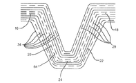
図1は、Z面内において湾曲した縦長部分12と、直線的な縦長部分14とを含む複合部品10の一実施形態の斜視図である。複合部品10は、補強材の積層から作製することができ、航空機の部品、航空機の骨組み、航空機の縦通材、或いは航空機以外の部品、デバイス、又は構造を含みうる。湾曲した縦長部分12は、フランジ部材16及び18、ウェブ部材20及び22、並びにキャップ部材24を含むことができる。
FIG. 1 is a perspective view of one embodiment of a
図2は、図1に示す複合部品10の実施形態の湾曲した縦長部分12のライン2−2における断面図である。図示のように、湾曲した縦長部分12は、異なる種類/方向の補強材を有する積み重ねられた複数の補強層26から構成することができる。他の実施形態では、補強積層26は、様々な材料から作製することができる。45°(PX)の織り布29からなる複数の層28は、フランジ部材16からウェブ部材20、キャップ部材24、ウェブ部材22、及びフランジ部材18に亘って連続することができる。45°(PX)の織り布29からなる他の層31は、ウェブ部材20から、キャップ部材24を介してウェブ部材22に連続し、フランジ部材16及び18中に延びることができる。45°(PX)の織り布29からなるまた別の層35は、フランジ部材16及び18に延びることなく、ウェブ部材20、キャップ部材24、及びウェブ部材22の周囲37に連続して延びることができる。図3は、図2の実施形態の断面図に示す45°の織り布29の一部の、ライン3−3における断面図を平面図に変換したものである。45°の織り布29は、補強材の層33に対して45°の角度に、補強材の層30を含むことができる。
FIG. 2 is a cross-sectional view of the curved
図2に示すように、0/90°(PW「平織り」)の織り布34の層39は、湾曲した縦長部分12に沿って非連続に延びることができる。0/90°の織り布34は、フランジ部材16からウェブ部材20の途中まで延びることができる。0/90°の織り布34はまた、フランジ18からウェブ部材22の途中まで延びることができる。0/90°の織り布34は、キャップ部材24に延びなくてもよい。ウェブ部材20、キャップ部材24、及びウェブ部材22の0/90°の、織り布34が存在しない部分には、一又は複数の窓36を設けることができる。このような窓36は、湾曲した縦長部分12のシワ寄りを軽減及び/又は防止することができる。図4は、図2の実施形態の断面図に示す0/90°の織り布34のライン4−4における断面図を平面図に変換したものである。0/90°の織り布34は、補強材の層40に垂直な補強材の層38を含むことができる。
As shown in FIG. 2, the layer 39 of
図2に示すように、90°の補強材42からなる層41は、ウェブ部材20の途中から、キャップ部材24を通って、ウェブ部材22の途中までしか延びていない。90°の補強材42は、フランジ部材16又は18には延びず、ウェブ部材20及び22の部分44及び46にも延びていない。ウェブ部材20、キャップ部材24、及びウェブ部材22の、90°の補強材42が存在しない部分には、一又は複数の窓48があってよい。このような窓48は、湾曲した縦長部分12のシワ寄りを軽減及び/又は防止することができる。図5は、図2の実施形態の断面図に示す90°の補強材42のライン5−5における断面図を、平面図に変換したものである。90°の補強材42は、補強材50からなる平行な層を含むことができる。
As shown in FIG. 2, the layer 41 made of the 90 ° reinforcing material 42 extends only from the middle of the
図2に示すように、0°の補強材52からなる層43は、キャップ部材24の一部のみに配置することができる。0°の補強材52からなる層は、ウェブ部材20及び22に延びることができるが、フランジ部材16又は18には延びていない。ウェブ部材20及び22、並びにキャップ部材24の、補強材が存在しない部分には、一又は複数の窓54を設けることができる。このような窓54は、湾曲した縦長部分12のシワ寄りを軽減及び/又は防止することができる。図6は、図2の実施形態の断面図に示す0°の補強材52のライン6−6における断面図を、平面図に変換したものである。0°の補強材52は、図5の補強材50に垂直な補強材56からなる平行な層を含むことができる。
As shown in FIG. 2, the layer 43 made of the 0 ° reinforcing material 52 can be disposed only on a part of the
図2に示すように、湾曲した縦長部分12は、航空機の外板及び/又は他の種類の航空機の部品或いは航空機以外の部品を含みうる部材58に取り付けることができる。湾曲した縦長部分12と前記部材58の間の追加的支持として、複数のフィラー部材60を取り付けることができる。
As shown in FIG. 2, the curved
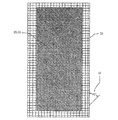
図7は、図1の複合部品10の底面図を示し、点線は、湾曲した縦長部分12の補強層26に設けられた各窓36、48、及び54を示している。窓36、48、及び54は、湾曲した縦長部分12のシワ寄りを軽減及び/又は防止することができる。
FIG. 7 shows a bottom view of the
図8は、図1の複合部品10の実施形態の直線的な縦長部分14のライン8−8における断面図である。図示のように、直線的な縦長部分14は、第2の積み重ねられた複数の補強層64を含むことができる。第2の複数の補強積層64は、フランジ部材16からウェブ部材20、キャップ部材24、ウェブ部材22及びフランジ部材18に亘って連続する45°(PX)の織り布29からなる層を含むことができる。第2の複数の補強積層64は、更に、フランジ部材16からウェブ部材20、キャップ部材24、ウェブ部材22、及びフランジ部材18に亘って連続する0/90°(PW「平織り」)の織り布34の層を含むことができる。シワ寄りは、直線的な縦長部分14においては問題ではなく、45°(PX)の織り布29の層と、0/90°(PW「平織り」)の織り布34の層とを、補強層64に窓を用いずに、フランジ部材16及び18、ウェブ部材20及び22、並びにキャップ部材24に亘って連続させることができる。
FIG. 8 is a cross-sectional view taken along line 8-8 of the straight
図9は、図1に示す複合部品の実施形態の湾曲した縦長部分12のライン9−9における断面図の別の実施形態を示す。図9の断面図と図2の断面図との相違点は、図9では、0/90°の織り布34が、フランジ部材16及び18内と、ウェブ部材20及び22のいずれかの中に延びているが、キャップ24部材内には延びていないことのみとすることができる。その結果、0/90°の補強材を含まない窓36を拡大することができる。
FIG. 9 shows another embodiment of a cross-sectional view at line 9-9 of the curved
図10は、X−Y平面内において湾曲した縦長部分112と、航空機の外板及び/又は他の種類の航空機部品あるいは航空機以外の部品を含みうる部材158に取り付けられる直線的な縦長部分114とを含む複合部品110の一実施形態の斜視図を示す。複合部品110は、補強材の積層から作製することができ、航空機の部品、航空機の骨組み、航空機の縦通材、或いは航空機以外の部品、デバイス又は構造でありうる。湾曲した縦長部分112は、フランジ部材116及び118、ウェブ部材120及び122、並びにキャップ部材124を含むことができる。
FIG. 10 shows a
図11は、図10に示す複合部品110の実施形態の湾曲した縦長部分112のライン11−11における断面図を示す。図示のように、湾曲した縦長部分112は、異なる種類/方向の補強材を有する複数の補強積層126を含むことができる。補強積層126は、一又は複数の種類の補強材から作製することができる。他の実施形態では、補強積層126は様々な材料から作製することができる。45°(PX)の織り布129からなる複数の層128は、フランジ部材116からウェブ部材120、キャップ部材124、ウェブ部材122、及びフランジ部材118に亘って連続することができる。
FIG. 11 shows a cross-sectional view at line 11-11 of the curved
図11に示すように、0/90°(PW「平織り」)の織り布134の層は、湾曲した縦長部分112に沿って連続していなくともよい。0/90°の織り布134は、ウェブ部材120にのみ配置することができ、フランジ部材116及び118、或いはキャップ部材124には含まれなくてよい。他の実施形態では、0/90°の織り布134は、フランジ部材116及び118の途中までしか延びずともよく、キャップ部材124中に延びていなくてよい。フランジ部材116及び118、並びにキャップ部材124の、0/90°の織り布134を含まない部分には、一又は複数の窓136を設けることができる。このような窓136は、湾曲した縦長部分112のシワ寄りを軽減及び/又は防止することができる。
As shown in FIG. 11, the layer of woven
図11に示すように、0°の補強材152からなる非連続的な幅狭のストリップ又はトウは、各ストリップ又はトウの間に名目上のギャップを有し、フランジ部材116及び118からウェブ部材120を通ってキャップ部材124中へと延びることができる。このような窓154は、湾曲した縦長部分112のシワ寄りを軽減及び/又は防止することができる。
As shown in FIG. 11, a non-continuous narrow strip or tow of 0 °
図11に示すように、湾曲した縦長部分112は、航空機の外板及び/又は他の種類の航空機部品或いは航空機以外の部品を含みうる部材に取り付けることができる。複数のフィラー部材160を、追加的な支持として、湾曲した縦長部分112と部材158との間に取り付けることができる。
As shown in FIG. 11, the curved
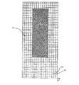
図12は、図10の複合部品110の底面図を示し、点線は、湾曲した縦長部分112の0/90°(PW「平織り」)の織り布からなる層134に設けられた窓136、148、及び154内部の、0°の補強材からなる非連続的な幅狭のストリップ又はトウを示している。窓136、148、及び154は、湾曲した縦長部分112のシワ寄りを軽減及び/又は防止することができる。
FIG. 12 shows a bottom view of the
図13は、図10に示す複合部品110の実施形態の、直線的な縦長部分114のライン13−13における断面図である。図示のように、直線的な縦長部分114は、第2の積み重ねられた複数の補強層164を含むことができる。第2の複数の補強積層164は、フランジ部材116からウェブ部材120、キャップ部材124、ウェブ部材122及びフランジ部材118に亘って連続する45°(PX)の織り布29からなる層を含むことができる。第2の複数の補強積層164は、更に、フランジ部材116からウェブ部材120、キャップ部材124、ウェブ部材122、及びフランジ部材118に亘って連続する0/90°(PW「平織り」)の織り布134の層を含むことができる。シワ寄りは、直線的な縦長部分114においては問題ではなく、45°(PX)の織り布29の層と、0/90°(PW「平織り」)の織り布134の層とを、0/90°(PW「平織り」)の織り布の層164に窓を用いずに、フランジ部材116及び118、ウェブ部材120及び122、並びにキャップ部材124に亘って連続させることができる。
FIG. 13 is a cross-sectional view of the embodiment of the
図14は、複合部品10/110の製造方法のフローチャート266の一実施形態を示す。一のステップ268では、縦長の複合部品10/110を準備/積層する。準備/積層された縦長の複合部品10/110は、非連続的な平織り(PW)0/90°の織り布34/134、及び非連続的な0°の補強材52/152のうちの少なくとも一方を有する補強層26/126を積層すること、窓36/48/54/136/148/154の形状が極めて複雑な領域の周辺に窓プライを配置すること、及び窓36/48/54/136/148/154の中に構造補強プライを追加することを含むことができる。積層された補強層26/126は、様々な補強剤から作製することができる。他の実施形態では、積層された補強層26/126は、様々な材料から作製することができる。準備ステップ268は、直線的/平坦な補強材の積層26/126を有する縦長の複合部品10/110を含む平坦なチャージの中に、補強材のプライを準備/積層することを含むことができる。準備ステップ268は、更に、直線的な縦長部分14/114を含むことができ、この直線的な縦長部分14/114全体には、連続的な平織り(PW)0/90°の織り布34/134、及び/又は連続的な45°(PX)の織り布29/129が延びている。
FIG. 14 shows one embodiment of a
準備ステップ268では、切断機、積層機、及び/又は他の種類の機器を利用して、直線的/平坦な補強積層26/126の積層及び/又は切断を行うことができる。準備ステップ268は、他に、45°(PX)の織り布29/129と90°の補強材42/142とを更に含む補強層26/126を積み重ねることにより、縦長の複合部品10/110を準備/積層することを含むことができる。準備ステップ268は、積み重ねられた補強積層26/126の各々が、補強積層26/126に一又は複数の窓36/48/54/136/148/154を含むような平坦なパターンを含むように、切断機、積層機、及び/又は別の種類の機器をプログラミングすることを含むことができる。準備ステップは、更に、窓36/48/54/136/148/154内の補強プライ間に、手動で及び/又は機器を使用することにより、セパレータフィルムを挟むことを含むことができる。
In the
別のステップ270では、準備された縦長の複合部品10/110の未硬化の直線的な補強積層26/126を、湾曲した縦長部分12/112に成形する。成形ステップ270は、成形機、型、及び/又は別の種類の成形デバイス、構造、及び/又はプロセスを利用することができる。一実施形態では、成形ステップ270は、未硬化の、直線的な補強積層26/126を使用して、準備された縦長の複合部品10/110の縦長部分12/112を機械により成形すること、成形した縦長部分12/112を、硬化型内に配置すること、フランジ部材16/18/116/118及びウェブ部材10/22/120/122を、必要に応じて真っ直ぐに揃えること、湾曲部分に窓プライを位置決め及び成形すること、セパレータフィルムを除去すること、及び湾曲した縦長部分12/112をシワ無く硬化させることのうちの一又は複数を含むことができる。成形された湾曲縦長部分12/112は、非連続的な平織り(PW)0/90°の織り布34/134からなる一又は複数のプライと、非連続的な0°の補強材52/152とを含むことができる。成形ステップ270は、更に、準備された縦長の複合部品10/110の未硬化の直線的な強化積層26/126を、直線的な縦長部分14/114に成形することを含むことができる。成形された直線的縦長部分14/114は、直線的縦長部分14/114全体に延びる連続的な平織り(PW)0/90°の織り布34/134、及び/又は直線的縦長部分14/114全体に延びる連続的な45°(PX)の織り布29/129を含むことができる。
In another
一実施形態では、準備ステップ268及び成形ステップ270は、航空機の部品、航空機の骨組み、及び航空機の縦通材のうちの少なくとも一つを含む複合部品を準備及び成形することを含むことができる。他の実施形態では、様々な航空機以外の構造、デバイス、又は部品を準備及び成形することができる。
In one embodiment, the
また別の実施形態では、本発明の様々な実施形態に開示される複合部品及び方法は、あらゆる角度の織り布、及び/又はあらゆる角度の補強材を包含及び/又は利用することができる。例えば、所定の角度の織り布、及び/又は所定の角度の補強材に言及している本明細書のあらゆる部分において、織り布の角度及び/又は補強材の角度を変更することが可能である。 In yet another embodiment, the composite parts and methods disclosed in the various embodiments of the present invention can include and / or utilize any angle of woven fabric and / or any angle of reinforcement. For example, in any part of the specification that refers to a woven fabric of a predetermined angle and / or a reinforcing material of a predetermined angle, it is possible to change the angle of the woven fabric and / or the angle of the reinforcing material. .
本発明の一又は複数の実施形態は、一又は複数の既存の複合部品及び/又は製造方法が有する一又は複数の問題を軽減することができる。例えば、本発明の一又は複数の実施形態は、極めて複雑な外形を有する領域に配置されて、シワ及び/又は屈曲の種類の問題を軽減及び/又は排除する複合部品を提供することができ、必要な荷重を支持する補強材の追加に必要な高価な修理を軽減することができ、追加的な補強材の必要性を軽減することにより、費用及び重量を低減することができ、追加的な処理、検査、及び製造ステップの必要性を低減することができ、及び/又は一又は複数の他の種類の問題を軽減することができる。 One or more embodiments of the present invention may alleviate one or more problems with one or more existing composite parts and / or manufacturing methods. For example, one or more embodiments of the present invention can provide a composite part that is placed in a region having a very complex profile to reduce and / or eliminate the problem of wrinkle and / or bend types, Expensive repairs required to add stiffeners to support the required loads can be mitigated, and by reducing the need for additional stiffeners, cost and weight can be reduced and additional The need for processing, inspection, and manufacturing steps can be reduced and / or one or more other types of problems can be reduced.
言うまでもないが、上記の説明は本発明の例示的な実施形態に関するものであること、並びに、請求の範囲に規定される本発明の精神及び範囲から逸脱せずに種々の変更が可能であることを理解されたい。
また、本発明は以下に記載する態様を含む。
(態様1)
複数の補強積層を含む湾曲した縦長部分を含む複合部品であって、湾曲した縦長部分に含まれる強化積層が、集合的に、非連続的な織り布及び非連続的な補強材のうちの少なくとも一方を含んでいる、複合部品。
(態様2)
航空機の部品、航空機の骨組み、及び航空機の縦通材のうちの少なくとも一つを含んでいる、態様1に記載の複合部品。
(態様3)
湾曲した縦長部分に含まれる補強積層が、更に、45°の織り布(PX)、及び90°の補強材のうちの少なくとも一方を含んでいる、態様1に記載の複合部品。
(態様4)
湾曲した縦長部分が、複数のフランジ部材、複数のウェブ部材、及びキャップ部材を含んでいる、態様1に記載の複合部品。
(態様5)
湾曲した縦長部分がZ面内で湾曲しており、ウェブ部材及びキャップ部材の各々が、連続的な平織り(PX)45°の織り布、非連続的な平織り(PW)0/90°の織り布、及び非連続的な0°の補強材のうちの少なくとも一つを含んでいる、態様4に記載の複合部品。
(態様6)
湾曲した縦長部分がX−Y面内で湾曲しており、フランジ部材及びキャップ部材の各々が、平織り(PX)45°の織り布、非連続的な平織り(PW)0/90°の織り布、及び非連続的な0°の補強材のうちの少なくとも一つを含んでいる、態様4に記載の複合部品。
(態様7)
直線的な縦長部分を更に含む、態様1に記載の複合部品。
(態様8)
湾曲した縦長部分に含まれる補強積層が、集合的に、非連続的な平織り(PW)0/90°の織り布、及び非連続的な0°の補強材のうちの少なくとも一方を含んでいる、態様1に記載の複合部品。
(態様9)
複合部品の製造方法であって、
非連続的な織り布及び非連続的な補強材のうちの少なくとも一方を含む補強積層を含む縦長の複合部品を準備することと、
縦長の複合部品を、非連続的な織り布及び非連続的な補強材のうちの少なくとも一方を含む湾曲した縦長部分へと成形することと
を含む方法。
(態様10)
準備ステップ及び成形ステップが、航空機の部品、航空機の骨組み、及び航空機の縦通材のうちの少なくとも一つを準備及び成形することを含んでいる、態様9に記載の方法。
(態様11)
準備ステップが、非連続的な平織り(PW)0/90°の織り布、及び非連続的な0°の補強材のうちの少なくとも一方を含む補強積層を含む縦長の複合部品を準備することを含んでおり、成形ステップが、縦長の複合部品を、非連続的な平織り(PW)0/90°の織り布、及び非連続的な0°の補強材のうちの少なくとも一方を含む湾曲した縦長部分に成形することを含んでいる、態様9に記載の方法。
(態様12)
準備ステップが、直線的な補強積層を含む縦長の複合部品を準備することを含んでいる、態様9に記載の方法。
(態様13)
準備ステップが、45°の織り布(PX)、90°の補強材、及び非連続的な0°の補強材を更に含む補強積層を含む縦長の複合部品を準備することを更に含んでいる、態様9に記載の方法。
(態様14)
成形ステップが、直線的な縦長部分全体に延びる連続的な平織り(PW)0/90°の織り布、直線的な縦長部分全体に延びる連続的な45°の織り布(PX)、及び直線的な縦長部分全体に延びる連続的な0°の補強材のうちの少なくとも一つを含む直線的な縦長部分に、縦長の複合部品を成形することを更に含んでいる、態様9に記載の方法。
(態様15)
成形ステップが、成形機及び型のうちの少なくとも一方を利用する、態様9に記載の方法。
It will be appreciated that the above description is of exemplary embodiments of the invention and that various modifications can be made without departing from the spirit and scope of the invention as defined in the claims. I want you to understand.
Moreover, this invention includes the aspect described below.
(Aspect 1)
A composite part including a curved longitudinal portion including a plurality of reinforcing laminates, wherein the reinforcing laminate contained in the curved longitudinal portion is collectively at least one of a discontinuous woven fabric and a discontinuous reinforcement. A composite part containing one side.
(Aspect 2)
The composite part according to aspect 1, comprising at least one of an aircraft part, an aircraft framework, and an aircraft stringer.
(Aspect 3)
The composite part according to aspect 1, wherein the reinforcing laminate included in the curved longitudinal portion further includes at least one of a 45 ° woven fabric (PX) and a 90 ° reinforcing material.
(Aspect 4)
The composite part according to aspect 1, wherein the curved longitudinal portion includes a plurality of flange members, a plurality of web members, and a cap member.
(Aspect 5)
The curved longitudinal portion is curved in the Z plane, and each of the web member and the cap member is a continuous plain weave (PX) 45 ° woven fabric, a discontinuous plain weave (PW) 0/90 ° weave. A composite part according to aspect 4, comprising at least one of a fabric and a non-continuous 0 ° reinforcement.
(Aspect 6)
The curved longitudinal portion is curved in the XY plane, and each of the flange member and the cap member is a plain weave (PX) 45 ° woven fabric, a discontinuous plain weave (PW) 0/90 ° woven fabric And 5. The composite part of embodiment 4, comprising at least one of non-continuous 0 ° reinforcement.
(Aspect 7)
The composite part of embodiment 1, further comprising a straight longitudinal portion.
(Aspect 8)
The reinforcing laminate included in the curved elongated portion collectively includes at least one of a discontinuous plain weave (PW) 0/90 ° woven fabric and a discontinuous 0 ° reinforcement. The composite part according to Aspect 1.
(Aspect 9)
A method of manufacturing a composite part,
Providing a longitudinal composite component including a reinforcing laminate including at least one of a discontinuous woven fabric and a discontinuous reinforcement;
Forming the elongated composite part into a curved elongated portion comprising at least one of a discontinuous woven fabric and a discontinuous reinforcement;
Including methods.
(Aspect 10)
10. The method of aspect 9, wherein the preparing and forming steps comprise preparing and forming at least one of an aircraft part, an aircraft framework, and an aircraft stringer.
(Aspect 11)
The preparing step comprises preparing a longitudinal composite part comprising a reinforcing laminate comprising at least one of a discontinuous plain weave (PW) 0/90 ° woven fabric and a discontinuous 0 ° reinforcement; A curved longitudinal shape comprising a longitudinally long composite part comprising at least one of a discontinuous plain weave (PW) 0/90 ° woven fabric and a discontinuous 0 ° reinforcement. A method according to aspect 9, comprising molding into parts.
(Aspect 12)
A method according to aspect 9, wherein the preparing step comprises preparing an elongate composite part comprising a linear reinforcing laminate.
(Aspect 13)
The preparing step further comprises providing a longitudinal composite part comprising a reinforcing laminate further comprising a 45 ° woven fabric (PX), a 90 ° reinforcement, and a non-continuous 0 ° reinforcement; The method according to embodiment 9.
(Aspect 14)
The forming step comprises a continuous plain weave (PW) 0/90 ° woven fabric extending over the entire straight longitudinal portion, a continuous 45 ° woven fabric (PX) extending over the entire linear longitudinal portion, and linear 10. The method of aspect 9, further comprising forming the elongated composite part into a linear elongated portion that includes at least one of the continuous 0 ° reinforcements extending across the entire elongated portion.
(Aspect 15)
The method of aspect 9, wherein the molding step utilizes at least one of a molding machine and a mold.
Claims (4)
該湾曲した縦長部分が、第1及び第2のフランジ部材(16、18)、第1及び第2のウェブ部材(20、22)、並びにキャップ部材(24)を含み、該湾曲した縦長部分がZ面内で湾曲しており、
さらに前記複数の補強積層が、それぞれが45°の織り布(PX)を含む2種類の層を含み、該2種類の層が、
第1のフランジ部材(16)から第1のウェブ部材(20)、該キャップ部材(24)、第2のウェブ部材(22)、及び第2のフランジ部材(18)に亘って連続する第1の種類の層(28)、及び
第1及び第2のフランジ部材(16、18)に延びることなく、第1のウェブ部材(20)、キャップ部材(24)、及び第2のウェブ部材(22)の周囲(37)に連続して延びる第2の種類の層(35)、である複合部品。 A composite part including a curved longitudinal portion including a plurality of reinforcing laminates, wherein the reinforcing laminate included in the curved longitudinal portion is collectively a woven fabric having at least one window and a reinforcing member having at least one window. And the composite part further includes a straight longitudinal portion,
The curved elongated portion includes first and second flange members (16, 18), first and second web members (20, 22), and a cap member (24), wherein the curved elongated portion is Curved in the Z plane,
Further, the plurality of reinforcing stacked, each containing two types of layers including a fabric (PX) woven 45 °, the two layers,
First continuous from the first flange member (16) to the first web member (20), the cap member (24), the second web member (22), and the second flange member (18). The first web member (20), the cap member (24), and the second web member (22) without extending to the type of layer (28) and the first and second flange members (16, 18). ) A second type of layer (35) extending continuously around (37).
Applications Claiming Priority (3)
| Application Number | Priority Date | Filing Date | Title |
|---|---|---|---|
| US11/971,766 | 2008-01-09 | ||
| US11/971,766 US8152948B2 (en) | 2008-01-09 | 2008-01-09 | Contoured composite parts |
| PCT/US2008/087529 WO2009088699A1 (en) | 2008-01-09 | 2008-12-18 | Contoured composite parts |
Publications (3)
| Publication Number | Publication Date |
|---|---|
| JP2011512267A JP2011512267A (en) | 2011-04-21 |
| JP2011512267A5 JP2011512267A5 (en) | 2012-02-02 |
| JP5722045B2 true JP5722045B2 (en) | 2015-05-20 |
Family
ID=40616807
Family Applications (1)
| Application Number | Title | Priority Date | Filing Date |
|---|---|---|---|
| JP2010542239A Active JP5722045B2 (en) | 2008-01-09 | 2008-12-18 | Composite parts with curved outer shape |
Country Status (6)
| Country | Link |
|---|---|
| US (2) | US8152948B2 (en) |
| EP (1) | EP2227376B1 (en) |
| JP (1) | JP5722045B2 (en) |
| CN (1) | CN101883674B (en) |
| ES (1) | ES2731453T3 (en) |
| WO (1) | WO2009088699A1 (en) |
Families Citing this family (28)
| Publication number | Priority date | Publication date | Assignee | Title |
|---|---|---|---|---|
| US9586699B1 (en) | 1999-08-16 | 2017-03-07 | Smart Drilling And Completion, Inc. | Methods and apparatus for monitoring and fixing holes in composite aircraft |
| US9625361B1 (en) | 2001-08-19 | 2017-04-18 | Smart Drilling And Completion, Inc. | Methods and apparatus to prevent failures of fiber-reinforced composite materials under compressive stresses caused by fluids and gases invading microfractures in the materials |
| US7249943B2 (en) * | 2003-08-01 | 2007-07-31 | Alliant Techsystems Inc. | Apparatus for forming composite stiffeners and reinforcing structures |
| US9150700B2 (en) * | 2008-09-30 | 2015-10-06 | The Boeing Company | Wrinkle reduction in uncured composite laminates |
| US8282757B2 (en) | 2009-11-10 | 2012-10-09 | Alliant Techsystems Inc. | Automated composite annular structure forming |
| US9662841B2 (en) | 2009-11-10 | 2017-05-30 | Orbital Atk, Inc. | Radially extending composite structures |
| JP5713568B2 (en) * | 2010-02-10 | 2015-05-07 | 三菱航空機株式会社 | Manufacturing method of structural material, structural material |
| US8795567B2 (en) | 2010-09-23 | 2014-08-05 | The Boeing Company | Method for fabricating highly contoured composite stiffeners with reduced wrinkling |
| US8642151B2 (en) * | 2011-01-21 | 2014-02-04 | Albany Engineered Composites, Inc. | Preform and method for reinforcing woven fiber nodes |
| CN102118758B (en) | 2011-01-28 | 2015-06-03 | 中兴通讯股份有限公司 | Frequency spectrum sharing method for GSM (Global System for Mobile Communication) system and LTE (Long Term Evolution) system and systems thereof |
| US9180960B2 (en) * | 2011-06-10 | 2015-11-10 | The Boeing Company | Boron fiber reinforced structural components |
| US8993097B2 (en) | 2011-10-10 | 2015-03-31 | The Boeing Company | Tapered height curved composite stringers and corresponding panels |
| US10654246B2 (en) * | 2012-04-28 | 2020-05-19 | General Electric Company | Composite article and methods therefor |
| US8758879B2 (en) * | 2012-06-24 | 2014-06-24 | The Boeing Company | Composite hat stiffener, composite hat-stiffened pressure webs, and methods of making the same |
| US9120276B2 (en) * | 2012-07-25 | 2015-09-01 | The Boeing Company | Laminated composite bending and stiffening members with reinforcement by inter-laminar metal sheets |
| EP2888095B1 (en) * | 2012-08-21 | 2020-09-30 | Saab Ab | A reinforced structure and a method for manufacturing a reinforced structure |
| ES2576508T3 (en) | 2012-12-26 | 2016-07-07 | Airbus Operations S.L. | Reinforced stringer and its manufacturing procedure |
| JP5959558B2 (en) * | 2014-03-13 | 2016-08-02 | アイシン高丘株式会社 | Composite structure and method for producing the same |
| US9862122B2 (en) | 2014-08-14 | 2018-01-09 | The Boeing Company | Reinforced bladder |
| US9809297B2 (en) * | 2015-08-26 | 2017-11-07 | The Boeing Company | Structures containing stiffeners having transition portions |
| CN108491571B (en) * | 2018-02-09 | 2022-04-05 | 福建睿能科技股份有限公司 | Fabric design method, system and device with storage function |
| EP3584150A1 (en) * | 2018-06-19 | 2019-12-25 | Airbus Operations, S.L.U. | Method for manufacturing a rear section of an aircraft and aircraft rear section manufactured by said method |
| US10919260B2 (en) | 2019-05-09 | 2021-02-16 | The Boeing Company | Composite structure having a variable gage and methods for forming a composite structure having a variable gage |
| US11325689B2 (en) | 2019-05-09 | 2022-05-10 | The Boeing Company | Composite stringer and methods for forming a composite stringer |
| US11325688B2 (en) | 2019-05-09 | 2022-05-10 | The Boeing Company | Composite stringer and methods for forming a composite stringer |
| US10919256B2 (en) | 2019-05-09 | 2021-02-16 | The Boeing Company | Composite structure having a variable gage and methods for forming a composite structure having a variable gage |
| US10913215B2 (en) | 2019-05-09 | 2021-02-09 | The Boeing Company | Composite structure having a variable gage and methods for forming a composite structure having a variable gage |
| US11584502B2 (en) * | 2020-07-29 | 2023-02-21 | The Boeing Company | Composite fabric hat stringers having interleafed tape plies |
Family Cites Families (16)
| Publication number | Priority date | Publication date | Assignee | Title |
|---|---|---|---|---|
| US4606961A (en) | 1984-10-09 | 1986-08-19 | The Boeing Company | Discretely stiffened composite panel |
| GB8829198D0 (en) | 1988-12-14 | 1989-01-25 | Shell Int Research | Improvements in structure materials |
| US5843355A (en) * | 1996-01-24 | 1998-12-01 | The Boeing Company | Method for molding a thermoplastic composite sine wave spar structure |
| DE19825402C1 (en) * | 1998-05-27 | 2000-02-10 | Abb Daimler Benz Transp | Self-supporting composite molding for curved parts of rail vehicle subjected to high mechanical and corrosive stress has open fabric spacer with cross fibers between filled, woven glass filament fabric-reinforced resin layers and gel coats |
| JP2001038752A (en) * | 1999-07-30 | 2001-02-13 | Fuji Heavy Ind Ltd | Apparatus and method for molding composite material curved surface panel |
| US6649006B2 (en) * | 2001-10-09 | 2003-11-18 | Lockheed Martin Corporation | Method of making a waffle stiffener |
| JP4019822B2 (en) * | 2002-07-05 | 2007-12-12 | 株式会社豊田自動織機 | Manufacturing method of fiber reinforced composite material |
| US7249943B2 (en) * | 2003-08-01 | 2007-07-31 | Alliant Techsystems Inc. | Apparatus for forming composite stiffeners and reinforcing structures |
| US7045084B1 (en) * | 2004-02-17 | 2006-05-16 | Northrop Grumman Corporation | Process for making a curved preform made from woven composite materials |
| JP4941811B2 (en) * | 2005-03-31 | 2012-05-30 | 東レ株式会社 | Manufacturing method of preform and FRP molded body |
| US8632653B2 (en) * | 2005-05-03 | 2014-01-21 | The Boeing Company | Method of manufacturing curved composite structural elements |
| US7469735B2 (en) * | 2005-08-03 | 2008-12-30 | The Boeing Corporation | Composite structural element fabricating device and method |
| ES2314581T3 (en) | 2005-12-20 | 2009-03-16 | Saab Ab | RIGIDIZATION ELEMENT AND MANUFACTURING PROCEDURE OF A RIGIDIZATION ELEMENT. |
| JP4779754B2 (en) * | 2006-03-29 | 2011-09-28 | 東レ株式会社 | Prepreg laminate and fiber reinforced plastic |
| JP5161432B2 (en) * | 2006-05-01 | 2013-03-13 | 三菱重工業株式会社 | Method for forming composite material structural member |
| JP4544266B2 (en) * | 2007-05-11 | 2010-09-15 | 株式会社豊田自動織機 | Fiber reinforced composite |
-
2008
- 2008-01-09 US US11/971,766 patent/US8152948B2/en active Active
- 2008-12-18 ES ES08870132T patent/ES2731453T3/en active Active
- 2008-12-18 JP JP2010542239A patent/JP5722045B2/en active Active
- 2008-12-18 CN CN200880118804.4A patent/CN101883674B/en active Active
- 2008-12-18 EP EP08870132.1A patent/EP2227376B1/en active Active
- 2008-12-18 WO PCT/US2008/087529 patent/WO2009088699A1/en active Application Filing
-
2012
- 2012-03-05 US US13/412,568 patent/US8535784B2/en active Active
Also Published As
| Publication number | Publication date |
|---|---|
| ES2731453T3 (en) | 2019-11-15 |
| WO2009088699A1 (en) | 2009-07-16 |
| US8152948B2 (en) | 2012-04-10 |
| US8535784B2 (en) | 2013-09-17 |
| CN101883674A (en) | 2010-11-10 |
| JP2011512267A (en) | 2011-04-21 |
| US20120171410A1 (en) | 2012-07-05 |
| US20090176066A1 (en) | 2009-07-09 |
| EP2227376B1 (en) | 2019-03-20 |
| CN101883674B (en) | 2014-11-12 |
| EP2227376A1 (en) | 2010-09-15 |
Similar Documents
| Publication | Publication Date | Title |
|---|---|---|
| JP5722045B2 (en) | Composite parts with curved outer shape | |
| US20130115429A1 (en) | Composite structure and method of forming same | |
| EP2689918B1 (en) | Laminated composite bending and stiffening members with reinforcement by inter-laminar metal sheets | |
| JP4977696B2 (en) | Reinforcing beam, method for manufacturing the reinforcing beam, and fiber laminate | |
| ES2831674T3 (en) | Method and apparatus for fabricating highly contoured composite gussets with reduced wrinkles | |
| US8920698B2 (en) | Production method for a workpiece composed of a fibre-composite material | |
| RU2406604C2 (en) | Method of forming structural element from composite material and structural element from composite material | |
| ES2928481T3 (en) | Seat Lock Rails with Composite Frames | |
| EP2602094B1 (en) | Method of fabricating composite laminate structures allowing ply slippage during forming | |
| BR112015004962B1 (en) | COMPOSITE STRUCTURE, E, METHOD OF PRODUCTION OF A COMPOSITE STRUCTURE | |
| CN103507941A (en) | Composite hat stiffener, composite hat-stiffened pressure webs, and methods of making the same | |
| JP2010533098A (en) | Method for manufacturing an integrated wing structure having a complete outer shape | |
| JP2011512267A5 (en) | ||
| CN111452947A (en) | Shaped composite stringer | |
| US20120027989A1 (en) | Manufacturing method of composite material member and prepreg sheet laminate | |
| US20090115088A1 (en) | Process for Producing a Substantially Shell-Shaped Component | |
| JP5731392B2 (en) | Plane member for aircraft and method for manufacturing the same | |
| EP3000586B1 (en) | Method for manufacturing a composite material part comprising a web and at least one flange | |
| CN107635761A (en) | For produce with can not expansion shape interlayer metal part improved method | |
| US8940214B2 (en) | Method for the manufacture of one or more pairs of components in composite material | |
| EP2868454B1 (en) | Curing tool for shell components and method for curing shell components | |
| ES2955386T3 (en) | Method of manufacturing a composite material structure using a co-curing process | |
| JP2002028944A (en) | Method for molding composite material beam | |
| JP7240559B2 (en) | Manufacturing method for intermediate products of aircraft parts and aircraft parts | |
| US11772344B2 (en) | Product with an array of core elements or voids and interposed sheets and methods for forming such a product |
Legal Events
| Date | Code | Title | Description |
|---|---|---|---|
| A521 | Request for written amendment filed |
Free format text: JAPANESE INTERMEDIATE CODE: A523 Effective date: 20111207 |
|
| A621 | Written request for application examination |
Free format text: JAPANESE INTERMEDIATE CODE: A621 Effective date: 20111207 |
|
| A977 | Report on retrieval |
Free format text: JAPANESE INTERMEDIATE CODE: A971007 Effective date: 20130527 |
|
| A131 | Notification of reasons for refusal |
Free format text: JAPANESE INTERMEDIATE CODE: A131 Effective date: 20130611 |
|
| A521 | Request for written amendment filed |
Free format text: JAPANESE INTERMEDIATE CODE: A523 Effective date: 20130902 |
|
| A02 | Decision of refusal |
Free format text: JAPANESE INTERMEDIATE CODE: A02 Effective date: 20140624 |
|
| A521 | Request for written amendment filed |
Free format text: JAPANESE INTERMEDIATE CODE: A523 Effective date: 20141022 |
|
| A911 | Transfer to examiner for re-examination before appeal (zenchi) |
Free format text: JAPANESE INTERMEDIATE CODE: A911 Effective date: 20141031 |
|
| A131 | Notification of reasons for refusal |
Free format text: JAPANESE INTERMEDIATE CODE: A131 Effective date: 20141209 |
|
| A521 | Request for written amendment filed |
Free format text: JAPANESE INTERMEDIATE CODE: A523 Effective date: 20150129 |
|
| TRDD | Decision of grant or rejection written | ||
| A01 | Written decision to grant a patent or to grant a registration (utility model) |
Free format text: JAPANESE INTERMEDIATE CODE: A01 Effective date: 20150224 |
|
| A61 | First payment of annual fees (during grant procedure) |
Free format text: JAPANESE INTERMEDIATE CODE: A61 Effective date: 20150325 |
|
| R150 | Certificate of patent or registration of utility model |
Ref document number: 5722045 Country of ref document: JP Free format text: JAPANESE INTERMEDIATE CODE: R150 |
|
| R250 | Receipt of annual fees |
Free format text: JAPANESE INTERMEDIATE CODE: R250 |
|
| R250 | Receipt of annual fees |
Free format text: JAPANESE INTERMEDIATE CODE: R250 |
|
| R250 | Receipt of annual fees |
Free format text: JAPANESE INTERMEDIATE CODE: R250 |
|
| R250 | Receipt of annual fees |
Free format text: JAPANESE INTERMEDIATE CODE: R250 |
|
| R250 | Receipt of annual fees |
Free format text: JAPANESE INTERMEDIATE CODE: R250 |
|
| R250 | Receipt of annual fees |
Free format text: JAPANESE INTERMEDIATE CODE: R250 |
|
| R250 | Receipt of annual fees |
Free format text: JAPANESE INTERMEDIATE CODE: R250 |