JP5721383B2 - Fireproof panel connection structure - Google Patents
Fireproof panel connection structure Download PDFInfo
- Publication number
- JP5721383B2 JP5721383B2 JP2010218325A JP2010218325A JP5721383B2 JP 5721383 B2 JP5721383 B2 JP 5721383B2 JP 2010218325 A JP2010218325 A JP 2010218325A JP 2010218325 A JP2010218325 A JP 2010218325A JP 5721383 B2 JP5721383 B2 JP 5721383B2
- Authority
- JP
- Japan
- Prior art keywords
- fireproof
- panels
- calcium silicate
- adjacent
- core material
- Prior art date
- Legal status (The legal status is an assumption and is not a legal conclusion. Google has not performed a legal analysis and makes no representation as to the accuracy of the status listed.)
- Active
Links
- 239000011162 core material Substances 0.000 claims description 43
- 229910052918 calcium silicate Inorganic materials 0.000 claims description 31
- 239000000378 calcium silicate Substances 0.000 claims description 31
- OYACROKNLOSFPA-UHFFFAOYSA-N calcium;dioxido(oxo)silane Chemical compound [Ca+2].[O-][Si]([O-])=O OYACROKNLOSFPA-UHFFFAOYSA-N 0.000 claims description 31
- 230000009970 fire resistant effect Effects 0.000 claims description 13
- 239000000919 ceramic Substances 0.000 claims description 9
- 239000000835 fiber Substances 0.000 claims description 9
- 229910052751 metal Inorganic materials 0.000 claims description 8
- 239000002184 metal Substances 0.000 claims description 8
- 238000005452 bending Methods 0.000 claims description 2
- 238000005192 partition Methods 0.000 description 16
- 238000010438 heat treatment Methods 0.000 description 5
- 239000011810 insulating material Substances 0.000 description 4
- 239000000853 adhesive Substances 0.000 description 3
- 230000001070 adhesive effect Effects 0.000 description 3
- 239000000463 material Substances 0.000 description 3
- 238000003780 insertion Methods 0.000 description 2
- 230000037431 insertion Effects 0.000 description 2
- 238000005259 measurement Methods 0.000 description 2
- 239000011490 mineral wool Substances 0.000 description 2
- OYPRJOBELJOOCE-UHFFFAOYSA-N Calcium Chemical compound [Ca] OYPRJOBELJOOCE-UHFFFAOYSA-N 0.000 description 1
- BPQQTUXANYXVAA-UHFFFAOYSA-N Orthosilicate Chemical compound [O-][Si]([O-])([O-])[O-] BPQQTUXANYXVAA-UHFFFAOYSA-N 0.000 description 1
- 239000002253 acid Substances 0.000 description 1
- 229910052791 calcium Inorganic materials 0.000 description 1
- 239000011575 calcium Substances 0.000 description 1
- 238000002474 experimental method Methods 0.000 description 1
- 229910010272 inorganic material Inorganic materials 0.000 description 1
- 239000011147 inorganic material Substances 0.000 description 1
- 238000009413 insulation Methods 0.000 description 1
- 239000000779 smoke Substances 0.000 description 1
Images


Description
本発明は、耐火間仕切壁等に用いられる耐火パネルの連結部構造の技術分野に関するものである。 The present invention relates to a technical field of a connection structure of a fireproof panel used for a fireproof partition wall or the like.
一般に、耐火間仕切壁は、防火区画、排煙区画、避難区画等を形成するために広く活用されているが、この場合に、複数の耐火パネル同士を連結して耐火間仕切壁を構築することがある。この様な耐火間仕切壁に用いられる耐火パネルとして、例えば、二枚の金属製の表面板間に耐火断熱性の芯材を充填した耐火パネルが知られている(例えば、特許文献1、特許文献2参照)。
ところで、前記二枚の金属製の表面板間に断熱性の芯材を充填した耐火パネルを用いて耐火間仕切壁を形成する場合には、耐火パネル同士の連結部の耐火性能が問題になる。つまり、火災等の高温下においては、熱により表面板と芯材との接着が剥がれると共に表面板が変形し、これにより耐火パネル同士の連結部に隙間が生じて該隙間から火炎や熱が漏れて延焼してしまう惧れがある。
そこで、前記特許文献1のものでは、耐火パネルの両端部に嵌合凸部と嵌合凹部とを形成し、これら嵌合凸部と嵌合凹部部分に無機質材を充填して不燃部を構成している。また、特許文献2のものでは、隣接する耐火パネルの表面板同士の連結を、嵌合凹部と嵌合突部との嵌合と、差込突部と差込受け部との嵌合の二重構造にすることにより、火災時でも表面板同士の連結を維持することを図っている。
In general, fireproof partition walls are widely used to form fireproof compartments, smoke exhaust compartments, evacuation compartments, etc.In this case, it is possible to construct a fireproof partition wall by connecting a plurality of fireproof panels. is there. As a fire-resistant panel used for such a fire-resistant partition wall, for example, a fire-resistant panel in which a fire-resistant and heat-insulating core material is filled between two metal surface plates is known (for example,
By the way, when forming a fireproof partition wall using the fireproof panel which filled the heat insulating core material between the said 2 metal surface plates, the fireproof performance of the connection part of fireproof panels becomes a problem. In other words, under high temperatures such as a fire, the adhesion between the surface plate and the core material is peeled off due to heat and the surface plate is deformed. As a result, a gap is formed in the connecting portion between the fireproof panels, and flame and heat leak from the gap. There is a risk of fire spreading.
Therefore, in the thing of the said
しかしながら、前記特許文献1のものは、火災時等の高温下において、熱により嵌合凸部、嵌合凹部の外殻を形成する金属製の表面板が変形してしまうと、嵌合凸部と嵌合凹部との嵌合を維持することができずにパネル同士の連結部に隙間が生じてしまう惧れがある。また、特許文献2のように耐火パネルの表面板同士の連結を二重構造にしても、高温下(例えば、500度以上)では金属製の表面板の熱膨張変形は大きく、表面板同士の連結が外れてしまう惧れを払拭できないという問題がある。さらに、特許文献2のものでは、耐火パネルの芯材の端縁に端縁ボード部及び目地部が貼着されているが、高温下では芯材と端縁ボード部及び目地部とを貼着する接着材の接着能力が低下して、芯材と端縁ボード部及び目地部との間に隙間が生じてしまう惧れがある。而して、特許文献1、2のものは何れも連結部に隙間が生じる惧れがあって、加熱側から非加熱側に火炎や熱が漏れてしまうことを確実に防止できないという問題があり、ここに本発明の解決すべき課題がある。
However, the thing of the said
本発明は、上記の如き実情に鑑みこれらの課題を解決することを目的として創作されたものであって、請求項1の発明は、二枚の金属製の表面板間に耐火断熱性の芯材を充填してなる耐火パネル同士を連結するにあたり、隣接する耐火パネルの芯材の連結側端面に、表面板と平行状の凹溝を形成し、該凹溝に、隣接する両方の耐火パネルの芯材に亘り、且つ表面板と平行状になるようにケイ酸カルシウム板を嵌合せしめる一方、隣接する耐火パネルの表面板同士にパネル厚方向に重なり合って積層する積層部が設けられていると共に、二枚の表面板は、凹溝までには至らない状態で連結側端面に沿うよう折曲されていて、ケイ酸カルシウム板が凹溝に直接当接する状態で嵌合している一方、隣接する耐火パネルの連結側端面間同士は離間していて対向間に隙間があるものとし、表面板は、連結側端面に沿う状態で凹溝側に向けて折曲したものが、凹溝に至る以前の段階で隣接耐火パネルの連結端面に向けて折曲して突出辺が形成されたものであり、隣接耐火パネルの突出辺同士はケイ酸カルシウム板とは間隙を存した状態でパネル厚方向に積層された積層部となり、該積層部がケイ酸カルシウム板には至らない長さの螺子を用いて止着されていることを特徴とする耐火パネルの連結部構造である。
請求項2の発明は、隣接する耐火パネルの芯材の連結側端面間に、前記ケイ酸カルシウム板に直交する状態で該ケイ酸カルシウム板から表面板に至るようセラミックファイバーを介装させたことを特徴とする請求項1記載の耐火パネルの連結部構造である。
The present invention was created with the object of solving these problems in view of the above circumstances, and the invention of
In the invention of
請求項1の発明とすることにより、火災等の高温下において、熱により表面板が芯材から剥がれたり熱膨張変形したりしても、耐火パネルの連結部は、隣接する両方の耐火パネルの芯材に亘るように配されたケイ酸カルシウム板によって、加熱側面から非加熱側面への火炎や熱の通過経路が確実に遮断されることになる。しかも、前記ケイ酸カルシウム板は、芯材の連結側端面に形成された凹溝に嵌合されることによって、隣接する両方の耐火パネルの芯材に亘るように配される構成であるから、高熱下であっても、ケイ酸カルシウム板が芯材から外れてしまったり、ケイ酸カルシウム板と芯材との間に隙間が生じてしまう惧れがなく、而して、耐火性能に優れた連結部構造とすることができる。
According to the invention of
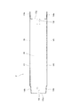
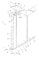
以下、本発明の実施の形態について、図面に基づいて説明する。図3から図6は参考例であり、図7が本発明の第一、第二の実施の形態のものであるが、図において、1は耐火間仕切壁であって、該耐火間仕切壁1の壁面は、複数枚の耐火パネル2を該耐火パネル2の幅方向に並設して形成されていると共に、これら複数枚の耐火パネル2は、天井部3に配設される上部レール4と、床部5に配設される下部レール6と、壁面7に配設される壁レール8とに取付支持されている。
Hereinafter, embodiments of the present invention will be described with reference to the drawings. FIGS. 3 to 6 are reference examples, and FIG. 7 shows the first and second embodiments of the present invention. In the figure,
前記上部レール4及び下部レール6は、耐火間仕切壁1により区画される一方の区画側から耐火パネル2を支持する一半側と、他方の区画側から耐火パネル2を支持する他半側とに二分割されている。そして、これら二分割された上部レール4及び下部レール6は、それぞれコンクリート用螺子9により天井部3及び床部5に固定されると共に、耐火パネル2の上端部及び下端部が螺子10により止着されるようになっている。尚、耐火パネル2の上端面と天井部3との間、耐火パネル2の下端面と床部5との間には、セラミックファイバー等から形成される耐火断熱材11が充填されている。
The
また、壁レール8は、並設される耐火パネル2のうち両端側に配される耐火パネル2を取付支持するものであって、該壁レール8は、壁レール取付金具12を介して壁面7に固定される構成になっているが、これら壁レール8及び壁レール取付金具12も、前記上部レール4及び下部レール6と同様に、耐火間仕切壁1により区画される一方の区画側から耐火パネル2を支持する一半側と、他方の区画側から耐火パネル2を支持する他半側とに二分割されている。そして、壁レール8は、コンクリート用螺子9により壁面7に固定された壁レール取付金具12に螺子13により止着されると共に、耐火パネル2の壁面側端部が螺子10により止着されるようになっている。尚、該耐火パネル2の壁面側端面と壁面7との間には、セラミックファイバー等から形成される耐火断熱材11が充填されている。
The
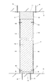
一方、前記耐火パネル2は、平行な二枚の金属製の表面板14間に、耐火断熱性の芯材15を充填して形成されるものであって、本実施の形態では、芯材15としてロックウールが用いられている。尚、表面板14と芯材15とは、図2、3、4に点線で示す接着材16により接着されている。
On the other hand, the fire-
17は前記耐火パネル2同士の連結部であって、該連結部17において、隣接する耐火パネル2の表面板14同士は雄雌状に係合するように構成されている。つまり、耐火パネル2の一方の連結側端部(図3、4において右側端部)における二枚の表面板14は、該耐火パネル2の芯材15の連結側端面15aよりも隣接する耐火パネル2に向けて直線状に延びてから芯材15の連結側端面15aに戻って沿うように折り返されており、これにより、隣接する耐火パネル2に向けて突出する突出部14aが形成されている。また、耐火パネル2の他方の連結側端部(図3、4において左側端部)は、耐火パネル2の厚み方向の寸法が他の部分よりも若干狭くなるように設計されており、これにより他方の連結側端部において二枚の表面板14は、他の部分よりも厚み方向内側に凹んだ凹部14bに形成されている。そして、該凹部14bの厚み方向外側に隣接する耐火パネル2の突出部14aが係合することで、隣接する耐火パネル2の表面板14同士が雄雌状に係合するようになっており、これによって隣接する耐火パネル2の表面板14同士にパネル厚方向に重なり合って積層する積層部が設けられている。
さらに、前記連結部17において、隣接する耐火パネル2の芯材15の連結側端面15a同士は、表面板14に対して直交する状態で互いに対向していると共に、該芯材15の連結側端面15aには、表面板14と平行状の凹溝18が、耐火パネル2の厚み方向中央部に位置し、且つ耐火パネル2の上下方向全長に亘る状態で形成されている。そして、該凹溝18には、隣接する両方の耐火パネル2の芯材15に亘り、且つ表面板14と平行状になるようにしてケイ酸カルシウム板19が嵌合されている。該ケイ酸カルシウム板は、周知のように、耐火性、断熱性、強度、安全性に優れた耐火断熱材であるが、図3、4から明らかなように、表面板14は、凹溝18までには至らない状態で連結側端面15aに沿うよう折曲されていて、ケイ酸カルシウム板19が凹溝18に直接当接する状態で嵌合している。
Further, in the connecting
さらに、隣接する耐火パネル2の芯材15の連結側端面15a間には、前記ケイ酸カルシウム板19に直交する状態で該ケイ酸カルシウム板19から両方の表面板14に至るようにセラミックファイバー20が介装されている。セラミックファイバーは、周知のように、耐火性、断熱性に優れると共に、圧縮性を有した耐火断熱材である。
Furthermore, between the connection side end surfaces 15a of the
叙述の如く構成された本形態において、耐火間仕切壁1の壁面は、二枚の金属製の表面板14間に耐火断熱性の芯材15を充填した耐火パネル2同士を連結して形成されているが、このものにおいて、耐火パネル2の芯材15の連結側端面15aには、表面板14と平行状の凹溝18が形成されていると共に、該凹溝18には、隣接する両方の耐火パネル2の芯材15に亘り、且つ表面板14と平行状になるようにケイ酸カルシウム板19が嵌合されている。さらに、隣接する耐火パネル2の芯材15の連結側端面15a間には、前記ケイ酸カルシウム板19に直交する状態で該ケイ酸カルシウム板19から表面板14に至るようにセラミックファイバー20が介装されている。
In the present embodiment configured as described, the wall surface of the
この結果、火災等の高温下において、熱により表面板14が芯材15から剥がれたり熱膨張変形したりしても、耐火パネル2同士の連結部17は、隣接する両方の耐火パネル2の芯材15に亘るように配されたケイ酸カルシウム板19と、芯材15の連結側端面15a間に介装されたセラミックファイバー20とによって、加熱側面から非加熱側面への火炎や熱の通過経路が確実に遮断されることになる。しかも、前記ケイ酸カルシウム板19は、隣接する耐火パネル2の芯材15の連結側端面15aに形成された凹溝18に嵌合されることによって、隣接する両方の耐火パネル2の芯材15に亘るように配される構成であるから、高熱下であっても、ケイ酸カルシウム板19が芯材15から外れてしまったり、ケイ酸カルシウム板19と芯材15との間に隙間が生じてしまう惧れがなく、而して、耐火パネル2同士の連結部17から火炎や熱が漏れてしまうことを確実に防止することができる。さらにこのものは、隣接する両方の耐火パネル2の芯材15に亘るように配されたケイ酸カルシウム板19によって、耐火パネル2同士の連結が強固になるという利点もある。
As a result, even if the
さらに、本発明が実施された耐火間仕切壁1の耐火性能について、ISO834準拠の一時間耐火試験を行ったところ、図6に示す如く、非加熱側面を合格基準である200℃以下に維持できることが実証され、而して、本発明の有効性を確認することができた。尚、上記実験の際の仕様は、芯材15は80mm厚のロックウール(密度150kg/m3)、ケイ酸カルシウム板19は12mm厚である。また、図6では、耐火試験装置の炉内、非加熱側面について各々1〜3の三箇所の測定温度のデータを示したが、実際の試験では多数箇所の温度を測定し、非加熱側面の全ての測定箇所において200℃以下であった。
Furthermore, when the fire resistance performance of the
本発明は、図7(A)、(B)に示すものが第一、第二の実施の形態であるが、これらのものは、隣接する耐火パネル2の連結部17において表面板14同士を係合するにあたり、如く、隣接する両方の耐火パネル2の表面板14の連結側端部に突出辺14c或いは14dを形成し、これら突出辺14c或いは14d同士を重ね合わせて螺子21或いは22で止着する構成にすることもできる。さらにこれらのものにおいて、螺子21或いは22の止着部分にジョイナー23或いは24を装着しても良い。そしてこれらのものは、図7から明らかなように、積層部を構成する突出辺14c或いは14d同士は、ケイ酸カルシウム板19とは間隙を存した状態でパネル厚方向に積層され、かつケイ酸カルシウム板19には至らない長さの螺子22によって止着されている。
In the present invention, the first and second embodiments shown in FIGS. 7 (A) and 7 (B) are the first and second embodiments. When engaging, as shown in the drawing, projecting
本発明は、耐火間仕切壁等に用いられる耐火パネル同士を連結する場合に、耐火性能に優れた耐火パネルの連結部構造として利用することができる。 INDUSTRIAL APPLICATION When connecting the fireproof panels used for a fireproof partition wall etc., this invention can be utilized as a connection part structure of the fireproof panel excellent in fireproof performance.
2 耐火パネル
14 表面板
15 芯材
15a 連結側端面
18 凹溝
19 ケイ酸カルシウム板
20 セラミックファイバー
2
Claims (2)
Between connecting-side end face of the core material of an adjacent refractory panels, according to claim 1, characterized in that it is interposed a ceramic fiber to reach the laminate part from the calcium silicate board in a state perpendicular to the calcium silicate board Connection structure of the fireproof panel described.
Priority Applications (1)
| Application Number | Priority Date | Filing Date | Title |
|---|---|---|---|
| JP2010218325A JP5721383B2 (en) | 2010-09-29 | 2010-09-29 | Fireproof panel connection structure |
Applications Claiming Priority (1)
| Application Number | Priority Date | Filing Date | Title |
|---|---|---|---|
| JP2010218325A JP5721383B2 (en) | 2010-09-29 | 2010-09-29 | Fireproof panel connection structure |
Publications (3)
| Publication Number | Publication Date |
|---|---|
| JP2012072601A JP2012072601A (en) | 2012-04-12 |
| JP2012072601A5 JP2012072601A5 (en) | 2013-12-05 |
| JP5721383B2 true JP5721383B2 (en) | 2015-05-20 |
Family
ID=46169049
Family Applications (1)
| Application Number | Title | Priority Date | Filing Date |
|---|---|---|---|
| JP2010218325A Active JP5721383B2 (en) | 2010-09-29 | 2010-09-29 | Fireproof panel connection structure |
Country Status (1)
| Country | Link |
|---|---|
| JP (1) | JP5721383B2 (en) |
Cited By (2)
| Publication number | Priority date | Publication date | Assignee | Title |
|---|---|---|---|---|
| JP2018080529A (en) * | 2016-11-17 | 2018-05-24 | 清水建設株式会社 | Connection structure of fireproof panel |
| JP2020204159A (en) * | 2019-06-14 | 2020-12-24 | 三和シヤッター工業株式会社 | Connecting structure of fireproof panel |
Families Citing this family (2)
| Publication number | Priority date | Publication date | Assignee | Title |
|---|---|---|---|---|
| WO2020262611A1 (en) * | 2019-06-28 | 2020-12-30 | 株式会社フジタ | Insulation panel |
| CN114737729A (en) * | 2022-05-17 | 2022-07-12 | 优博特建筑科技(江苏)有限公司 | Building air pipe's fire prevention parcel structure |
Family Cites Families (9)
| Publication number | Priority date | Publication date | Assignee | Title |
|---|---|---|---|---|
| JPS5634090Y2 (en) * | 1978-03-24 | 1981-08-12 | ||
| JPS5663711U (en) * | 1979-10-23 | 1981-05-28 | ||
| JPS622100Y2 (en) * | 1980-08-04 | 1987-01-19 | ||
| JPS63884Y2 (en) * | 1981-05-06 | 1988-01-11 | ||
| JPH06210783A (en) * | 1993-01-13 | 1994-08-02 | Ig Tech Res Inc | Refractory panel |
| JP3264299B2 (en) * | 1993-11-05 | 2002-03-11 | 株式会社アイジー技術研究所 | Fireproof panel |
| JPH09279715A (en) * | 1996-04-12 | 1997-10-28 | Ig Tech Res Inc | Mounting structure of fire-resisting panel |
| JPH09291621A (en) * | 1996-04-25 | 1997-11-11 | Ig Tech Res Inc | Fitting structure of fire-resistant panel |
| JP2000104365A (en) * | 1998-09-29 | 2000-04-11 | Nippon Light Metal Co Ltd | Joint structure of fire-insulating panel |
-
2010
- 2010-09-29 JP JP2010218325A patent/JP5721383B2/en active Active
Cited By (2)
| Publication number | Priority date | Publication date | Assignee | Title |
|---|---|---|---|---|
| JP2018080529A (en) * | 2016-11-17 | 2018-05-24 | 清水建設株式会社 | Connection structure of fireproof panel |
| JP2020204159A (en) * | 2019-06-14 | 2020-12-24 | 三和シヤッター工業株式会社 | Connecting structure of fireproof panel |
Also Published As
| Publication number | Publication date |
|---|---|
| JP2012072601A (en) | 2012-04-12 |
Similar Documents
| Publication | Publication Date | Title |
|---|---|---|
| JP5721383B2 (en) | Fireproof panel connection structure | |
| JP2011196093A (en) | Inter-layer closing device | |
| KR100923800B1 (en) | Panel wall structure | |
| JP7017388B2 (en) | Fire protection structure of fire protection compartment wall | |
| JP5918491B2 (en) | Steel frame structure | |
| JP2012072601A5 (en) | ||
| GB2462000A (en) | Fire protected security room | |
| KR100671267B1 (en) | Panel for assembly of a compley function | |
| KR101408127B1 (en) | Functional Composite Fire Panel And The Structure Using it | |
| JP7304751B2 (en) | Fireproof cladding structure for walls composed of thermal insulation panels | |
| JP6154688B2 (en) | Refractory treatment material, penetrating portion closing structure, and penetrating portion closing method | |
| JP2016059228A (en) | Sealing device for bus duct, and penetration part structure | |
| JP4547611B2 (en) | Fireproof joint structure | |
| JP6147036B2 (en) | Fireproof structure of wall | |
| JP6555912B2 (en) | Structure of joint between organic heat insulation laminated panels | |
| KR200430159Y1 (en) | Plasterboard composite panel | |
| JP7376256B2 (en) | Connection structure of fireproof panels | |
| KR200415012Y1 (en) | Panel for assembly of a compley function | |
| JP7017389B2 (en) | Fireproof material | |
| JP6215528B2 (en) | Thermal insulation panel | |
| JP5777056B2 (en) | Fireproof panels and panel building materials | |
| JP5115856B2 (en) | Joint structure of fireproof ceiling joints | |
| JP5441878B2 (en) | Partition panel and its mounting structure | |
| JP2005163481A (en) | Fireproof heat insulation sandwich panel | |
| JP2016044424A (en) | Fire door |
Legal Events
| Date | Code | Title | Description |
|---|---|---|---|
| RD02 | Notification of acceptance of power of attorney |
Free format text: JAPANESE INTERMEDIATE CODE: A7422 Effective date: 20120316 |
|
| A711 | Notification of change in applicant |
Free format text: JAPANESE INTERMEDIATE CODE: A711 Effective date: 20121122 |
|
| A521 | Request for written amendment filed |
Free format text: JAPANESE INTERMEDIATE CODE: A821 Effective date: 20121122 |
|
| A621 | Written request for application examination |
Free format text: JAPANESE INTERMEDIATE CODE: A621 Effective date: 20130527 |
|
| A521 | Request for written amendment filed |
Free format text: JAPANESE INTERMEDIATE CODE: A523 Effective date: 20130906 |
|
| RD02 | Notification of acceptance of power of attorney |
Free format text: JAPANESE INTERMEDIATE CODE: A7422 Effective date: 20130926 |
|
| A521 | Request for written amendment filed |
Free format text: JAPANESE INTERMEDIATE CODE: A523 Effective date: 20130926 |
|
| A977 | Report on retrieval |
Free format text: JAPANESE INTERMEDIATE CODE: A971007 Effective date: 20131218 |
|
| A131 | Notification of reasons for refusal |
Free format text: JAPANESE INTERMEDIATE CODE: A131 Effective date: 20140109 |
|
| A521 | Request for written amendment filed |
Free format text: JAPANESE INTERMEDIATE CODE: A523 Effective date: 20140303 |
|
| A131 | Notification of reasons for refusal |
Free format text: JAPANESE INTERMEDIATE CODE: A131 Effective date: 20140814 |
|
| A521 | Request for written amendment filed |
Free format text: JAPANESE INTERMEDIATE CODE: A523 Effective date: 20140925 |
|
| TRDD | Decision of grant or rejection written | ||
| A01 | Written decision to grant a patent or to grant a registration (utility model) |
Free format text: JAPANESE INTERMEDIATE CODE: A01 Effective date: 20150312 |
|
| A61 | First payment of annual fees (during grant procedure) |
Free format text: JAPANESE INTERMEDIATE CODE: A61 Effective date: 20150324 |
|
| R150 | Certificate of patent or registration of utility model |
Ref document number: 5721383 Country of ref document: JP Free format text: JAPANESE INTERMEDIATE CODE: R150 |
|
| R250 | Receipt of annual fees |
Free format text: JAPANESE INTERMEDIATE CODE: R250 |
|
| R250 | Receipt of annual fees |
Free format text: JAPANESE INTERMEDIATE CODE: R250 |
|
| S531 | Written request for registration of change of domicile |
Free format text: JAPANESE INTERMEDIATE CODE: R313531 |
|
| R350 | Written notification of registration of transfer |
Free format text: JAPANESE INTERMEDIATE CODE: R350 |
|
| R250 | Receipt of annual fees |
Free format text: JAPANESE INTERMEDIATE CODE: R250 |
|
| R250 | Receipt of annual fees |
Free format text: JAPANESE INTERMEDIATE CODE: R250 |
|
| R250 | Receipt of annual fees |
Free format text: JAPANESE INTERMEDIATE CODE: R250 |
|
| R250 | Receipt of annual fees |
Free format text: JAPANESE INTERMEDIATE CODE: R250 |
|
| R250 | Receipt of annual fees |
Free format text: JAPANESE INTERMEDIATE CODE: R250 |