JP5718732B2 - Floating flap gate - Google Patents
Floating flap gate Download PDFInfo
- Publication number
- JP5718732B2 JP5718732B2 JP2011123474A JP2011123474A JP5718732B2 JP 5718732 B2 JP5718732 B2 JP 5718732B2 JP 2011123474 A JP2011123474 A JP 2011123474A JP 2011123474 A JP2011123474 A JP 2011123474A JP 5718732 B2 JP5718732 B2 JP 5718732B2
- Authority
- JP
- Japan
- Prior art keywords
- door body
- floating
- flap gate
- standing
- door
- Prior art date
- Legal status (The legal status is an assumption and is not a legal conclusion. Google has not performed a legal analysis and makes no representation as to the accuracy of the status listed.)
- Active
Links
- XLYOFNOQVPJJNP-UHFFFAOYSA-N water Substances O XLYOFNOQVPJJNP-UHFFFAOYSA-N 0.000 claims description 28
- 238000002360 preparation method Methods 0.000 description 6
- 238000012423 maintenance Methods 0.000 description 5
- 239000000463 material Substances 0.000 description 4
- 238000010586 diagram Methods 0.000 description 3
- -1 polyethylene Polymers 0.000 description 3
- 239000004698 Polyethylene Substances 0.000 description 2
- 238000012790 confirmation Methods 0.000 description 2
- 229920000573 polyethylene Polymers 0.000 description 2
- FGRBYDKOBBBPOI-UHFFFAOYSA-N 10,10-dioxo-2-[4-(N-phenylanilino)phenyl]thioxanthen-9-one Chemical compound O=C1c2ccccc2S(=O)(=O)c2ccc(cc12)-c1ccc(cc1)N(c1ccccc1)c1ccccc1 FGRBYDKOBBBPOI-UHFFFAOYSA-N 0.000 description 1
- 239000004952 Polyamide Substances 0.000 description 1
- 239000004743 Polypropylene Substances 0.000 description 1
- 239000004760 aramid Substances 0.000 description 1
- 229920003235 aromatic polyamide Polymers 0.000 description 1
- 230000005540 biological transmission Effects 0.000 description 1
- 230000000903 blocking effect Effects 0.000 description 1
- 238000004140 cleaning Methods 0.000 description 1
- 230000007423 decrease Effects 0.000 description 1
- 230000003111 delayed effect Effects 0.000 description 1
- 239000000835 fiber Substances 0.000 description 1
- 230000005484 gravity Effects 0.000 description 1
- 229920002647 polyamide Polymers 0.000 description 1
- 229920001230 polyarylate Polymers 0.000 description 1
- 229920000728 polyester Polymers 0.000 description 1
- 229920001155 polypropylene Polymers 0.000 description 1
Images


Description
本発明は、例えば防波堤の開口部に設置され、増水時、増水した水が生活空間や地下空間に流れ込まないように、扉体を浮上させて前記開口部を遮断する浮体式フラップゲートに関するものである。 The present invention relates to a floating flap gate that is installed at, for example, an opening of a breakwater and raises a door to block the opening so that the increased water does not flow into a living space or underground space when the water increases. is there.
増水時に、増水した水が生活空間や地下空間に流れ込まないように、流入しようとする水の浮力を利用して扉体を浮上させ、例えば防波堤の開口部を遮断する浮体式フラップゲートがある(例えば特許文献1)。 There is a floating flap gate that lifts the door body using the buoyancy of the water to be introduced so that the increased water does not flow into the living space or underground space when the water rises, for example, blocking the opening of the breakwater ( For example, Patent Document 1).
しかしながら、特許文献1で開示された浮体式フラップゲートは、流入初期の速度が速い場合には扉体の浮上動作が遅れ、生活空間や地下空間に越流する問題がある。
However, the floating-type flap gate disclosed in
この問題を防止するために、一端にカウンタウエイトを取り付けたロープの他端を、滑車を介して扉体に繋いだ浮体式フラップゲートが提案されている(例えば特許文献2)。 In order to prevent this problem, a floating flap gate has been proposed in which the other end of a rope having a counterweight attached to one end is connected to a door body via a pulley (for example, Patent Document 2).
この特許文献2で提案された浮体式フラップゲートは、カウンタウエイトの重さで浮体式フラップゲートの浮力不足を補うことで、流入初期における扉体の浮上動作の遅れを解決している。
The floating-type flap gate proposed in
しかしながら、特許文献2はもとより特許文献1で開示された浮体式フラップゲートも、津波・高波の来襲によって起立した扉体は、津波・高波が引く際には、水位の低下に伴って倒伏するので、ピット内に流れ込んだ漂流物を挟み込むことが予想される。
However, in the floating flap gate disclosed in
また、浮体式フラップゲートは、特許文献2で開示されたものであっても、水位の上昇を利用して無動力で起立するため、メンテナンス時の作動確認や、津波の来襲に備えた事前準備のための起立を行うことができない。
In addition, even if the floating-type flap gate is disclosed in
本発明が解決しようとする問題点は、従来の浮体式フラップゲートは、津波・高波の来襲によって起立した扉体は、津波・高波が引く際には、水位の低下に伴って倒伏するので、ピット内に流れ込んだ漂流物を挟み込むことが予想されるという点である。また、水位の上昇を利用して無動力で起立するため、メンテナンス時の作動確認や、津波の来襲に備えた事前準備のための起立を行うことができないという点である。 The problem to be solved by the present invention is that the conventional floating-type flap gate, when the tsunami / high wave pulls, the door standing up due to the tsunami / high wave invades, as the water level falls, It is expected that the drifting material that has flowed into the pit will be caught. In addition, since the water level rises to stand up without power, it is impossible to confirm the operation at the time of maintenance or to stand up in advance for preparation for the tsunami attack.
本発明は、上記問題を解決すべく、扉体の起立状態を維持する機能を備えた浮体式フラップゲート、望ましくは更に扉体の開閉する機能を備えた浮体式フラップゲートを提供することを目的としてなされたものである。 In order to solve the above problems, the present invention aims to provide a floating flap gate having a function of maintaining a standing state of a door body, and preferably a floating flap gate having a function of opening and closing the door body. It was made as.
本発明の浮体式フラップゲートは、
開口部或いは出入口に設置され、水が流入する際、前記開口部或いは前記出入口を遮断すべく、前記流入する水の方向に高さ方向の平面内で、基端側を支点として先端側が起立揺動する扉体の先端側に一端を繋いだロープの他端に取付けたカウンタウエイトの重量で前記流入初期の扉体の浮上動作を補助する浮体式フラップゲートであって、
前記ロープを巻き取るドラムの回転軸に、扉体を起立させる方向にのみ回転が可能な一方向クラッチを設置するとともに、前記一方向クラッチを正逆回転させるウオームギヤ減速装置を備えたことを最も主要な特徴としている。
The floating flap gate of the present invention is
When the water flows in, it is installed at the opening or the entrance, and in order to block the opening or the entrance, the distal end side stands up on the base end side as a fulcrum in a plane in the height direction in the direction of the inflowing water. A floating flap gate that assists the floating operation of the door in the initial inflow with the weight of the counterweight attached to the other end of the rope that has one end connected to the distal end side of the moving door,
It is most important that a one-way clutch capable of rotating only in the direction in which the door body is raised is installed on the rotating shaft of the drum that winds the rope, and that a worm gear reduction device that rotates the one-way clutch forward and backward is provided . Features.
上記の本発明では、扉体が起立する際の動作を、起立方向のみの一方向に限定するので、起立時、扉体は倒伏側への不要な揺り戻し動作をすることがない。また、起立完了時には、起立完了状態を維持し、起立状態で作用波力が変動した場合にも扉体が動揺することがない。さらに、津波が引いて水位が低下した際も、扉体は起立状態を維持する。 In the above-mentioned present invention, since the operation when the door body stands is limited to one direction only in the standing direction, the door body does not perform an unnecessary swinging back operation to the lying side when standing. Further, when the standing is completed, the standing completion state is maintained, and the door body does not shake even when the acting wave force fluctuates in the standing state. Furthermore, even when the water level is lowered due to a tsunami, the door body maintains an upright state.
またさらに、平常時の作動確認や、津波の来襲に備えた事前準備のための起立を行うことができる。 Furthermore , it is possible to perform normal operation checks and stand up for preparations in preparation for the tsunami attack.
本発明では、起立時、扉体は倒伏側への不要な揺り戻し動作をすることがない。また、起立完了時には、起立完了状態を維持し、起立状態で作用波力が変動した場合にも扉体が動揺することがない。従って、衝撃的な荷重が扉体に作用するのを防ぐことができる。さらに、津波が引いて水位が低下した際も、起立状態を維持するので、津波が引いた後にピット内に流れ込んだ漂流物の清掃作業を行うことが可能となる。 In the present invention, at the time of standing, the door body does not perform an unnecessary swinging back operation to the lying side. Further, when the standing is completed, the standing completion state is maintained, and the door body does not shake even when the acting wave force fluctuates in the standing state. Therefore, it is possible to prevent an impact load from acting on the door body. Furthermore, since the standing state is maintained even when the water level is lowered due to the tsunami, it is possible to perform the cleaning work of the drifting material that has flowed into the pit after the tsunami has been pulled.
本発明は、扉体の起立状態を維持するという目的を、一端を扉体の先端側に、他端にカウンタウエイトを取り付けたロープを巻き取るワイヤドラムの回転軸に、扉体を起立させる方向にのみ回転が可能な一方向クラッチを設置することで実現した。 The present invention aims at maintaining the standing state of the door body in a direction in which the door body stands on the rotating shaft of a wire drum that winds a rope having one end on the distal end side of the door body and a counterweight attached to the other end. This is achieved by installing a one-way clutch that can only rotate.
以下、本発明を実施するための形態を、図1〜図8を用いて詳細に説明する。
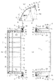
図1は本発明の浮体式フラップゲートの概略構成を示した図である。
Hereinafter, embodiments for carrying out the present invention will be described in detail with reference to FIGS.
FIG. 1 is a diagram showing a schematic configuration of a floating flap gate of the present invention.
図1において、1は例えば防波堤の、開口部の路面rsに設置される2つの浮体を高さ方向に連結した扉体を有する本発明の浮体式フラップゲートである。この浮体式フラップゲート1を構成する扉体2は、先端側2bの浮体が所定の角度だけ起立方向に自由に回動するように成されている。
In FIG. 1,
この浮体式フラップゲート1は、海洋(或いは河川)から生活空間や地下空間に水wが流入しようとする際、流入する水wの水圧を利用して、基端側2aを支点として先端側2bを起立揺動させて開口部を水密状態に遮断するものである。
The floating
この浮体式フラップゲート1を構成する扉体2は、遮断する開口部の幅が広い場合は、複数の扉体2を開口部の幅方向に連結した構成とされ、各扉体2間は扉間水密ゴムによって連結されている。また、両側の扉体2の、防波堤の開口部に設けた戸当りと相対する側には水密ゴムが設けられている。
The
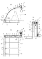
図1〜図7に示す本発明の浮体式フラップゲート1は、例えば複数の扉体2の先端をビーム3によって連結し、その両側に浮力補助装置4を構成するワイヤロープ4aの一端側を接続すると共に、両端にはガイドローラ5を回転自在に取り付けている。
1 to 7, the floating
6は扉体2の先端の起立・倒伏軌跡に合わせて前記開口部の側壁SWの上部に配置したレールであり、扉体2の起立・倒伏時に前記ガイドローラ5を案内する。7は同じく前記側壁SWの上部に配置したロープガイドローラであり、浮力補助装置4を構成するワイヤドラム4bに他端側を巻き付けた前記ワイヤロープ4aを案内する。
図1〜図7に示した実施例では、前記ワイヤドラム4bとカウンタウエイト用のワイヤドラム4cを同一の回転軸4dに直列配置し、カウンタウエイト用のワイヤドラム4cに一端側を巻き付けたカウンタウエイト用ワイヤロープ4eの他端にカウンタウエイト4fを繋いでいる。
In the embodiment shown in FIGS. 1 to 7, the
また、図1〜図7に示した実施例では、前記回転軸4dに扉体2を起立させる方向にのみ回転が可能な一方向クラッチ9を設置し、この一方向クラッチ9に、その回転軸を正逆させて扉体2を起立又は倒伏する扉体開閉装置8を設けている。
In the embodiment shown in FIGS. 1 to 7, a one-
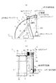
前記一方向クラッチ9は、図8に示すように、前記回転軸4dに連結された軸9aに、扉体2を起立させる方向にのみ回転が可能な機構9b、軸受9cを介してケーシング9dを保持した構成である。
As shown in FIG. 8, the one-
一方、前記扉体開閉装置8は、一方向クラッチ9のケーシング9dに取付けたスプロケット8aと、ウオームギヤ減速装置8bと、このウオームギヤ減速装置8bの出力軸に取付けたスプロケット8cと、両スプロケット8a,8cに掛け渡したチェーン8dと、前記ウオームギヤ減速装置8bの入力軸を正逆回転するハンドル8eとから構成されている。なお、図示省略したが、ウオームギヤ減速装置8bの出力軸にはウオームホイールが、入力軸にはウオームが取り付けられている。
On the other hand, the door body opening /
このウオームギヤ減速装置8bは、出力軸側からの作動を許さないものであれば、その内部機構は限定されない。また、ウオームギヤ減速装置8bから回転軸4dへの動力伝達手段も前記スプロケット8a,8cとチェーン8dを使用したものに限らず、ウオームギヤ減速装置8bと一方向クラッチ9の回転軸間の距離によってはギヤで伝達するものでも良い。さらに、ウオームギヤ減速装置8bを一方向クラッチ9の回転軸近傍の上方位置に設置する場合は、ハンドル8eではなく鎖車等を使用してウオームギヤ減速装置8bを正逆回転しても良い。
The internal mechanism of the worm
また、前記一方向クラッチ9は、一方向のみ自由回転を許し、開閉荷重相当のトルクを伝達できるものであれば、爪車、カムクラッチ等、その形式は限定されない。
The type of the one-
上記構成の浮体式フラップゲート1の機能を以下に説明する。
The function of the floating
(メンテナンス時の作動確認や津波の来襲に備えた事前準備のための起立等:図3参照)
メンテナンス時の作動確認や津波の来襲に備えた事前準備のために扉体2を起立する際は、両側に設けたハンドル8eを同時に例えば正回転して一方向クラッチ9のケーシング9dを回転させる。このケーシング9dの回転と一体で回転軸4dが回転してワイヤドラム4bを正回転させることで、図2に示す平常時の倒伏状態から、扉体2を起立する。この際、ハンドル8eを正回転する力は、後述する流入初期におけるカウンタウエイト4fの補助力により軽減される。この起立操作時、ハンドル8eの回転を中断しても、ウオームギヤ減速装置8bを構成するウオームギヤや一方向クラッチ9の作用により、扉体2が倒伏することはない。
(Operation confirmation during maintenance and stand-up for preparations in preparation for the tsunami attack: See Fig. 3)
When the
また、メンテナンス時の作動確認後に、起立状態から図2に示す平常時の状態に倒伏する場合は、両側に設けたハンドル8eを同時に逆回転して回転軸4dを介してワイヤドラム4bを逆回転させることで、図2に示す平常時の倒伏状態にする。
Further, after the operation is confirmed at the time of maintenance, in the case of lying down from the standing state to the normal state shown in FIG. 2, the
(流入初期時:図4参照)
流入初期は、自らの浮力とカウンタウエイト4fの補助力によって、扉体2の先端側2bの浮体が所定の角度だけ先行して起立する(図4(a)参照。)。この時、ウオームギヤ減速装置8bの出力軸は固定されているが、一方向クラッチ9により回転軸4dは正回転方向に回転するので、カウンタウエイト4fの重力は扉体2を起立させる方向に働く。
(In the initial stage of inflow: see Fig. 4)
At the beginning of the inflow, the floating body on the
(水の流入時:図5参照)
扉体2の先端側2bの浮体が先行して起立した後、さらに水位が上昇すると、扉体2の底部に水圧が作用し、扉体2自らの浮力とカウンタウエイト4fの補助力の合力が扉体2を起立させる方向に働き、扉体2を起立させる。この時、扉体2の起立により弛んだワイヤロープ4aは、カウンタウエイト4fの降下によりワイヤドラム4bに巻き取られる。また、扉体2が起立限まで到達する前に水位が低下しても、一方向クラッチ9の作用によりワイヤドラム4bは逆回転せず、起立状態を維持する。なお、扉体2の起立時は、一方向クラッチ9のケーシング9dは固定され、回転軸4dのみが起立方向へ回転する。
(When water flows in: see Fig. 5)
When the water level rises further after the floating body on the
(起立時)
起立状態にある扉体2は、一方向クラッチ9の作用により、倒伏方向への不要な揺り戻し動作をすることがない。また、起立完了時には、起立完了状態を維持し、起立状態で作用波力が変動した場合にも、扉体2が動揺(起立限→倒伏側への揺動→起立限への復帰)することがない。従って、衝撃的な荷重が扉体2に作用するのを防ぐことができる。また、扉体2にテンションロッド13が設置されている場合(図6参照)は、このテンションロッド13に衝撃的な荷重が作用することも防ぐことができる。
(When standing)
The
(水位低下後:図6参照)
先に説明したように、水の流入により起立した扉体2は、水位が低下しても、一方向クラッチ9の作用によりワイヤドラム4bは逆回転せず、起立状態を維持する。従って、水位が低下した後、扉体2を収納するピット10に漂流物などの異物11が流れ込んでいる場合は、この異物11を撤去した後、両側に設けたハンドル8eを同時に逆回転して回転軸4dを介してワイヤドラム4bを逆回転させ、図2に示す平常時の倒伏状態にする。
(After drop in water level: see Fig. 6)
As described above, even when the water level is lowered, the
上記の本発明の浮体式フラップゲート1において、図7に示すように、ビーム3の突出部3aを隣接する扉体2間に挿入し、この突出部3aと隣接する扉体2をピン12で連結する構造とすれば、当該連結部が隣接する扉体2間の間隔を保持する役割を果たす。その際、扉体2に設けたピン12の受部に、ピン12との間で扉体2の厚さ方向にある程度の隙間dが存在するようにしておけば(図7(b)参照。)、起立時、水圧や波圧荷重は個々の扉体2に分散しながら、複数の扉体2が一枚の壁を形成するように拘束する役目を果たす。
In the above-described floating
本発明は、前記の例に限るものではなく、各請求項に記載の技術的思想の範疇であれば、適宜実施の形態を変更しても良いことは言うまでもない。 The present invention is not limited to the above examples, and it goes without saying that the embodiments may be changed as appropriate within the scope of the technical idea described in each claim.
例えば、前記実施例では、ワイヤロープ4a,4eを使用しているが、ポリアミド系、ポリエステル系、ポリエチレン系、ポリプロピレン系、アラミド系、ポリアリレート系、超高密度ポリエチレンなどの繊維ロープを使用しても良い。
For example, although the
また、上記の実施例では、複数の浮体を高さ方向に連結した浮体連結式フラップゲートを示したが、扉体が単一の浮体で構成された浮体式フラップゲートに適用しても良い。 In the above-described embodiment, the floating body-connected flap gate in which a plurality of floating bodies are connected in the height direction is shown. However, the present invention may be applied to a floating-type flap gate in which the door body is configured by a single floating body.
1 浮体式フラップゲート
2 扉体
3 ビーム
4 浮力補助装置
4a ワイヤロープ
4b ワイヤドラム
4c カウンタウエイト用ワイヤドラム
4d 回転軸
4e カウンタウエイト用ワイヤロープ
4f カウンタウエイト
8 扉体開閉装置
8b ウオームギヤ減速装置
9 一方向クラッチ
DESCRIPTION OF
Claims (1)
前記ロープを巻き取るドラムの回転軸に、扉体を起立させる方向にのみ回転が可能な一方向クラッチを設置するとともに、前記一方向クラッチを正逆回転させるウオームギヤ減速装置を備えたことを特徴とする浮体式フラップゲート。 When the water flows in, it is installed at the opening or the entrance, and in order to block the opening or the entrance, the distal end side stands up on the base end side as a fulcrum in a plane in the height direction in the direction of the inflowing water. A floating flap gate that assists the floating operation of the door in the initial inflow with the weight of the counterweight attached to the other end of the rope that has one end connected to the distal end side of the moving door,
The rotary shaft of the drum that winds up the rope is provided with a worm gear reduction device that is provided with a one-way clutch that can rotate only in the direction in which the door body is raised, and that rotates the one-way clutch forward and backward. Floating flap gate.
Priority Applications (1)
| Application Number | Priority Date | Filing Date | Title |
|---|---|---|---|
| JP2011123474A JP5718732B2 (en) | 2011-06-01 | 2011-06-01 | Floating flap gate |
Applications Claiming Priority (1)
| Application Number | Priority Date | Filing Date | Title |
|---|---|---|---|
| JP2011123474A JP5718732B2 (en) | 2011-06-01 | 2011-06-01 | Floating flap gate |
Publications (3)
| Publication Number | Publication Date |
|---|---|
| JP2012251338A JP2012251338A (en) | 2012-12-20 |
| JP2012251338A5 JP2012251338A5 (en) | 2013-02-07 |
| JP5718732B2 true JP5718732B2 (en) | 2015-05-13 |
Family
ID=47524390
Family Applications (1)
| Application Number | Title | Priority Date | Filing Date |
|---|---|---|---|
| JP2011123474A Active JP5718732B2 (en) | 2011-06-01 | 2011-06-01 | Floating flap gate |
Country Status (1)
| Country | Link |
|---|---|
| JP (1) | JP5718732B2 (en) |
Families Citing this family (7)
| Publication number | Priority date | Publication date | Assignee | Title |
|---|---|---|---|---|
| CN104762933B (en) * | 2015-04-28 | 2016-06-08 | 山东农业大学 | Automatically the hollow gate of water intaking is weighed |
| JP6434874B2 (en) * | 2015-08-10 | 2018-12-05 | 日立造船株式会社 | Floating flap gate |
| CN109204102A (en) * | 2017-07-01 | 2019-01-15 | 青岛春田科技车辆有限公司 | A kind of multi-functional big plate link mechanism of overturning |
| CN107701028B (en) * | 2017-11-13 | 2019-07-05 | 福建奋安铝业有限公司 | Double window frame |
| JP6626180B2 (en) * | 2018-11-09 | 2019-12-25 | 日立造船株式会社 | Floating flap gate |
| JP7211823B2 (en) * | 2019-01-11 | 2023-01-24 | 日立造船株式会社 | relief gate |
| CN114495403B (en) * | 2022-02-21 | 2023-12-19 | 武汉理工光科股份有限公司 | Fire alarm controller with safety protection |
Family Cites Families (3)
| Publication number | Priority date | Publication date | Assignee | Title |
|---|---|---|---|---|
| JPS6160914A (en) * | 1984-09-03 | 1986-03-28 | Kaisei Kogyo Kk | Falling-down weir |
| JPS63138013A (en) * | 1986-11-28 | 1988-06-10 | Kaisei Kogyo Kk | Lifting gear for door unit |
| JP2003253912A (en) * | 2002-03-01 | 2003-09-10 | Kumagai Gumi Co Ltd | Water-level follow-up type rise-fall gate device |
-
2011
- 2011-06-01 JP JP2011123474A patent/JP5718732B2/en active Active
Also Published As
| Publication number | Publication date |
|---|---|
| JP2012251338A (en) | 2012-12-20 |
Similar Documents
| Publication | Publication Date | Title |
|---|---|---|
| JP5718732B2 (en) | Floating flap gate | |
| KR101680172B1 (en) | Floating flap gate | |
| CN104769275B (en) | Bottomless cup type hydraulic conversion device using water flow energy | |
| KR101537881B1 (en) | Waterproof plate device | |
| KR100768082B1 (en) | Switchgear for a floodgate by using a two way wire drum | |
| JP4644734B2 (en) | Flood control equipment | |
| JP5199227B2 (en) | Standing state holding mechanism of flap gate for wave removal | |
| JP5792022B2 (en) | Wall-mounted flap gate waterproof panel | |
| JP5718792B2 (en) | Floating flap gate | |
| JP2007056735A (en) | Water power device | |
| JP4512915B2 (en) | Power generation device by wave force | |
| US7650749B2 (en) | Tidal power station device | |
| US11661925B2 (en) | Apparatuses, systems, and methods for extraction and/or storage of energy from moving fluids | |
| KR200426008Y1 (en) | Switchgear for a floodgate by using a two way wire drum | |
| KR100885968B1 (en) | Apparatus selectively opening and closing floodgate | |
| JP2007528464A (en) | Wind power generator | |
| JP5948206B2 (en) | Floating flap gate | |
| JP2972868B2 (en) | Hydropower equipment | |
| JP4730915B2 (en) | Tidal energy utilization load driving method and apparatus | |
| JP2008106461A (en) | Flush gate | |
| CN112461214A (en) | Beach offshore flow automatic detection emergency device with photovoltaic panels | |
| JP5699888B2 (en) | Floating type undulating gate facility | |
| KR101140230B1 (en) | A movable weir with variable type fishway | |
| JP2004270324A (en) | Flap gate opening/closing machine | |
| JP4120987B2 (en) | Automatic ship gate |
Legal Events
| Date | Code | Title | Description |
|---|---|---|---|
| A521 | Request for written amendment filed |
Free format text: JAPANESE INTERMEDIATE CODE: A523 Effective date: 20121025 |
|
| A621 | Written request for application examination |
Free format text: JAPANESE INTERMEDIATE CODE: A621 Effective date: 20131220 |
|
| A977 | Report on retrieval |
Free format text: JAPANESE INTERMEDIATE CODE: A971007 Effective date: 20140514 |
|
| A131 | Notification of reasons for refusal |
Free format text: JAPANESE INTERMEDIATE CODE: A131 Effective date: 20140701 |
|
| A521 | Request for written amendment filed |
Free format text: JAPANESE INTERMEDIATE CODE: A523 Effective date: 20140811 |
|
| TRDD | Decision of grant or rejection written | ||
| A01 | Written decision to grant a patent or to grant a registration (utility model) |
Free format text: JAPANESE INTERMEDIATE CODE: A01 Effective date: 20150310 |
|
| A61 | First payment of annual fees (during grant procedure) |
Free format text: JAPANESE INTERMEDIATE CODE: A61 Effective date: 20150319 |
|
| R150 | Certificate of patent or registration of utility model |
Ref document number: 5718732 Country of ref document: JP Free format text: JAPANESE INTERMEDIATE CODE: R150 |
|
| R250 | Receipt of annual fees |
Free format text: JAPANESE INTERMEDIATE CODE: R250 |