JP5715128B2 - Light imparting device for imparting light to an object - Google Patents
Light imparting device for imparting light to an object Download PDFInfo
- Publication number
- JP5715128B2 JP5715128B2 JP2012521126A JP2012521126A JP5715128B2 JP 5715128 B2 JP5715128 B2 JP 5715128B2 JP 2012521126 A JP2012521126 A JP 2012521126A JP 2012521126 A JP2012521126 A JP 2012521126A JP 5715128 B2 JP5715128 B2 JP 5715128B2
- Authority
- JP
- Japan
- Prior art keywords
- light
- detection
- light source
- processing
- detected
- Prior art date
- Legal status (The legal status is an assumption and is not a legal conclusion. Google has not performed a legal analysis and makes no representation as to the accuracy of the status listed.)
- Active
Links
- 238000001514 detection method Methods 0.000 claims description 176
- 210000003491 skin Anatomy 0.000 claims description 68
- 238000010521 absorption reaction Methods 0.000 claims description 67
- 210000002615 epidermis Anatomy 0.000 claims description 32
- 210000004207 dermis Anatomy 0.000 claims description 26
- 210000004209 hair Anatomy 0.000 claims description 14
- 238000004590 computer program Methods 0.000 claims description 8
- 241001465754 Metazoa Species 0.000 claims description 7
- 238000000034 method Methods 0.000 description 21
- 238000005259 measurement Methods 0.000 description 13
- 231100000075 skin burn Toxicity 0.000 description 11
- XUMBMVFBXHLACL-UHFFFAOYSA-N Melanin Chemical compound O=C1C(=O)C(C2=CNC3=C(C(C(=O)C4=C32)=O)C)=C2C4=CNC2=C1C XUMBMVFBXHLACL-UHFFFAOYSA-N 0.000 description 10
- 230000036555 skin type Effects 0.000 description 8
- 230000035515 penetration Effects 0.000 description 7
- 230000001419 dependent effect Effects 0.000 description 6
- 230000000694 effects Effects 0.000 description 6
- 230000003287 optical effect Effects 0.000 description 6
- 239000004065 semiconductor Substances 0.000 description 5
- 230000008859 change Effects 0.000 description 4
- 210000003780 hair follicle Anatomy 0.000 description 4
- 230000008569 process Effects 0.000 description 4
- 230000005855 radiation Effects 0.000 description 4
- RYGMFSIKBFXOCR-UHFFFAOYSA-N Copper Chemical compound [Cu] RYGMFSIKBFXOCR-UHFFFAOYSA-N 0.000 description 3
- 229910052802 copper Inorganic materials 0.000 description 3
- 239000010949 copper Substances 0.000 description 3
- 102000001554 Hemoglobins Human genes 0.000 description 2
- 108010054147 Hemoglobins Proteins 0.000 description 2
- 238000000149 argon plasma sintering Methods 0.000 description 2
- 238000006073 displacement reaction Methods 0.000 description 2
- 238000005286 illumination Methods 0.000 description 2
- 230000003595 spectral effect Effects 0.000 description 2
- XLYOFNOQVPJJNP-UHFFFAOYSA-N water Substances O XLYOFNOQVPJJNP-UHFFFAOYSA-N 0.000 description 2
- FRWYFWZENXDZMU-UHFFFAOYSA-N 2-iodoquinoline Chemical compound C1=CC=CC2=NC(I)=CC=C21 FRWYFWZENXDZMU-UHFFFAOYSA-N 0.000 description 1
- BQCADISMDOOEFD-UHFFFAOYSA-N Silver Chemical compound [Ag] BQCADISMDOOEFD-UHFFFAOYSA-N 0.000 description 1
- 230000006978 adaptation Effects 0.000 description 1
- 230000002411 adverse Effects 0.000 description 1
- 229910052782 aluminium Inorganic materials 0.000 description 1
- XAGFODPZIPBFFR-UHFFFAOYSA-N aluminium Chemical compound [Al] XAGFODPZIPBFFR-UHFFFAOYSA-N 0.000 description 1
- LTPBRCUWZOMYOC-UHFFFAOYSA-N beryllium oxide Inorganic materials O=[Be] LTPBRCUWZOMYOC-UHFFFAOYSA-N 0.000 description 1
- 239000000919 ceramic Substances 0.000 description 1
- 238000012512 characterization method Methods 0.000 description 1
- 238000006243 chemical reaction Methods 0.000 description 1
- 238000004891 communication Methods 0.000 description 1
- PMHQVHHXPFUNSP-UHFFFAOYSA-M copper(1+);methylsulfanylmethane;bromide Chemical compound Br[Cu].CSC PMHQVHHXPFUNSP-UHFFFAOYSA-M 0.000 description 1
- PCHJSUWPFVWCPO-UHFFFAOYSA-N gold Chemical compound [Au] PCHJSUWPFVWCPO-UHFFFAOYSA-N 0.000 description 1
- 229910052737 gold Inorganic materials 0.000 description 1
- 239000010931 gold Substances 0.000 description 1
- 230000017525 heat dissipation Effects 0.000 description 1
- 238000010438 heat treatment Methods 0.000 description 1
- 238000004519 manufacturing process Methods 0.000 description 1
- 229910052751 metal Inorganic materials 0.000 description 1
- 239000002184 metal Substances 0.000 description 1
- 150000002736 metal compounds Chemical class 0.000 description 1
- 150000002739 metals Chemical class 0.000 description 1
- 238000004377 microelectronic Methods 0.000 description 1
- 238000005457 optimization Methods 0.000 description 1
- TWNQGVIAIRXVLR-UHFFFAOYSA-N oxo(oxoalumanyloxy)alumane Chemical compound O=[Al]O[Al]=O TWNQGVIAIRXVLR-UHFFFAOYSA-N 0.000 description 1
- SWELZOZIOHGSPA-UHFFFAOYSA-N palladium silver Chemical compound [Pd].[Ag] SWELZOZIOHGSPA-UHFFFAOYSA-N 0.000 description 1
- 229910052709 silver Inorganic materials 0.000 description 1
- 239000004332 silver Substances 0.000 description 1
- 238000003892 spreading Methods 0.000 description 1
- 230000007480 spreading Effects 0.000 description 1
- 238000003860 storage Methods 0.000 description 1
- 230000002459 sustained effect Effects 0.000 description 1
- 210000001519 tissue Anatomy 0.000 description 1
Images


Classifications
-
- A—HUMAN NECESSITIES
- A61—MEDICAL OR VETERINARY SCIENCE; HYGIENE
- A61N—ELECTROTHERAPY; MAGNETOTHERAPY; RADIATION THERAPY; ULTRASOUND THERAPY
- A61N5/00—Radiation therapy
- A61N5/06—Radiation therapy using light
- A61N5/0613—Apparatus adapted for a specific treatment
- A61N5/0616—Skin treatment other than tanning
-
- A—HUMAN NECESSITIES
- A61—MEDICAL OR VETERINARY SCIENCE; HYGIENE
- A61B—DIAGNOSIS; SURGERY; IDENTIFICATION
- A61B18/00—Surgical instruments, devices or methods for transferring non-mechanical forms of energy to or from the body
- A61B18/18—Surgical instruments, devices or methods for transferring non-mechanical forms of energy to or from the body by applying electromagnetic radiation, e.g. microwaves
- A61B18/20—Surgical instruments, devices or methods for transferring non-mechanical forms of energy to or from the body by applying electromagnetic radiation, e.g. microwaves using laser
- A61B18/203—Surgical instruments, devices or methods for transferring non-mechanical forms of energy to or from the body by applying electromagnetic radiation, e.g. microwaves using laser applying laser energy to the outside of the body
-
- A—HUMAN NECESSITIES
- A61—MEDICAL OR VETERINARY SCIENCE; HYGIENE
- A61N—ELECTROTHERAPY; MAGNETOTHERAPY; RADIATION THERAPY; ULTRASOUND THERAPY
- A61N5/00—Radiation therapy
- A61N5/06—Radiation therapy using light
- A61N5/067—Radiation therapy using light using laser light
-
- A—HUMAN NECESSITIES
- A61—MEDICAL OR VETERINARY SCIENCE; HYGIENE
- A61B—DIAGNOSIS; SURGERY; IDENTIFICATION
- A61B18/00—Surgical instruments, devices or methods for transferring non-mechanical forms of energy to or from the body
- A61B18/18—Surgical instruments, devices or methods for transferring non-mechanical forms of energy to or from the body by applying electromagnetic radiation, e.g. microwaves
- A61B18/20—Surgical instruments, devices or methods for transferring non-mechanical forms of energy to or from the body by applying electromagnetic radiation, e.g. microwaves using laser
-
- A—HUMAN NECESSITIES
- A61—MEDICAL OR VETERINARY SCIENCE; HYGIENE
- A61B—DIAGNOSIS; SURGERY; IDENTIFICATION
- A61B17/00—Surgical instruments, devices or methods, e.g. tourniquets
- A61B2017/00017—Electrical control of surgical instruments
- A61B2017/00022—Sensing or detecting at the treatment site
- A61B2017/00057—Light
-
- A—HUMAN NECESSITIES
- A61—MEDICAL OR VETERINARY SCIENCE; HYGIENE
- A61B—DIAGNOSIS; SURGERY; IDENTIFICATION
- A61B18/00—Surgical instruments, devices or methods for transferring non-mechanical forms of energy to or from the body
- A61B2018/00315—Surgical instruments, devices or methods for transferring non-mechanical forms of energy to or from the body for treatment of particular body parts
- A61B2018/00452—Skin
- A61B2018/00476—Hair follicles
-
- A—HUMAN NECESSITIES
- A61—MEDICAL OR VETERINARY SCIENCE; HYGIENE
- A61B—DIAGNOSIS; SURGERY; IDENTIFICATION
- A61B18/00—Surgical instruments, devices or methods for transferring non-mechanical forms of energy to or from the body
- A61B2018/00636—Sensing and controlling the application of energy
-
- A—HUMAN NECESSITIES
- A61—MEDICAL OR VETERINARY SCIENCE; HYGIENE
- A61B—DIAGNOSIS; SURGERY; IDENTIFICATION
- A61B18/00—Surgical instruments, devices or methods for transferring non-mechanical forms of energy to or from the body
- A61B2018/00636—Sensing and controlling the application of energy
- A61B2018/00904—Automatic detection of target tissue
-
- A—HUMAN NECESSITIES
- A61—MEDICAL OR VETERINARY SCIENCE; HYGIENE
- A61B—DIAGNOSIS; SURGERY; IDENTIFICATION
- A61B18/00—Surgical instruments, devices or methods for transferring non-mechanical forms of energy to or from the body
- A61B18/18—Surgical instruments, devices or methods for transferring non-mechanical forms of energy to or from the body by applying electromagnetic radiation, e.g. microwaves
- A61B18/20—Surgical instruments, devices or methods for transferring non-mechanical forms of energy to or from the body by applying electromagnetic radiation, e.g. microwaves using laser
- A61B2018/2065—Multiwave; Wavelength mixing, e.g. using four or more wavelengths
-
- A—HUMAN NECESSITIES
- A61—MEDICAL OR VETERINARY SCIENCE; HYGIENE
- A61N—ELECTROTHERAPY; MAGNETOTHERAPY; RADIATION THERAPY; ULTRASOUND THERAPY
- A61N5/00—Radiation therapy
- A61N5/06—Radiation therapy using light
- A61N2005/0626—Monitoring, verifying, controlling systems and methods
-
- A—HUMAN NECESSITIES
- A61—MEDICAL OR VETERINARY SCIENCE; HYGIENE
- A61N—ELECTROTHERAPY; MAGNETOTHERAPY; RADIATION THERAPY; ULTRASOUND THERAPY
- A61N5/00—Radiation therapy
- A61N5/06—Radiation therapy using light
- A61N2005/0626—Monitoring, verifying, controlling systems and methods
- A61N2005/0629—Sequential activation of light sources
-
- A—HUMAN NECESSITIES
- A61—MEDICAL OR VETERINARY SCIENCE; HYGIENE
- A61N—ELECTROTHERAPY; MAGNETOTHERAPY; RADIATION THERAPY; ULTRASOUND THERAPY
- A61N5/00—Radiation therapy
- A61N5/06—Radiation therapy using light
- A61N2005/0635—Radiation therapy using light characterised by the body area to be irradiated
- A61N2005/0642—Irradiating part of the body at a certain distance
-
- A—HUMAN NECESSITIES
- A61—MEDICAL OR VETERINARY SCIENCE; HYGIENE
- A61N—ELECTROTHERAPY; MAGNETOTHERAPY; RADIATION THERAPY; ULTRASOUND THERAPY
- A61N5/00—Radiation therapy
- A61N5/06—Radiation therapy using light
- A61N2005/065—Light sources therefor
- A61N2005/0651—Diodes
- A61N2005/0652—Arrays of diodes
Description
本発明は、対象物に光を付与するための光付与装置、光付与方法及びコンピュータプログラムに関する。 The present invention relates to a light application device, a light application method, and a computer program for applying light to an object.
国際特許出願公開公報WO2007/106339A2は、皮膚を処置する、例えば、皮膚から毛髪を除去するため人の皮膚に光を付与するための光付与装置を開示している。実施例では、一つ以上の発光ダイオードからの光が皮膚を処置するために使われ、光の一部はセンサへ反射される前に表皮及び特に真皮を通過する。電子制御システムは、装置の動作を制御するためにセンサの出力を使用する。これは、皮膚の特性に依存して装置の動作を制御可能にする。 International Patent Application Publication No. WO 2007/106339 A2 discloses a light imparting device for treating the skin, for example, for imparting light to a human skin to remove hair from the skin. In an embodiment, light from one or more light emitting diodes is used to treat the skin, and some of the light passes through the epidermis and especially the dermis before being reflected back to the sensor. The electronic control system uses the output of the sensor to control the operation of the device. This makes it possible to control the operation of the device depending on the properties of the skin.
本発明の目的は、対象物の特性に依存して光の付与の制御が改善できる、対象物に光を付与するための光付与装置を提供することである。 The objective of this invention is providing the light provision apparatus for providing light to a target object which can improve control of light provision depending on the characteristic of a target object.
本発明の態様では、対象物を処理するための処理光と、対象物を検知するための検知光とを生成し、処理光及び検知光を対象物に入射させる光源と、対象物から離れた後の検知光を検出するための光検出器と、光源が処理時間間隔で処理光及び検知時間間隔で検知光を交互に生成するように光源を制御するための制御ユニットとを有する、対象物に光を付与するための光付与装置が示される。 In the aspect of the present invention, the processing light for processing the object and the detection light for detecting the object are generated, and the light source that makes the processing light and the detection light incident on the object is separated from the object. An object having a photodetector for detecting a later detection light and a control unit for controlling the light source so that the light source alternately generates the processing light and the detection light at the processing time interval A light applying device for applying light to is shown.
処理光及び検知光が交互に生成されるので、処理光及び検知光の生成が切り離され、すなわち処理光が処理目的のため最適化され、検知光が検知目的のため最適化できる。これは、対象物を検知する質を改善し、よって対象物の特性に依存して光の付与を制御する質を改善可能にする。 Since the processing light and the detection light are alternately generated, the generation of the processing light and the detection light is separated, that is, the processing light can be optimized for the processing purpose, and the detection light can be optimized for the detection purpose. This improves the quality of detecting the object and thus improves the quality of controlling the application of light depending on the characteristics of the object.
光源は、好適には半導体光源、特に、発光ダイオード、有機発光ダイオード又はレーザダイオードである。 The light source is preferably a semiconductor light source, in particular a light emitting diode, an organic light emitting diode or a laser diode.
半導体光源は、非常に速く切替えできる。これは、例えば、検知光で対象物を検知するため2、3ミリ秒だけ処理光での対象物の処理を中断し、すなわち、処理手順が、対象物を処理する効率を損なわずに、対象物を検知するために中断可能にする。 The semiconductor light source can be switched very quickly. This is because, for example, the detection of the object with the detection light interrupts the processing of the object with the processing light for a few milliseconds, that is, the processing procedure does not impair the efficiency of processing the object. Make it interruptable to detect objects.
処理光は、好適には、より少ない痛み及びより少ない副作用を持つ効率的な脱毛を可能にするために、光が主に毛包のメラニンに吸収され周囲の皮膚への吸収が少ないことを可能にする、スペクトル放射及びパワー密度を持つ光である。処理光は、好適には570―1200nmの範囲の波長及び2―30J/cm2の範囲のエネルギー密度を持つ。 The treatment light preferably allows light to be absorbed mainly by the hair follicle melanin and less absorbed by the surrounding skin to allow efficient hair removal with less pain and fewer side effects The light with spectral emission and power density. The treatment light preferably has a wavelength in the range of 570-1200 nm and an energy density in the range of 2-30 J / cm 2 .
検知光は、好適には570―1200nmの波長範囲内の波長、及び特に、処理光のエネルギー密度より小さいか又は光源により作れる最大エネルギー密度に等しい処理光のエネルギー密度と異なるエネルギー密度を持つ。 The detection light preferably has a wavelength in the wavelength range of 570-1200 nm, and in particular an energy density different from the energy density of the processing light which is smaller than or equal to the maximum energy density which can be produced by the light source.
光源は、検知光が対象物まで進んだ後、対象物から離れるように、検知光を対象物に入射させるのに適している。 The light source is suitable for causing the detection light to enter the target so that the detection light travels to the target and then leaves the target.
光検出器は、好適にはフォトダイオードである。 The photodetector is preferably a photodiode.
制御ユニットは、光源が処理時間間隔で処理光を生成し検知時間間隔で検知光を生成することを交互に繰り返すように構成できる。しかしながら、制御ユニットは、また、検知光を用いて対象物を検知するために、対象物の処理を1度だけ中断でき、検知時間間隔は、第1の処理時間間隔と第2の処理時間間隔との間に時間的に位置される。 The control unit can be configured to alternately repeat the light source generating the processing light at the processing time interval and generating the detection light at the detection time interval. However, the control unit can also interrupt the processing of the object only once in order to detect the object using the detection light, and the detection time intervals are the first processing time interval and the second processing time interval. And is located in time.
半導体光源は、非常に急速に切替えられる。これは、例えば、検知光で対象物を検出するため2、3ミリ秒だけ、処理光での対象物の処理を中断可能にし、すなわち、処理手順が、対象物を処理する効率を損なわずに対象物を検知するために中断できる。 Semiconductor light sources are switched very rapidly. This makes it possible to interrupt the processing of the object with the processing light for a few milliseconds, for example to detect the object with the detection light, i.e. the processing procedure does not impair the efficiency of processing the object. Can be interrupted to detect an object.
光源が面発光レーザー(VCSEL)を有することが好ましい。VCSELは、上述の波長範囲で高効率を持ち、人の皮膚の毛を取り除くための光付与装置の適用を促進する空間放射特性を持つ。 The light source preferably has a surface emitting laser (VCSEL). VCSELs have high efficiency in the above-mentioned wavelength range and have spatial radiation characteristics that facilitate the application of light imparting devices for removing human skin hair.
対象物の処理は、好適には、人の皮膚、特に皮膚から毛髪を取り除くための処置である。 The treatment of the object is preferably a treatment for removing human skin, in particular hair from the skin.
好適には、光源は、光放射要素のアレイ、特に平面アレンジメントにおいて好適には供給されるVCSELのアレイを有する。 Preferably, the light source comprises an array of light emitting elements, in particular an array of VCSELs that are preferably supplied in a planar arrangement.
光検出器は、好適には光放射要素のアレイのそばに配置される。光放射要素及び光検出器のこの配置は、光検出器とそれぞれの光放射要素との間の距離の変化を増大させる。例えば、光放射要素がサブグループで配置される場合、光放射要素のアレイの前又は後に配置される光検出器は、光検出器と光放射要素のそれぞれのサブグループとの間の距離の変化を最大にする。これらのサブグループが、対象物に入射され対象物を通り、最後に光検出器により検出される場合、異なるサブグループから放射される検知光は、異なる距離を持って対象物を通る。従って、異なるサブグループから放射され光検出器により検出される検知光は、対象物により異なる影響を受け、光源を制御するため、特に、光源による処理光の生成を制御するため使用できる増大された様々な情報を導く。 The photodetector is preferably located beside the array of light emitting elements. This arrangement of light emitting elements and photodetectors increases the change in distance between the light detectors and the respective light emitting elements. For example, if the light emitting elements are arranged in subgroups, the photodetectors placed before or after the array of light emitting elements may change the distance between the light detector and the respective subgroup of light emitting elements. To maximize. When these subgroups are incident on an object, pass through the object, and are finally detected by a photodetector, the sensed light emitted from the different subgroups passes through the object with different distances. Therefore, the detection light emitted from different subgroups and detected by the photodetector is affected differently by the object and can be used to control the light source, especially to control the generation of processed light by the light source. Guide various information.
光放射要素の空間密度が当該アレイの中よりアレイの端で大きい光放射要素のアレイを光源が有するのが更に好ましい。光放射要素のアレイが光放射要素の二次元アレイである場合、アレイの端はアレイの縁とみなすことができる。 More preferably, the light source has an array of light emitting elements in which the spatial density of the light emitting elements is greater at the end of the array than in the array. If the array of light emitting elements is a two-dimensional array of light emitting elements, the end of the array can be considered the edge of the array.
一般に、処理光が向けられる対象物の位置は、単一の光放射要素により影響されるのではなく、幾つかの隣接された光放射要素により影響される。光放射要素のアレイ端部で光放射要素が減少した数の隣を持つので、対象物を処理するために使われる処理光の強度は、より少ない光放射要素が対象物のそれぞれの位置に影響するので、光放射要素のアレイ端部で低減される。光放射要素のアレイ端部で光放射要素の密度がアレイの中より大きい場合、このより大きい空間密度は、光放射要素のアレイ端部で低減された処理効果を打ち消すことができる。特に、光放射要素のアレイ端部での光放射要素の空間密度は、光放射要素のアレイ端部に配置される対象物の位置が光放射要素のアレイに関してより中心に配置される対象物の位置と同じ強度を受信するように構成される。 In general, the position of the object to which the processing light is directed is not affected by a single light emitting element, but by several adjacent light emitting elements. Since the light emitting elements have a reduced number of neighbors at the end of the array of light emitting elements, the intensity of the processing light used to process the object will affect the position of the object with fewer light emitting elements Thus, it is reduced at the end of the array of light emitting elements. If the density of the light emitting elements is greater in the array at the end of the light emitting elements, this greater spatial density can counteract the reduced processing effects at the array ends of the light emitting elements. In particular, the spatial density of the light emitting element at the end of the array of light emitting elements is such that the position of the object located at the end of the array of light emitting elements is more central with respect to the array of light emitting elements. It is configured to receive the same intensity as the position.
長手方向に幅寸法より大きい長手寸法を持ち幅方向に幅寸法を持つ矩形形状の光放射要素のアレイを、光源が有するのが更に好ましい。 More preferably, the light source has an array of rectangular light emitting elements having a longitudinal dimension greater than the width dimension in the longitudinal direction and a width dimension in the width direction.
この矩形形状は、一次元の形状としてみなすこともできる。長手寸法は、好適には数センチメートルの範囲であり、幅寸法は、好適には数ミリメートルの範囲である。特に、長手寸法は、好適には1cmより大きく、好適には3cmより小さい。幅寸法は、1mmより好適には大きく3mmより好適には小さい。 This rectangular shape can also be regarded as a one-dimensional shape. The longitudinal dimension is preferably in the range of a few centimeters and the width dimension is preferably in the range of a few millimeters. In particular, the longitudinal dimension is preferably greater than 1 cm, preferably less than 3 cm. The width dimension is preferably larger than 1 mm and preferably smaller than 3 mm.
予め定められたパルス長を持つ処理光のパルスを皮膚に付与することが、更に好ましい。二次元の矩形形状を持つ光源が定位置で皮膚に置かれる場合、このとき、パルス長は光源がこの位置でスイッチを入れられる時間間隔の長さにより決定される。一次元の矩形形状を持つ光源がその幅方向に皮膚間をたどる場合、パルス長は追跡速度により割られるこの幅方向にほぼ等しい。 More preferably, a treatment light pulse having a predetermined pulse length is applied to the skin. If a light source with a two-dimensional rectangular shape is placed on the skin at a fixed position, then the pulse length is determined by the length of the time interval at which the light source is switched on at this position. When a light source with a one-dimensional rectangular shape follows the skin in its width direction, the pulse length is approximately equal to this width direction divided by the tracking speed.
光検出器が長手方向に光放射要素のアレイのそばに配置されることが、更に好ましい。 It is further preferred that the photodetector is arranged longitudinally next to the array of light emitting elements.
これは、更に、光放射要素のアレイがサブグループに分けられる場合、光検出器とそれぞれの光放射要素との間、特に、光検出器とそれぞれのサブグループとの間の距離の変化を増大させる。 This further increases the change in the distance between the photodetector and each light emitting element, in particular between the photodetector and each subgroup, when the array of light emitting elements is divided into subgroups. Let
すでに上述したように、光放射要素のアレイは、好適にはサブグループに分けられる。制御ユニットは、好適には、互いに独立してサブグループを制御するのに適している。例えば、制御ユニットは、異なるサブグループの光放射要素が所望の照明プロフィールを生成するために、異なる波長及び/又は異なる強度を持つ光を放射するように、互いに独立してサブグループを制御するのに適している。好適には、同じサブグループの光放射要素は、同じ波長を持つ光を放射及び/又は同じ強度を持つ光を放射する。光検出器は、好適には、サブグループの光放射要素の平均的位置までで異なる距離を持つ位置に位置される。また、これは、それぞれのサブグループまでの光検出器の距離の変化を増大させる。 As already mentioned above, the array of light emitting elements is preferably divided into subgroups. The control units are preferably suitable for controlling the subgroups independently of each other. For example, the control unit may control the subgroups independently of each other such that different subgroups of light emitting elements emit light having different wavelengths and / or different intensities to produce a desired illumination profile. Suitable for Preferably, the light emitting elements of the same subgroup emit light having the same wavelength and / or emit light having the same intensity. The photodetectors are preferably located at positions having different distances up to the average position of the light emitting elements of the subgroup. This also increases the change in photodetector distance to each subgroup.
光源がサブグループに分けられる光放射要素のアレイを有することが好ましく、制御ユニットは、1つのサブグループだけが検知時間間隔内の時間に検知光を放射するように、光源を制御するのに適している。 Preferably, the light source has an array of light emitting elements divided into subgroups, and the control unit is suitable for controlling the light sources so that only one subgroup emits the detection light at times within the detection time interval. ing.
これは、異なるサブグループにより放射され光検出器により検出される検知光を容易に区別可能にする。光検出器により検出される前にそれぞれの検知光が進む経路の距離は、少なくともほぼ既知である。光検出器により検出される検知光から、特に、検出される検知光の強度から、対象物の特性は、特に、光検出器により検出される前にそれぞれの検知光が進む経路に沿って決定できる。 This makes it easy to distinguish the sensed light emitted by the different subgroups and detected by the photodetector. The distance of the path along which each detection light travels before being detected by the photodetector is at least approximately known. From the detection light detected by the photodetector, in particular from the intensity of the detected detection light, the characteristics of the object are determined in particular along the path along which each detection light travels before being detected by the photodetector. it can.
光付与装置は、更に、主に対象物から来る光が検出されることを確実にするため光検出器周辺に開口部を有することが好ましい。 The light applying device preferably further has an opening around the photodetector to ensure that light coming mainly from the object is detected.
この開口部は、好適には漏斗形状を持つ。 This opening preferably has a funnel shape.
光付与装置は、対象物に関して光源の動きの速度を測定するための速度測定ユニットを有するのが更に好ましく、制御ユニットは、測定された速度に依存して光源を制御するのに適している。特に、制御ユニットは、光源が対象物の異なる部分にわたって対象物に関して移動する場合、対象物の異なる部分が処理光で同様に照射されるように、測定された速度に依存して光源を制御するのに適している。 More preferably, the light application device comprises a speed measuring unit for measuring the speed of movement of the light source relative to the object, and the control unit is suitable for controlling the light source depending on the measured speed. In particular, the control unit controls the light source depending on the measured speed so that when the light source moves relative to the object over different parts of the object, different parts of the object are similarly illuminated with processing light. Suitable for
これは、光付与装置が対象物に関して不均一に移動する場合であっても、対象物が均一に処理されることを確実にする。光付与装置は、好適には、人により保持でき、人の皮膚の種々異なる部分を処置するために、人の皮膚に関して人により動かせる手で持てるサイズの装置である。 This ensures that the object is processed evenly, even if the light application device moves non-uniformly with respect to the object. The light imparting device is preferably a hand sized device that can be held by a person and that can be held by a person that can be moved by the person with respect to the person's skin to treat different parts of the person's skin.
制御ユニットは、処理光、特に処理光の波長及び/又は強度が、検出された検知光に依存して生成されるように光源を制御するのに適している、特に、制御ユニットは、処理光が、検出された検知光を表す光検出器により生成される信号の振幅に依存して生成されるように光源を制御するのに適していることが好ましい。 The control unit is suitable for controlling the light source such that the processing light, in particular the wavelength and / or intensity of the processing light is generated depending on the detected sensing light, in particular the control unit Is preferably suitable for controlling the light source so that it is generated depending on the amplitude of the signal generated by the photodetector representing the detected sensing light.
検出された検知光は、対象物の特性を表す。よって、処理光が、検出された検知光に依存して生成されるように光源を制御することにより、対象物の処理は、対象物の特性に従って実施できる。 The detected detection light represents the characteristics of the object. Therefore, the processing of the object can be performed according to the characteristics of the object by controlling the light source so that the processing light is generated depending on the detected detection light.
制御ユニットは、検出された検知光から検知光の吸収を決定し、決定された吸収に依存して処理光が生成されるように、光源を制御するのに適していることが、更に好ましい。これは、対象物の吸収特性に依存して処理光を制御可能にする。 More preferably, the control unit is adapted to determine the absorption of the detection light from the detected detection light and to control the light source so that the processing light is generated depending on the determined absorption. This makes it possible to control the processing light depending on the absorption characteristics of the object.
制御ユニットは、更に、対象物の他の特性を、特に検知光の吸収に基づいて決定するのに適している。例えば、皮膚タイプ、肌色及び/又は肌焼けの程度は、検出された検知光に基づいて、特に、決定された吸収に基づいて決定できる。制御ユニットは、好適には、対象物の決定された特性、特に、検知光の決定された吸収と処理光の特性との間の割当てを定める関数又はルックアップテーブルを有する。よって、対象物の特性が決定された後、処理光は、制御ユニットに保存されている処理光の特性に従って生成できる。対象物の決定された特性と処理光の特性との間の対応する割当ては、好適には、較正測定により決定される。検出された検知光に依存して対象物の特性を決定するために、検出された検知光と対象物の特性との間の割当てを表している関数又はルックアップテーブルも使用でき、これらの割当ても較正測定により決定できる。例えば、検知光は既知の特性を持つ対象物に付与でき、検出された検知光は、対応する割当てを生成するため対象物の既知の特性に割り当てられる。 The control unit is further suitable for determining other characteristics of the object, in particular based on the absorption of the detection light. For example, the skin type, skin color and / or degree of skin burn can be determined based on the detected light detected, in particular based on the determined absorption. The control unit preferably has a function or look-up table that defines an assignment between the determined characteristics of the object, in particular between the determined absorption of the detected light and the characteristics of the processed light. Thus, after the characteristics of the object are determined, the processed light can be generated according to the characteristics of the processed light stored in the control unit. The corresponding assignment between the determined characteristic of the object and the characteristic of the processed light is preferably determined by calibration measurements. A function or look-up table representing the assignment between the detected sense light and the object characteristic can also be used to determine the object characteristics depending on the detected sense light, and these assignments can also be used. Can also be determined by calibration measurements. For example, sensing light can be applied to an object having a known characteristic, and the detected sensing light is assigned to a known characteristic of the object to generate a corresponding assignment.
光源は、サブグループに分けられる光放射要素のアレイを有するのが更に好ましく、制御ユニットは、検知時間間隔で第1の検知光が第1のサブグループから放射され、第2の検知光が第2のサブグループから放射されるように光源を制御するに適していて、第1の検知光及び第2の検知光は光検出器により検出され、制御ユニットは、検出された第1の検知光及び検出された第2の検知光に依存して光源を制御するに適している。 More preferably, the light source has an array of light emitting elements divided into subgroups, and the control unit emits the first detection light from the first subgroup and the second detection light at the detection time interval. The first detection light and the second detection light are detected by a photodetector, and the control unit detects the detected first detection light. And suitable for controlling the light source depending on the detected second detection light.
特に、制御ユニットは、好適には、処理光が第1の検知光及び第2の検知光に依存して生成されるように光源を制御するのに適している。制御ユニットは、光検出器により生成される信号の振幅に依存して光源を制御するのに適している、すなわち制御ユニットが検出された第1の検知光を表す第1の信号の第1の振幅と、検出された第2の検知光を表す信号の第2の振幅とに依存して光源を制御するに適していることが、更に好ましい。 In particular, the control unit is preferably suitable for controlling the light source such that the processing light is generated depending on the first detection light and the second detection light. The control unit is suitable for controlling the light source depending on the amplitude of the signal generated by the photodetector, i.e. the first of the first signal representing the first sensed light detected by the control unit. More preferably, it is suitable for controlling the light source depending on the amplitude and the second amplitude of the signal representing the detected second sensing light.
これらの振幅は、対象物の光特性、よって対象物、特に皮膚への処理光の浸透深度を表す。このように、処理光が検出された第1の検知光及び検出された第2の検知光に依存して生成されるように制御ユニットを適応させることにより、処理光、特に、強度及び波長は、対象物への処理光のそれぞれの浸透深度に適している。 These amplitudes represent the light properties of the object, and thus the depth of penetration of the processed light into the object, particularly the skin. In this way, by adapting the control unit so that the processed light is generated in dependence on the detected first detected light and the detected second detected light, the processed light, in particular the intensity and wavelength, is increased. Suitable for each penetration depth of the processed light into the object.
対象物が人間又は動物の皮膚であることが更に好ましく、制御ユニットは、検出された第1の検知光及び検出された第2の検知光から皮膚の真皮の第1及び第2の検知光の吸収と皮膚の表皮の第1及び第2の検知光の吸収とを決定し、処理光が表皮の決定された吸収及び真皮の決定された吸収のうちの少なくとも1つに依存して生成されるように光源を制御するのに適している。特に、制御ユニットは、処理光が表皮の決定された吸収に依存して生成されるように光源を制御するのに適している。 More preferably, the object is human or animal skin, and the control unit detects the first and second detection lights of the dermis of the skin from the detected first detection light and the detected second detection light. Determining absorption and absorption of the first and second sensing light of the skin epidermis, and processing light is generated depending on at least one of the determined absorption of the epidermis and the determined absorption of the dermis It is suitable for controlling the light source. In particular, the control unit is suitable for controlling the light source so that the processed light is generated depending on the determined absorption of the epidermis.
光源から光検出器への途中に、検知光は、最初に表皮を通過し、真皮を通過し、最後に2回目の表皮通過をする。表皮は、皮膚の一番上の層であって、一般に厚さわずか約0.1mmである。表皮は、光を吸収し、肌色及び肌焼けの程度を決定するメラニンを含む。表皮の光散乱は、比較的弱くて、皮膚のこの層の小さな厚みのため、一般に無視できる。一般に数ミリメートルの厚さを持つ真皮が表皮の下にある。真皮では、光は、ヘモグロビン及び水により吸収される。更にまた、光は真皮内で散乱し、これにより皮膚の表面に平行して拡散し、光検出器に到達される。光源から光検出器まで拡散する光は、以下の式に従って、光源から光検出器までの光の強度の指数関数的な減衰により、概略的に特徴づけられる。

ここで、I0は光源での検知光の強度であり、ISは光検出器での検知光の強度であり、αeは表皮の吸収係数を表し、αdは真皮の吸収係数を表し、xeは表皮内を検知光が進む距離であり、xdは真皮内を検知光が進む距離である。真皮内を第1の検知光が進む距離が真皮内を第2の検知光が進む距離と異なる場合、このとき、検出された第1の検知光を表す第1の信号の第1の振幅及び検出された第2の検知光を表す第2の信号の第2の振幅は、表皮の吸収係数αe及び真皮の吸収係数αdを決定可能にし、表皮内を検知光が進んだ距離xeが、既知であって約0.1mmである表皮の厚みの2倍であり、真皮内を検知光が進んだ距離xdが光源と光検出器との間の距離により与えられると仮定される。光源が異なる位置に配置される光放射要素のアレイを有する場合、距離xdは、好適には、光放射要素の平均位置と光検出器の位置との間の距離であるとみなされる。光検出器が異なる位置に配置される幾つかの光検知素子を有する場合、これらの光検知素子の平均位置が、好適には、光源と光検出器との間の距離を決定するために使われる。このとき、肌色/肌のタイプ及び肌焼けの程度は、表皮の吸収特性、すなわちαeから決定できる。
On the way from the light source to the photodetector, the detection light first passes through the epidermis, passes through the dermis, and finally passes through the epidermis for the second time. The epidermis is the top layer of the skin and is generally only about 0.1 mm thick. The epidermis contains melanin that absorbs light and determines the skin color and the degree of skin burn. The light scattering of the epidermis is relatively weak and is generally negligible due to the small thickness of this layer of skin. The dermis, generally a few millimeters thick, is under the epidermis. In the dermis, light is absorbed by hemoglobin and water. Furthermore, the light scatters within the dermis, thereby diffusing parallel to the surface of the skin and reaching the photodetector. The light diffusing from the light source to the light detector is roughly characterized by an exponential decay of the light intensity from the light source to the light detector according to the following equation:
Here, I 0 is the intensity of the detection light at the light source, I S is the intensity of the detection light from the light detector, alpha e denotes the absorption coefficient of the epidermis, alpha d denotes the absorption coefficient of the dermis , X e is the distance that the detection light travels in the epidermis, and x d is the distance that the detection light travels in the dermis. When the distance that the first detection light travels in the dermis is different from the distance that the second detection light travels in the dermis, at this time, the first amplitude of the first signal that represents the detected first detection light and The second amplitude of the second signal representing the detected second detection light makes it possible to determine the absorption coefficient α e of the epidermis and the absorption coefficient α d of the dermis, and the distance x e that the detection light travels in the epidermis. Is known and is twice the thickness of the epidermis, which is about 0.1 mm, and it is assumed that the distance x d that the detection light travels in the dermis is given by the distance between the light source and the photodetector. . If the light source has an array of light emitting elements arranged at different positions, the distance xd is preferably considered to be the distance between the average position of the light emitting elements and the position of the photodetector. If the photodetector has several photodetectors located at different positions, the average position of these photodetectors is preferably used to determine the distance between the light source and the photodetector. Is called. At this time, the skin color / skin type and the degree of skin burn can be determined from the absorption characteristics of the epidermis, that is, α e .
吸収係数αe及びαdは、吸収係数が対象物の吸収だけでなく、対象物の散乱にも依存するので、効果的な吸収係数とみなすことができる。 The absorption coefficients α e and α d can be regarded as effective absorption coefficients because the absorption coefficient depends on not only the absorption of the object but also the scattering of the object.
処理光が検知光の吸収に依存して生成されるように光源を制御するために、制御ユニットは、好適には、処理光の特性を検知光の決定された吸収に割り当てる関数又はルックアップテーブルを有する。例えば、処理光の強度及び/又は波長は、制御ユニットにより決定される吸収係数に割り当てられる。処理光の特性と検知光の吸収との間の割当ては、較正測定により前もって決定できる。例えば、人間又は動物の皮膚に対する処理光の最適化された特性が既知である場合、検知光の吸収は皮膚に対して決定でき、決定された吸収は割当てを生成するため処理光の最適化された特性に割り当てられ、制御ユニットに保存できる。 In order to control the light source such that the processed light is generated dependent on the absorption of the detected light, the control unit preferably has a function or look-up table that assigns the characteristics of the processed light to the determined absorption of the detected light Have For example, the intensity and / or wavelength of the processed light is assigned to an absorption coefficient determined by the control unit. The assignment between the characteristics of the processed light and the absorption of the detected light can be determined in advance by calibration measurements. For example, if the optimized characteristics of the processed light for human or animal skin are known, the absorption of the detected light can be determined for the skin, and the determined absorption is optimized for the processed light to generate an assignment. Can be stored in the control unit.
光付与装置が脱毛装置であることが更に好ましい。 More preferably, the light applying device is a hair removal device.
本発明の他の態様では、対象物を処理するための処理光及び対象物を検知するための検知光を光源により生成して、処理光及び検知光を対象物に入射させるステップと、対象物から離れた後の検知光を光検出器により検出するステップと、光源が処理時間間隔で処理光及び検知時間間隔で検知光を交互に生成するように光源を制御ユニットにより制御するステップとを有する、対象物に光を付与する光付与方法が提示される。 In another aspect of the present invention, a process light for processing an object and a detection light for detecting the object are generated by a light source, and the process light and the detection light are incident on the object; Detecting the detection light after being separated from the light source by a photodetector, and controlling the light source by the control unit so that the light source alternately generates the processing light at the processing time interval and the detection light at the detection time interval. A light application method for applying light to an object is presented.
本発明の他の態様では、コンピュータプログラムが光付与装置を制御しているコンピュータ上で実行されるとき、請求項1に記載の光付与装置に請求項13に記載の光付与方法のステップを実施させるためのプログラムコード手段を有する、対象物に光を付与するためのコンピュータプログラムが提示される。
In another aspect of the present invention, when the computer program is executed on a computer that controls the light application device, the light application method according to
請求項1に記載の光付与装置、請求項13に記載の光付与方法及び請求項14に記載のコンピュータプログラムは、特に従属請求項に規定されるような類似及び/又は同一の好ましい実施例を持つと理解されたい。
The light application device according to claim 1, the light application method according to
本発明の好ましい実施例は、また、従属請求項とそれぞれの独立請求項との任意の組合せでもよいことは、理解されたい。 It should be understood that the preferred embodiments of the invention may also be any combination of the dependent claims and the respective independent claims.
本発明のこれら及び他の態様は、これ以降説明される実施例を参照して明らかに説明されるだろう。 These and other aspects of the invention will be apparent from and elucidated with reference to the embodiments described hereinafter.
図1は、対象物に光を付与するための光付与装置の実施例を模式的且つ例示的に示す。光付与装置1は、対象物3を処理するための処理光2を生成するための光源4を有する。この実施例では、対象物3は人の皮膚であり、処理光が皮膚から毛髪を取り除くために使われる。光付与装置は、更に、処理時間間隔で処理光2及び検知時間間隔で検知光5を交互に生成するように光源4を制御するための制御ユニット9を有する。図1は、処理時間間隔の光付与装置1を示し、すなわち、図1は、毛髪を取り除くため皮膚3への処理光2の入射を示す。
FIG. 1 schematically and exemplarily shows an embodiment of a light applying device for applying light to an object. The light providing device 1 includes a light source 4 for generating processing light 2 for processing the
図2は、検知時間間隔の光付与装置1を模式的且つ例示的に示す。光源4は、検知時間間隔で対象物3を検知するための検知光5を生成するのに適していて、検知光5は対象物3に入射される。皮膚3への検知光5のこの入射は、図2の破線の矢印7により示される。図2の破線矢印5により示されるように、検知光は対象物3を通って進み、対象物3を通った後、検知光5が対象物3から離れる。
FIG. 2 schematically and exemplarily shows the light application device 1 at detection time intervals. The light source 4 is suitable for generating detection light 5 for detecting the
光付与装置1は、更に、対象物3から離れた検知光5を検出するための光検出器8を有する。
The light applying device 1 further includes a photodetector 8 for detecting the detection light 5 that is separated from the
処理光2及び検知光5が交互に生成されるので、処理光2及び検知光5の生成は切り離されている。この実施例では、処理光2は、処理目的のため、特に皮膚の組織に実質的に悪影響を与えることなく皮膚3の毛を取り除くために最適化されていて、検知光5は検知目的のために最適化されている。特に、処理光2は、より少ない痛み及びより少ない副作用を持つ効果的な脱毛を可能にするために、処理光2が主に毛包のメラニンに吸収され、周囲の皮膚にあまり吸収されない、スペクトル放射及びパワー密度を持つ。処理光2は、570―1200nmの範囲の波長及び2―30J/cm2の範囲のエネルギー密度を持つ。検知光5は、好適には、570―1200nmの範囲の波長を持つが、検知光5は、好適には、処理光2の強度と異なる強度を持つ。制御ユニット9は、検知光5の強度が検知時間間隔の間に修正されるように、光源4を制御するのに適している。
Since the processing light 2 and the detection light 5 are alternately generated, the generation of the processing light 2 and the detection light 5 is separated. In this embodiment, the processing light 2 is optimized for processing purposes, in particular to remove the hair of the
光検出器8は、この実施例ではフォトダイオードである。 The photodetector 8 is a photodiode in this embodiment.
制御ユニット9は、光源4が処理時間間隔で処理光2及び検知時間間隔で検知光5を繰り返し且つ交互に生成するように適合される。制御ユニット9は、検知光5を用いて対象物3を検知するために、対象物3の処理を1度だけ中断するのにも適合でき、検知時間間隔は、第1の処理時間間隔と第2の処理時間間隔との間に時間的に位置する。
The
この実施例では、光源4は、平面アレンジメントでVCSELのアレイを有する。光検出器8は、VCSELのアレイのそばに配置される。VCSELのアレイは、更に詳細に図3に模式的且つ例示的に示される。 In this embodiment, the light source 4 has an array of VCSELs in a planar arrangement. The photodetector 8 is placed beside the VCSEL array. An array of VCSELs is schematically and exemplarily shown in FIG. 3 in more detail.
図3で分かるように、光源4は、長手方向13に長手寸法及び幅方向14に幅寸法を持つ矩形形状のVCSELのアレイ11を有し、長手寸法は幅寸法より大きい。この矩形形状は、一次元の形状とみなすこともできる。長手寸法は好適には数センチメートルの範囲であり、幅寸法は好適には数ミリメートルの範囲である。この実施例では、長手寸法は1cmより大きく3cmより小さい、幅寸法は1mmより大きく3mmより小さい。光検出器8は、長手方向13にVCSEL12のアレイ11のそばに配置される。
As can be seen in FIG. 3, the light source 4 has a
VCSEL12のアレイ11は、サブグループ111、112、113、121、122、123に分けられ、制御ユニット9は、所望の照射プロフィールを生成するために、異なるサブグループ111、112、113、121、122、123のVCSELが異なる波長及び/又は異なる強度を持つ光を放射するように、互いに独立してサブグループ111、112、113、121、122、123を制御するように適合している。好適には、同じサブグループのVCSEL12は、同じ波長を放射し、及び/又は同じ強度を持つ光を放射する。
The
光検出器8は、それぞれのサブグループ111、112、113、121、122、123のVCSEL12の平均的位置までで異なる距離を持つ位置に位置される。制御ユニット9は、好適には、サブグループ111、112、113、121、122、123のうちの1つだけが検知時間間隔の時に検知光5を放射するように、光源4を制御するのに適合している。これは、異なるサブグループにより放射され光検出器8により検出される検知光を容易に識別可能にする。
The photodetector 8 is located at a position having a different distance up to the average position of the
再び図1及び図2を参照すると、光付与装置1は、更に、対象物3から主に来る光が検出されることを確実にするため光検出器8のまわりに開口部10を有する。この開口部10は、漏斗の形状を持つ。
Referring again to FIGS. 1 and 2, the light applicator 1 further has an
光付与装置1は、更に、対象物に対する光源の動きの速度を測定するための速度測定ユニット15を有する、制御ユニット9は、測定された速度に依存して光源4を制御するのに適している。特に、制御ユニット9は、光源4が対象物3の異なる部分上を対象物3に対して移動する場合、対象物3の異なる部分が処理光2で同様に照射されるように、測定された速度に依存して光源4を制御するのに適している。光付与装置1が対象物3に対して不均一に移動する場合であっても、これは対象物3が均一に処理されることを確実にする。
The light application device 1 further comprises a
速度測定ユニット15は、好適には、光マウスセンサとタイマーとを有する。光マウスセンサは光源の変位を測定し、タイマーは時間を測定する。これらから、光源の速度は、時間により割られた変位として計算される。光マウスセンサは、発光ダイオード又はレーザダイオードから放射される光で表面を照射し、表面から反射される光を検出する。光マウスセンサは、例えば、Avago、フィリップス及びSTマイクロエレクトロニクスから入手可能である。
The
光付与装置1は、好適には手で持てるサイズの装置として形成され、図4に模式的且つ例示的に示されている。図1乃至図3を参照して上述された要素は、手で光付与装置1を把持するために好適に使用されるハンドヘルド部分17と、処理光2及び検知光5を交互に放射するため少なくとも光源4を有する光放射部分18とを有するケース19内に好適には位置される。ハンドヘルド装置として形成されるこの光付与装置1は、人により保持でき、人の皮膚3の異なる部分を処置するために、人の皮膚3に対して人により移動できる。
The light application device 1 is preferably formed as a hand-sized device and is schematically and exemplarily shown in FIG. The elements described above with reference to FIGS. 1 to 3 are at least for emitting a
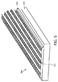
図3では、VCSEL12のアレイ11は、長手方向13のVCSEL12の3本のラインを有するとして示されている。しかしながら、光付与装置は、VCSELのより多くのライン又はより少ないラインも有し得る。その上、各ラインは、多少のVCSELを有する。図5は、対象物に光を付与するための光付与装置の図1乃至図3を参照して上述された他の要素と共に使われる光源304を模式的且つ例示的に示す。光源304は、5つの異なるサブグループを定めているVCSELの5本のラインを有するVCSEL311のアレイを有する。また、これら5つのサブグループは、制御ユニット9により互いに別々にアドレス指定できる。特に、異なるサブグループは、所望の光プロフィールを供給するために同じ及び/又は異なる強度、同じ及び/又は異なる波長を放射できる。
In FIG. 3, the
層320は、VCSELが取り付けられるサブマウントである。斯様なサブマウントは、例えば、銅、金、銀、パラジウム銀若しくは他の金属又は金属化合物でめっきされた、例えば、酸化アルミニウム、窒化アルミニウム、セラミック又は酸化ベリリウムから出来ている。代わりに、VCSELは、銅のサブマウントに直接取り付けられる。層321は、熱分散部材及びヒートシンクとして役立ち、例えばアルミニウム又は銅から作られている。
図1乃至図3を再度参照すると、制御ユニット9は、処理光2が検出された検知光5に依存して生成されるように光源4を制御する、特に制御ユニットは、処理光が、検出された検知光を表す光検出器により生成される信号の振幅に依存して生成されるように光源を制御するに適している。検出された検知光5は、対象物3の特性を表す。よって、処理光2が、検出された検知光5に依存して生成されるように光源4を制御することにより、対象物3の処理は、対象物3の特性に従って実施できる。
1 to 3 again, the
この実施例では、制御ユニット9は、検出された検知光5から対象物3の特性を決定し、処理光2が対象物3の決定された特性に依存して生成されるように、光源4を制御するのに適している。よって、処理光2の付与は、検出された検知光5に依存して直接実施でき、又は処理光2の付与は、検出された検知光5から決定される対象物の特性に依存して実施できる。
In this embodiment, the
制御ユニット9は、検出された検知光6からの検知光5の吸収を決定し、処理光2が決定された吸収に依存して生成されるように、光源4を制御するのに適していることが更に好ましい。これは、対象物3の吸収特性に依存して処理光2を制御可能にする。
The
制御ユニット9は、特に、検知光5の吸収に基づいて、対象物3の他の特性を決定するのに更に適している。例えば、皮膚タイプ、肌色及び/又は肌焼けの程度は、検出された検知光5に基づいて、特に、決定された吸収に基づいて決定できる。制御ユニット9は、好適には、対象物3の決定された特性、特に検知光5の決定された吸収と処理光2の特性との間の割り当てを定めている関数又はルックアップテーブルを有する。よって、対象物3の特性が決定された後、処理光2は制御ユニット9に保存されている処理光2の特性に従って生成できる。対象物3の決定された特性と処理光2の特性との間の対応する割当ては、較正測定により決定される。検出された検知光5に依存して対象物3の特性を決定するために、検出された検知光5と対象物3の特性との間の割当てを表す関数又はルックアップテーブルも使用でき、これらの割当ては較正測定によっても決定できる。例えば、検知光5は既知の特性を持つ対象物3に付与でき、検出された検知光5は、対応する割当てを生成するため対象物3の既知の特性に割り当てられる。検知光の吸収は、好適には以下の式に従って決定される。
ここで、xgは、光源と光検出器との間の距離を示し、αgは対象物の吸収係数を示し、効果的な吸収係数とみなすことができる。距離xgは既知であるので、光源により放射される強度I0及び光検出器により検出されるISを測定することにより、吸収係数αgが決定できる。制御ユニット9は、決定された吸収係数αgに依存して処理光2の生成を制御するために適合できる。光源が異なる位置に配置される光放射要素のアレイを有する場合、これらの光放射要素の平均位置が光源と光検出器との間の距離を決定するために使われ、光検出器が異なる位置に配置される幾つかの光検知素子を有する場合、これらの光検知素子の平均位置が光源と光検出器との間の距離を決定するために使われる。
The
Here, x g indicates the distance between the light source and the photodetector, and α g indicates the absorption coefficient of the object, which can be regarded as an effective absorption coefficient. The distance x g is known, by measuring the I S detected by the the intensity I 0 and the photodetector emitted by the light source, the absorption coefficient alpha g can be determined. The
制御ユニット9は、検知時間間隔で第1の検知光が第1のサブグループから放射され、第2の検知光が第2のサブグループから放射されるように光源4を制御するのに適合でき、第1の検知光及び第2の検知光は光検出器8により検出され、制御ユニット9は、検出された第1の検知信号及び検出された第2の検知信号に依存して光源4を制御するのに適している。特に、制御ユニット9は、処理光2が第1の検知光及び第2の検知光に依存して生成されるように光源4を制御するのに適している。
The
制御ユニット9は、好適には、処理光2が第1の検知光及び第2の検知光に依存して生成されるように、光源4を制御するのに適している。制御ユニット9は、光検出器8により生成される信号の振幅に依存して光源4を制御するのに適している、すなわち制御ユニット9は、検出された第1の検知光を表す第1の信号の第1の振幅及び検出された第2の検知光を表す第2の検知信号の第2の振幅に依存して光源を制御するのに適していることが更に好ましい。
The
これらの振幅は、対象物3の光特性、よって対象物3、特に皮膚への処理光2の浸透深度を示す。このように、処理光2が検出された第1の検知光及び検出された第2の検知光に依存して生成されるように、制御ユニット9を適合させることにより、処理光2、特に、強度及び波長は、対象物3への処理光2のそれぞれの浸透深度に適合できる。
These amplitudes indicate the optical properties of the
対象物3が人間又は動物の皮膚であることが更に好ましく、制御ユニット9は、表皮の決定された吸収及び真皮の決定された吸収の少なくとも1つに依存して、特に、表皮の決定された吸収係数及び真皮の決定された吸収係数の少なくとも1つに依存して処理光2が生成されるように光源4を制御するために、皮膚の表皮の第1及び第2の検知光の吸収と、検出された第1の検知光及び検出された第2の検知光から真皮の第1及び第2の検知光の吸収とを決定するのに適している。特に、制御ユニット9は、処理光2が表皮の決定された吸収に依存して生成されるように、光源4を制御するのに適している。
More preferably, the
光源4から光検出器8への途中で、検知光は、最初に表皮を通過し、真皮を通過し、最後に2回目の表皮通過を行う。表皮は、皮膚の一番上の層であり、一般に厚さわずか約0.1mmである。表皮は、光を吸収して、肌色及び肌焼けの程度を決定するメラニンを含む。表皮の光散乱は、比較的弱く、皮膚のこの層の小さな厚みのため、一般に無視できる。表皮の下に、一般に数ミリメートルの厚さを持つ真皮がある。真皮内で、光は、ヘモグロビン及び水により吸収される。更にまた、光は、真皮内で散乱され、皮膚の表面と平行に拡散し、光検出器8に到達する。光源4から光検出器8へ拡散する光は、式(1)に従って、光源4から光検出器8までのその強度の指数関数的な減衰により概略的に特徴づけられる。 On the way from the light source 4 to the photodetector 8, the detection light first passes through the epidermis, passes through the dermis, and finally passes through the epidermis for the second time. The epidermis is the top layer of the skin and is typically only about 0.1 mm thick. The epidermis contains melanin that absorbs light and determines the skin color and the degree of skin burn. The light scattering of the epidermis is relatively weak and is generally negligible due to the small thickness of this layer of skin. Below the epidermis is the dermis, which is generally a few millimeters thick. Within the dermis, light is absorbed by hemoglobin and water. Furthermore, the light is scattered in the dermis, diffuses parallel to the surface of the skin, and reaches the photodetector 8. The light diffusing from the light source 4 to the photodetector 8 is roughly characterized by an exponential decay of its intensity from the light source 4 to the photodetector 8 according to equation (1).
真皮内を第1の検知光が進む距離が、真皮内を第2の検知光が進む距離とは異なる場合、検出された第1の検知光を表す第1の信号の第1の振幅及び検出された第2の検知光を表す第2の信号の第2の振幅は、表皮の吸収係数αe及び真皮の吸収係数αdを決定可能にし、ここで、表皮内を検知光が進む距離xeが、約0.1mmであると知られている表皮の厚みの2倍であって、真皮内を検知光が進む距離xdが、光源4と光検出器8との間の距離により与えられると仮定される。光源4が異なる位置に配置される光放射要素のアレイ11を有する場合、距離xdは、好適には、光放射要素の平均位置と光検出器8の位置との間の距離であるとみなされる。光検出器8が、異なる位置に配置される幾つかの光検知素子を有する場合、これらの光検知素子の平均位置が、好適には、光源4と光検出器8との間の距離を決定するために使われる。このとき、肌色/タイプ及び肌焼けの程度は、表皮の吸収特性、すなわちαeから決定できる。
When the distance that the first detection light travels in the dermis is different from the distance that the second detection light travels in the dermis, the first amplitude and detection of the first signal that represents the detected first detection light The second amplitude of the second signal representing the generated second detection light makes it possible to determine the absorption coefficient α e of the epidermis and the absorption coefficient α d of the dermis, where the distance x the detection light travels in the epidermis e is twice the thickness of the epidermis, which is known to be about 0.1 mm, and the distance x d that the detection light travels in the dermis is given by the distance between the light source 4 and the photodetector 8 It is assumed that If the light source 4 has an
吸収係数αe及びαdは、効果的な吸収係数とみなすことができる。 The absorption coefficients α e and α d can be considered as effective absorption coefficients.
処理光2が検知光の吸収に依存して生成されるように、光源4を制御するために、制御ユニット9は、好適には、処理光2の特性を検知光の決定された吸収に割り当てる関数又はルックアップテーブルを有する。例えば、処理光2の強度及び/又は波長は、制御ユニット9により決定される吸収係数に割り当てられる。処理光2の特性と検知光の吸収との間の割当ては、較正測定により前もって決定できる。例えば、人間又は動物の皮膚に対して処理光2の最適化特性が既知である場合、検知光の吸収が皮膚に対して決定でき、決定された吸収は割当てを生成するため処理光2の最適化特性に割り当てられ、当該割り当ては制御ユニット9に保存できる。
In order to control the light source 4 so that the processing light 2 is generated in dependence on the absorption of the detection light, the
実施例では、VCSELのアレイは、アレイの中よりもアレイの端で大きいVCSELの空間密度を有する。VCSELのアレイが二次元アレイである場合、端はアレイの縁とみなされ、すなわちこの場合、VCSELの空間密度が、好適には、アレイの中よりアレイの縁で大きい。 In an embodiment, the array of VCSELs has a larger VCSEL spatial density at the edge of the array than in the array. If the array of VCSELs is a two-dimensional array, the edges are considered as the edges of the array, i.e., in this case, the spatial density of the VCSEL is preferably greater at the edge of the array than in the array.
処理光2が向かう対象物3の位置は、単一のVCSEL12により影響されず、幾つかの隣接するVCSELに影響される。VCSELのアレイ端部でVCSELが減少した数の隣を持つので、対象物3を処理するために使われる処理光2の強度は、より少ないVCSELが対象物3のそれぞれの位置に影響するので、VCSELのアレイ端部で減少する。VCSELのアレイ端部でVCSELの空間密度がアレイの中でより大きい場合、このより大きな空間密度は、VCSELのアレイ端部で低下した処理効果を打ち消すことができる。特に、VCSELのアレイ端部でのVCSELの空間密度は、VCSELのアレイ端部に配置される対象物3の位置が、VCSELのアレイに対してより中心に配置される対象物3の位置と同じ強度を受けるように適合される。
The position of the
対象物に光を付与する光付与方法の実施例は、図6に示されるフローチャートを参照して以下に説明されるだろう。 An embodiment of a light application method for applying light to an object will be described below with reference to the flowchart shown in FIG.
ステップ501では、制御ユニット9は、光源4が検知時間間隔で検知光5を生成するように光源4を制御する。検知光は、対象物3に入射する。
In
ステップ502では、検知光が対象物3を通って進んで、対象物3から離れた後、検知光5は光検出器8により検出される。
In
ステップ503では、制御ユニット9は、光源4が、検出された検知光に依存して処理時間間隔で処理光2を生成するように光源4を制御する。処理光は、対象物を処置する、特に、皮膚から毛髪を取り除くために対象物3に入射される。
In step 503, the
ステップ504では、光の付与を止めるべきか又は継続すべきか決定される。例えば、ユーザは、光付与装置のスイッチを切ることにより、光の付与を止めることができる。この場合、光付与方法は、ステップ505で終わる。例えば、光付与装置がスイッチオフされないので、光付与方法が続く場合、光付与方法はステップ501で継続する。
In
検知時間間隔は、好適には処理時間間隔より小さい。特に、検知時間間隔は、好適には、数百マイクロ秒の期間を持ち、例えば10ミリ秒未満、更に好ましくは1ミリ秒未満であるのに対し、処理時間間隔は、少なくとも数ミリ秒の期間を持ち、例えば、10ミリ秒より大きい期間、更に好ましくは100ミリ秒より大きく、更にもっと好ましくは1秒より大きい。 The detection time interval is preferably smaller than the processing time interval. In particular, the detection time interval preferably has a period of several hundred microseconds, for example less than 10 milliseconds, more preferably less than 1 millisecond, whereas the processing time interval is a period of at least several milliseconds. For example, greater than 10 milliseconds, more preferably greater than 100 milliseconds, and even more preferably greater than 1 second.
光付与装置は、好適には、輻射熱の脱毛及び皮膚治療アプリケーションのために使用され、VCSELのアレイは、理想的な波長範囲、平面源、電力節約及び信頼性のような複数の利点を提供する。加えて、VCSELのアレイは、光センサを集積する機会を提供し、これは皮膚からのフィードバックを可能にする。 The light applicator is preferably used for radiant heat epilation and skin treatment applications, and the array of VCSELs offers multiple advantages such as ideal wavelength range, planar source, power saving and reliability . In addition, an array of VCSELs provides an opportunity to integrate photosensors, which allows feedback from the skin.
単一のフォトダイオードは、レーザアレイと、皮膚を検知するための特別な電気的アドレス指定と組み合わせて使用できる。光付与装置及び光付与方法は、皮膚タイプ及び肌焼けの程度の信頼性が高いフィードバックを与える皮膚の赤外線の吸収のオンライン測定を可能にする。これは、完全な自己適応システムを可能にする。このように、特性決定ユニットは、好適には、検出された検知光に依存して皮膚タイプ及び/又は肌焼けの程度を決定するのに適合され、制御ユニットは、決定された皮膚タイプ及び/又は決定された肌焼けの程度に依存して処理光の生成を制御するのに適している。 A single photodiode can be used in combination with a laser array and special electrical addressing to detect the skin. The light imparting device and the light imparting method allow on-line measurement of the skin's infrared absorption giving reliable feedback on skin type and degree of skin burn. This allows for a complete self-adaptive system. Thus, the characterization unit is preferably adapted to determine the skin type and / or the degree of skin burns depending on the detected sensing light, and the control unit is adapted to determine the determined skin type and / or Or it is suitable for controlling the generation of the treatment light depending on the determined degree of skin burn.
検知光は、異なる波長を持つ光を放射できる。これは、皮膚への放射線の波長依存的な浸透を測定可能にする。放射線のこの波長依存的な浸透は、処理光の個々の波長が所望の浸透プロフィールを最適化しているレベルに調光されるように、処理光を生成するために使用できる。 The detection light can emit light having different wavelengths. This makes it possible to measure the wavelength-dependent penetration of radiation into the skin. This wavelength-dependent penetration of radiation can be used to generate processing light such that the individual wavelengths of processing light are dimmed to a level that optimizes the desired penetration profile.
VCSELを使用する代わりに、フラッシュランプ及びレーザーのような他の種類の光放射要素が使用できる。実施例では、処理光は、570―1200nmの範囲の波長、2―30J/cm2の範囲のエネルギー密度及び1―600ms以内のパルス持続期間を持つ。 Instead of using VCSELs, other types of light emitting elements such as flash lamps and lasers can be used. In an embodiment, the processed light has a wavelength in the range of 570-1200 nm, an energy density in the range of 2-30 J / cm 2 and a pulse duration within 1-600 ms.
光付与装置は、好適には、皮膚焼け及び痛みのような望ましくない副作用を最小限にしながら、特定の温度を超えて毛包を加熱するのに適している。処理光の理想的な波長及び最適量は、皮膚タイプ、肌焼けの程度等のような個別のパラメータに依存し、従って個々の設定を必要とする。これらの設定は、検出された検知光に依存して制御ユニット9により決定される。
The light imparting device is preferably suitable for heating the hair follicles above a certain temperature while minimizing undesirable side effects such as skin burns and pain. The ideal wavelength and optimum amount of processing light depends on individual parameters such as skin type, degree of skin burn, etc. and therefore requires individual settings. These settings are determined by the
光を対象物に付与するために、光源は、好適には、少ない痛み及び少ない副作用を持つ効率的な脱毛を実施するために、レーザーが、狭いスペクトル放射を提供し、パワー密度を正確に制御し、周囲皮膚の吸収に関して毛包のメラニンの最大の吸収を調整可能にするので、VCSELのためのアレイのようなレーザーを有する。 In order to impart light to the object, the light source preferably provides a narrow spectral emission and precise control of power density to perform efficient hair removal with less pain and fewer side effects. However, it has a laser like array for VCSELs, since it allows the maximum absorption of hair follicle melanin to be tuned with respect to absorption of the surrounding skin.
VCSELのアレイは、好適には数十Wに達して、必要なレーザーパワーを付与するための費用効果的な態様を表し、幾つかの利点を提供する。多くのVCSELの平面アレンジメントは、形状要因を適合可能にする。単一のVCSELは、好適には約100mWのパワーを持つ。従って、VCSELのアレイは、好適には、数百のVCSELを有する。図4に示される装置のような連続的に可動の手で持てるサイズの装置での脱毛手法のために、ラインに沿って、特に複数のラインに沿って、VCSELを配置することが好適である。更にまた、多くのVCSELの斯様な平面アレンジメントは、ヒートシンクを単純化する。 An array of VCSELs, preferably reaching tens of watts, represents a cost effective way to provide the necessary laser power and offers several advantages. Many VCSEL planar arrangements allow adaptation of form factors. A single VCSEL preferably has a power of about 100 mW. Thus, an array of VCSELs preferably has hundreds of VCSELs. For epilation techniques in a continuously movable hand-held device such as the device shown in FIG. 4, it is preferable to place the VCSEL along a line, particularly along multiple lines. . Furthermore, such a planar arrangement of many VCSELs simplifies the heat sink.
わずかに拡散的な円錐内のVCSELの放射特性は、皮膚まで数ミリメートルの距離に、レンズ又は反射器のような単に付加的な光学系なしに、これらVCSELを使用可能にする。これは、効果的な経費及び平坦なシステムを導く。その上、VCSELは、高いパワー変換効率及び低コストで600―1100nmの波長範囲内で作ることができる。 The radiating properties of VCSELs within a slightly diffusive cone allow these VCSELs to be used at distances of a few millimeters to the skin, and simply without additional optics such as lenses or reflectors. This leads to an effective cost and a flat system. In addition, VCSELs can be made in the 600-1100 nm wavelength range with high power conversion efficiency and low cost.
好適にはVCSELの平面アレンジメントであるVCSELのアレイは、好適には、長手方向である一つの長軸及び幅方向である一つの短軸を有する。皮膚の持続的処置のために、手で持てるサイズの装置は、好適には、短軸に沿って移動する。 An array of VCSELs, preferably a planar arrangement of VCSELs, preferably has one major axis that is the longitudinal direction and one minor axis that is the width direction. For sustained skin treatment, the hand-sized device preferably moves along the minor axis.
VCSELは、好適には、電子ドライバとみなすこともできる制御ユニットに個々のサブグループで電気的に接続される。サブグループは、例えば、同じ波長を持つVCSEL及び/又は例えば、アレイの一方の側若しくは反対側へ向かう特定の幾何学的な位置周辺のVCSELから成る。 The VCSEL is preferably electrically connected in individual subgroups to a control unit, which can also be regarded as an electronic driver. A subgroup consists of, for example, VCSELs with the same wavelength and / or, for example, VCSELs around a particular geometric location towards one side or the other side of the array.
光検出器は、好適には、フォトダイオードのような電気光学センサであり、個々のサブグループのVCSELまでの平均距離が異なる位置に配置される。1つのサブグループの検知光は、皮膚を透過して、全方向に散乱し、従って、皮膚を通って例えば光検出器の方へ進み、皮膚を離れて光検出器に当たる。異なるサブグループからの検知光は、光検出器に向かって皮膚の異なる距離を進まなければならない。従って、信号強度は、皮膚の光特性、特に吸収及び散乱に関する情報を含む。 The photodetector is preferably an electro-optic sensor such as a photodiode and is located at a position where the average distances to the VCSELs of the individual subgroups are different. The detection light of one subgroup penetrates the skin and scatters in all directions, so it travels through the skin, for example, towards the photodetector and leaves the skin and strikes the photodetector. Sensing light from different subgroups must travel different distances of the skin towards the photodetector. The signal intensity thus contains information about the light properties of the skin, in particular absorption and scattering.
光検出器は、好適には、光検出器の隣のはっきり定められた皮膚領域だけから、検知光を受信する。これは、光検出器により検出される検知光が皮膚を通過して現実に進んでいることを確実にする。これは、好適には漏斗形状を持ち、好適には少なくとも検知時間間隔の間、皮膚と接触している、光検出器8周辺の開口部10により実現される。
The photodetector preferably receives sensing light only from a well-defined skin area next to the photodetector. This ensures that the detection light detected by the photodetector is actually traveling through the skin. This is achieved by an
好適には、検知時間間隔の間に、1つのサブグループだけが一度に動作される。これにより、光検出器により受信される検知光がどのサブグループから放射されるかを知ることができる。光検出器により生成される結果として生じる信号は、測定時に動作された、それぞれのサブグループと相関付けられて記録できる。結果は制御ユニットに格納され、処置パラメータがこれらの測定に関係して選ばれ、すなわち制御は、好適には、処理光の設定が、検出された検知光に依存して格納されているルックアップテーブルを有する。これは、光検出器がそれぞれの検知光を検出する場合、検出された検知光と、対象物を処理するために使用されるべき処理光の設定との間の割当てが格納されることを意味する。これらの割当ては、例えば、対象物の処理が光検出器により検出される検知光に依存して最適化されるように、較正測定により決定できる。 Preferably, only one subgroup is operated at a time during the detection time interval. Thereby, it can be known from which subgroup the detection light received by the photodetector is emitted. The resulting signal generated by the photodetector can be recorded in correlation with each subgroup operated during the measurement. The result is stored in the control unit and the treatment parameters are selected in relation to these measurements, i.e. the control is preferably a lookup in which the setting of the processing light is stored depending on the detected light detected. Has a table. This means that when the light detector detects the respective detection light, the assignment between the detected detection light and the setting of the processing light to be used for processing the object is stored. To do. These assignments can be determined by calibration measurements, for example, so that the processing of the object is optimized depending on the sensed light detected by the photodetector.
図3に示されるVCSEL12のアレイ11は、6つのサブグループ111、112、113、121、122、123を有する。しかしながら、制御ユニット9は、これら幾つかのサブグループが単一のサブグループとみなすことができるように、これらのサブグループの幾つかが、同様に制御されるようにも適合できる。例えば、図3に示されるアレイ11が、2つのサブグループ、サブグループ111、112、113からなる第1のサブグループ及びサブグループ121、122、123からなる第2のサブグループから成るとみなすことができるように、3つのサブグループ111、112、113は同様に制御でき、3つのサブグループ121、122、123は同様に制御できる。例えば、第1のサブグループは、検知時間間隔中の第1の時間間隔の間に、第1のサブグループだけが皮膚を通って進み、光検出器により最後に検出される検知光を放射し、同じ検知時間間隔中の第2の時間間隔の間に、第2のサブグループが対象物に検知光を放射して、当該検知光は、対象物を通って進み、光検出器により最後に検出されるように制御できる。よって、このようにして、第1の検知光は第1の時間間隔の間に検出され、第2の検知光は第2の時間間隔の間に検出される。
The
異なるサブグループが、好適には、異なるサブグループが異なってアドレス指定できるように、制御ユニット9に接続されているので、異なるサブグループは、異なる波長を持つ検知光及び/又は処理光を放射できる。好適には、処理光及び/又は検知光のパワーレベル、すなわち強度は、それぞれの皮膚タイプの吸収特性に依存する、それぞれの波長の吸収特性に依存して選択される。しかしながら、特定の所望の照射プロフィールを得るために同じ波長で動作する場合であっても、異なるサブグループのVCSELは、異なるパワーレベルにも設定できる。例えば、同じ波長で動作する場合であっても、サブグループ121、123は、サブグループ122とは異なるパワーレベルに設定できる。これは、側部への熱放散がVCSELのアレイの中心に対するより強いので、特に有利である。
Different subgroups are preferably connected to the
動きの方向が、例えば、速度測定ユニット15により実施される速度測定から既知である場合、図3に示される3本のラインは、光源4が皮膚のポイント間を移動する間、時間とともに好ましい温度勾配を得るために異なるパワーレベルで動作できる。
If the direction of movement is known, for example from the speed measurement performed by the
検出された検知光は、よって特に、検出された検知光に依存して決定される対象物の特性は、強度、波長、処理光が対象物に繰り返し且つ途切れ途切れに付与される場合の繰り返し周波数、処理光がパルス化されて付与される場合のパルス期間等の処理光の設定のうちの少なくとも1つを決定するために使用できる。 The detected light detected, and in particular the characteristics of the object determined in dependence on the detected light detected, are the repetition frequency when the intensity, wavelength, and processed light are repeatedly applied to the object. , Can be used to determine at least one of the settings of the processing light, such as the pulse duration when the processing light is pulsed and applied.
上述された実施例では、光源は、好適には、VCSELを有するにもかかわらず、他の実施例では、光源は他の光放射要素を有することもできる。例えば、光源は、発光ダイオード、有機ダイオード及び/又はレーザダイオードのような半導体光源を有することもできる。好適なレーザダイオードは、VCSELである。しかしながら、また、エッジ発光レーザダイオードが、光源の光放射要素として使用できる。 In the embodiments described above, the light source preferably comprises a VCSEL, but in other embodiments the light source may comprise other light emitting elements. For example, the light source may comprise a semiconductor light source such as a light emitting diode, an organic diode and / or a laser diode. A suitable laser diode is a VCSEL. However, edge emitting laser diodes can also be used as the light emitting element of the light source.
上述された光付与装置及び光付与方法が、好適には、人の皮膚から毛髪を取り除くのに適しているにもかかわらず、光付与装置は、他の種類の対象物についての他の種類の処理、例えば、技術的な対象物の表面の処理を実施するためにも使用できる。 Although the light application device and the light application method described above are preferably suitable for removing hair from a human skin, the light application device is suitable for other types of objects. It can also be used to carry out a treatment, for example a treatment of the surface of a technical object.
開示された実施例に対する他の変形例は、図面、明細書及び添付の特許請求の範囲の学習から、請求された本発明を実施する際の当業者により理解され、遂行できる。 Other variations to the disclosed embodiments can be understood and carried out by those skilled in the art in practicing the claimed invention, from a study of the drawings, the specification, and the appended claims.
請求項では、用語「を有する」は、他の要素又はステップを除外しないし、不定冠詞「a」又は「an」は、複数を除外しない。 In the claims, the term “comprising” does not exclude other elements or steps, and the indefinite article “a” or “an” does not exclude a plurality.
単一のユニット又は装置は、請求項に引用される幾つかのアイテムの機能を満たしてもよい。特定の手法が互いに異なる従属請求項において引用されているという単なる事実は、これらの手法の組合せが効果的に使用できないことを示さない。 A single unit or device may fulfill the functions of several items recited in the claims. The mere fact that certain techniques are recited in mutually different dependent claims does not indicate that a combination of these techniques cannot be used effectively.
検出された検知光に直接依存する、若しくは対象物の決定された特性に依存する処理光の設定の決定、又は、1つ若しくは複数のユニット又は装置により実施される対象物の特性の決定のような決定は、他の任意の数のユニット又は装置によっても実施できる。光付与方法に従う光付与装置の決定及び/又は制御は、コンピュータプログラムのプログラムコード手段として及び/又は専用ハードウエアとして実行できる。 Such as determining the setting of the processing light that depends directly on the detected sensing light or on the determined characteristics of the object, or the determination of the characteristics of the object carried out by one or more units or devices Such a determination can also be made by any other number of units or devices. The determination and / or control of the light application device according to the light application method can be performed as program code means of a computer program and / or as dedicated hardware.
コンピュータプログラムは、他のハードウェアの一部若しくは共に光記憶媒体又は半導体媒体のような適切な媒体に格納されて/配布されてもよいし、インターネット、又は他の有線若しくは無線通信システムを介してのような他の形式でも配布されてもよい。 The computer program may be stored / distributed on a suitable medium such as an optical storage medium or a semiconductor medium, or a part of other hardware, or via the Internet or other wired or wireless communication system. It may be distributed in other formats such as
請求項内の任意の参照符号は、範囲を制限するものとして解釈されてはならない。 Any reference signs in the claims should not be construed as limiting the scope.
Claims (11)
Applications Claiming Priority (3)
| Application Number | Priority Date | Filing Date | Title |
|---|---|---|---|
| EP09165868 | 2009-07-20 | ||
| EP09165868.2 | 2009-07-20 | ||
| PCT/IB2010/053122 WO2011010239A1 (en) | 2009-07-20 | 2010-07-08 | Light application apparatus for applying light to an object |
Publications (3)
| Publication Number | Publication Date |
|---|---|
| JP2012533386A JP2012533386A (en) | 2012-12-27 |
| JP2012533386A5 JP2012533386A5 (en) | 2013-08-22 |
| JP5715128B2 true JP5715128B2 (en) | 2015-05-07 |
Family
ID=42670308
Family Applications (1)
| Application Number | Title | Priority Date | Filing Date |
|---|---|---|---|
| JP2012521126A Active JP5715128B2 (en) | 2009-07-20 | 2010-07-08 | Light imparting device for imparting light to an object |
Country Status (6)
| Country | Link |
|---|---|
| US (2) | US9375281B2 (en) |
| EP (1) | EP2456382B1 (en) |
| JP (1) | JP5715128B2 (en) |
| KR (1) | KR101727095B1 (en) |
| CN (1) | CN102470012B (en) |
| WO (1) | WO2011010239A1 (en) |
Cited By (4)
| Publication number | Priority date | Publication date | Assignee | Title |
|---|---|---|---|---|
| WO2022168494A1 (en) | 2021-02-05 | 2022-08-11 | パナソニックIpマネジメント株式会社 | Light irradiation hair removal device |
| WO2022168493A1 (en) | 2021-02-05 | 2022-08-11 | パナソニックIpマネジメント株式会社 | Light irradiation hair removal device |
| WO2022168489A1 (en) | 2021-02-05 | 2022-08-11 | パナソニックIpマネジメント株式会社 | Light-irradiation-type depilation device |
| WO2022168492A1 (en) | 2021-02-05 | 2022-08-11 | パナソニックIpマネジメント株式会社 | Light irradiation hair removal device |
Families Citing this family (30)
| Publication number | Priority date | Publication date | Assignee | Title |
|---|---|---|---|---|
| US8048089B2 (en) | 2005-12-30 | 2011-11-01 | Edge Systems Corporation | Apparatus and methods for treating the skin |
| WO2009088884A1 (en) | 2008-01-04 | 2009-07-16 | Edge Systems Corporation | Apparatus and method for treating the skin |
| CN103025380A (en) * | 2010-08-11 | 2013-04-03 | 皇家飞利浦电子股份有限公司 | Phototherapy method and device |
| WO2012023086A1 (en) * | 2010-08-17 | 2012-02-23 | Koninklijke Philips Electronics N.V. | Flexible light therapy device, a plaster and a bandage |
| US9414888B2 (en) | 2011-02-03 | 2016-08-16 | Tria Beauty, Inc. | Devices and methods for radiation-based dermatological treatments |
| US9005262B2 (en) * | 2011-02-03 | 2015-04-14 | Tria Beauty, Inc. | Radiation-based dermatological devices and methods |
| US11406448B2 (en) | 2011-02-03 | 2022-08-09 | Channel Investments, Llc | Devices and methods for radiation-based dermatological treatments |
| US8679102B2 (en) | 2011-02-03 | 2014-03-25 | Tria Beauty, Inc. | Devices and methods for radiation-based dermatological treatments |
| US9789332B2 (en) | 2011-02-03 | 2017-10-17 | Tria Beauty, Inc. | Devices and methods for radiation-based dermatological treatments |
| US8685008B2 (en) | 2011-02-03 | 2014-04-01 | Tria Beauty, Inc. | Devices and methods for radiation-based dermatological treatments |
| US9173708B2 (en) * | 2011-03-30 | 2015-11-03 | Tria Beauty, Inc. | Dermatological treatment device with one or more laser diode bar |
| KR101964387B1 (en) * | 2012-03-21 | 2019-04-01 | 트리아 뷰티, 인코포레이티드 | Dermatological treatment device with one or more vertical cavity surface emitting laser(vcsel) |
| US20140135804A1 (en) | 2012-11-15 | 2014-05-15 | Ethicon Endo-Surgery, Inc. | Ultrasonic and electrosurgical devices |
| EP3437575B1 (en) | 2013-03-15 | 2021-04-21 | Edge Systems LLC | Devices and systems for treating the skin |
| EP3065918B2 (en) | 2013-11-06 | 2021-09-29 | Koninklijke Philips N.V. | A system and a method for treating a part of a body |
| GB2526764B (en) * | 2013-12-04 | 2020-10-07 | Ipulse Ltd | Skin treatment apparatus utilising intense pulsed light (IPL) |
| EP4324414A2 (en) | 2014-12-23 | 2024-02-21 | HydraFacial LLC | Devices and methods for treating the skin using a rollerball or a wicking member |
| ES2893295T3 (en) | 2016-02-02 | 2022-02-08 | Braun Gmbh | skin treatment device |
| EP3202359B1 (en) | 2016-02-02 | 2021-08-25 | Braun GmbH | Skin treatment device |
| AU2017217247A1 (en) * | 2016-02-10 | 2018-09-27 | Helium 3 Resources Pty Ltd | A therapeutic method and device therefor |
| CN109310875A (en) * | 2016-06-15 | 2019-02-05 | 香港康美有限公司 | Go the device and method of hair removal |
| JP2019535427A (en) * | 2016-11-22 | 2019-12-12 | ドミニオン エスセティック テクノロジーズ インコーポレイテッドDominion Aesthetic Technologies, Inc. | Aesthetic treatment system and method |
| IT201700062592A1 (en) * | 2017-06-08 | 2018-12-08 | K Laser D O O | Apparatus for scanning laser therapy. |
| EP3437696B1 (en) * | 2017-08-01 | 2021-02-24 | Braun GmbH | Light-based epilation device and method of cosmetic hair removal |
| EP3453280A1 (en) * | 2017-09-10 | 2019-03-13 | Koninklijke Philips N.V. | Hair styling device |
| ES2825030T3 (en) * | 2018-01-31 | 2021-05-14 | Braun Gmbh | Device for the treatment of skin or hair and method of making the same |
| DE102018118912A1 (en) * | 2018-08-03 | 2020-02-06 | Osram Opto Semiconductors Gmbh | Irradiation device and method for operating an irradiation device |
| WO2020174547A1 (en) * | 2019-02-25 | 2020-09-03 | 大塚電子株式会社 | Photodynamic therapy device |
| CN113100925B (en) * | 2021-04-01 | 2023-12-08 | 优秀新品(深圳)科技有限公司 | Dehairing instrument and control method thereof |
| USD1016615S1 (en) | 2021-09-10 | 2024-03-05 | Hydrafacial Llc | Container for a skin treatment device |
Family Cites Families (17)
| Publication number | Priority date | Publication date | Assignee | Title |
|---|---|---|---|---|
| US5405368A (en) | 1992-10-20 | 1995-04-11 | Esc Inc. | Method and apparatus for therapeutic electromagnetic treatment |
| US6015404A (en) | 1996-12-02 | 2000-01-18 | Palomar Medical Technologies, Inc. | Laser dermatology with feedback control |
| US6168590B1 (en) | 1997-08-12 | 2001-01-02 | Y-Beam Technologies, Inc. | Method for permanent hair removal |
| US6074382A (en) | 1997-08-29 | 2000-06-13 | Asah Medico A/S | Apparatus for tissue treatment |
| EP1279374A1 (en) * | 1999-02-26 | 2003-01-29 | Nidek Co., Ltd | Laser depilation apparatus |
| JP3921306B2 (en) * | 1999-02-26 | 2007-05-30 | 株式会社ニデック | Laser therapy device |
| US6190377B1 (en) * | 1999-05-05 | 2001-02-20 | James A. Kuzdrall | Method and apparatus for predictive beam energy control in laser surgery |
| GB2372096A (en) | 2000-09-27 | 2002-08-14 | Litron Optical Ltd | Apparatus for determining skin types by detecting the light emitted to and then reflected from skin |
| CN1463188A (en) | 2001-04-20 | 2003-12-24 | 皇家菲利浦电子有限公司 | Skin treating device with protection against rediation pulse overdose |
| DE10120787A1 (en) | 2001-04-25 | 2003-01-09 | Foerderung Von Medizin Bio Und | Remission-controlled device with laser handpiece for sensor-controlled selective laser therapy of blood vessels and skin tissues has multiple-sensor system e.g. using near infrared or visible radiation |
| US20070213696A1 (en) * | 2006-03-10 | 2007-09-13 | Palomar Medical Technologies, Inc. | Photocosmetic device |
| CA2566547A1 (en) | 2003-05-14 | 2004-11-25 | Spectracure Ab | System and method for therapy and diagnosis comprising in combination non-mechanical and mechanical distributors for distribution of radiation |
| US7736382B2 (en) * | 2005-09-09 | 2010-06-15 | Lockheed Martin Corporation | Apparatus for optical stimulation of nerves and other animal tissue |
| JP4668102B2 (en) | 2006-03-22 | 2011-04-13 | 古河電気工業株式会社 | Beauty laser equipment |
| HRP20060149B1 (en) * | 2006-04-19 | 2008-11-30 | Institut "Ruđer Bošković" | Intelligent sequential illuminator photodynamic therapy |
| US20080154247A1 (en) | 2006-12-20 | 2008-06-26 | Reliant Technologies, Inc. | Apparatus and method for hair removal and follicle devitalization |
| DE102008048409A1 (en) * | 2008-09-23 | 2010-03-25 | Megasun Invest Ag | Method and device for hair removal |
-
2010
- 2010-07-08 JP JP2012521126A patent/JP5715128B2/en active Active
- 2010-07-08 KR KR1020127004191A patent/KR101727095B1/en active IP Right Grant
- 2010-07-08 WO PCT/IB2010/053122 patent/WO2011010239A1/en active Application Filing
- 2010-07-08 US US13/384,803 patent/US9375281B2/en active Active
- 2010-07-08 EP EP10740347.9A patent/EP2456382B1/en active Active
- 2010-07-08 CN CN201080032994.5A patent/CN102470012B/en active Active
-
2016
- 2016-06-02 US US15/171,450 patent/US20160270851A1/en not_active Abandoned
Cited By (4)
| Publication number | Priority date | Publication date | Assignee | Title |
|---|---|---|---|---|
| WO2022168494A1 (en) | 2021-02-05 | 2022-08-11 | パナソニックIpマネジメント株式会社 | Light irradiation hair removal device |
| WO2022168493A1 (en) | 2021-02-05 | 2022-08-11 | パナソニックIpマネジメント株式会社 | Light irradiation hair removal device |
| WO2022168489A1 (en) | 2021-02-05 | 2022-08-11 | パナソニックIpマネジメント株式会社 | Light-irradiation-type depilation device |
| WO2022168492A1 (en) | 2021-02-05 | 2022-08-11 | パナソニックIpマネジメント株式会社 | Light irradiation hair removal device |
Also Published As
| Publication number | Publication date |
|---|---|
| KR20120049274A (en) | 2012-05-16 |
| CN102470012B (en) | 2015-03-11 |
| EP2456382B1 (en) | 2015-02-25 |
| JP2012533386A (en) | 2012-12-27 |
| EP2456382A1 (en) | 2012-05-30 |
| CN102470012A (en) | 2012-05-23 |
| US20120116373A1 (en) | 2012-05-10 |
| US9375281B2 (en) | 2016-06-28 |
| US20160270851A1 (en) | 2016-09-22 |
| WO2011010239A1 (en) | 2011-01-27 |
| KR101727095B1 (en) | 2017-05-02 |
Similar Documents
| Publication | Publication Date | Title |
|---|---|---|
| JP5715128B2 (en) | Light imparting device for imparting light to an object | |
| JP7348155B2 (en) | hair removal device | |
| KR102142266B1 (en) | Skin treatment device | |
| US20170172660A1 (en) | Irradiation unit for providing radiation pulses for irradiating a skin surface and method for operating an irradiation unit | |
| JP6959717B2 (en) | Light-based hair removal device and cosmetic hair removal method | |
| US20110137303A1 (en) | Self-contained handpiece and method for optical tissue surface treatment | |
| CN215136076U (en) | Laser beauty equipment | |
| RU2734471C1 (en) | Hair styling device | |
| RU2733631C1 (en) | Hair styling device | |
| CN113058164A (en) | Laser beauty equipment and control method thereof |
Legal Events
| Date | Code | Title | Description |
|---|---|---|---|
| A521 | Request for written amendment filed |
Free format text: JAPANESE INTERMEDIATE CODE: A523 Effective date: 20130703 |
|
| A621 | Written request for application examination |
Free format text: JAPANESE INTERMEDIATE CODE: A621 Effective date: 20130703 |
|
| RD02 | Notification of acceptance of power of attorney |
Free format text: JAPANESE INTERMEDIATE CODE: A7422 Effective date: 20130703 |
|
| A977 | Report on retrieval |
Free format text: JAPANESE INTERMEDIATE CODE: A971007 Effective date: 20140326 |
|
| A131 | Notification of reasons for refusal |
Free format text: JAPANESE INTERMEDIATE CODE: A131 Effective date: 20140408 |
|
| A521 | Request for written amendment filed |
Free format text: JAPANESE INTERMEDIATE CODE: A523 Effective date: 20140704 |
|
| TRDD | Decision of grant or rejection written | ||
| A01 | Written decision to grant a patent or to grant a registration (utility model) |
Free format text: JAPANESE INTERMEDIATE CODE: A01 Effective date: 20150216 |
|
| A61 | First payment of annual fees (during grant procedure) |
Free format text: JAPANESE INTERMEDIATE CODE: A61 Effective date: 20150312 |
|
| R150 | Certificate of patent or registration of utility model |
Ref document number: 5715128 Country of ref document: JP Free format text: JAPANESE INTERMEDIATE CODE: R150 |
|
| R250 | Receipt of annual fees |
Free format text: JAPANESE INTERMEDIATE CODE: R250 |
|
| R250 | Receipt of annual fees |
Free format text: JAPANESE INTERMEDIATE CODE: R250 |
|
| R250 | Receipt of annual fees |
Free format text: JAPANESE INTERMEDIATE CODE: R250 |
|
| R250 | Receipt of annual fees |
Free format text: JAPANESE INTERMEDIATE CODE: R250 |
|
| R250 | Receipt of annual fees |
Free format text: JAPANESE INTERMEDIATE CODE: R250 |
|
| R250 | Receipt of annual fees |
Free format text: JAPANESE INTERMEDIATE CODE: R250 |
|
| R250 | Receipt of annual fees |
Free format text: JAPANESE INTERMEDIATE CODE: R250 |