JP5710473B2 - Control of the positional relationship between the sample collection device and the surface to be analyzed in the sampling procedure using a laser sensor - Google Patents
Control of the positional relationship between the sample collection device and the surface to be analyzed in the sampling procedure using a laser sensor Download PDFInfo
- Publication number
- JP5710473B2 JP5710473B2 JP2011516271A JP2011516271A JP5710473B2 JP 5710473 B2 JP5710473 B2 JP 5710473B2 JP 2011516271 A JP2011516271 A JP 2011516271A JP 2011516271 A JP2011516271 A JP 2011516271A JP 5710473 B2 JP5710473 B2 JP 5710473B2
- Authority
- JP
- Japan
- Prior art keywords
- laser sensor
- distance
- collection device
- actual
- sample
- Prior art date
- Legal status (The legal status is an assumption and is not a legal conclusion. Google has not performed a legal analysis and makes no representation as to the accuracy of the status listed.)
- Active
Links
- 238000000034 method Methods 0.000 title claims description 54
- 238000005070 sampling Methods 0.000 title claims description 34
- 230000008569 process Effects 0.000 claims description 24
- 238000013459 approach Methods 0.000 claims description 7
- 239000000463 material Substances 0.000 claims description 7
- 238000004458 analytical method Methods 0.000 claims description 6
- 238000004364 calculation method Methods 0.000 claims description 4
- 238000012935 Averaging Methods 0.000 claims description 2
- 230000000977 initiatory effect Effects 0.000 claims description 2
- 230000004044 response Effects 0.000 claims description 2
- 239000000523 sample Substances 0.000 description 83
- 238000000688 desorption electrospray ionisation Methods 0.000 description 6
- 238000005259 measurement Methods 0.000 description 6
- 238000002360 preparation method Methods 0.000 description 5
- 238000001396 desorption atmospheric pressure chemical ionisation Methods 0.000 description 4
- 230000008901 benefit Effects 0.000 description 3
- 238000003795 desorption Methods 0.000 description 3
- 239000007921 spray Substances 0.000 description 3
- 239000003153 chemical reaction reagent Substances 0.000 description 2
- 238000010586 diagram Methods 0.000 description 2
- 150000002500 ions Chemical class 0.000 description 2
- 238000004949 mass spectrometry Methods 0.000 description 2
- 239000011159 matrix material Substances 0.000 description 2
- 238000012544 monitoring process Methods 0.000 description 2
- 230000002441 reversible effect Effects 0.000 description 2
- 238000000926 separation method Methods 0.000 description 2
- 238000004809 thin layer chromatography Methods 0.000 description 2
- 230000008859 change Effects 0.000 description 1
- 238000010276 construction Methods 0.000 description 1
- 238000013480 data collection Methods 0.000 description 1
- 238000001514 detection method Methods 0.000 description 1
- 238000011161 development Methods 0.000 description 1
- 238000005516 engineering process Methods 0.000 description 1
- 230000006870 function Effects 0.000 description 1
- 239000007788 liquid Substances 0.000 description 1
- 238000012986 modification Methods 0.000 description 1
- 230000004048 modification Effects 0.000 description 1
- 230000000737 periodic effect Effects 0.000 description 1
- 239000000126 substance Substances 0.000 description 1
- 238000006467 substitution reaction Methods 0.000 description 1
- 239000000758 substrate Substances 0.000 description 1
Images


Classifications
-
- H—ELECTRICITY
- H01—ELECTRIC ELEMENTS
- H01J—ELECTRIC DISCHARGE TUBES OR DISCHARGE LAMPS
- H01J49/00—Particle spectrometers or separator tubes
- H01J49/02—Details
- H01J49/04—Arrangements for introducing or extracting samples to be analysed, e.g. vacuum locks; Arrangements for external adjustment of electron- or ion-optical components
- H01J49/0459—Arrangements for introducing or extracting samples to be analysed, e.g. vacuum locks; Arrangements for external adjustment of electron- or ion-optical components for solid samples
Landscapes
- Chemical & Material Sciences (AREA)
- Analytical Chemistry (AREA)
- Sampling And Sample Adjustment (AREA)
- Length Measuring Devices By Optical Means (AREA)
- Electron Tubes For Measurement (AREA)
Description
本発明は、一般にサンプリング手段および方法に関し、より詳細には被分析表面上の領域または場所から試料を得るための手段および方法に関する。 The present invention relates generally to sampling means and methods, and more particularly to means and methods for obtaining a sample from a region or location on an analyzed surface.
本発明は、米国エネルギー省からUT−Battelle,LLCに認められた契約番号DE−AC05−00OR22725による政府支援で行われ、政府は本発明に対して特定の権利を有する。 This invention is made with government support under the contract number DE-AC05-00OR22725 approved by UT-Battelle, LLC from the US Department of Energy and the government has certain rights to the invention.
本発明が関係するサンプリング収集技術は、分析のために表面の質量(例えば、イオン)を収集する目的で、分析またはサンプリングされる表面の比較的近くに収集機器や他の試料収集装置を位置決めすることを必要とする。そのような収集技術の一例は、脱離エレクトロスプレイイオン化(DESI)質量分析法と関連して使用されるが、脱離大気圧化学イオン化(DAPCI)やマトリックス支援レーザ脱離/イオン化(MALDI)などを含むような他の技術にも当てはまる。そのようなどの技術でも最適な収集結果を得るために、収集機器がサンプリングされる表面から所定の(すなわち、望ましい)距離に維持され、それにより後で分析されたときに収集結果が誤って解釈される可能性を少なくすることが望ましい。 Sampling and collection techniques to which the present invention pertains position collection equipment and other sample collection devices relatively close to the surface to be analyzed or sampled for the purpose of collecting surface mass (eg, ions) for analysis. I need that. An example of such a collection technique is used in conjunction with desorption electrospray ionization (DESI) mass spectrometry, such as desorption atmospheric pressure chemical ionization (DAPCI) and matrix-assisted laser desorption / ionization (MALDI). This also applies to other technologies such as To obtain optimal collection results with any such technique, the collection device is maintained at a predetermined (ie, desirable) distance from the surface to be sampled so that the collection results are misinterpreted when analyzed later. It is desirable to reduce the possibility of being done.
さらに、噴霧柱(スプレイ・プルーム)内で試料収集プロセス中にサンプリング表面に試薬を送出する自己吸気式放射器を必要とするいくつかの試料収集プロセスが存在する。そのような放射器(エミッタ)は、一般に、噴霧柱がサンプリング表面に向かって所定の(すなわち、固定された)入射角で導かれるように収集機器または装置に対して所定の位置に固定され、それにより、送出された噴霧柱が、サンプリング表面の所定の位置に当たり、それによりサンプリング表面の物質を収集機器の方に移動させることができる。換言すると、放射器と収集機器と被分析表面との間に望ましい空間割り当てが存在し、位置決めされるべき位置(例えば、所定の平面内)に表面が正確に位置決めされないと、満足な収集結果が得られない可能性が高い。 In addition, there are several sample collection processes that require a self-aspirating radiator to deliver reagents to the sampling surface during the sample collection process within the spray plume. Such emitters (emitters) are generally fixed in place relative to a collection device or device such that the spray column is directed at a predetermined (ie, fixed) angle of incidence toward the sampling surface, Thereby, the delivered spray column strikes a predetermined position on the sampling surface, thereby allowing the material on the sampling surface to move towards the collection device. In other words, if there is a desired spatial allocation between the radiator, the collection device and the surface to be analyzed and the surface is not accurately positioned at the position to be positioned (eg, in a predetermined plane), a satisfactory collection result will be obtained. There is a high possibility that it will not be obtained.
オペレータが、試料収集プロセス中に試料収集機器と表面との距離を手動調整する必要をなくすために、試料収集プロセス中に試料収集機器−表面間距離を正確に制御するシステムおよび方法を提供することが望ましい。 To provide a system and method for accurately controlling the distance between a sample collection device and a surface during the sample collection process so that an operator does not need to manually adjust the distance between the sample collection device and the surface during the sample collection process Is desirable.
従って、本発明の目的は、レーザ・センサを利用してサンプリング手順における実際の収集機器−表面間距離を監視する機器によって、試料収集機器(または装置)と分析(またはサンプリング)される表面との間の距離を自動的に制御するシステムおよび方法を提供することである。 Accordingly, it is an object of the present invention to connect a sample collection device (or apparatus) to a surface to be analyzed (or sampled) by means of a laser sensor that monitors the actual collection device-surface distance in a sampling procedure. It is to provide a system and method for automatically controlling the distance between.
本発明の別の目的は、収集機器−表面間距離がサンプリング手順中ずっと連続的に監視され、必要に応じて収集機器−表面間距離が最適間隔で維持されるように調整されるシステムおよび方法を提供することである。 Another object of the present invention is a system and method in which the collection device-surface distance is continuously monitored throughout the sampling procedure and is adjusted as necessary to maintain the collection device-surface distance at an optimal spacing. Is to provide.
本発明のさらに別の目的は、試料収集プロセスの結果が分析されるときに誤って解釈される可能性を減少させるシステムを提供することである。 Yet another object of the present invention is to provide a system that reduces the possibility of misinterpretation when the results of a sample collection process are analyzed.
本発明の更に他の目的は、試料に対して所定の角度で向けられた放射器を利用する試料収集操作と関連して使用されるときに、試料収集プロセス中に放射器と収集機器と被分析表面との間の適切な空間割り当てを維持するのに役立つシステムを提供することである。 Yet another object of the present invention is that when used in connection with a sample collection operation that utilizes a radiator oriented at a predetermined angle with respect to the sample, the radiator, the collection device, and the substrate during the sample collection process. It is to provide a system that helps to maintain proper space allocation between the analytical surfaces.
本発明のさらに別の目的は、構造が複雑でないにも関わらず動作が有効なシステムを提供することである。 Yet another object of the present invention is to provide a system that is effective in operation despite its uncomplicated structure.
本発明は、被分析表面から試料を収集するためのサンプリング・システムおよび方法にある。 The present invention resides in a sampling system and method for collecting a sample from an analyzed surface.
サンプリング・システムは、被分析表面から試料を収集する試料収集機器と、収集機器と表面を互いに近づけ遠ざけるための手段とを含み、収集機器と表面との間には試料収集に望ましい位置関係が存在する。システムは、また、レーザ・センサと表面との間の実際の距離に対応する信号を生成するために、収集機器に対して固定された位置関係で配置されたレーザ・センサを含む距離測定手段を含み、収集機器と表面とが試料収集に望ましい位置関係で配置されたときにレーザ・センサと表面との間にターゲット距離が存在する。 The sampling system includes a sample collection device that collects the sample from the surface to be analyzed, and a means for moving the collection device and the surface closer together, and there is a desired positional relationship between the collection device and the surface for sample collection. To do. The system also includes distance measuring means including a laser sensor disposed in a fixed positional relationship with respect to the collection device to generate a signal corresponding to the actual distance between the laser sensor and the surface. In addition, there is a target distance between the laser sensor and the surface when the collection device and the surface are placed in the desired positional relationship for sample collection.
更に、システムは、レーザ・センサと表面の間の実際の距離に対応する信号を受け取るための手段と、レーザ・センサと表面の間の実際の距離をレーザ・センサと表面の間のターゲット距離と比較し、レーザ・センサと表面の間の実際の距離とターゲット距離との差が所定の範囲を超えたときに、レーザ・センサと表面を互いに近づけるか遠ざけることを開始する比較手段を含み、それにより、表面と収集機器を互いに近づけるか遠ざけることによって、レーザ・センサと表面の間の実際の距離がターゲット距離に近づくようにする。 Further, the system includes means for receiving a signal corresponding to the actual distance between the laser sensor and the surface, and the actual distance between the laser sensor and the surface as a target distance between the laser sensor and the surface. A comparison means for initiating the laser sensor and the surface to approach or move away from each other when the difference between the actual distance between the laser sensor and the surface and the target distance exceeds a predetermined range; To bring the actual distance between the laser sensor and the surface closer to the target distance by moving the surface and the collection device closer to or away from each other.
本発明の方法は、本発明のシステムによって実行される段階を含む。詳細には、そのような段階は、距離測定手段によってレーザ・センサと表面の間の実際の距離に対応する信号を生成する段階と、距離生成手段によって生成された信号からレーザ・センサと表面の間の実際の距離を決定する段階とを含む。次に、レーザ・センサと表面の間の実際の距離がターゲット距離と比較され、レーザ・センサと表面の間の実際の距離とターゲット距離との差が所定の範囲を超えたときに表面とレーザ・センサを互いに近づけるか遠ざけることを開始し、それにより、表面とレーザ・センサを互いに近づけるか遠ざけることによって、実際の距離が望ましいターゲット距離に近づくようにする。 The method of the present invention includes the steps performed by the system of the present invention. Specifically, such steps include generating a signal corresponding to the actual distance between the laser sensor and the surface by the distance measuring means and from the signal generated by the distance generating means to the laser sensor and the surface. Determining the actual distance between. Next, the actual distance between the laser sensor and the surface is compared with the target distance, and the surface and laser when the difference between the actual distance between the laser sensor and the surface and the target distance exceeds a predetermined range. Start the sensors closer or further away from each other, thereby bringing the actual distance closer to the desired target distance by moving the surface and laser sensor closer or further away.
次に詳細な図面に移り、最初に図1を検討すると、後の分析のために(サンプリングする表面を具現する)表面22の少なくとも1箇所(または領域)から試料を得るために本発明の特徴が具現された脱離エレクトロスプレイ(DESI)システムの一実施形態(全体が20で示される)の例が概略的に示される。サンプリングされる表面22は、例えば、質量分析計32によって分析したい試料を有する配列でよいが、システム20を使用して、いくつかの表面のうち関心のあるどの表面もサンプリングすることができる。したがって、本発明の原理を様々に適用することができる。
Turning now to the detailed drawings, initially considering FIG. 1, the features of the present invention for obtaining a sample from at least one location (or region) of the surface 22 (which embodies the surface to be sampled) for later analysis. 1 schematically illustrates an example of one embodiment (denoted generally as 20) of a desorption electrospray (DESI) system in which is implemented. The sampled
さらに、示したシステム20は、本明細書では脱離エレクトロスプレイ・イオン化(DESI)に関して述べられているが、本明細書で述べる本発明の原理は、脱離大気圧化学イオン化(DAPCI)やマトリックス支援レーザ脱離/イオン化(MALDI)質量分析法などの他の表面サンプリング技術にも適用可能である。
Further, although the
示した例のシステム20は、表面22の近くに位置決めできる先端26で終端する毛細管23を含むサンプリング・プローブ24(および、関連したDESI放射器25)の形の収集機器を含む。サンプリング・プロセス中に、例えば、シリンジポンプ37から放射器25を介して所定の試薬がサンプリング表面22に導かれ、収集試料の分析のために、真空および/または電界によって、試料の質量(例えば、試料のイオン)が、毛細管23によって表面22の残りの部分から取り出される。
The
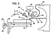
図1と図2を参照し、また表面22に沿った任意の箇所から試料を収集できるようにするために、収集管23は、その先端26と共に、固定された静止状態で支持され、またサンプリング表面22は、示されたX−Y座標軸に沿って(即ち、支持板27の平面内で)また示されたZ座標軸に沿って収集管23に対して移動され、収集管23の先端26から近づき遠ざかるように、支持板27上に支持される。示されたシステムの支持板27は、例えば、分析したい物質量が配置された薄層クロマトグラフィ(TLC)板の形をとることができる。したがって、本明細書の説明のため、サンプリング表面22は、X−Y平面(ほぼ水平面に対応する)内で支持板27によって支持され、Z軸はX−Y平面と垂直である。
With reference to FIGS. 1 and 2, and in order to be able to collect samples from any location along the
放射器25は、毛細管23に対して所定の位置に固定され、表面22に対して事前に設定された関係で配置され、それにより、小出しされた噴流(気体または液体)が、表面22に所定の入射角で当たる。したがって、試料収集結果を最適なものにするためには、毛細管23と放射器25と表面22との間に望ましい関係(すなわち、空間的割り当て)が存在することになる。
The
支持板27は、支持板27を動かすためにXYZステージ28(図1)の可動支持アーム36に支持され取り付けられ、それにより表面22が、示されたX、YおよびZ座標方向に沿って支持される。XYZステージ28は、コマンド信号を受け取るための第1の制御コンピュータ30に接続されたジョイスティック制御ユニット29に適切に配線され、これにより、システム20によって行われるサンプリング・プロセス中に、表面22が収集管先端26の下でX−Y平面内で動かされたときに表面22または表面22を横切る任意の所望のレーンに沿った(すなわち、XまたはY座標経路に沿った)任意の所望の箇所(すなわち、任意の所望のX−Y座標位置)から試料を得ることができる。
The
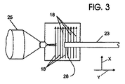
例えば、図3では、表面22が、毛細管先端26の下で割り出しされ、矢印18で示された複数のY座標レーン(すなわち、経路)に沿って順に移動されるときに表面22から試料を収集するために表面22の上の所定の位置に配置された放射器25と毛細管23の図が示される。掃引速度や収集管23を表面22と位置決めしたいX−Y位置の識別などの表面22と毛細管23の相対運動の特徴は、例えばコンピュータ・キーボード31によってコンピュータ30に入力されてもよく、コンピュータ30のメモリ33にあらかじめプログラムされてもよい。
For example, in FIG. 3, a sample is collected from the
XYZステージ28の内部構成要素の説明が必要とは思われないが、ここでは、収集管先端26に対する支持面27(および、表面22)のXおよびY座標位置が、例えば、XYZステージ28内部に取り付けられた1対の可逆サーボモータ(図示せず)の適切な動作によって制御され、収集管先端26に対する支持面27(および、表面22)のZ座標位置が、例えば、XYZステージ28の内部に取り付けられた可逆ステップモータ(図示せず)の適切な動作によって制御されるとだけを説明しておく。したがって、XおよびY座標サーボモータに適切に通電することによって、収集管23の先端26を表面22のX−Y座標平面内の任意の箇所と合うように位置決めできるように表面22を位置決めすることができ、またZ軸ステッピング・モータに適切に通電することによって、表面22を収集管先端26に近づけまたは遠ざけることができる。
Although it does not seem necessary to describe the internal components of the
更に図1を参照すると、示された例のシステム20は、さらに、収集管23に接続されて分析のために送り込まれた試料を受け入れる質量分析計32を有し、質量分析計32は、質量分析計32の操作と機能を制御するための第2の制御コンピュータ34と関連付けられる。質量分析計32のように、示されたシステム20と共に使用するのに適した質量分析計の例は、カナダ国オンタリオのMDS SCIEX of Concordから商品名4000 Qtrapで入手可能である。システム構成要素(質量分析計32を含む)の種々の動作を制御するために、示されたシステム20内では2つの別々のコンピュータ30および34が利用されるが、システム20内で実行される全ての動作は、本発明にとっては、単一のコンピュータで制御されてもよく、あるいは質量分析計ソフトウェアパッケージ内にロードされた適切なソフトウエアコンポーネントによって制御されてもよい。この後者の例では、単一ソフトウェア・パッケージは、毛細管−表面間距離の監視と質量分析検出の監視の最中に行われるXYZステージ操作、計算(本明細書で述べる)を制御することになる。
Still referring to FIG. 1, the
示されたシステム20の特徴は、収集管23の先端26と表面22との離間距離(すなわち、示されたZ座標軸方向に測った距離)を監視し制御するために全体が40で示された距離測定手段を含むことである。示されたシステム20内で、距離測定手段40は、表面22の真上(すなわち、Z座標軸方向)に支持されたレーザ・センサ42を含む。必要に応じて、試料収集操作中に画像を収集するための閉回路カラーカメラ44を表面22の上に支持することができ、カメラ44に、カメラ44によって収集された画像を受け取り表示するためのビデオ(例えば、テレビ)モニタ46を接続することができる。モニタ46は、カメラ44によって撮影された画像に対応する信号をコンピュータ30に伝えるために、第1の制御コンピュータ30に(ビデオ・キャプチャ装置50によって)接続される。オペレータは、そのようなカメラで生成した画像を使用して、試料収集プロセス中のイベントを視覚的に監視し記録することができる。
The features of the
さらに、システム20は、毛細管23と表面22の広角ビューをオペレータに提供するために、ほぼ収集管23と表面22の方に向けられかつコンピュータ30に接続されたレンズ付きウェブカメラ48を備える。オペレータは、試料収集操作に備えて毛細管23に対する表面22の初期位置決めを容易にするために、ウェブカメラ48によって収集された画像を、第1の制御コンピュータ30と関連付けられたディスプレイ画面(52で示された)上で見ることができる。
In addition, the
カメラ44として使用するのに適した閉回路カメラの一例は、Panasonic Matsushita Electric Corporationから商品名Panasonic GP−KR222で入手可能であり、カメラ44は、商品名Optem70XLとしてニューヨーク州フェアポートのThales Optem Inc.から入手可能なズームレンズを備える。ビデオ・キャプチャ装置50として使用するのに適したビデオ・キャプチャ装置の例は、カリフォルニア州カンプトンのBelkin Corp.から商品名Belkin USB VideoBus IIで入手可能であり、ウェブカメラ48として使用するのに適したウェブカメラの例は、カリフォルニア州ミルピータスのW.Creative Labs Inc.から商品名Creative Notebook Webcamで入手可能である。
An example of a closed circuit camera suitable for use as the camera 44 is available from Panasonic Matsushita Electric Corporation under the trade name Panasonic GP-KR222; With a zoom lens available from An example of a video capture device suitable for use as the
システム20とその距離測定手段40の動作は、距離測定手段40を使用することにより、システム20が、収集管23とサンプリング表面22の間の距離の実時間測定を監視し、その後で、必要に応じて、コンピュータ30とXYZステージ28によって実際の毛細管−表面間距離の調整を行い、それにより、表面22に沿った他の箇所または表面22を横切る様々なレーンに沿った箇所から試料を収集するために表面22がXまたはY座標軸方向に移動される場合でも、サンプリング・プロセス全体にわたって最適または望ましい毛細管−表面間距離(Z軸に沿って測った)が維持されるというシステム動作の説明によってよりよく理解することができる。
The operation of the
システム20により実行される試料収集操作の一実施形態の最初に、毛細管23の先端26が、試料を収集するのに毛細管23と表面22の間の最適または望ましい距離に対応する望ましい毛細管−表面間距離に位置決めされ(操作の準備段階で)、この最適距離は、(本明細書に述べた技術によって)決定され第1の制御コンピュータ30のメモリ33に記憶される。毛細管23とのそのような望ましい関係での表面22の位置決めは、XYZステージ28のジョイスティック制御ユニット29の適切な(例えば、手動)操作によって達成され、この位置決めは、オペレータが、操作のこの準備段階でテレビモニタ46を見ながら視覚的に監視される。表面22が、毛細管23とその望ましい位置関係で位置決めされた後で、レーザ・センサ42と表面22とのこの最初の(かつ実際の)距離に対応する信号が、距離測定手段40によって生成され、記憶し(すなわち、コンピュータ30のメモリ内に)後で使用するためにコンピュータ30に送られる。
At the beginning of one embodiment of the sample collection operation performed by the
そのような所望の毛細管−表面間距離での毛細管先端23の前述の手動準備が、完全に自動化された操作でなくてもよいことを理解されよう。例えば、連続的な試料収集操作中にXYZステージ28の再調整が不要な場合がある。したがって、同様に取り付けられた表面を含む第2またはその後の試料収集操作では、毛細管−表面間距離を最適な状態に繰り返し設定することなく、適切なコマンドをコンピュータ30に出して試料収集操作を開始することができる。
It will be appreciated that the aforementioned manual preparation of the
前述し、図4aと図4bに示されたように、距離測定手段40のレーザ・センサ42は、表面22の真上に配置される。測定し決定するために、レーザ・センサ42は、表面22の方または支持体22と並んで配置された支持体平面27の(上側)表面上の任意の場所に向けることができる。従って、本明細書で使用されるとき、語句「レーザ・センサ−表面間距離」(図4aと図4bにdPOS/LSと示された)は、レーザ・センサと表面との実際の距離、またはレーザ・センサと、表面22が支持された支持体平面27の(上側)表面上の位置と間の実際の距離と解釈することができ、そのような位置は、表面22のそばにある。
As described above and shown in FIGS. 4 a and 4 b, the
距離測定手段40のレーザ・センサ42のような、レーザ・センサから対象物まで距離を測定するためのレーザ・センサの使用は知られており、従って、レーザ・センサの動作の詳細な説明と構造詳細は、必要とは考えられない。従って、測定のために使用される一般的なレーザ・センサがレーザ光線を対象物の方に放射し、次にビームが対象物からセンサの方に反射されることだけを説明しておく。反射したビームは、レーザ・センサによって検出され、レーザ光線が往復するのに必要な期間が検出される。次に、レーザ・センサと対象物との距離が、経過時間(レーザ光線の往復)の2分の1にレーザ光線の速度を掛けたものに等しくなるように計算される。
The use of laser sensors for measuring the distance from a laser sensor to an object, such as the
図5aを参照すると、毛細管23と表面22の位置関係(すなわち、距離)が試料収集に最適なときの、レーザ・センサ42と毛細管26と示されたシステム20の表面22との典型的な関係が示される。より具体的には、表面22は、一般にX−Y平面内にあり、毛細管23は、表面22のすぐ上に配置され、レーザ・センサ42は、表面22と反対の毛細管23の側に配置される。
Referring to FIG. 5a, a typical relationship between the
さらに、レーザ・センサ42は、毛細管26と関連して固定される。換言すると、レーザ・センサ42と毛細管23の間の測定されたZ座標距離(図4a、図4bおよび図5aでdSC/LSと示された)は、操作中に表面22が上昇または下降された(XYZステージ28によって)場合でも試料収集操作中ずっと一定でなければならない。したがって、レーザ・センサ42と毛細管23の間の距離(図4a、図4bおよび図5aに示されたdSC/LS)と毛細管23の厚さが分かった後で、毛細管23と表面22の間の実際の距離を決定したい場合は、レーザ・センサ42と表面22の間の距離(dPOS/LS)から毛細管23の厚さを引くことによって、毛細管23と表面22との距離を計算することができる。
Furthermore, the
この設定段階(すなわち、毛細管−表面間距離がその最適値に設定されたとき)でレーザ・センサ42と表面22の間の実際の距離が決定された後で、このレーザ源−表面間距離が、コンピュータ30に記憶され、目下の目的のために、試料収集プロセス中ずっと維持したいターゲット・レーザ・センサ−表面間距離として指定される。換言すると、ターゲット・レーザ源−表面間距離は、コンピュータ30内に記憶され、表面22の所望の位置からまたは表面22を横切る所望のレーンに沿って試料を収集するために、表面22をX−Y平面に沿って毛細管23に対して移動させることによりサンプリング・プロセスを開始することができる。サンプリング・プロセス中に、レーザ・センサ42と表面22の間の実際の距離が、距離測定手段40によって周期的に測定され、次に、それぞれの測定された実際のレーザ・センサ−表面間距離が、ターゲット・レーザ・センサ−表面間距離と比較され、必要に応じて、実際のレーザ・センサ−表面間距離をターゲット・レーザ・センサ−表面間距離の近くに維持するように調整される。
After the actual distance between the
比較のために、コンピュータ30(すなわちそのメモリ30)が、ターゲット距離に対して許容可能な距離(すなわち、許容)限度に関する情報によって事前にプログラムされることを理解されよう。換言すると、実際のレーザ・センサ−表面間距離が、ターゲット・レーザ・センサ−表面間距離と、そのような許容限度を超える大きさだけ異なることが分かった場合は、コマンドがXYZステージ28に送られて、実際の距離をターゲット・レーザ源−表面間距離(すなわち、許容限度内)に合うように戻すために、毛細管23と表面22の間のZ軸調整が開始される。従って、そのような事前設定された許容限度は、実際のレーザ源−表面間距離が、表面22が毛細管23に近づくか遠ざかる追加の動きを必要とすることなく望ましいターゲットレーザ源−表面間距離に十分に近づくことができる所定の範囲(例えば、±3μm以内)に対応することなる。
For comparison purposes, it will be appreciated that the computer 30 (ie, its memory 30) is pre-programmed with information regarding acceptable distance (ie, acceptable) limits for the target distance. In other words, if the actual laser sensor-to-surface distance is found to differ from the target laser sensor-to-surface distance by an amount that exceeds such tolerances, commands are sent to the
図5aと図5bを参照すると、毛細管−表面間距離が試料収集に最適でないときの、レーザ・センサ42と毛細管23と表面22の間の例示的な関係が示される。比較として、前に言及したように、図5aの図に示された構成要素関係における毛細管−表面間距離は、試料収集に最適になるように取られ、従って、この図5aの関係におけるレーザ・センサ−表面間距離は、試料収集操作の設定段階で決定される。しかしながら、図5bの例では、レーザ・センサ−表面間距離(dPOS/LS)は、設定段階で決定されたレーザ・センサ−表面間距離よりも大きく、従って、毛細管23と表面22の間に望ましい幅より大きい隙間ができたことを示す。図5bの例の決定されたレーザ・センサ−表面間距離が、事前設定された許容限度を超えた場合、コンピュータ30は、適切なコマンドを出して(XYZステージ28によって)表面22を毛細管23に近づけることを開始し、その結果、実際のレーザ・センサ−表面間距離が、ターゲット・レーザ・センサ−表面間距離(例えば、操作の設定段階中に決定されたレーザ・センサ−表面間距離)に近づく。
Referring to FIGS. 5a and 5b, an exemplary relationship between the
同様に、図5cの例では、レーザ・センサ−表面間距離(dPOS/LS)は、設定段階で決定された望ましいレーザ・センサ−表面間距離より小さく、従って、毛細管23と表面22の間に望ましい幅より小さい隙間ができたことを示す。実際には、そのような判断は、毛細管23が表面22によって上方に曲げられたことを示す可能性がある。図5cの例の決定されたレーザ・センサ−表面間距離が、事前設定された許容限度を超える場合、コンピュータ30は、適切なコマンドを出して(XYZステージ28によって)表面を毛細管23から遠ざけることを開始し、その結果、実際のレーザ・センサ−表面間距離が、ターゲット・レーザ・センサ−表面間距離(すなわち、操作の設定段階で決定されたレーザ・センサ−表面間距離)に近づく。
Similarly, in the example of FIG. 5c, the laser sensor-to-surface distance (d POS / LS ) is less than the desired laser sensor-to-surface distance determined in the setup stage, and thus between the capillary 23 and the
したがって、本発明の一実施形態により、試料収集プロセス中の実際の毛細管−表面間距離の制御が一連の段階で構成されることが分かる。最初に、システム20で実行される試料収集操作に備えて、オペレータは、表面22のZ軸位置を、表面22が毛細管23の先端26の比較的すぐ近くに位置決めされて毛細管先端−表面間距離が試料収集に最適になるまで調整する。この設定段階で、表面22と毛細管先端26の間の相対位置は、ウェブカメラ48によって取得されコンピュータ表示画面52に表示された画像を見るオペレータによって視覚的に監視することができる。しかしながら、前述のように、完全に自動化された操作ではこの初期設定段階を省略できることが理解されるであろう。
Thus, it can be seen that according to one embodiment of the present invention, the actual capillary-to-surface distance control during the sample collection process consists of a series of steps. Initially, in preparation for a sample collection operation performed in the
この設定段階において、表面22が毛細管先端26と望ましい位置関係になった後で、オペレータは、適切なコマンドをキーボード31によってコンピュータ30に入力し、その結果、初期(および、実際の)レーザ・センサ−表面間が、距離測定手段40により決定される。これに関連して、実際のレーザ・センサ−表面間距離を測定するために距離測定手段40(レーザ・センサ42による)が使用され、測定された距離に対応する信号が、距離測定手段40からコンピュータ30に伝えられる。この初期レーザ・センサ−表面間距離は、コンピュータ・メモリ30内に記憶され、目下の目的のために、後で決定される実際のレーザ・センサ−表面間距離と最終的に比較されるターゲット・レーザ・センサ−表面間距離として指定される。
At this setting stage, after the
次に、試料収集プロセスが行われるとき、距離測定手段40によって、実際のレーザ・センサ−表面間距離の定期的測定が行われる。そのような測定距離に対応する電気信号は、ターゲット・レーザ・センサ−表面間距離と比較するために、直ちにコンピュータ30に送られる。そのような定期的測定は、あらかじめ選択され規則的な時間間隔(例えば、0.5秒ごと)で行うことができ、そのような実際のレーザ・センサ−表面間距離を得る時間間隔は、コンピュータ30に事前にプログラムされてもよく、コンピュータ30で選択されてもよい。
Next, when the sample collection process is performed, the distance measurement means 40 periodically measures the actual laser sensor-surface distance. The electrical signal corresponding to such a measured distance is immediately sent to the
収集された試料の分析に関しては、収集管23を通して表面22から収集された試料は、質量分析計32に導かれ、そこで当該技術分野で既知の方式で分析される。必要に応じて、ディスプレイ画面38とキーボード39を備えた第2の制御コンピュータ34(前に紹介し図1に示された)が質量分析計32に接続され、質量分析計32の動作を制御することができる。換言すると、キーボード39を使用して、コンピュータ34にコマンドを入力し、それにより質量分析計32の動作とデータ収集を制御することができる。
For analysis of collected samples, the sample collected from
システム20により実行される試料収集動作において、表面22は、毛細管23に対してX−Y平面内で移動され、これにより、表面22がプローブ24の下で動くときに毛細管23の先端26が表面22をサンプリングすることは一般的である。このために、例えば、コンピュータ30は、毛細管先端26による試料収集位置に代替位置(または箇所)を位置決めして代替位置で試料を得るために表面22をX−Y平面内で割り出すか、表面22を横切る特定のレーン(図3の経路18など)に沿って毛細管23で表面22をサンプリングするようにXまたはY座標軸方向に表面を移動させるように、あらかじめプログラムされてもよい。
In the sample collection operation performed by the
図6aと図6bを参照すると、試料収集動作において表面22が毛細管先端26の下を通るときの表面22と毛細管先端26との位置関係と、毛細管−表面位置の再最適化における毛細管先端26の動きを概略的に示す。(図6aと図6bの両方で、表面22は、例示のために毛細管23の縦軸に対して誇張された角度で示される。)より具体的には、図6aでは、表面22と毛細管23は互いに、試料収集プロセスで試料が表面22のレーンから試料が収集されるように、矢印62で示された負の(−)X座標方向に動かされ、図6bでは、表面22と毛細管23は互いに、試料収集プロセスで試料が表面22のレーンから収集されるように、矢印63で示された正の(+)X座標方向に動かされる。
6a and 6b, the positional relationship between the
一方、図6aと図6bに示された点線64および66は、表面22と毛細管先端26の間に試料収集に最適または望ましい距離を維持するために、毛細管先端26を位置決めしなければならない外側境界またはあらかじめ設定された限度を示す。例えば、毛細管26と表面22の間の最適距離を試料収集の最適距離に対応する距離に維持するために、毛細管先端26を(Z軸に沿って)線64より表面22に近づけてはならず、また毛細管先端26を表面22から線66より遠ざけてはならない。実際には、(Z軸方向に測定されたような)あらかじめ設定された限度間の離間距離が、互いから約6μmなどの数マイクロメートル以内でよく、これにより、あらかじめ設定された限度(点線64および66に対応する)はそれぞれ、表面22が毛細管先端26に対して最適に調整された関係でターゲット距離から約3μmに離間される。従って、システム20によって実行される試料収集操作において、実際のレーザ・センサ−表面間距離は、離れた時間間隔で決定され、それらの実際のレーザ・センサ−表面間距離に対応する適切な信号が、コンピュータ30に送られる。
On the other hand, the dotted
次に、それぞれの測定された実際のレーザ・センサ−表面間距離は、コンピュータ30で動作している適切なソフトウェア70(図1)によって、レーザ・センサ42と表面22との所望のターゲット距離と比較され、このターゲット距離は、規定された限度線64および66(図6aまたは図6b)によって定められる。実際のレーザ・センサ−表面間距離が、規定された限度線64および66内にあると判断された場合は、表面22と毛細管先端26のZ軸方向の相対的な動きまたは調整は不要である。しかしながら、実際のレーザ表面−表面間距離が、規定された限度線64および66上またはその外にあると判断された場合は、実際のレーザ・センサ−表面間距離を限度線64および66に対応する規定された限度内に戻すために、表面22と毛細管先端26との相対移動または相対位置の調整が必要である。したがって、図6aに示されたような試料収集操作では、毛細管23が表面22に対して負(−)のX座標軸方向に移動されるときはZ軸方向の表面22と毛細管23の頻繁な調整を行わなければならず、表面22に対して毛細管先端26が辿る経路は、階段状経路68によって示すことができる。
Each measured actual laser sensor-to-surface distance is then calculated by the appropriate software 70 (FIG. 1) running on the
これと比較し、図6bに示された試料収集操作では、毛細管23が表面22に対して正(+)の座標軸方向に移動されるときはZ軸方向の表面22と毛細管23の頻繁な調整を行わなければならず、表面22に対して毛細管先端26が辿る経路は、階段状経路69によって示すことができる。
In contrast, in the sample collection operation shown in FIG. 6b, frequent adjustment of the
前述したように、レーザ・センサ−支持体間平面をレーザ・センサ−表面と一致させることによって(レーザ・センサ42を使用して、表面22自体までの距離ではなく、表面22と並置された支持体平面27上の位置までの距離を測定する場合のように)、特に支持体平面27がX−Y平面に対して大きな角度で傾けられている場合は、誤差の原因になる可能性がある。しかしながら、支持体平面27がX−Y平面に対して傾けられている場合は、そのような誤差を補正することができる。例えば、図7に、表面22がX−Y平面に対してω度の角度で傾けられた場合のレーザ源と表面との関係が示される。この図7で、実際のレーザ・センサ−表面間距離(Z座標方向)(すなわち、dPOS/LS)が、毛細管23と表面22の間のZ軸方向の距離を間違って表わしていることが分かる。
As described above, by aligning the laser sensor-support plane with the laser sensor-surface (using the
出願人により使用されているシステム20では、レーザ源42から放射されたビームの線と毛細管の中心との間のY軸方向距離は約500のμmである。出願人は、また、例えば、角度ω(すなわち、表面22の傾斜角度)が約1度(実際には、とても小さくて手動で調節するのが難しい)の場合は、tan(ω)と500μmの積がわずか約9μmであること分かった。この9μmの値は、許容可能な誤差であり、表面全体にわたって検出される信号レベルに大きな影響を及ぼす可能性は低い。そのような誤差が許容可能でない場合、システムは、2つのレーザ・センサを使用して、Z軸距離に沿ったレーザ・センサ−表面間距離のより正確な表現を得ることができる。
In the
例えば、図8に、毛細管123から等距離でその両側に下向きのビームを放射するために、表面122、毛細管123、および毛細管123の上に配置された1対のレーザ・センサ142と143を含むシステムの一部(全体が120で示された)が示される。レーザ・センサ−表面間距離の正確な計算は、2つのレーザ・センサ142,143によって測定されたレーザ・センサ−表面間距離を平均することにより得ることができる。この計算から得られる値を、毛細管123と表面122の間のZ軸距離を表すように取って、X−Y平面に対する表面122の傾きよって生じる誤差の可能性を小さくすることができる。
For example, FIG. 8 includes a surface 122, a capillary 123, and a pair of
したがって、以上のことから、試料収集装置を利用する表面サンプリング・プロセスにおいて毛細管−表面間距離を制御するためのシステム20およびそれに関連した方法を述べた。これに関連して、システム20は、レーザ・センサ42によって得られた距離測定値を使用して試料収集機器−表面間距離の実時間再最適化の構築を自動化する。距離測定分析は、レーザ・センサ42と表面22の間の実際の距離を定期的に測定し、その後で実際のレーザ・センサ−表面間距離のそれぞれをターゲット・レーザ・センサ−表面間距離と比較することを含む。次に実際のレーザ・センサ−表面間距離を、(例えば手順の準備段階で確立することができる望ましい毛細管−表面間距離に対応する)ターゲット・レーザ・センサ−表面間距離と比較することによって、システム20は、必要に応じて、離間されたレーザ・センサ−表面間距離をZ座標軸方向に調整することによって、試料収集手順における毛細管−表面間距離を自動的かつ連続的に再最適化することができる。
Thus, the foregoing has described a
必要に応じて、表面22をX−Y平面に沿って(かつ毛細管23に対して)移動させて、表面22上の等しい間隔または個別化された間隔の複数の平行レーンに沿って、毛細管23によって試料を自動収集することができる。前述のシステム20により、試料を一定の走査速度または個別化された(即ち、様々な)走査速度で収集することができる。
If necessary, the
試料収集プロセス全体にわたって毛細管−表面間距離を制御するためのシステム20および関連方法によって提供される基本的な利点は、試料収集プロセスにおける毛細管−表面間距離の(すなわち、Z座標軸方向の)操作介入および手動制御を不要にすることに関係する。したがって、システム20により行われる試料収集操作の精度が、試料収集プロセスを監視するために必要なオペレータの技術によって限定されない。さらに、システム20はまた、毛細管23によって収集される試料の精度に直接影響を及ぼす利点を有する。例えば、試料収集プロセス全体にわたって最適または望ましい毛細管−表面間距離が維持されるので、表面22が不正確にサンプリングされ、収集された試料が分析されるときに誤って解釈される可能性を実質的に減少させる。
A fundamental advantage provided by the
前述のシステム20および方法は、互いに望ましい空間的関係(すなわち、割り当て)で位置決めされるように設計されたノズルチップを有する放射器25などの部品を使用する試料収集機器においてさらなる利点を提供する。例えば、ノズルチップとサンプリング表面が、一般に、試料収集操作において互いに固定関係で配置された試料収集システムでは、ノズルチップ−表面間距離が変化すると、それに対応する大きさだけサンプリング毛細管−表面間距離が変化することになる。しかしながら、本発明のシステム20および方法は、試料収集プロセスにおいて望ましい毛細管−表面間距離を維持するのに役立つので、このシステム20および方法は、放射器と収集管とサンプリング表面の間に望ましい空間的関係を維持するのにも役立つ。
The
本発明の精神から逸脱することなく前述の実施形態に多数の修正および置換を行うことができることを理解されよう。例えば、前述の実施形態では、毛細管23が、固定静止状態で示され、表面22が、X,YまたはZ座標方向のいずれかの方向に毛細管23に対して移動されて、所望の箇所または現像レーンを毛細管23と位置合わせするように示し説明したが、本発明の幅広い態様による代替実施形態は、固定静止状態で支持された表面と、X、YまたはZ座標方向のいずれかに沿って表面に対して移動可能な毛細管を、毛細管との関係が固定されたレーザ・センサと共に含むことができる。したがって、前述の実施形態は、限定としてではなく例示のためのものである。
It will be appreciated that numerous modifications and substitutions may be made to the above-described embodiments without departing from the spirit of the invention. For example, in the above-described embodiment, the capillary 23 is shown in a stationary stationary state, and the
20…システム、22…表面、23…収集機器、40…距離測定装置、42…レーザ・センサ。
DESCRIPTION OF
Claims (17)
前記収集機器と前記表面の間で前記表面から物質試料を収集できるように、両者の望ましい位置関係を得るため、前記収集機器と前記表面を互いに近づけたり遠ざけるたりするための手段と、
レーザ・センサと前記表面の間の実際の距離に対応する信号を生成するために、前記収集機器に対して固定された位置関係で前記表面の真上に配置されたレーザ・センサを含み、前記収集機器と前記表面が物質試料の収集をする位置関係で配置されたときに、前記レーザ・センサと前記表面の間にターゲット距離を有する距離測定手段と、
前記レーザ・センサと前記表面の間の前記実際の距離に対応する信号を受け取るための手段と、
前記レーザ・センサと前記表面の間の前記実際の距離を前記レーザ・センサと前記表面の間の前記ターゲット距離と比較し、試料収集中に前記レーザ・センサと前記表面の間の前記実際の距離と前記ターゲット距離との差が所定の範囲を超えたときに、試料収集中に前記レーザ・センサと前記表面を互いに近づけたり遠ざけたりすることを開始し、それによって、前記レーザ・センサと前記表面の前記実際の距離が前記ターゲット距離に近づくようにする比較手段と、
から構成されることを特徴とするサンプリング・システム。 A collection device that collects a sample from the surface to be analyzed and is arranged substantially parallel to the surface;
Means for moving the collection device and the surface closer to or away from each other in order to obtain a desired positional relationship between the collection device and the surface so that a material sample can be collected from the surface;
To generate a signal corresponding to the actual distance between the LES over The sensor and the surface, comprising a laser sensor that is located directly above the fixed said surface in a positional relationship with respect to the collection device A distance measuring means having a target distance between the laser sensor and the surface when the collecting device and the surface are arranged in a positional relationship for collecting a material sample;
Means for receiving a signal corresponding to the actual distance between the laser sensor and the surface;
The actual distance between the laser sensor and the surface is compared with the target distance between the laser sensor and the surface, and the actual distance between the laser sensor and the surface during sample collection And starting the laser sensor and the surface closer to or away from each other during sample collection when the difference between the target distance and the target distance exceeds a predetermined range, whereby the laser sensor and the surface Comparing means for causing the actual distance of the to approach the target distance;
A sampling system characterized by comprising:
前記比較手段によって比較された前記実際の距離が平均化された実際の距離となるように、生成された前記信号が対応する前記実際の距離を平均化するための計算手段をさらに含むことを特徴とする請求項1に記載のシステム。 The laser sensor is a first laser sensor, and the distance measuring means is disposed in a fixed positional relationship with respect to the collection device, and the actual distance between the second laser sensor and the surface. It comprises a second laser sensor for generating a signal corresponding to said first and second laser sensors, the actual distance between the first and second laser sensor and the surface Arranged on both sides of the collecting device for generating a signal corresponding to
Wherein as the actual distance is compared by the comparison means is the actual distance, averaged, to further include a calculation unit for averaging the actual distance that were generated the signal corresponding The system of claim 1, characterized in that:
前記収集機器と固定された位置関係で前記表面の真上に取り付けられたレーザ・センサを含み、前記レーザ・センサと前記表面の間の実際の距離に対応する信号を生成する距離測定手段と、
前記収集機器と前記表面とが、前記表面からの物質試料を収集するのに望ましい位置関係にあるときの、前記レーザ・センサと前記表面の間のターゲット距離に関係する情報を含むコンピュータと、
前記コンピュータに接続されており、前記コンピュータから受け取ったコマンドに応じて、前記表面と前記レーザ・センサを近づけたり遠ざけたりするための手段と、
から構成され、
前記コンピュータは、前記レーザ・センサと前記表面の間の前記実際の距離に対応する前記信号を受け取るための手段を含み、
前記コンピュータは、試料収集中に前記レーザ・センサと前記表面の間の前記実際の距離と前記ターゲット距離を比較し、前記実際の距離が所定の範囲を超えたときに前記表面と前記レーザ・センサを互いに近づけたり遠ざけたりすることを開始して、試料収集中に前記実際の距離は前記ターゲット距離に近づくようにし、このとき前記表面と前記レーザ・センサを互いに近づけたり遠ざけたりする動作は、前記レーザ・センサと前記表面の相対的な動きではなく、前記実際の距離と前記ターゲット距離の差によって開始される、
ことを特徴とするサンプリング・システム。 Collecting a sample of material from the surface to be analyzed, comprising a collection device disposed substantially parallel to the surface, and collecting a sample from the surface between the collection device and the surface; The surface sampling system where the desired positional relationship exists is
A distance measuring means comprising a laser sensor mounted directly above the surface in a fixed positional relationship with the collecting device, and generating a signal corresponding to an actual distance between the laser sensor and the surface;
A computer including information related to a target distance between the laser sensor and the surface when the collection device and the surface are in a desired positional relationship for collecting a material sample from the surface;
Means connected to the computer and for moving the surface and the laser sensor closer or away in response to a command received from the computer;
Consisting of
The computer includes means for receiving the signal corresponding to the actual distance between the laser sensor and the surface;
The computer compares the target distance with the actual distance between the laser sensor and the surface during sample collection, and the surface and the laser sensor when the actual distance exceeds a predetermined range. To bring the actual distance closer to the target distance during sample collection, the action of moving the surface and the laser sensor closer to or away from each other is as follows. Initiated by the difference between the actual distance and the target distance, rather than the relative movement of the laser sensor and the surface ,
A sampling system characterized by this.
レーザ・センサと前記表面の間の実際の距離に対応する信号を生成するレーザ・センサを含み、前記レーザ・センサを前記収集機器に対して固定された位置関係で前記表面の真上に配置するための距離測定手段を提供するステップと、
前記レーザ・センサと前記表面とを互いに近づけたり遠ざけるたりすることができるように、前記レーザ・センサと前記表面を互いに支持し、前記収集機器と前記表面が互いに対して望ましい位置関係で配置されたときに前記レーザ・センサと前記表面の間にターゲット距離が存在する、ステップと、
前記距離測定手段によって、前記レーザ・センサと前記表面の間の前記実際の距離に対応する信号を生成するステップと、
前記距離測定手段によって生成された信号から、前記レーザ・センサと前記表面の間の実際の距離を決定するステップと、
サンプル収集中に、前記レーザ・センサと前記表面の間の前記実際の距離を前記ターゲット距離と比較し、前記レーザ・センサと前記表面の間の前記実際の距離と前記ターゲット距離との差が所定の範囲を超えたときに、前記表面と前記レーザ・センサを互いに近づけるたり遠ざけたりする動作を開始し、それによってサンプル収集中に、前記実際の距離が望ましい前記ターゲット距離に近づくようにする、ステップと、
から構成されることを特徴とする、被分析表面をサンプリングする方法。 A step of collecting a material sample from the analysis table surface, preparing a collection device which is disposed substantially parallel to said surface,
Including a laser sensor that generates a signal corresponding to an actual distance between the laser sensor and the surface, the laser sensor being positioned directly above the surface in a fixed positional relationship with respect to the collection device Providing a distance measuring means for:
The laser sensor and the surface are supported from each other so that the laser sensor and the surface can be moved closer to and away from each other, and the collecting device and the surface are arranged in a desired positional relationship with respect to each other. A target distance sometimes exists between the laser sensor and the surface; and
Generating a signal corresponding to the actual distance between the laser sensor and the surface by the distance measuring means;
Determining an actual distance between the laser sensor and the surface from the signal generated by the distance measuring means;
During sample collection, the actual distance between the laser sensor and the surface is compared with the target distance, and the difference between the actual distance between the laser sensor and the surface and the target distance is predetermined. when exceeding the range, it starts to or farther closer to the laser sensor and the surface to each other, whereby during the sample collection, the actual distance the is to approach desirable the target distance , Step and
A method for sampling a surface to be analyzed, comprising:
レーザ・センサと前記表面の間の実際の距離に対応する信号を生成するレーザ・センサを含み、前記レーザ・センサを前記収集機器に対して固定された位置関係で前記表面の真上に配置する距離測定手段を提供するステップと、
前記収集機器と前記表面とを互いに近づけたり遠ざけたりすることができるように前記収集機器と前記表面を互いに対して支持するステップと、
前記表面と前記収集機器とを、互いに最適な試料収集をするのに望ましい初期位置関係に移動させるステップと、
前記表面が前記収集機器とが前記望ましい初期位置関係にあるときに、前記レーザ・センサと前記表面の間の前記実際の初期距離を決定し、前記実際の初期距離を前記レーザ・センサと前記表面の間のターゲット距離として指定するステップと、
前記収集機器を前記表面を横断するように移動させることによって試料収集プロセスを開始するステップと、
前記試料収集中に、前記距離測定手段によって、前記レーザ・センサと前記表面の間の前記実際の距離に対応する距離移動信号を生成するステップと、
前記レーザ・センサと前記表面の間の前記実際の距離を前記レーザ・センサと前記表面の間の前記ターゲット距離と比較するステップと、
前記レーザ・センサと前記表面の間の前記実際の距離と前記ターゲット距離との差が、所定の範囲を超えたとき、前記試料収集中に前記表面と前記レーザ・センサを互いに近づけるたり遠ざけたりする動作を開始し、それによって前記実際の距離が望ましい前記ターゲット距離に近づくようにし、このとき前記表面と前記レーザ・センサを互いに近づけるか遠ざける動作は、前記レーザ・センサと前記表面の相対的な動きではなく、前記実際の距離と前記ターゲット距離の差によって開始されるステップと、
から構成されることを特徴とする被分析表面をサンプリングする方法。 Providing a collection device arranged to be substantially parallel to the surface for collecting a sample from the surface to be analyzed;
It includes a laser sensor for generating a signal corresponding to the distance actually between the laser sensor and the surface, located directly above the surface of the laser sensor in fixed positional relationship with respect to the collection device Providing a distance measuring means to:
Supporting the collection device and the surface relative to each other such that the collection device and the surface can be brought closer to or away from each other;
Moving the surface and the collection device to an initial positional relationship desirable for optimal sample collection relative to each other;
Determining the actual initial distance between the laser sensor and the surface when the surface is in the desired initial positional relationship with the collector; and determining the actual initial distance from the laser sensor and the surface. Specifying a target distance between, and
Initiating a sample collection process by moving the collection device across the surface;
Generating a distance movement signal corresponding to the actual distance between the laser sensor and the surface by the distance measuring means during the sample collection;
Comparing the actual distance between the laser sensor and the surface with the target distance between the laser sensor and the surface;
When the difference between the actual distance between the laser sensor and the surface and the target distance exceeds a predetermined range, the surface and the laser sensor are moved closer to or away from each other during the sample collection. starts operating, thereby to actual distance the approaches desirable the target distance, the operation away or this time closer to each other the laser sensor and the surface, relative to the laser sensor and the surface Starting with the difference between the actual distance and the target distance, rather than
A method for sampling a surface to be analyzed, comprising:
Applications Claiming Priority (3)
| Application Number | Priority Date | Filing Date | Title |
|---|---|---|---|
| US12/217,225 | 2008-07-02 | ||
| US12/217,225 US8117929B2 (en) | 2008-07-02 | 2008-07-02 | Control of the positional relationship between a sample collection instrument and a surface to be analyzed during a sampling procedure using a laser sensor |
| PCT/US2009/003347 WO2010002427A2 (en) | 2008-07-02 | 2009-06-02 | Control of the positional relationship between a sample collection instrument and a surface to be analyzed during a sampling procedure using a laser sensor |
Publications (3)
| Publication Number | Publication Date |
|---|---|
| JP2011527075A JP2011527075A (en) | 2011-10-20 |
| JP2011527075A5 JP2011527075A5 (en) | 2012-07-19 |
| JP5710473B2 true JP5710473B2 (en) | 2015-04-30 |
Family
ID=41327314
Family Applications (1)
| Application Number | Title | Priority Date | Filing Date |
|---|---|---|---|
| JP2011516271A Active JP5710473B2 (en) | 2008-07-02 | 2009-06-02 | Control of the positional relationship between the sample collection device and the surface to be analyzed in the sampling procedure using a laser sensor |
Country Status (5)
| Country | Link |
|---|---|
| US (1) | US8117929B2 (en) |
| EP (1) | EP2304766B1 (en) |
| JP (1) | JP5710473B2 (en) |
| CA (1) | CA2729701C (en) |
| WO (1) | WO2010002427A2 (en) |
Families Citing this family (9)
| Publication number | Priority date | Publication date | Assignee | Title |
|---|---|---|---|---|
| US8766177B2 (en) | 2010-10-11 | 2014-07-01 | University Of North Texas | Nanomanipulation coupled nanospray mass spectrometry (NMS) |
| JP2012237557A (en) * | 2011-05-09 | 2012-12-06 | Shimadzu Corp | Liquid sample collection apparatus and liquid sample collection method |
| US9176028B2 (en) | 2012-10-04 | 2015-11-03 | Ut-Battelle, Llc | Ball assisted device for analytical surface sampling |
| US10060838B2 (en) | 2015-04-09 | 2018-08-28 | Ut-Battelle, Llc | Capture probe |
| US9632066B2 (en) | 2015-04-09 | 2017-04-25 | Ut-Battelle, Llc | Open port sampling interface |
| WO2017181394A1 (en) * | 2016-04-21 | 2017-10-26 | 深圳市樊溪电子有限公司 | Oil-gas inclusion component sampling method |
| US11125657B2 (en) | 2018-01-30 | 2021-09-21 | Ut-Battelle, Llc | Sampling probe |
| WO2020242911A1 (en) * | 2019-05-31 | 2020-12-03 | Purdue Research Foundation | Integrated microfluidic probe (imfp) and methods of use thereof |
| CN116218649B (en) * | 2022-12-30 | 2024-07-02 | 德诺杰亿(北京)生物科技有限公司 | Automatic calibration method and device for sample loading table of gene analyzer and gene analyzer |
Family Cites Families (12)
| Publication number | Priority date | Publication date | Assignee | Title |
|---|---|---|---|---|
| JPH0687003B2 (en) * | 1990-02-09 | 1994-11-02 | 株式会社日立製作所 | Scanning electron microscope with scanning tunneling microscope |
| JPH04162337A (en) * | 1990-10-24 | 1992-06-05 | Hitachi Ltd | Electron beam device |
| DE4116803A1 (en) * | 1991-05-23 | 1992-12-10 | Agfa Gevaert Ag | DEVICE FOR THE UNIFORM ILLUMINATION OF A PROJECTION SURFACE |
| US5196713A (en) * | 1991-08-22 | 1993-03-23 | Wyko Corporation | Optical position sensor with corner-cube and servo-feedback for scanning microscopes |
| JP3015980B2 (en) * | 1992-01-10 | 2000-03-06 | キヤノン株式会社 | Atomic force microscope, recording / reproducing device and reproducing device |
| JP2002175770A (en) * | 2000-12-08 | 2002-06-21 | Hitachi Ltd | Sample chamber for gas exhaustion and circuit pattern forming device using the same |
| GB0112903D0 (en) * | 2001-05-26 | 2001-07-18 | Univ Heriot Watt | Permeability measurement apparatus and method |
| US6803566B2 (en) * | 2002-04-16 | 2004-10-12 | Ut-Battelle, Llc | Sampling probe for microarray read out using electrospray mass spectrometry |
| WO2005024390A1 (en) | 2003-09-03 | 2005-03-17 | Hitachi Kenki Fine Tech Co., Ltd | Probe manufacturing method, probe, and scanning probe microscope |
| US20080033275A1 (en) * | 2004-04-28 | 2008-02-07 | Blank Thomas B | Method and Apparatus for Sample Probe Movement Control |
| JP2006215004A (en) * | 2005-02-07 | 2006-08-17 | Ricoh Co Ltd | Near-field optical microscope and method for measuring sample by using near-field light |
| US7295026B2 (en) * | 2005-06-03 | 2007-11-13 | Ut-Battelle, Llc | Automated position control of a surface array relative to a liquid microjunction surface sampler |
-
2008
- 2008-07-02 US US12/217,225 patent/US8117929B2/en active Active
-
2009
- 2009-06-02 JP JP2011516271A patent/JP5710473B2/en active Active
- 2009-06-02 WO PCT/US2009/003347 patent/WO2010002427A2/en active Application Filing
- 2009-06-02 CA CA2729701A patent/CA2729701C/en active Active
- 2009-06-02 EP EP09773880.1A patent/EP2304766B1/en active Active
Also Published As
| Publication number | Publication date |
|---|---|
| CA2729701A1 (en) | 2010-01-07 |
| CA2729701C (en) | 2015-11-03 |
| JP2011527075A (en) | 2011-10-20 |
| EP2304766A2 (en) | 2011-04-06 |
| WO2010002427A2 (en) | 2010-01-07 |
| US8117929B2 (en) | 2012-02-21 |
| US20100000338A1 (en) | 2010-01-07 |
| WO2010002427A3 (en) | 2010-02-25 |
| EP2304766B1 (en) | 2019-07-31 |
Similar Documents
| Publication | Publication Date | Title |
|---|---|---|
| JP5710473B2 (en) | Control of the positional relationship between the sample collection device and the surface to be analyzed in the sampling procedure using a laser sensor | |
| JP5710472B2 (en) | Control of positional relationship between sample collection device and analysis surface in sampling process by image analysis | |
| JP5061103B2 (en) | Automatic position control of surface array for liquid microjunction surface sampler | |
| US9779926B2 (en) | Method and system for formation and withdrawal of a sample from a surface to be analyzed | |
| US8058610B2 (en) | Mass spectrometer | |
| US20050072915A1 (en) | Methods and apparatus for self-optimization of electrospray ionization devices | |
| US20200376672A1 (en) | Position detector and method for 3D position determination | |
| KR100795509B1 (en) | Inspection method of paste pattern | |
| WO2010113209A1 (en) | Mass spectrometry device | |
| WO2023193483A1 (en) | Automatic electrospray spraying apparatus and method for preparing mass spectrum imaging sample | |
| JP2014067709A (en) | Ionization device, mass spectrometer including the ionization device, or image generation system including the mass spectrometer | |
| US20230145540A1 (en) | Device for desorption scanning of analyte material on a sample support | |
| WO2023199273A1 (en) | High-throughput analysis using ion mobility and mass spectroscopy | |
| US20240288472A1 (en) | Probe Device | |
| JP4710710B2 (en) | Time-of-flight mass spectrometer | |
| EP3465731B1 (en) | Ambient ionisation spot measurement and validation | |
| JP4576609B2 (en) | Laser ionization mass spectrometry method and laser ionization mass spectrometer |
Legal Events
| Date | Code | Title | Description |
|---|---|---|---|
| A521 | Request for written amendment filed |
Free format text: JAPANESE INTERMEDIATE CODE: A523 Effective date: 20120601 |
|
| A621 | Written request for application examination |
Free format text: JAPANESE INTERMEDIATE CODE: A621 Effective date: 20120601 |
|
| A977 | Report on retrieval |
Free format text: JAPANESE INTERMEDIATE CODE: A971007 Effective date: 20130814 |
|
| A131 | Notification of reasons for refusal |
Free format text: JAPANESE INTERMEDIATE CODE: A131 Effective date: 20130827 |
|
| A131 | Notification of reasons for refusal |
Free format text: JAPANESE INTERMEDIATE CODE: A131 Effective date: 20140715 |
|
| A521 | Request for written amendment filed |
Free format text: JAPANESE INTERMEDIATE CODE: A523 Effective date: 20140911 |
|
| TRDD | Decision of grant or rejection written | ||
| A01 | Written decision to grant a patent or to grant a registration (utility model) |
Free format text: JAPANESE INTERMEDIATE CODE: A01 Effective date: 20150224 |
|
| A61 | First payment of annual fees (during grant procedure) |
Free format text: JAPANESE INTERMEDIATE CODE: A61 Effective date: 20150304 |
|
| R150 | Certificate of patent or registration of utility model |
Ref document number: 5710473 Country of ref document: JP Free format text: JAPANESE INTERMEDIATE CODE: R150 |
|
| R250 | Receipt of annual fees |
Free format text: JAPANESE INTERMEDIATE CODE: R250 |
|
| R250 | Receipt of annual fees |
Free format text: JAPANESE INTERMEDIATE CODE: R250 |
|
| R250 | Receipt of annual fees |
Free format text: JAPANESE INTERMEDIATE CODE: R250 |
|
| R250 | Receipt of annual fees |
Free format text: JAPANESE INTERMEDIATE CODE: R250 |
|
| R250 | Receipt of annual fees |
Free format text: JAPANESE INTERMEDIATE CODE: R250 |
|
| R250 | Receipt of annual fees |
Free format text: JAPANESE INTERMEDIATE CODE: R250 |
|
| R250 | Receipt of annual fees |
Free format text: JAPANESE INTERMEDIATE CODE: R250 |