JP5710333B2 - hood - Google Patents
hood Download PDFInfo
- Publication number
- JP5710333B2 JP5710333B2 JP2011069614A JP2011069614A JP5710333B2 JP 5710333 B2 JP5710333 B2 JP 5710333B2 JP 2011069614 A JP2011069614 A JP 2011069614A JP 2011069614 A JP2011069614 A JP 2011069614A JP 5710333 B2 JP5710333 B2 JP 5710333B2
- Authority
- JP
- Japan
- Prior art keywords
- air
- hood
- cover
- opening
- duct
- Prior art date
- Legal status (The legal status is an assumption and is not a legal conclusion. Google has not performed a legal analysis and makes no representation as to the accuracy of the status listed.)
- Expired - Fee Related
Links
Images


Description
本発明は、フードに関し、詳しくは、エンジンルームまたはトランクルームを形成するボンネットの開口を開閉可能なフードに関する。 The present invention relates to a hood, and more particularly to a hood that can open and close an opening of a bonnet that forms an engine room or a trunk room.
従来、例えば、図6に示すような、フード130とフロントガラス180との間に設けられたルーバー172から取り込んだエアaを、このルーバー172と共にカウル170を介して整流して車内の空調装置(図示しない)へ送り込む技術が既に知られている。これにより、簡便な構造で、車外から取り込んだエアaを整流して車内の空調装置へ送り込むことができる。
Conventionally, for example, air a taken in from a
しかしながら、上述した特許文献1の技術では、ルーバー172とカウル170とを必要とするため、部品点数の増加につながっていた。
However, the technique disclosed in
本発明は、このような問題点を解決しようとするもので、その課題は、簡便な構造で、車外から取り込んだエアを整流して車内の空調装置へ送り込むことができても、部品点数の増加を抑えることである。 The present invention is intended to solve such a problem, and the problem is that even if the air taken in from the outside of the vehicle can be rectified and sent to the air conditioner in the vehicle even with a simple structure, the number of parts can be reduced. It is to suppress the increase.
本発明は、上記の課題を達成するためのものであって、以下のように構成されている。
請求項1に記載の発明は、エンジンルームまたはトランクルームを形成するボンネットの開口を開閉可能なフードであって、アウタカバーと、このアウタカバーの内面に接合されたインナカバーとから成る二重構造となっており、これら両カバーの間には、その先端側に形成されたエア取込口から取り込んだエアを内部で整流し、この整流したエアを基端側に形成されたエア排出口から排出可能な第1のダクトが形成されており、エア排出口は、ボンネットの開口を閉じ状態にすると、車内の空調装置へエアを送り込み可能な第2のダクトの入口と連通可能に形成されており、インナカバーには、エンジンルーム内においてエンジンから発せられる熱がこもる熱滞留部へ外気を取り込むための開口が設けられており、インナカバーには、開口を開閉可能なカバーが付勢部材を介して取り付けられており、この付勢部材の付勢力は、車両の停止時には、カバーが閉じ状態を成すように、また、車両の走行時には、エア取込口から取り込んだエアによってカバーが開き状態を成すように設定されていることを特徴とする構成である。
この構成によれば、アウタカバーの内面にインナカバーを接合させることで第1のダクトを形成できるため、簡便な構造で第1のダクトを形成できる。そして、第1のダクトを介してエア取込口とエア排出口とを連通させることができると共に、第2のダクトを介してエア排出口と車内の空調装置とを連通させることができる。そのため、エア取込口からエアを取り込み、この取り込んだエアを第1のダクトの内部で整流し第2のダクトを介して、車内の空調装置へ送ることができる。したがって、従来技術の説明と同様に、簡便な構造で、車外から取り込んだエアを整流して車内の空調装置へ送り込むことができる。また、従来技術と比較すると、ルーバーが不要となるため、部品点数の増加を抑えることができる。すなわち、従来技術であれば、フード、ルーバー、カウルの3部品を必要としていたが、本発明では、フード、ホースの2部品で済ませることができる。
The present invention is for achieving the above-described problems and is configured as follows.
The invention according to
According to this configuration, since the first duct can be formed by joining the inner cover to the inner surface of the outer cover, the first duct can be formed with a simple structure. The air intake port and the air discharge port can be communicated with each other via the first duct, and the air discharge port and the air conditioner in the vehicle can be communicated with each other via the second duct. Therefore, air can be taken in from the air intake port, and the taken-in air can be rectified inside the first duct and sent to the air conditioner in the vehicle via the second duct. Therefore, similarly to the description of the prior art, the air taken from the outside of the vehicle can be rectified and sent to the air conditioner in the vehicle with a simple structure. In addition, compared with the prior art, a louver is not necessary, so that an increase in the number of parts can be suppressed. That is, in the prior art, three parts of the hood, louver, and cowl are required, but in the present invention, two parts of the hood and hose can be used.
以下、本発明を実施するための形態を、図面を用いて説明する。
(実施例1)
まず、本発明の実施例1を、図1〜4を用いて説明する。なお、以下の説明にあたって、上、下、前、後、左、右とは、上述した図に記載した、上、下、前、後、左、右の方向、すなわち、車両1を基準にしたときの上、下、前、後、左、右の方向を示している。
Hereinafter, embodiments for carrying out the present invention will be described with reference to the drawings.
Example 1
First, Example 1 of the present invention will be described with reference to FIGS. In the following description, “up”, “down”, “front”, “rear”, “left” and “right” are based on the directions of “up”, “down”, “front”, “rear”, “left” and “right” described in the above-described drawings. When up, down, front, back, left, right direction is shown.
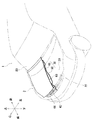
まず、図1〜2を参照して、本発明の実施例1に係る車両1のフロント部を説明する。この車両1のフロント部(図1〜2において、フロントガラス80の下側から前方に張り出す部位)には、エンジン(図示しない)を有するエンジンルーム20を形成するボンネット2が備えられている。このボンネット2には、エンジンルーム20の上部に形成された開口22を左右一対のダンパ(図示しない)を介して開閉できるフード30が取り付けられている。
First, with reference to FIGS. 1-2, the front part of the
ここで、図3〜4を参照して、フード30について詳述すると、このフード30は、アウタカバー40と、このアウタカバー40の内面に接合可能なインナカバー50とから二重に構成されている。このアウタカバー40の先端(前端)には、大気であるエアAを取り込み可能なエア取込口42を有するフロントグリル44が形成されている。一方、このインナカバー50の基端(後端)には、上述したエア取込口42から取り込んだエアAを後述するダクト60を介して排出可能なエア排出口52が形成されている。
Here, the
また、これら両カバー40、50は、上述したように、アウタカバー40の内面にインナカバー50を接合させると、これら両カバー40、50の間に、エア取込口42とエア排出口52とを連通させるダクト60が形成されるように、剛性を有する合成樹脂によって、それぞれ一体成形されている。このダクト60が、特許請求の範囲に記載の「第1のダクト」に相当する。
Further, as described above, when the
両カバー40、50は、このように形成されているため、上述したように、アウタカバー40の内面にインナカバー50を接合させると、ダクト60によって、エア取込口42から取り込んだエアAをエア排出口52から排出できる。
Since both the
このように形成されたダクト60には、エアAの入口側から出口側の方向(エア取込口42からエア排出口52の方向)に沿って絞り部62と拡大部64とが備えられている。これにより、チャンバー効果によって、エア取込口42から取り込んだエアAをダクト60の内部で整流すると共に、その流速を落とすことができる。したがって、この取り込んだエアAから水とゴミを分離できる。
The
また、このようにダクト60が形成されると、すなわち、エアAの入口となるエア取込口42がボンネット2の前方に配置されるように、且つ、エアAの出口となるエア排出口52がボンネット2の後方に配置されるようにダクト60が形成されると、このエア取込口42とエア排出口52との間の距離(図4において、L1)を長くできるため、上述したチャンバー効果(整流)の自由度も確保できる。このようにエア取込口42とエア排出口52との間の距離を長くできると、エア取込口42からエアAと共に入り込んだ水やゴミが後述する空調装置へ入り込むことを抑制できる。
In addition, when the
なお、このエア取込口42とエア排出口52との間の距離(図4において、L1)は、従来技術において、カウル170の距離(図6において、L2)に相当するものである。そのため、従来技術であれば、このカウル170の距離(図6において、L2)を長くできなかった。したがって、ルーバー172からエアaと共に入り込んだ水やゴミが空調装置へ入り込み易いという問題もあった。
Note that the distance between the
なお、これら両カバー40、50の接合は、溶着によって行われている。この溶着は、少なくとも、両カバー40、50の縁を含んだ適宜の箇所(図2において、Yで示す箇所)で行われている。これにより、フード30としての強度も確保できる。フード30は、このように構成されている。
The
また、この車両1のフロント部におけるボデーのうち、フロントガラス80の下側が組み付けられるボデー(以下、「フロントボデー10」と記す)には、車内の空調装置(図示しない)へ送り込むためのエアAを取り込むエア取込口12が形成されている。このフロントボデー10のエア取込口12と上述したフード30のエア排出口52とは、伸縮可能な蛇腹状に形成されたホース70によって接続されている。
Of the bodies at the front portion of the
すなわち、フード30のエア排出口52とホース70の入口70aとが接続され、ホース70の出口70bとフロントボデー10のエア取込口12とが接続されている。これにより、フード30のエア排出口52とフロントボデー10のエア取込口12とは連通するため、フード30のエア排出口52から排出されたエアAをフロントボデー10のエア取込口12へ送ることができる。このホース70が、特許請求の範囲に記載の「第2のダクト」に相当する。
That is, the
なお、ホース70は、上述したように、自身が伸縮可能な蛇腹状に形成されているため、フード30を開閉しても、フード30のエア排出口52とフロントボデー10のエア取込口12との連通は保持されることとなる。車両1のフロント部は、このように構成されている。
As described above, the
本発明の実施例1に係るフード30は、上述したように構成されている。この構成によれば、フード30は、アウタカバー40と、このアウタカバー40の内面に接合されたインナカバー50とから構成されている。これら両カバー40、50は、上述したようにアウタカバー40の内面にインナカバー50を接合させると、これら両カバー40、50の間に、エア取込口42から取り込んだエアAを内部で整流し、この整流したエアAをエア排出口52から排出可能なダクト60が形成されるように構成されている。そして、フード30のエア排出口52とホース70の入口70aとが接続され、ホース70の出口70bとフロントボデー10のエア取込口12とが接続されている。
The
このようにアウタカバー40の内面にインナカバー50を接合させることでダクト60を形成できるため、簡便な構造でダクト60を形成できる。そして、ダクト60を介してフード30のエア取込口42とエア排出口52とを連通させることができると共に、ホース70を介してフード30のエア排出口52とフロントボデー10のエア取込口12とを連通させることができる。そのため、フード30のエア取込口42からエアAを取り込み、この取り込んだエアAをダクト60の内部で整流しホース70を介して、フロントボデー10のエア取込口12へ送ることができる。したがって、従来技術の説明と同様に、簡便な構造で、車外から取り込んだエアAを整流して車内の空調装置へ送り込むことができる。また、従来技術と比較すると、ルーバー172が不要となるため、部品点数の増加を抑えることができる。すなわち、従来技術であれば、フード130、ルーバー172、カウル170の3部品を必要としていたが、本実施例1では、フード30、ホース70の2部品で済ませることができる。
Since the
(実施例2)
次に、本発明の実施例2を、図5を用いて説明する。この実施例2は、既に説明した実施例1と比較すると、フロントグリル44のエア取込口42から取り込んだエアAを、さらに、エンジンルームE1内にも送り込む形態である。なお、以下の説明にあたって、実施例1と同一もしくは均等な構成の部材には、図面において、同一符号を付すことで重複する説明は省略することとする。
(Example 2)
Next, a second embodiment of the present invention will be described with reference to FIG. In the second embodiment, the air A taken in from the
図5に示すように、インナカバー50には、その厚み方向を貫通する開口90が形成されている。この開口90は、インナカバー50のうち、エンジンルームE1内のエンジンE後方域の上部に相当する位置に形成されている。すなわち、この開口90は、エンジンルームE1内においてエンジンEから発せられる熱がこもる熱滞留部Bへ、フロントグリル44のエア取込口42から取り込んだエアAを送り込み可能な位置に形成されている。この開口90の縁には、その開口90を開閉可能となるようにカバー92がヒンジ結合されている。
As shown in FIG. 5, the
このとき、カバー92は、常時、開口90を閉じる方向にトーションばね(図示しない)を介して付勢された状態でヒンジ結合されている。このカバー92は、図5からも明らかなように、風受壁92aを有する略L字状に形成されている。これにより、フロントグリル44のエア取込口42から取り込んだエアAの抵抗面となるため、この抵抗力によってカバー92を確実に開けることができる。
At this time, the
なお、このトーションばねの付勢力は、車両1の停止時には、カバー92が閉じ状態(図5において、カバー92が実線で示された状態)を成すように、また、車両1の走行時には、フロントグリル44のエア取込口42から取り込んだエアAによってカバー92が開き状態(図5において、カバー92が想像線で示された状態)を成すように設定されている。
The urging force of the torsion spring is such that when the
本発明の実施例2に係るフード130は、上述したように構成されている。この構成によれば、実施例1と同様の作用効果を得ることができる。また、この構成によれば、インナカバー50には、エンジンルームE1内においてエンジンEから発せられる熱がこもる熱滞留部Bへ、フロントグリル44のエア取込口42から取り込んだエアAを送り込み可能な位置に開口90が形成されている。そのため、この取り込んだエアAを、空調装置だけでなく、熱滞留部Bにも送ることができる。したがって、図5に示すように、熱滞留部Bにこもっている熱をフード130と板金14との隙間から車両1の外部へ逃がすことができる。なお、図5において、矢印Cが、熱滞留部Bにこもっている熱の逃げを示している。
The
また、この構成によれば、開口90の縁には、その開口90を開閉可能となるように、カバー92が、常時、開口90を閉じる方向にトーションばねを介して付勢された状態でヒンジ結合されている。そのため、車両1の停止時には、エンジンルームE1内の熱が空調装置へ送り込まれることを防止できる。
In addition, according to this configuration, the
上述した内容は、あくまでも本発明の一実施の形態に関するものであって、本発明が上記内容に限定されることを意味するものではない。
各実施例では、『ボンネット2』の例として、『エンジンルーム20』を形成する例を説明した。しかし、これに限定されるものでなく、トランクルームを形成しても構わない。
The contents described above are only related to one embodiment of the present invention, and do not mean that the present invention is limited to the above contents.
In each embodiment, an example in which “
また、各実施例では、フード30のエア排出口52とホース70の入口70aとが接続されている例を説明した。しかし、これに限定されるものでなく、フード30を閉じ状態にすると、フード30のエア排出口52とホース70の入口70aとが連通するように、ホース70の入口70aがフード30のエア排出口52を待ち受けるように、ホース70をフロントボデー10に組み付けても構わない。その場合、ホース70の伸縮機能が不要となる。
In each embodiment, the example in which the
また、各実施例では、両カバー40、50は、剛性を有する合成樹脂によって、それぞれ一体成形されている例を説明した。しかし、これに限定されるものでなく、金属によって、それぞれ一体成形されていても構わない。また、両カバー40、50の一方が、剛性を有する合成樹脂によって、一体成形され、同他方が、金属によって一体成形されていても構わない。
Moreover, in each Example, the both covers 40 and 50 demonstrated the example integrally molded by the synthetic resin which has rigidity, respectively. However, the present invention is not limited to this, and each may be integrally formed of metal. Further, one of the
2 ボンネット
20 エンジンルーム
22 開口
30 フード(実施例1)
40 アウタカバー
42 エア取込口
50 インナカバー(実施例1)
52 エア排出口
60 ダクト(第1のダクト)
70 ホース(第2のダクト)
90 開口
130 フード(実施例2)
150 インナカバー(実施例2)
E エンジン
E1 エンジンルーム
2
40
52
70 hose (second duct)
90
150 Inner cover (Example 2)
E engine E1 engine room
Claims (1)
アウタカバーと、このアウタカバーの内面に接合されたインナカバーとから成る二重構造となっており、
これら両カバーの間には、その先端側に形成されたエア取込口から取り込んだエアを内部で整流し、この整流したエアを基端側に形成されたエア排出口から排出可能な第1のダクトが形成されており、
エア排出口は、ボンネットの開口を閉じ状態にすると、車内の空調装置へエアを送り込み可能な第2のダクトの入口と連通可能に形成されており、
インナカバーには、エンジンルーム内においてエンジンから発せられる熱がこもる熱滞留部へ外気を取り込むための開口が設けられており、
インナカバーには、開口を開閉可能なカバーが付勢部材を介して取り付けられており、
この付勢部材の付勢力は、車両の停止時には、カバーが閉じ状態を成すように、また、車両の走行時には、エア取込口から取り込んだエアによってカバーが開き状態を成すように設定されていることを特徴とするフード。 A hood capable of opening and closing an opening of a hood that forms an engine room or a trunk room,
It has a double structure consisting of an outer cover and an inner cover joined to the inner surface of the outer cover.
Between these two covers, the air taken in from the air intake port formed on the front end side thereof is rectified inside, and the rectified air can be discharged from the air discharge port formed on the base end side. The duct is formed,
The air discharge port is formed so as to be able to communicate with the inlet of the second duct that can send air to the air conditioner in the vehicle when the opening of the bonnet is closed .
The inner cover is provided with an opening for taking outside air into a heat retention part where heat generated from the engine is accumulated in the engine room.
A cover that can open and close the opening is attached to the inner cover via an urging member,
The urging force of the urging member is set so that the cover is closed when the vehicle is stopped, and the cover is opened by air taken in from the air intake port when the vehicle is running. Food, characterized in that there.
Priority Applications (1)
| Application Number | Priority Date | Filing Date | Title |
|---|---|---|---|
| JP2011069614A JP5710333B2 (en) | 2010-09-13 | 2011-03-28 | hood |
Applications Claiming Priority (3)
| Application Number | Priority Date | Filing Date | Title |
|---|---|---|---|
| JP2010203975 | 2010-09-13 | ||
| JP2010203975 | 2010-09-13 | ||
| JP2011069614A JP5710333B2 (en) | 2010-09-13 | 2011-03-28 | hood |
Publications (2)
| Publication Number | Publication Date |
|---|---|
| JP2012081946A JP2012081946A (en) | 2012-04-26 |
| JP5710333B2 true JP5710333B2 (en) | 2015-04-30 |
Family
ID=46241266
Family Applications (1)
| Application Number | Title | Priority Date | Filing Date |
|---|---|---|---|
| JP2011069614A Expired - Fee Related JP5710333B2 (en) | 2010-09-13 | 2011-03-28 | hood |
Country Status (1)
| Country | Link |
|---|---|
| JP (1) | JP5710333B2 (en) |
Families Citing this family (3)
| Publication number | Priority date | Publication date | Assignee | Title |
|---|---|---|---|---|
| CN103434573A (en) * | 2013-08-29 | 2013-12-11 | 丹阳市新威汽车部件有限公司 | Engine face shield for motor vehicle |
| DE102017126766B4 (en) * | 2017-11-14 | 2020-10-08 | Dr. Ing. H.C. F. Porsche Aktiengesellschaft | Vehicle component |
| WO2023233578A1 (en) * | 2022-06-01 | 2023-12-07 | 日産自動車株式会社 | Cool air generating duct structure |
Family Cites Families (3)
| Publication number | Priority date | Publication date | Assignee | Title |
|---|---|---|---|---|
| JPS4813551Y1 (en) * | 1969-04-30 | 1973-04-13 | ||
| JPS58173574U (en) * | 1982-05-17 | 1983-11-19 | 日産自動車株式会社 | Hood structure |
| JPH0194183U (en) * | 1987-12-16 | 1989-06-21 |
-
2011
- 2011-03-28 JP JP2011069614A patent/JP5710333B2/en not_active Expired - Fee Related
Also Published As
| Publication number | Publication date |
|---|---|
| JP2012081946A (en) | 2012-04-26 |
Similar Documents
| Publication | Publication Date | Title |
|---|---|---|
| US9062639B1 (en) | Dual inlet air induction system with panel filter for vehicle engine | |
| JP5817487B2 (en) | Intake device for vehicle engine | |
| TWI379781B (en) | Automotive vehicle having engine air guide passage | |
| US9333849B2 (en) | Co-injected sealing structure of an air recirculation prevention device | |
| JP5710333B2 (en) | hood | |
| JP4569435B2 (en) | Air intake intake structure for vehicle air intake duct | |
| JP6248613B2 (en) | Vehicle lower structure | |
| US9914340B1 (en) | Vehicle cowl attachment | |
| JP2008126797A (en) | Front vehicle body structure for vehicle | |
| EP2205479B1 (en) | Bonnet with integrated air duct | |
| JP3865248B2 (en) | Intake duct of internal combustion engine and vehicle equipped with the intake duct | |
| JP2006335087A (en) | Ventilation structure of vehicle | |
| WO2017086261A1 (en) | Air intake duct | |
| JP6303554B2 (en) | Intake device for vehicle engine | |
| US2864299A (en) | Vehicle ventilator | |
| JP2008189198A (en) | Exhaust port structure | |
| JP6734214B2 (en) | Vehicle front structure | |
| JP6643766B2 (en) | Automotive bonnet structure | |
| JP2020083108A (en) | Front structure of vehicle | |
| JP7313776B2 (en) | vehicle front structure | |
| JP6926937B2 (en) | Intake duct | |
| JP5959802B2 (en) | Cowl louver | |
| JPS625368Y2 (en) | ||
| JP2017074836A (en) | Vehicle ventilation structure | |
| TR201617223A2 (en) | AN AIR DISTRIBUTION PANEL FOR VEHICLES |
Legal Events
| Date | Code | Title | Description |
|---|---|---|---|
| A621 | Written request for application examination |
Free format text: JAPANESE INTERMEDIATE CODE: A621 Effective date: 20131025 |
|
| A131 | Notification of reasons for refusal |
Free format text: JAPANESE INTERMEDIATE CODE: A131 Effective date: 20140729 |
|
| A977 | Report on retrieval |
Free format text: JAPANESE INTERMEDIATE CODE: A971007 Effective date: 20140730 |
|
| A521 | Written amendment |
Free format text: JAPANESE INTERMEDIATE CODE: A523 Effective date: 20140929 |
|
| TRDD | Decision of grant or rejection written | ||
| A01 | Written decision to grant a patent or to grant a registration (utility model) |
Free format text: JAPANESE INTERMEDIATE CODE: A01 Effective date: 20150303 |
|
| A61 | First payment of annual fees (during grant procedure) |
Free format text: JAPANESE INTERMEDIATE CODE: A61 Effective date: 20150304 |
|
| R150 | Certificate of patent or registration of utility model |
Ref document number: 5710333 Country of ref document: JP Free format text: JAPANESE INTERMEDIATE CODE: R150 |
|
| LAPS | Cancellation because of no payment of annual fees |