JP5708542B2 - Nozzle plate manufacturing method - Google Patents
Nozzle plate manufacturing method Download PDFInfo
- Publication number
- JP5708542B2 JP5708542B2 JP2012073014A JP2012073014A JP5708542B2 JP 5708542 B2 JP5708542 B2 JP 5708542B2 JP 2012073014 A JP2012073014 A JP 2012073014A JP 2012073014 A JP2012073014 A JP 2012073014A JP 5708542 B2 JP5708542 B2 JP 5708542B2
- Authority
- JP
- Japan
- Prior art keywords
- repellent film
- water repellent
- film
- water
- nozzle
- Prior art date
- Legal status (The legal status is an assumption and is not a legal conclusion. Google has not performed a legal analysis and makes no representation as to the accuracy of the status listed.)
- Expired - Fee Related
Links
Images


Description
本発明は、ノズル孔が形成されるノズル基板の表面に撥水膜を有するノズルプレートの製造方法に関するものである。 The present invention relates to a method for manufacturing a nozzle plate having a water repellent film on the surface of a nozzle substrate on which nozzle holes are formed.
インクジェットヘッドのノズル孔から吐出されるインク滴の直進安定性を上げるためには、ノズル孔が形成されたノズル基板の表面に撥水膜(撥インク膜)が均一にコートされ、撥水膜がノズル孔の内部(特に内面)に入り込まないようにすることが重要である。しかし、撥水膜の形成にディップコート、スピンコート、蒸着等を用いた場合、ノズル孔の内部への撥水膜の回り込みが避けられない。 In order to improve the straight running stability of the ink droplets ejected from the nozzle holes of the ink jet head, a water repellent film (ink repellent film) is uniformly coated on the surface of the nozzle substrate on which the nozzle holes are formed. It is important not to get inside the nozzle hole (especially the inner surface). However, when dip coating, spin coating, vapor deposition, or the like is used to form the water repellent film, it is inevitable that the water repellent film wraps around the nozzle holes.
ノズル孔の内部に回り込んだ撥水膜は、通常、アッシング処理によって除去される。このアッシング処理とは、酸素ガスをプラズマ化した酸素プラズマや、波長300nm以下の遠紫外線(Deep UV)照射により生成される酸素ラジカルによって、不要な撥水膜を除去する処理を言う。このとき、ノズル基板の表面(ノズル孔以外の部分)に塗布された撥水膜へのダメージを低減するため、ノズル基板の上記表面側(吐出面側)にマスク材を形成した状態で、ノズル基板に対してマスク材とは反対側から、上記のアッシング処理によって不要な撥水膜が除去される。 The water repellent film that has entered the inside of the nozzle hole is usually removed by ashing. The ashing process is a process of removing an unnecessary water repellent film by oxygen plasma generated by converting oxygen gas into plasma or oxygen radicals generated by irradiation with deep ultraviolet rays having a wavelength of 300 nm or less. At this time, in order to reduce damage to the water repellent film applied to the surface of the nozzle substrate (portion other than the nozzle holes), the nozzle is formed with a mask material formed on the surface side (discharge surface side) of the nozzle substrate. An unnecessary water-repellent film is removed from the side opposite to the mask material with respect to the substrate by the ashing process.
例えば、特許文献1では、ノズル基板の表面およびノズル孔の内面に撥水膜を形成し、ノズル基板の表面側およびノズル孔内面の所定深さまで感光性樹脂によりマスクを施し、プラズマ処理によって、マスクされた部分以外の撥水膜を除去するようにしている。
For example, in
ところが、ノズル孔の内面の不要な撥水膜をアッシング処理によって除去する場合、ノズル孔を小径化(微細化)するほど、ノズル孔の内面への反応種(酸素活性種)の到達が困難となるため、その除去には、通常、長時間を要する。このような、不要な撥水膜を除去するための長時間のアッシング処理は、ノズル孔の周辺の撥水膜にもダメージを与えることになる。その結果、撥水膜の撥インク性(インクをはじく性質)が低下するため、ノズル孔から吐出される液滴(例えばインク滴)の直進安定性を向上させることができないという問題が生ずる。 However, when the unnecessary water-repellent film on the inner surface of the nozzle hole is removed by ashing, it is difficult to reach the reactive species (oxygen-activated species) on the inner surface of the nozzle hole as the diameter of the nozzle hole is reduced (miniaturized). Therefore, the removal usually requires a long time. Such a long-time ashing treatment for removing the unnecessary water-repellent film also damages the water-repellent film around the nozzle holes. As a result, the ink repellency (property of ink repelling) of the water repellent film is lowered, so that there is a problem that the straight running stability of the droplets (for example, ink droplets) ejected from the nozzle holes cannot be improved.
本発明は、上記の問題点を解決するためになされたもので、その目的は、アッシング処理に要する時間を短縮して、ノズル孔の周辺の撥水膜へのダメージを低減することができ、これによって、撥水膜の撥インク性の低下を回避して、ノズル孔から吐出される液滴の直進安定性を向上させることができるノズルプレートの製造方法を提供することにある。 The present invention was made in order to solve the above problems, and its purpose is to shorten the time required for the ashing process and to reduce damage to the water-repellent film around the nozzle hole, Accordingly, it is an object of the present invention to provide a method for manufacturing a nozzle plate that can prevent a drop in ink repellency of a water-repellent film and improve the straight-running stability of droplets ejected from nozzle holes.
本発明のノズルプレートの製造方法は、ノズル孔が形成されるノズル基板の表面に撥水膜を有するノズルプレートの製造方法であって、ベースフィルム上に撥水剤を塗布し、前記撥水剤を加熱して固化することにより、撥水膜を形成する撥水膜形成工程と、前記撥水膜を介して前記ベースフィルムを前記ノズル基板に押圧して貼り合せる貼付工程と、前記撥水膜における、前記ノズル基板の前記ノズル孔と対向する領域を、酸素プラズマまたは遠紫外線照射によって除去するアッシング工程と、前記アッシング工程の後、前記ベースフィルムを前記撥水膜から剥離する剥離工程とを有していることを特徴としている。 The method for producing a nozzle plate of the present invention is a method for producing a nozzle plate having a water-repellent film on the surface of a nozzle substrate on which nozzle holes are formed, wherein a water-repellent agent is applied onto a base film, A water repellent film forming step of forming a water repellent film by heating and solidifying, a sticking step of pressing and bonding the base film to the nozzle substrate via the water repellent film, and the water repellent film An ashing step of removing the region of the nozzle substrate facing the nozzle hole by irradiation with oxygen plasma or deep ultraviolet radiation, and a peeling step of peeling the base film from the water-repellent film after the ashing step. It is characterized by that.
ベースフィルム側からノズル基板側に固体状の撥水膜を転写する方式を採用することにより、ノズル基板のノズル孔内に撥水膜が入り込むのを回避しながら、ノズル基板の表面に撥水膜を付けることができる。これにより、不要な撥水膜を、酸素プラズマまたは遠紫外線照射によって除去するアッシングを行うにあたって、撥水膜においてノズル孔と対向する領域を除去するだけで済む(ノズル孔の側面に付着した撥水膜を除去する工程が不要となる)。したがって、ノズル孔を小径化(微細化)する場合でも、アッシング処理全体の時間を短縮して、ノズル孔の周辺の撥水膜へのダメージを低減することができる。その結果、撥水膜の撥インク性の低下を回避して、ノズルプレートのノズル孔から吐出される液滴(例えばインク滴)の直進安定性を向上させることができる。 By adopting a method of transferring a solid water-repellent film from the base film side to the nozzle substrate side, the water-repellent film on the surface of the nozzle substrate while avoiding the water-repellent film entering the nozzle holes of the nozzle substrate Can be attached. Thus, when performing ashing to remove unnecessary water repellent film by oxygen plasma or far ultraviolet irradiation, it is only necessary to remove a region facing the nozzle hole in the water repellent film (water repellent adhering to the side surface of the nozzle hole). The process of removing the film is unnecessary). Therefore, even when the diameter of the nozzle hole is reduced (miniaturized), it is possible to reduce the time for the entire ashing process and reduce damage to the water-repellent film around the nozzle hole. As a result, it is possible to avoid a decrease in ink repellency of the water repellent film and to improve the straight running stability of droplets (for example, ink droplets) ejected from the nozzle holes of the nozzle plate.
前記撥水膜形成工程では、ETFEからなる前記ベースフィルム上に、前記撥水膜として、前記ノズル基板との接着のための官能基を持つフッ素樹脂からなる撥水膜を形成してもよい。 In the water repellent film forming step, a water repellent film made of a fluororesin having a functional group for adhesion to the nozzle substrate may be formed on the base film made of ETFE as the water repellent film.
ベースフィルムを構成するETFEは、撥水膜を構成するフッ素樹脂との親和性が低いので、剥離工程にてベースフィルムを剥離する際に、撥水膜からベースフィルムを容易に剥離することが可能となる。また、撥水膜は、ノズル基板との接着のための官能基を持っているので、撥水膜とノズル基板との高い接着性を確保することができる。 Since ETFE constituting the base film has low affinity with the fluororesin constituting the water repellent film, it is possible to easily peel the base film from the water repellent film when peeling the base film in the peeling process. It becomes. Further, since the water repellent film has a functional group for adhesion to the nozzle substrate, high adhesion between the water repellent film and the nozzle substrate can be ensured.
前記撥水膜として、末端官能基がCOOHであるアモルファスフッ素樹脂にシランカップリング剤を予め反応させた樹脂を用いてもよい。 As the water repellent film, a resin obtained by previously reacting an amorphous fluororesin having a terminal functional group of COOH with a silane coupling agent may be used.
末端官能基がCOOH(カルボキシル基)であるアモルファスフッ素樹脂にシランカップリング剤を反応させると、上記のカルボキシル基が、シランカップリング剤のアミノ基との間で脱水縮合反応を起こし、これによって、CONH〜Si(OR)nを官能基として持つ撥水膜が生成される。上記の官能基は、撥水膜とノズル基板とを共有結合によって結びつける機能を持つため、撥水膜とノズル基板との高い接着性を確実に確保することができる。また、カルボキシル基は、ノズル基板と水素結合により結びつくことができるため、カルボキシル基がアミノ基と反応せずに残存していても、撥水膜とノズル基板との高い接着性を確保することができる。 When an amorphous fluororesin having a terminal functional group of COOH (carboxyl group) is reacted with a silane coupling agent, the above carboxyl group causes a dehydration condensation reaction with the amino group of the silane coupling agent, A water repellent film having CONH to Si (OR) n as a functional group is generated. Since the functional group has a function of binding the water-repellent film and the nozzle substrate by a covalent bond, high adhesion between the water-repellent film and the nozzle substrate can be reliably ensured. In addition, since the carboxyl group can be bonded to the nozzle substrate by hydrogen bonding, high adhesion between the water repellent film and the nozzle substrate can be ensured even if the carboxyl group remains without reacting with the amino group. it can.
上記製造方法は、前記ベースフィルム上に前記撥水膜を形成した後、前記撥水膜上にシランカップリング剤を塗布するシラン処理工程をさらに有していてもよい。 The manufacturing method may further include a silane treatment step of applying a silane coupling agent on the water repellent film after forming the water repellent film on the base film.
この場合、撥水膜においてカルボキシル基が残存していても、シランカップリング剤の塗布によって新たに官能基(CONH〜Si(OR)n)を生成し、この官能基によって、撥水膜とノズル基板との接着性をさらに強化することができる。 In this case, even if a carboxyl group remains in the water repellent film, a new functional group (CONH to Si (OR) n) is generated by application of the silane coupling agent, and the water repellent film and the nozzle are formed by this functional group. Adhesiveness with the substrate can be further enhanced.
前記撥水膜形成工程では、前記ベースフィルム上に、前記撥水膜として、前記ベースフィルムとの接着のための官能基を持たない第1の撥水膜と、前記ノズル基板との接着のための官能基を持つ第2の撥水膜とをこの順で形成してもよい。 In the water repellent film forming step, the first water repellent film having no functional group for adhesion to the base film as the water repellent film on the base film and the nozzle substrate are adhered. The second water-repellent film having the functional group may be formed in this order.
第1の撥水膜は、ベースフィルムとの接着のための官能基を持っていないので、剥離工程にてベースフィルムを剥離する際に、第1の撥水膜からベースフィルムを容易に剥離することが可能となる。また、第2の撥水膜は、ノズル基板との接着のための官能基を持っているので、第2の撥水膜とノズル基板との高い接着性を確保することができる。 Since the first water repellent film does not have a functional group for adhesion to the base film, the base film is easily peeled off from the first water repellent film when the base film is peeled off in the peeling step. It becomes possible. Further, since the second water repellent film has a functional group for adhesion to the nozzle substrate, high adhesion between the second water repellent film and the nozzle substrate can be ensured.
前記第1の撥水膜として、末端官能基がCF3であるアモルファスフッ素樹脂を用いてもよい。 As the first water repellent film, an amorphous fluororesin having a terminal functional group of CF 3 may be used.
末端官能基がCF3(トリフルオロメチル基)であるアモルファスフッ素樹脂は、他の部材との接着性を有しておらず、ベースフィルムとの接着のための官能基を持たない樹脂を構成できるため、第1の撥水膜として非常に有効となる。 The amorphous fluororesin whose terminal functional group is CF 3 (trifluoromethyl group) does not have adhesiveness to other members, and can constitute a resin having no functional group for adhesion to the base film. Therefore, it is very effective as the first water repellent film.
前記第2の撥水膜として、末端官能基がCOOHであるアモルファスフッ素樹脂にシランカップリング剤を予め反応させた樹脂を用いてもよい。 As the second water repellent film, a resin obtained by previously reacting an amorphous fluororesin having a terminal functional group of COOH with a silane coupling agent may be used.
末端官能基がCOOH(カルボキシル基)であるアモルファスフッ素樹脂にシランカップリング剤を反応させると、上記のカルボキシル基が、シランカップリング剤のアミノ基との間で脱水縮合反応を起こし、これによって、CONH〜Si(OR)nを官能基として持つ撥水膜が生成される。上記の官能基は、第2の撥水膜とノズル基板とを共有結合によって結びつける機能を持つため、第2の撥水膜とノズル基板との高い接着性を確実に確保することができる。また、カルボキシル基は、ノズル基板と水素結合により結びつくことができるため、カルボキシル基がアミノ基と反応せずに残存していても、第2の撥水膜とノズル基板との高い接着性を確保することができる。 When an amorphous fluororesin having a terminal functional group of COOH (carboxyl group) is reacted with a silane coupling agent, the above carboxyl group causes a dehydration condensation reaction with the amino group of the silane coupling agent, A water repellent film having CONH to Si (OR) n as a functional group is generated. Since the functional group has a function of binding the second water-repellent film and the nozzle substrate by a covalent bond, it is possible to ensure high adhesion between the second water-repellent film and the nozzle substrate. In addition, since the carboxyl group can be bonded to the nozzle substrate by hydrogen bonding, high adhesion between the second water-repellent film and the nozzle substrate is ensured even if the carboxyl group remains without reacting with the amino group. can do.
上記製造方法は、前記ベースフィルム上に前記第2の撥水膜を形成した後、前記第2の撥水膜上にシランカップリング剤を塗布するシラン処理工程をさらに有していてもよい。 The manufacturing method may further include a silane treatment step of applying a silane coupling agent on the second water-repellent film after forming the second water-repellent film on the base film.
この場合、第2の撥水膜においてカルボキシル基が残存していても、シランカップリング剤の塗布によって新たに官能基(CONH〜Si(OR)n)を生成し、この官能基によって、第2の撥水膜とノズル基板との接着性をさらに強化することができる。 In this case, even if a carboxyl group remains in the second water repellent film, a new functional group (CONH to Si (OR) n) is generated by application of the silane coupling agent, and the second The adhesion between the water repellent film and the nozzle substrate can be further enhanced.
前記貼付工程の前に、前記ノズル基板における前記ベースフィルムの貼付側の表面を、酸素プラズマまたは遠紫外線照射によって活性化する活性化工程をさらに有していてもよい。 Before the sticking step, an activation step of activating the surface on the sticking side of the base film on the nozzle substrate by irradiation with oxygen plasma or far ultraviolet rays may be further included.
ノズル基板の表面を活性化することにより、ノズル基板の表面に現れる水酸基が、撥水膜の官能基と化学結合するため、撥水膜とノズル基板との接着性をさらに強化することができる。 By activating the surface of the nozzle substrate, the hydroxyl group appearing on the surface of the nozzle substrate chemically bonds with the functional group of the water-repellent film, so that the adhesion between the water-repellent film and the nozzle substrate can be further enhanced.
上記製造方法は、前記貼付工程の前に、前記ノズル基板における前記ベースフィルムの貼付側の表面を、酸素プラズマまたは遠紫外線照射によって活性化する活性化工程と、前記貼付工程の前に、前記ノズル基板における前記ベースフィルムの貼付側の表面にシランカップリング剤を塗布する塗布工程とをさらに有しており、前記撥水膜形成工程では、前記撥水膜として、末端官能基がCOOHであるアモルファスフッ素樹脂を用いてもよい。 The manufacturing method includes an activation step of activating the surface of the base film on the nozzle substrate on the side of the base film by oxygen plasma or far ultraviolet irradiation before the pasting step, and the nozzle before the pasting step. And an application step of applying a silane coupling agent to the surface of the base film on the substrate on which the base film is applied. In the water-repellent film forming step, an amorphous whose terminal functional group is COOH is used as the water-repellent film. A fluororesin may be used.
ノズル基板の表面の活性化により現れる水酸基が、シランカップリング剤の官能基と反応して化学結合するとともに、シランカップリング剤のアミノ基が、撥水膜のカルボキシル基と反応してアミド結合する。これにより、撥水膜とノズル基板との接着性をさらに強化することができる。 The hydroxyl group that appears due to the activation of the surface of the nozzle substrate reacts with the functional group of the silane coupling agent to chemically bond, and the amino group of the silane coupling agent reacts with the carboxyl group of the water-repellent film to form an amide bond. . Thereby, the adhesiveness between the water repellent film and the nozzle substrate can be further enhanced.
上述した製造方法によれば、ノズル基板のノズル孔内に撥水膜が入り込むのを回避しながら、ノズル基板の表面に撥水膜を付けることができるので、ノズル孔の側面に付着した撥水膜をアッシングによって除去する工程が不要となる。これにより、ノズル孔を小径化する場合でも、アッシング処理全体の時間を短縮して、ノズル孔の周辺の撥水膜へのダメージを低減することができる。その結果、撥水膜の撥インク性の低下を回避して、ノズルプレートのノズル孔から吐出される液滴の直進安定性を向上させることができる。 According to the manufacturing method described above, the water-repellent film can be attached to the surface of the nozzle substrate while avoiding the water-repellent film from entering the nozzle holes of the nozzle substrate. A step of removing the film by ashing is not necessary. Thereby, even when the diameter of the nozzle hole is reduced, the time for the entire ashing process can be shortened and damage to the water repellent film around the nozzle hole can be reduced. As a result, it is possible to avoid a drop in the ink repellency of the water repellent film and improve the straight-running stability of the droplets ejected from the nozzle holes of the nozzle plate.
〔実施の形態1〕
本発明の実施の一形態について、図面に基づいて説明すれば、以下の通りである。
[Embodiment 1]
An embodiment of the present invention will be described below with reference to the drawings.
図1は、本実施形態のノズルプレートの製造に用いる撥水膜の末端官能基以外の構造式を示している。なお、nは構造の繰り返し単位の数を示している。撥水膜は、上記の構造式を持つアモルファスフッ素樹脂で構成されている。このようなアモルファスフッ素樹脂としては、例えば旭硝子株式会社製のCYTOP(登録商標)を用いることができる。 FIG. 1 shows a structural formula other than the terminal functional group of the water-repellent film used for manufacturing the nozzle plate of this embodiment. Note that n represents the number of repeating units of the structure. The water repellent film is made of an amorphous fluororesin having the above structural formula. As such an amorphous fluororesin, for example, CYTOP (registered trademark) manufactured by Asahi Glass Co., Ltd. can be used.
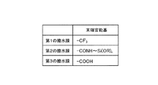
図2は、上記のアモルファスフッ素樹脂からなる撥水膜の種類を示している。同図に示すように、撥水膜は、末端官能基の種類によって、第1〜第3の撥水膜に分類される。第1の撥水膜は、末端官能基としてCF3(トリフルオロメチル基)を有するアモルファスフッ素樹脂である。第2の撥水膜は、末端官能基として、CONH〜Si(OR)nを有するアモルファスフッ素樹脂である。なお、Rはアルキル基を示し、例えば−H、−CH3、−CH2−CH3、−CH2−CH2−CH3などである。第3の撥水膜は、末端官能基として、COOH(カルボキシル基)を有するアモルファスフッ素樹脂である。 FIG. 2 shows types of water-repellent films made of the above amorphous fluororesin. As shown in the figure, the water repellent film is classified into first to third water repellent films depending on the type of the terminal functional group. The first water repellent film is an amorphous fluororesin having CF 3 (trifluoromethyl group) as a terminal functional group. The second water repellent film is an amorphous fluororesin having CONH to Si (OR) n as a terminal functional group. Incidentally, R represents an alkyl group, for example -H, -CH 3, -CH 2 -CH 3, and the like -CH 2 -CH 2 -CH 3. The third water repellent film is an amorphous fluororesin having COOH (carboxyl group) as a terminal functional group.
このうち、第2および第3の撥水膜の末端官能基は、後述するノズル基板21(図3参照)との接着性を持っているのに対して、第1の撥水膜の末端官能基は、ノズル基板21との接着性を持っていない。本実施形態では、例として、ノズル基板21との接着のための官能基を持つ第2の撥水膜を用いてノズルプレートを製造する場合について説明する。なお、以下での説明の便宜上、第1〜第3の撥水膜を、それぞれ、第1の撥水膜12a、第2の撥水膜12b、第3の撥水膜12cとし、これらをまとめて撥水膜12と称する。
Among these, the terminal functional groups of the second and third water-repellent films have adhesiveness with a nozzle substrate 21 (see FIG. 3) described later, whereas the terminal functional groups of the first water-repellent film. The base does not have adhesiveness with the
図3は、本実施形態のノズルプレート1の製造方法による各製造工程をまとめて示し、図4〜図6は、各製造工程を分けて示している。まず、例えばフッ素系の樹脂であるETFE(テトラフルオロエチレン(C2F4)とエチレン(C2H4)との共重合体)からなるベースフィルム11を、転写用のベースフィルム11として用意する。そして、このベースフィルム11上に、撥水膜12(第2の撥水膜12b)を形成する(撥水膜形成工程)。より具体的には、ベースフィルム11上に撥水剤(液体)をスピンコートまたはディップコート等により塗布して50〜1000nmの膜厚で形成し、この撥水剤を50℃で2〜10分間加熱(プリベーク)して固化することにより、固体状の撥水膜12を形成する。図4は、ベースフィルム11上での撥水膜12の分子構造を模式的に示している。
FIG. 3 shows each manufacturing process by the manufacturing method of the
一方、Siからなるノズル基板21には、インク滴を吐出するためのノズル孔として、直径の異なる2段孔のノズル孔21aを複数並べて形成しておくとともに、ノズル基板21の表面に予め活性化処理を行っておく(活性化工程)。この活性化処理は、ノズル基板21におけるベースフィルム11の貼付側の表面を、酸素プラズマまたは遠紫外線照射によって活性化する処理である。この活性化処理により、図5に示すように、ノズル基板21の表面に水酸基(OH基)が、活性化処理前よりも多く出現する。
On the other hand, on the
次に、撥水膜12を介して、上記のベースフィルム11をノズル基板21に押圧して貼り合せる(貼付工程)。より具体的には、上記のベースフィルム11を、撥水膜12側をノズル基板21と対向させて重ね合わせ、120〜300℃の温度で0.5〜1kgf/cm2の荷重で押圧することにより、撥水膜12が形成されたベースフィルム11とノズル基板21とを接合する。このとき、撥水膜12を形成するフッ素化合物分子の末端には、上述した官能基(CONH〜Si(OR)n)があり、これがノズル基板21の表面の水酸基と容易に反応して、化学結合(例えば共有結合)する(図5参照)。
Next, the
続いて、撥水膜12における、ノズル基板21のノズル孔21aと対向する領域12pを、酸素プラズマまたは遠紫外線照射によって除去する(アッシング工程)。図7は、酸素プラズマまたは遠紫外線照射によって、撥水膜12の不要部分(領域12p)が除去される様子を模式的に示している。このように、酸素プラズマまたは遠紫外線照射により生成される酸素活性種(イオン種、ラジカル種)が、撥水膜12を構成している分子の結合を切ってガス化することで、撥水膜12の領域12pが除去される。このとき、撥水膜12におけるノズル基板21とは反対側にはベースフィルム11が付着しているため、撥水膜12の領域12pは、ノズル孔21a側からベースフィルム11側に向かって削られていき、除去される。
Subsequently, the
なお、酸素活性種としてのイオン種は、電圧を印加して除去しようとする部分にイオンを衝突させ、その部分の原子を物理的に弾き飛ばす。また、ラジカル種は、除去しようとする部分の有機物と反応(例えば酸化)し、二酸化炭素や水を生成する。したがって、このようなイオン種およびラジカル種を含む酸素活性種を発生させることにより、不要な撥水膜12を除去することができる。
Note that the ion species as the oxygen active species cause ions to collide with a portion to be removed by applying a voltage, and physically blow off atoms in the portion. In addition, the radical species react (for example, oxidize) with the organic substance in the portion to be removed, and generate carbon dioxide and water. Therefore, unnecessary
上記したアッシング工程の後、ベースフィルム11を撥水膜12から剥離する(剥離工程)。これにより、ノズル基板21の表面に撥水膜12が転写された状態となる。このとき、上述したように、撥水膜12の末端官能基とノズル基板21の水酸基とが反応することで、撥水膜12とノズル基板21との間には化学結合が存在するが、撥水膜12とベースフィルム11との間には化学結合が存在しない。したがって、撥水膜12とノズル基板21との接着力は、撥水膜12とベースフィルム11との接着力よりも確実に大きくなり、このような接着力の差により、ベースフィルム11を撥水膜12から剥離することが可能となる(図6参照)。
After the above ashing step, the
以上のように、本実施形態では、ノズル基板21の表面に撥水膜12を形成するにあたって、撥水膜12を、一旦、ベースフィルム11上に形成しておき、ベースフィルム11側からノズル基板21側に撥水膜12を転写するようにしている。転写される撥水膜12は、固体状の膜であるので、その転写時に、ノズル基板21のノズル孔21a内に撥水膜12が入り込むことはない。つまり、撥水膜12がノズル孔21a内に入り込むのを回避しながら、ノズル基板21の表面に撥水膜12を付けることができる。このように、ノズル孔21aの側面に撥水膜12が入り込むことがないので、上記側面に付着した撥水膜をアッシングによって除去するといった工程も当然不要となる。
As described above, in this embodiment, when the
したがって、ノズル孔21aを小径化(微細化)する場合でも、アッシング処理全体の時間を短縮することができ、これによって、ノズル孔21aの周辺の撥水膜12へのダメージを低減することができる。その結果、撥水膜12の撥インク性の低下を回避して、ノズル孔21aから吐出されるインク滴の直進安定性を向上させることができる。
Therefore, even when the diameter of the
また、ベースフィルム11側とノズル基板21側とで同時に(並行して)処理を行うことができるため、ノズルプレート1の量産性も向上する。
Moreover, since the process can be performed simultaneously (in parallel) on the
また、本実施形態では、従来のような感光性樹脂を用いずにアッシング処理しているので、感光性樹脂の塗布のバラツキや、アッシング処理による感光性樹脂の劣化などを全く考慮する必要がない。その結果、感光性樹脂の塗布バラツキ等に起因して、インク滴の液滴速度が不安定になったり、直進性が低下するのを回避することができる。 Further, in this embodiment, since ashing is performed without using a conventional photosensitive resin, there is no need to take into consideration variations in the application of the photosensitive resin or deterioration of the photosensitive resin due to the ashing. . As a result, it is possible to prevent the ink droplet speed from becoming unstable or the straightness from being deteriorated due to variations in the application of the photosensitive resin.
また、撥水膜形成工程では、ETFEからなるベースフィルム11上に、ノズル基板21との接着のための官能基を持つフッ素樹脂からなる撥水膜12(第2の撥水膜12b)を形成している。ETFEは、撥水膜12を構成するフッ素樹脂との親和性が低いので、剥離工程にてベースフィルム11を剥離する際に、撥水膜12からベースフィルム11を容易に剥離することができる。
In the water repellent film forming step, a water repellent film 12 (second
また、撥水膜12は、ノズル基板21との接着のための官能基を持っているので、撥水膜12とノズル基板21との高い接着性を確保することができる。特に、撥水膜12として、末端官能基がCONH〜Si(OR)nであるアモルファスフッ素樹脂(第2の撥水膜12b)を用いることにより、撥水膜12とノズル基板21とを共有結合によって結びつけることができ、これらの高い接着性を確実に確保することができる。
Moreover, since the
また、第2の撥水膜12bは、末端官能基がCOOHであるアモルファスフッ素樹脂(第3の撥水膜13c)にシランカップリング剤を予め反応させた樹脂であるが(この点の詳細については実施の形態3で説明する)、上記のカルボキシル基(COOH)は、ノズル基板21と水素結合によって結びつくため、撥水膜12においてカルボキシル基がシランカップリング剤と反応せずに残存していても、撥水膜12とノズル基板21との高い接着性を確保することができる。
The second water-
また、ベースフィルム11をノズル基板21に貼り合わせる前に、ノズル基板21におけるベースフィルム11の貼付側の表面を、酸素プラズマまたはUV照射によって活性化するので、上記したように、ノズル基板21の表面に現れる水酸基が、撥水膜12の官能基と化学結合し、これによって、撥水膜12とノズル基板21との接着性をさらに強化することができる。
Further, before the
なお、不要な撥水膜12(領域12p)をアッシング処理によって除去するにあたって、酸素プラズマを用いるほうが、UV照射を用いるよりも処理速度が速いため、アッシング処理での撥水膜12へのダメージを低減する観点からは、酸素プラズマを用いるほうがより望ましい。
In removing the unnecessary water repellent film 12 (
〔実施の形態2〕
本発明の他の実施の形態について、図面に基づいて説明すれば、以下の通りである。
[Embodiment 2]
The following will describe another embodiment of the present invention with reference to the drawings.
前述の実施の形態1では、ベースフィルム11上に撥水膜12を1層のみ形成して、その撥水膜12をノズル基板21側に転写するようにしたが、本実施形態では、ベースフィルム11上に撥水膜12を2層形成して、その2層の撥水膜12をノズル基板21側に転写する例について説明する。
In the first embodiment described above, only one layer of the water-
図8〜図10は、本実施形態のノズルプレート1の製造方法による各製造工程を分けて示している。本実施形態では、図8に示すように、撥水膜形成工程において、ベースフィルム11上に、撥水膜12として、ベースフィルム11との接着のための官能基を持たない第1の撥水膜12aと、ノズル基板21との接着のための官能基(例えばCONH〜Si(OR)n)を持つ第2の撥水膜12bとをこの順で形成する。なお、撥水膜12を2層形成する場合は、それぞれの撥水膜12の形成ごとに、撥水剤(液体)の塗布と加熱による固化とを行えばよい。その後は、図9および図10に示すように、実施の形態1と同様の工程、つまり、ベースフィルム11のノズル基板21への貼付工程、不要な撥水膜12を除去するアッシング工程、ベースフィルム11の剥離工程を行う。
8 to 10 separately show each manufacturing process according to the manufacturing method of the
第1の撥水膜12aは、ベースフィルム11との接着のための官能基を持っていないため、このような第1の撥水膜12aをベースフィルム11上に形成することにより、剥離工程にてベースフィルム11を剥離する際に、第1の撥水膜12aからベースフィルムを容易に剥離することが可能となる。
Since the first
特に、末端官能基がCF3であるアモルファスフッ素樹脂は、他の部材との接着性を有しておらず、ベースフィルムとの接着のための官能基を持たない樹脂を構成できるため、第1の撥水膜12aとして非常に有効となる。つまり、第1の撥水膜12aとして、末端官能基がCF3であるアモルファスフッ素樹脂を用いることにより、剥離工程でのベースフィルム11の剥離が確実に容易となる。
In particular, an amorphous fluororesin having a terminal functional group of CF 3 does not have adhesiveness to other members, and can form a resin having no functional group for adhesion to the base film. The
また、第2の撥水膜12bは、ノズル基板21との接着のための官能基を持っているので、第2の撥水膜12bとノズル基板21との高い接着性を確保することができる。特に、第2の撥水膜12として、末端官能基がCONH〜Si(OR)nであるアモルファスフッ素樹脂を用いることにより、撥水膜12とノズル基板21との高い接着性を確実に確保することができる。
In addition, since the second
なお、第1の撥水膜12aは、ベースフィルム11との接着のための官能基を持っていないが、これでも、ベースフィルム11上に付着させることができるのは、アンカー効果によるものと考えられる。すなわち、例えばベースフィルム11の表面にUV照射を行って、ベースフィルム11の表面に微細な凹凸を形成しておけば、接着面積が増大するため、第1の撥水膜12aとベースフィルム11との間にある程度の接着力を生じさせることができる。これにより、ベースフィルム11上に第1の撥水膜12aを付着させることができる。
Although the first
このように、第1の撥水膜12aが、ベースフィルム11との接着のための官能基を持っていなくても、ベースフィルム11上に第1の撥水膜12aを付着させることができるので、少なくともアッシング工程の終了までは、ベースフィルム11を撥水膜12に付着させておいて、アッシング処理時に、ノズル基板21の表面の撥水膜12にダメージが付与されるのを抑えることができる。
Thus, even if the first
〔実施の形態3〕
本発明のさらに他の実施の形態について、図面に基づいて説明すれば、以下の通りである。
[Embodiment 3]
The following will describe still another embodiment of the present invention with reference to the drawings.
図11は、本実施形態のノズルプレート1の製造方法における一部の製造工程(撥水膜形成工程)を示し、図12は、上記製造方法における他の製造工程(シラン処理工程)を示している。また、図13は、撥水膜12の生成に関する化学反応式と併せて、撥水膜12とノズル基板21との化学結合の様子を模式的に示している。
FIG. 11 shows a part of the manufacturing process (water repellent film forming process) in the manufacturing method of the
実施の形態1および2のように、撥水膜12として、第2の撥水膜12bを用いる場合においては、ベースフィルム11上に第1の撥水膜12aを介して、または直接、第2の撥水膜12bを形成した後、第2の撥水膜12b上にシランカップリング剤を塗布するシラン処理工程をさらに行うようにしてもよい。ここでは、例として、実施の形態2で示した製造方法にシラン処理を適用した場合について説明する。
When the second water-
第2の撥水膜12bは、予め、第3の撥水膜12cにシランカップリング剤を反応させて生成されるものである。つまり、図13に示すように、第3の撥水膜12cにシランカップリング剤を反応させると、第3の撥水膜12cのカルボキシル基(COOH)と、シランカップリング剤(Si(OR)3−(CH2)n−NH2)のアミノ基(NH2)とが脱水縮合反応を起こし、これによって、(CONH〜Si(OR)n)を官能基として持つ撥水膜、すなわち、第2の撥水膜12bが生成される。このとき、第3の撥水膜12cにおいて、全てのカルボキシル基がシランカップリング剤と反応するわけではなく、未反応なカルボキシル基もある程度残存する(図11参照)。
The second
そこで、ベースフィルム11上に第2の撥水膜12bを形成した後、第2の撥水膜12b上にさらにシランカップリング剤を塗布することにより、図11の第2の撥水膜12bにおいて残存している未反応のカルボキシル基を、さらにシランカップリング剤のアミノ基(NH2)と反応させて、官能基(CONH〜Si(OR)n)を新たに生成し、この官能基によって、第2の撥水膜12bとノズル基板21との接着性をさらに強化することができる。
Therefore, after the second
〔実施の形態4〕
本発明のさらに他の実施の形態について、図面に基づいて説明すれば、以下の通りである。
[Embodiment 4]
The following will describe still another embodiment of the present invention with reference to the drawings.
図14〜図17は、本実施形態のノズルプレート1の製造方法における各製造工程を分けて示している。本実施形態においても、ベースフィルム11上に撥水膜12を2層形成して、その2層の撥水膜12をノズル基板21側に転写する例について説明する。
14 to 17 separately show each manufacturing process in the method for manufacturing the
本実施形態では、図14に示すように、撥水膜形成工程において、ベースフィルム11上に、撥水膜12として、ベースフィルム11との接着のための官能基を持たない第1の撥水膜12aと、ノズル基板21との接着のための官能基(COOH)を末端に持つ第3の撥水膜12cとをこの順で形成する。なお、撥水膜12を2層形成する場合は、それぞれの撥水膜12の形成ごとに、撥水剤(液体)の塗布と加熱による固化とを行えばよい。
In the present embodiment, as shown in FIG. 14, in the water repellent film forming step, the first water repellent film having no functional group for adhesion to the
一方、図15に示すように、ノズル基板21の表面には、予め活性化処理を行っておき(活性化工程)、その後、ノズル基板21の表面に、シランカップリング剤(Si(OR)3−(CH2)n−NH2)を塗布してシラン処理を行う(塗布工程)。その後は、図16および図17に示すように、実施の形態1と同様の工程、つまり、ベースフィルム11のノズル基板21への貼付工程、不要な撥水膜12を除去するアッシング工程、ベースフィルム11の剥離工程を行う。
On the other hand, as shown in FIG. 15, the surface of the
本実施形態のように、撥水膜12として、予めシラン処理されていない第3の撥水膜12cを用いる場合でも、ノズル基板21の表面を活性化しておいて、ノズル基板21の表面にシランカップリング剤を塗布しておくことで、ノズル基板21の表面の活性化により現れる水酸基が、シランカップリング剤の官能基と反応して化学結合(例えば共有結合)する。また、ベースフィルム11の貼付時には、シランカップリング剤のアミノ基が、撥水膜12(第3の撥水膜12c)のカルボキシル基と反応してアミド結合する。これにより、シランカップリング剤を塗布しない場合に比べて、撥水膜12とノズル基板21との接着性をさらに強化することができる。
Even when the third water-
以上の各実施の形態では、ノズル基板21が、加工性に優れたSi基板からなる例について説明したが、Si以外の材料(例えばガラスや他の金属材料)でノズル基板21が構成される場合でも、各実施の形態で説明した製法を適用することは可能である。
In each of the embodiments described above, the
また、以上の各実施の形態では、ベースフィルム11としてETFEを用いた例について説明したが、フッ素系の樹脂であればETFE以外の樹脂を用いることもできる。
Further, in each of the embodiments described above, examples in which ETFE is used as the
本発明は、例えばインクジェットヘッドに用いられるノズルプレートの製造に利用可能である。 The present invention can be used for manufacturing a nozzle plate used in, for example, an inkjet head.
1 ノズルプレート
11 ベースフィルム
12 撥水膜
12a 第1の撥水膜
12b 第2の撥水膜
12c 第3の撥水膜
21 ノズル基板
21a ノズル孔
DESCRIPTION OF
Claims (9)
ベースフィルム上に撥水剤を塗布し、前記撥水剤を加熱して固化することにより、撥水膜を形成する撥水膜形成工程と、
前記撥水膜を介して前記ベースフィルムを前記ノズル基板に押圧して貼り合せる貼付工程と、
前記撥水膜における、前記ノズル基板の前記ノズル孔と対向する領域を、酸素プラズマまたは遠紫外線照射によって除去するアッシング工程と、
前記アッシング工程の後、前記ベースフィルムを前記撥水膜から剥離する剥離工程とを有し、
前記撥水膜形成工程では、ETFEからなる前記ベースフィルム上に、前記撥水膜として、前記ノズル基板との接着のための官能基を持つフッ素樹脂からなる撥水膜を形成することを特徴とするノズルプレートの製造方法。 A method for producing a nozzle plate having a water repellent film on the surface of a nozzle substrate on which nozzle holes are formed,
A water repellent film forming step of forming a water repellent film by applying a water repellent agent on the base film and heating and solidifying the water repellent agent;
A pasting step of pressing and bonding the base film to the nozzle substrate through the water repellent film;
An ashing step of removing a region of the water-repellent film facing the nozzle hole of the nozzle substrate by irradiation with oxygen plasma or far ultraviolet rays;
After the ashing step, having a peeling step of peeling the base film from the water repellent film ,
In the water repellent film forming step, a water repellent film made of a fluororesin having a functional group for adhesion to the nozzle substrate is formed as the water repellent film on the base film made of ETFE. A method for manufacturing a nozzle plate.
ベースフィルム上に撥水剤を塗布し、前記撥水剤を加熱して固化することにより、撥水膜を形成する撥水膜形成工程と、A water repellent film forming step of forming a water repellent film by applying a water repellent agent on the base film and heating and solidifying the water repellent agent;
前記撥水膜を介して前記ベースフィルムを前記ノズル基板に押圧して貼り合せる貼付工程と、A pasting step of pressing and bonding the base film to the nozzle substrate through the water repellent film;
前記撥水膜における、前記ノズル基板の前記ノズル孔と対向する領域を、酸素プラズマまたは遠紫外線照射によって除去するアッシング工程と、An ashing step of removing a region of the water-repellent film facing the nozzle hole of the nozzle substrate by irradiation with oxygen plasma or far ultraviolet rays;
前記アッシング工程の後、前記ベースフィルムを前記撥水膜から剥離する剥離工程とを有し、After the ashing step, having a peeling step of peeling the base film from the water repellent film,
前記撥水膜形成工程では、前記ベースフィルム上に、前記撥水膜として、前記ベースフィルムとの接着のための官能基を持たない第1の撥水膜と、前記ノズル基板との接着のための官能基を持つ第2の撥水膜とをこの順で形成することを特徴とするノズルプレートの製造方法。In the water repellent film forming step, the first water repellent film having no functional group for adhesion to the base film as the water repellent film on the base film and the nozzle substrate are adhered. And a second water-repellent film having the functional group is formed in this order.
前記貼付工程の前に、前記ノズル基板における前記ベースフィルムの貼付側の表面にシランカップリング剤を塗布する塗布工程とをさらに有しており、Before the attaching step, further comprising an application step of applying a silane coupling agent to the surface of the base film on the attachment side of the nozzle substrate,
前記撥水膜形成工程では、前記撥水膜として、末端官能基がCOOHであるアモルファスフッ素樹脂を用いることを特徴とする請求項1に記載のノズルプレートの製造方法。2. The method of manufacturing a nozzle plate according to claim 1, wherein in the water repellent film forming step, an amorphous fluororesin having a terminal functional group of COOH is used as the water repellent film.
Priority Applications (1)
| Application Number | Priority Date | Filing Date | Title |
|---|---|---|---|
| JP2012073014A JP5708542B2 (en) | 2012-03-28 | 2012-03-28 | Nozzle plate manufacturing method |
Applications Claiming Priority (1)
| Application Number | Priority Date | Filing Date | Title |
|---|---|---|---|
| JP2012073014A JP5708542B2 (en) | 2012-03-28 | 2012-03-28 | Nozzle plate manufacturing method |
Publications (2)
| Publication Number | Publication Date |
|---|---|
| JP2013202886A JP2013202886A (en) | 2013-10-07 |
| JP5708542B2 true JP5708542B2 (en) | 2015-04-30 |
Family
ID=49522529
Family Applications (1)
| Application Number | Title | Priority Date | Filing Date |
|---|---|---|---|
| JP2012073014A Expired - Fee Related JP5708542B2 (en) | 2012-03-28 | 2012-03-28 | Nozzle plate manufacturing method |
Country Status (1)
| Country | Link |
|---|---|
| JP (1) | JP5708542B2 (en) |
Families Citing this family (7)
| Publication number | Priority date | Publication date | Assignee | Title |
|---|---|---|---|---|
| JP6878902B2 (en) * | 2016-01-27 | 2021-06-02 | 株式会社リコー | Nozzle plate, liquid discharge head, liquid discharge unit, liquid discharge device, manufacturing method of nozzle plate |
| JP7003473B2 (en) * | 2017-05-26 | 2022-01-20 | セイコーエプソン株式会社 | Nozzle plate, liquid injection head, liquid injection device, and method for manufacturing the nozzle plate |
| WO2019116532A1 (en) * | 2017-12-15 | 2019-06-20 | コニカミノルタ株式会社 | Ink jet head, ink jet recording apparatus, and ink jet head manufacturing method |
| CN113261107A (en) * | 2019-03-29 | 2021-08-13 | 深圳市柔宇科技股份有限公司 | Manufacturing method of flexible electronic device and flexible electronic device |
| CN113261108A (en) * | 2019-03-29 | 2021-08-13 | 深圳市柔宇科技股份有限公司 | Manufacturing method of flexible electronic device and flexible electronic device |
| EP4005801B1 (en) | 2019-07-30 | 2023-08-23 | Konica Minolta, Inc. | Nozzle plate, nozzle plate manufacturing method, and inkjet head |
| US20230415481A1 (en) | 2020-08-28 | 2023-12-28 | Konica Minolta, Inc. | Nozzle plate and inkjet head |
Family Cites Families (7)
| Publication number | Priority date | Publication date | Assignee | Title |
|---|---|---|---|---|
| DE3787254T2 (en) * | 1986-11-13 | 1994-01-05 | Canon Kk | Process for surface treatment of an ink jet recording head. |
| JPH0640039A (en) * | 1992-07-23 | 1994-02-15 | Seiko Epson Corp | Manufacture of ink-jet head |
| JP2003154763A (en) * | 2001-11-26 | 2003-05-27 | Dainippon Printing Co Ltd | Thermal transfer sheet |
| JP2004330681A (en) * | 2003-05-09 | 2004-11-25 | Hitachi Printing Solutions Ltd | Ink jet head, ink jet printer using the same and method for manufacturing ink jet head |
| JP2007331346A (en) * | 2006-06-19 | 2007-12-27 | Canon Inc | Nozzle plate and method for manufacturing nozzle plate |
| JP2008238405A (en) * | 2007-03-23 | 2008-10-09 | Toshiba Corp | Manufacturing method for inkjet head |
| JP2009066798A (en) * | 2007-09-11 | 2009-04-02 | Sharp Corp | Method of forming liquid repellent layer and method of manufacturing nozzle plate |
-
2012
- 2012-03-28 JP JP2012073014A patent/JP5708542B2/en not_active Expired - Fee Related
Also Published As
| Publication number | Publication date |
|---|---|
| JP2013202886A (en) | 2013-10-07 |
Similar Documents
| Publication | Publication Date | Title |
|---|---|---|
| JP5708542B2 (en) | Nozzle plate manufacturing method | |
| US20110026236A1 (en) | Glass laminate, display panel with support, method for producing glass laminate and method for manufacturing display panel with support | |
| KR20110102439A (en) | Glass laminate and manufacturing method therefor | |
| WO2015064685A1 (en) | Application device for forming coating having discontinuous pattern onto strip-shaped film substrate, and method for manufacturing strip-shaped film substrate having uneven pattern | |
| JP5516046B2 (en) | Bonding film transfer sheet and bonding method | |
| US20100304159A1 (en) | Bonding method and bonded structure | |
| KR20160127079A (en) | Gas barrier film, method for producing same, electronic device using same and method for manufacturing electronic device | |
| JP2011201976A (en) | Bonding method | |
| WO2009025272A1 (en) | Plastic lens manufacturing method | |
| WO2015129799A1 (en) | Wiring pattern production method and transistor production method | |
| JP6926075B2 (en) | Methods for processing millimeter, micrometer or nanometer structures on the surface of a substrate | |
| JP5306404B2 (en) | Pattern formation method | |
| JP6157391B2 (en) | COATING APPARATUS AND COATING METHOD FOR FORMING DISCONTINUOUS COATING ON A SHEET-shaped FILM | |
| JP3379119B2 (en) | Ink jet recording head and method of manufacturing the same | |
| US20130048601A1 (en) | Use of Hydrogen-Oxygen Plasma for Forming Hydroxyl Functional Groups on a Polymer Surface | |
| WO2011111611A1 (en) | Method for eliminating resin film and method for producing laminate | |
| US20100206474A1 (en) | Bonding method and bonded structure | |
| KR101920145B1 (en) | Flexible substrate for flexible electronic device, method of fabricating flexible electronic device using the same, and flexible electronic device fabriacated by the method | |
| TWI818950B (en) | Method to selectively pattern a surface for plasma resistant coat applications | |
| JP2010106081A (en) | Bonding method, bonded body, and optical element | |
| US20100304157A1 (en) | Bonding method and bonded structure | |
| JP2007106050A (en) | Inkjet head and manufacturing method for inkjet head | |
| KR20180055639A (en) | Flexible substrate for flexible electronic device, method of fabricating flexible electronic device using the same, and flexible electronic device fabriacated by the method | |
| JP2009298891A (en) | Joining method and assembly | |
| JP5828369B2 (en) | Joining method and joined body |
Legal Events
| Date | Code | Title | Description |
|---|---|---|---|
| A621 | Written request for application examination |
Free format text: JAPANESE INTERMEDIATE CODE: A621 Effective date: 20140312 |
|
| A131 | Notification of reasons for refusal |
Free format text: JAPANESE INTERMEDIATE CODE: A131 Effective date: 20141125 |
|
| A977 | Report on retrieval |
Free format text: JAPANESE INTERMEDIATE CODE: A971007 Effective date: 20141126 |
|
| A521 | Written amendment |
Free format text: JAPANESE INTERMEDIATE CODE: A523 Effective date: 20150108 |
|
| RD03 | Notification of appointment of power of attorney |
Free format text: JAPANESE INTERMEDIATE CODE: A7423 Effective date: 20150108 |
|
| TRDD | Decision of grant or rejection written | ||
| A01 | Written decision to grant a patent or to grant a registration (utility model) |
Free format text: JAPANESE INTERMEDIATE CODE: A01 Effective date: 20150203 |
|
| A61 | First payment of annual fees (during grant procedure) |
Free format text: JAPANESE INTERMEDIATE CODE: A61 Effective date: 20150216 |
|
| R150 | Certificate of patent or registration of utility model |
Ref document number: 5708542 Country of ref document: JP Free format text: JAPANESE INTERMEDIATE CODE: R150 |
|
| LAPS | Cancellation because of no payment of annual fees |