JP5708104B2 - Display device and projector - Google Patents
Display device and projector Download PDFInfo
- Publication number
- JP5708104B2 JP5708104B2 JP2011062563A JP2011062563A JP5708104B2 JP 5708104 B2 JP5708104 B2 JP 5708104B2 JP 2011062563 A JP2011062563 A JP 2011062563A JP 2011062563 A JP2011062563 A JP 2011062563A JP 5708104 B2 JP5708104 B2 JP 5708104B2
- Authority
- JP
- Japan
- Prior art keywords
- sub
- pixel
- green
- light
- illumination light
- Prior art date
- Legal status (The legal status is an assumption and is not a legal conclusion. Google has not performed a legal analysis and makes no representation as to the accuracy of the status listed.)
- Expired - Fee Related
Links
Images


Classifications
-
- G—PHYSICS
- G02—OPTICS
- G02F—OPTICAL DEVICES OR ARRANGEMENTS FOR THE CONTROL OF LIGHT BY MODIFICATION OF THE OPTICAL PROPERTIES OF THE MEDIA OF THE ELEMENTS INVOLVED THEREIN; NON-LINEAR OPTICS; FREQUENCY-CHANGING OF LIGHT; OPTICAL LOGIC ELEMENTS; OPTICAL ANALOGUE/DIGITAL CONVERTERS
- G02F1/00—Devices or arrangements for the control of the intensity, colour, phase, polarisation or direction of light arriving from an independent light source, e.g. switching, gating or modulating; Non-linear optics
- G02F1/01—Devices or arrangements for the control of the intensity, colour, phase, polarisation or direction of light arriving from an independent light source, e.g. switching, gating or modulating; Non-linear optics for the control of the intensity, phase, polarisation or colour
- G02F1/13—Devices or arrangements for the control of the intensity, colour, phase, polarisation or direction of light arriving from an independent light source, e.g. switching, gating or modulating; Non-linear optics for the control of the intensity, phase, polarisation or colour based on liquid crystals, e.g. single liquid crystal display cells
- G02F1/133—Constructional arrangements; Operation of liquid crystal cells; Circuit arrangements
- G02F1/1333—Constructional arrangements; Manufacturing methods
- G02F1/1335—Structural association of cells with optical devices, e.g. polarisers or reflectors
- G02F1/1336—Illuminating devices
- G02F1/133621—Illuminating devices providing coloured light
-
- G—PHYSICS
- G09—EDUCATION; CRYPTOGRAPHY; DISPLAY; ADVERTISING; SEALS
- G09G—ARRANGEMENTS OR CIRCUITS FOR CONTROL OF INDICATING DEVICES USING STATIC MEANS TO PRESENT VARIABLE INFORMATION
- G09G3/00—Control arrangements or circuits, of interest only in connection with visual indicators other than cathode-ray tubes
- G09G3/20—Control arrangements or circuits, of interest only in connection with visual indicators other than cathode-ray tubes for presentation of an assembly of a number of characters, e.g. a page, by composing the assembly by combination of individual elements arranged in a matrix no fixed position being assigned to or needed to be assigned to the individual characters or partial characters
- G09G3/34—Control arrangements or circuits, of interest only in connection with visual indicators other than cathode-ray tubes for presentation of an assembly of a number of characters, e.g. a page, by composing the assembly by combination of individual elements arranged in a matrix no fixed position being assigned to or needed to be assigned to the individual characters or partial characters by control of light from an independent source
- G09G3/3406—Control of illumination source
- G09G3/3413—Details of control of colour illumination sources
-
- G—PHYSICS
- G09—EDUCATION; CRYPTOGRAPHY; DISPLAY; ADVERTISING; SEALS
- G09G—ARRANGEMENTS OR CIRCUITS FOR CONTROL OF INDICATING DEVICES USING STATIC MEANS TO PRESENT VARIABLE INFORMATION
- G09G3/00—Control arrangements or circuits, of interest only in connection with visual indicators other than cathode-ray tubes
- G09G3/20—Control arrangements or circuits, of interest only in connection with visual indicators other than cathode-ray tubes for presentation of an assembly of a number of characters, e.g. a page, by composing the assembly by combination of individual elements arranged in a matrix no fixed position being assigned to or needed to be assigned to the individual characters or partial characters
- G09G3/34—Control arrangements or circuits, of interest only in connection with visual indicators other than cathode-ray tubes for presentation of an assembly of a number of characters, e.g. a page, by composing the assembly by combination of individual elements arranged in a matrix no fixed position being assigned to or needed to be assigned to the individual characters or partial characters by control of light from an independent source
- G09G3/36—Control arrangements or circuits, of interest only in connection with visual indicators other than cathode-ray tubes for presentation of an assembly of a number of characters, e.g. a page, by composing the assembly by combination of individual elements arranged in a matrix no fixed position being assigned to or needed to be assigned to the individual characters or partial characters by control of light from an independent source using liquid crystals
- G09G3/3607—Control arrangements or circuits, of interest only in connection with visual indicators other than cathode-ray tubes for presentation of an assembly of a number of characters, e.g. a page, by composing the assembly by combination of individual elements arranged in a matrix no fixed position being assigned to or needed to be assigned to the individual characters or partial characters by control of light from an independent source using liquid crystals for displaying colours or for displaying grey scales with a specific pixel layout, e.g. using sub-pixels
-
- H—ELECTRICITY
- H04—ELECTRIC COMMUNICATION TECHNIQUE
- H04N—PICTORIAL COMMUNICATION, e.g. TELEVISION
- H04N9/00—Details of colour television systems
- H04N9/12—Picture reproducers
- H04N9/31—Projection devices for colour picture display, e.g. using electronic spatial light modulators [ESLM]
- H04N9/3102—Projection devices for colour picture display, e.g. using electronic spatial light modulators [ESLM] using two-dimensional electronic spatial light modulators
- H04N9/3111—Projection devices for colour picture display, e.g. using electronic spatial light modulators [ESLM] using two-dimensional electronic spatial light modulators for displaying the colours sequentially, e.g. by using sequentially activated light sources
-
- H—ELECTRICITY
- H04—ELECTRIC COMMUNICATION TECHNIQUE
- H04N—PICTORIAL COMMUNICATION, e.g. TELEVISION
- H04N9/00—Details of colour television systems
- H04N9/12—Picture reproducers
- H04N9/31—Projection devices for colour picture display, e.g. using electronic spatial light modulators [ESLM]
- H04N9/3141—Constructional details thereof
- H04N9/315—Modulator illumination systems
- H04N9/3155—Modulator illumination systems for controlling the light source
-
- G—PHYSICS
- G02—OPTICS
- G02F—OPTICAL DEVICES OR ARRANGEMENTS FOR THE CONTROL OF LIGHT BY MODIFICATION OF THE OPTICAL PROPERTIES OF THE MEDIA OF THE ELEMENTS INVOLVED THEREIN; NON-LINEAR OPTICS; FREQUENCY-CHANGING OF LIGHT; OPTICAL LOGIC ELEMENTS; OPTICAL ANALOGUE/DIGITAL CONVERTERS
- G02F1/00—Devices or arrangements for the control of the intensity, colour, phase, polarisation or direction of light arriving from an independent light source, e.g. switching, gating or modulating; Non-linear optics
- G02F1/01—Devices or arrangements for the control of the intensity, colour, phase, polarisation or direction of light arriving from an independent light source, e.g. switching, gating or modulating; Non-linear optics for the control of the intensity, phase, polarisation or colour
- G02F1/13—Devices or arrangements for the control of the intensity, colour, phase, polarisation or direction of light arriving from an independent light source, e.g. switching, gating or modulating; Non-linear optics for the control of the intensity, phase, polarisation or colour based on liquid crystals, e.g. single liquid crystal display cells
- G02F1/133—Constructional arrangements; Operation of liquid crystal cells; Circuit arrangements
- G02F1/1333—Constructional arrangements; Manufacturing methods
- G02F1/1335—Structural association of cells with optical devices, e.g. polarisers or reflectors
- G02F1/1336—Illuminating devices
- G02F1/133621—Illuminating devices providing coloured light
- G02F1/133622—Colour sequential illumination
-
- G—PHYSICS
- G02—OPTICS
- G02F—OPTICAL DEVICES OR ARRANGEMENTS FOR THE CONTROL OF LIGHT BY MODIFICATION OF THE OPTICAL PROPERTIES OF THE MEDIA OF THE ELEMENTS INVOLVED THEREIN; NON-LINEAR OPTICS; FREQUENCY-CHANGING OF LIGHT; OPTICAL LOGIC ELEMENTS; OPTICAL ANALOGUE/DIGITAL CONVERTERS
- G02F2201/00—Constructional arrangements not provided for in groups G02F1/00 - G02F7/00
- G02F2201/52—RGB geometrical arrangements
Description
本発明は、カラー画像を表示することができる表示装置及びこれを用いたプロジェクターに関する。 The present invention relates to a display device capable of displaying a color image and a projector using the same.
表示装置を備えるプロジェクターとして、干渉カラーフィルターで色分けしたカラー液晶パネルに表示したカラー画像光をレンズでスクリーン上に拡大投射するものがある(特許文献1の図7参照)。 As a projector provided with a display device, there is a projector that enlarges and projects color image light displayed on a color liquid crystal panel color-coded by an interference color filter on a screen with a lens (see FIG. 7 of Patent Document 1).
また、照明光をカラースイッチに入射させ、赤色光線、緑色光線、及び青色光線を順次出力させ、これらの光線を偏光ビームスプリッターを介して反射型の液晶表示素子を照明し、偏光ビームスプリッターでの分岐によって映像光線を取り出すものがある(特許文献2の図3参照)。 In addition, illumination light is incident on the color switch, red light, green light, and blue light are sequentially output, and these light beams are illuminated on the reflective liquid crystal display element via the polarization beam splitter. There is one that extracts image light rays by branching (see FIG. 3 of Patent Document 2).
しかし、上記特許文献1のプロジェクターで用いられているカラー液晶パネルは、カラーフィルターによって赤、青、及び緑に色分けされており、要求される解像度に対し3倍以上の画素数が必要となり、パネルの大型化、開口率の低下が問題となる。 However, the color liquid crystal panel used in the projector disclosed in Patent Document 1 is color-coded into red, blue, and green by a color filter, and requires more than three times as many pixels as the required resolution. Increase in size and decrease in aperture ratio are problems.
また、上記特許文献2のようなプロジェクターは、応答速度に対する要求レベルが高くなり、特に液晶パネルを用いる場合、応答速度を適正に保つことが容易でなくなり、走査線の走査の仕方にも工夫が必要となる。
In addition, the projector as in
なお、カラーフィルターを組み込んだカラー液晶パネルにおいて、サブ画素数を抑制するためBayer方式と呼ばれるものが存在する。この方式では、緑:赤:青のサブ画素数比を2:1:1に設定し、緑のサブ画素数を解像度と一致させている。この場合、緑のサブ画素数を解像度と一致させれば、赤や青のサブ画素数を半分にしても見た目の解像感が損なわれないことを利用しており、総サブ画素数を解像度の2倍に抑える効果がある。
本発明は、上記背景技術の課題に鑑みてなされたものであり、応答速度を確保しつつサブ画素数の増加を抑えることができる表示装置及びこれを用いたプロジェクターを提供することを目的とする。 The present invention has been made in view of the problems of the background art described above, and an object of the present invention is to provide a display device capable of suppressing an increase in the number of sub-pixels while ensuring a response speed, and a projector using the same. .
上記課題を解決するため、本発明に係る表示装置は、(a)緑色の第1サブ画素と緑色を含む第2サブ画素とマゼンダ(マゼンタ)色の第3サブ画素とを有する光変調素子と、(b)黄色の照明光と、シアン色の照明光とによって光変調素子を照明可能な光源とを備え、(c)黄色の照明光によって、第1サブ画素及び第2サブ画素で緑を表すとともに、第3サブ画素で赤を表し、(d)シアン色の照明光によって、第1サブ画素及び第2サブ画素で緑を表すとともに、第3サブ画素で青を表す。 In order to solve the above problems, a display device according to the present invention includes: (a) a light modulation element including a first sub-pixel of green, a second sub-pixel including green, and a third sub-pixel of magenta (magenta) color; (B) a light source capable of illuminating the light modulation element with yellow illumination light and cyan illumination light, and (c) green light in the first sub-pixel and the second sub-pixel with yellow illumination light. And the third sub-pixel represents red, and (d) the cyan illumination light represents green in the first sub-pixel and the second sub-pixel, and blue in the third sub-pixel.
上記表示装置では、黄色の照明光によって、第1サブ画素及び第2サブ画素で緑を表すとともに、第3サブ画素で赤を表し、シアン色の照明光によって、第1サブ画素及び第2サブ画素で緑を表すとともに、第3サブ画素で青を表すので、緑色系の第1及び第2サブ画素によって見た目の解像度と明るさを確保することができる。なお、マゼンダ(マゼンタ)色の第3サブ画素によって赤色や青色を表すことができる。 In the display device, the first sub-pixel and the second sub-pixel represent green with yellow illumination light, the red represents with the third sub-pixel, and the first sub-pixel and second sub-pixel with cyan illumination light. Since the pixel represents green and the third sub-pixel represents blue, the apparent resolution and brightness can be ensured by the green first and second sub-pixels. Note that red and blue can be represented by the third sub-pixel of magenta (magenta) color.
本発明の具体的な態様では、第1及び第2サブ画素の合計のサブ画素数と第3サブ画素のサブ画素数との比率が2:1である。この場合、緑色系の第1及び第2サブ画素、すなわち全体の2/3のサブ画素によって見た目の解像度を確保することができる。 In a specific aspect of the present invention, the ratio of the total number of subpixels of the first and second subpixels to the number of subpixels of the third subpixel is 2: 1. In this case, the apparent resolution can be ensured by the first and second sub-pixels of the green color, that is, 2/3 of the entire sub-pixels.
本発明の別の態様では、上記表示装置において、第2サブ画素が白色のサブ画素である。この場合、緑色の輝度を抑えてカラーバランスを保ちつつ解像度や明るさを向上させることができる。 In another aspect of the present invention, in the display device, the second sub-pixel is a white sub-pixel. In this case, it is possible to improve the resolution and brightness while suppressing the green brightness and maintaining the color balance.
本発明のさらに別の態様では、光源が、黄色の照明光とシアン色の照明光とを時分割で切り替えつつ光変調素子を照明する。この場合、単一の光変調素子による表示状態を切り替えつつ動作させてカラー画像を表示させることができる。 In yet another aspect of the present invention, the light source illuminates the light modulation element while switching yellow illumination light and cyan illumination light in a time-sharing manner. In this case, a color image can be displayed by operating while switching the display state by a single light modulation element.
本発明のさらに別の態様では、黄色の照明光によって、緑色の第1サブ画素と白色の第2サブ画素とマゼンダ色の第3サブ画素とを照明する際に、マゼンダ(マゼンタ)色の第3サブ画素を赤色の信号で動作させるとともに、緑色の第1サブ画素及び白色の第2サブ画素を緑の信号で動作させ、シアン色の照明光によって、緑色の第1サブ画素と白色の第2サブ画素とマゼンダ色の第3サブ画素とを照明する際に、マゼンダ(マゼンタ)色の第3サブ画素を青色の信号で動作させるとともに、緑色の第1サブ画素及び白色の第2サブ画素を緑の信号で動作させる。この場合、白色の第2サブ画素で黄色やシアン色を表示することになり、結果的に白を加えた緑によって本来の緑色を補強的に表すことになる。 In yet another aspect of the present invention, when the green first sub-pixel, the white second sub-pixel, and the magenta third sub-pixel are illuminated by the yellow illumination light, the magenta (magenta) color first sub-pixel is illuminated. The three sub-pixels are operated with a red signal, the green first sub-pixel and the white second sub-pixel are operated with a green signal, and the green first sub-pixel and the white first sub-pixel are operated with cyan illumination light. When illuminating the two sub-pixels and the magenta third sub-pixel, the magenta (magenta) third sub-pixel is operated with a blue signal, and the green first sub-pixel and the white second sub-pixel are operated. Is operated with a green signal. In this case, yellow or cyan color is displayed by the white second sub-pixel, and as a result, the original green color is reinforceably represented by green with white added.
本発明のさらに別の態様では、光源が、緑色の発光素子と赤色の発光素子と青色の発光素子とを有し、黄色の照明光で光変調素子を照明する際に、緑色の発光素子と赤色の発光素子とを点灯させ、シアン色の照明光で光変調素子を照明する際に、緑色の発光素子と青色の発光素子とを点灯させる。この場合、発光素子の組み合わせによって簡易に黄色とシアン色とを形成することができる。 In yet another aspect of the present invention, the light source includes a green light emitting element, a red light emitting element, and a blue light emitting element, and when the light modulation element is illuminated with yellow illumination light, When the red light emitting element is turned on and the light modulation element is illuminated with cyan illumination light, the green light emitting element and the blue light emitting element are turned on. In this case, yellow and cyan can be easily formed by a combination of light emitting elements.
本発明のさらに別の態様では、光変調素子は、液晶表示装置である。この場合、表示の応答速度が遅くても、光変調素子の書き換えの頻度を下げることで、表示の質を高めることができる。 In still another aspect of the present invention, the light modulation element is a liquid crystal display device. In this case, even if the response speed of the display is slow, the display quality can be improved by reducing the frequency of rewriting the light modulation element.
本発明に係るプロジェクターは、(a)上述の表示装置と、(b)当該表示装置によって形成された画像を投射する投射レンズとを備える。 A projector according to the present invention includes (a) the display device described above, and (b) a projection lens that projects an image formed by the display device.
上記表示装置では、解像度が高く明るい表示装置によって、高品位の画像を投射することができる。 In the display device, a high-quality image can be projected by a bright display device with high resolution.
図1に示すように、プロジェクター100は、光学系部分10と、回路装置20とを備える。
As shown in FIG. 1, the
光学系部分10は、照明用の光源11と、光束調整用のレンズ12と、光変調素子である液晶表示装置14と、拡大投射用の投射レンズ15とを備える。
The
図2(A)にも模式的に示すように、光源11は、図1の液晶表示装置14を照明するための照明光ILを射出する発光部11aと、照明光ILの射出状態を調整する集光用の凹面ミラー11bとを備える。この場合、発光部11aは、3つの発光素子EG,ER,EBを内蔵する。第1発光素子EGは、緑色の照明光を発生し、第2発光素子ERは、赤色の照明光を発生し、第3発光素子EBは、青色の照明光を発生する。これらの発光素子EG,ER,EBは、例えばLED等で形成されており、個別のタイミングで発光させることができる。具体的な動作では、緑色の発光素子EGと赤色の発光素子ERとを同時に点灯させることで、発光部11aから黄色の第1照明光L1を射出させることができ、緑色の発光素子EGと青色の発光素子EBとを同時に点灯させることで、発光部11aからシアン色の第2照明光L2を射出させることができる。なお、各色の発光素子EG,ER,EBの発光輝度は、互いに等しくすることもできるが、相互間に適度の輝度差を設けて照明光ILの色バランスを所望の状態に調整することもできる。
As schematically shown in FIG. 2A, the
図1に戻って、液晶表示装置14は、光源11からの照明光ILを空間的に変調するためのものであり、液晶層を透明電極等を有する一対の基板で挟んだ構造を有する液晶パネル14aと、液晶パネル14aを光軸OAに沿った両側から挟むように配置される一対の偏光板(不図示)とを備える。液晶表示装置14は、光源11からレンズ12を経て入射した照明光ILを変調し、画像光GLを形成する。
Returning to FIG. 1, the liquid
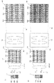
図2(B)に模式的に示すように、液晶パネル14aを構成するサブ画素PEは、カラー表示画素(いわゆる画素)よりも細分化されたものであり、縦横2次元的に一様に配列されており、緑色の第1サブ画素PGと、白色の第2サブ画素PWと、マゼンダ色の第3サブ画素PMとに区分されている。まず、緑色の第1サブ画素PG(G)は、X方向の横一列に隙間なく配列されている。白色の第2サブ画素PW(W)は、緑色の第1サブ画素PGの−Y側に隣接して、X方向の横一列に隙間なく配列されている。マゼンダ色の第3サブ画素PM(Mz)は、白色の第2サブ画素PWの−Y側に隣接して、X方向の横一列に隙間なく配列されている。さらに、緑色の第1サブ画素PG(G)は、マゼンダ色の第3サブ画素PMの−Y側に隣接して、X方向の横一列に隙間なく配列されている。以上のように、本実施形態の場合、横のX方向には同一色のサブ画素PEが並び、縦のY方向には緑色、白色、及びマゼンダ色のサブ画素PEが周期的に並んでいる。ここで、緑色の第1サブ画素PGとマゼンダ色の第3サブ画素PMとについては、それぞれに対応する色のカラーフィルターが各サブ画素PEの開口を覆うように形成されている。白色の第2サブ画素PWについては、これに対応する色のカラーフィルターが設けられていない。ただし、カラーフィルターに代えてセル厚を等しくするような透明膜等を設けることができる。なお、簡単のために説明を省略しているが、各サブ画素PG,PW,PMの境界には、サブ画素PG,PW,PM間の混色を防止するため、ブラックマトリックスを配置してもよい。
As schematically shown in FIG. 2B, the sub-pixels PE constituting the
以上において、緑色の第1サブ画素PGと白色の第2サブ画素PWとマゼンダ色の第3サブ画素PMとの割合は、互いに等しく、1:1:1となっている。つまり、第1及び第2サブ画素PG,PWの合計のサブ画素数と第3サブ画素PMのサブ画素数との比率は2:1となっている。 In the above, the ratios of the green first sub-pixel PG, the white second sub-pixel PW, and the magenta third sub-pixel PM are equal to each other and 1: 1: 1. That is, the ratio of the total number of subpixels of the first and second subpixels PG and PW to the number of subpixels of the third subpixel PM is 2: 1.
図1に戻って、投射レンズ15は、液晶表示装置14によって変調された画像光GLを、不図示のスクリーン上にカラーの拡大像として投射する。
Returning to FIG. 1, the
回路装置20は、ビデオ信号等の外部画像信号が入力される画像処理部81と、画像処理部81の出力に基づいて光学系部分10に設けた液晶表示装置14を駆動する表示駆動部82と、画像処理部81の出力に基づいて光学系部分10に設けた光源11を駆動する光源駆動部83と、これらの回路部分81,82,83等の動作を統括的に制御する主制御部88とを備える。
The
画像処理部81は、入力された外部画像信号を各色の諧調等を含む画像信号に変換する色諧調補正部81aを備える。色諧調補正部81aにより、液晶表示装置14の液晶パネル14aを構成する各サブ画素PEによる光変調動作を適切なものとすることが可能になる。なお、画像処理部81は、外部画像信号に対して歪補正や色補正等の各種画像処理を行うこともできる。
The
表示駆動部82は、画像処理部81から出力された画像信号に基づいて液晶表示装置14を動作させることができ、当該画像信号に対応した画像を液晶表示装置14に形成させることができる。つまり、表示駆動部82は、画像処理部81からの画像信号に基づいて、液晶表示装置14の液晶パネル14aに設けた各サブ画素PE(各色のサブ画素PG,PW,PM)を個別に動作させる。具体的には、表示駆動部82は、液晶パネル14aの各サブ画素PEにおける光透過率を適宜変化させるための駆動信号を液晶パネル14aに出力し、各サブ画素PEにおいて定期的に画素駆動信号の書き換えを行わせる。
The
光源駆動部83は、画像処理部81から出力された点灯信号に基づいて光源11を動作させることができ、当該点灯信号に対応する状態の発光を光源11行わせることができる。つまり、光源駆動部83は、光源11に含まれる発光素子EG,ER,EBを個別に点灯させることができる。本実施形態の場合、第1のタイミングで、光源11のうち緑色の発光素子EGと赤色の発光素子ERとを同時に点灯させ、発光部11aから黄色の第1照明光L1を射出させる。また、第2のタイミングで、光源11のうち緑色の発光素子EGと青色の発光素子EBとを同時に点灯させ、発光部11aからシアン色の第2照明光L2を射出させる。
The light
以上のプロジェクター100において、光学系部分10のうち、光源11、レンズ12、及び液晶表示装置14と、回路装置20とを併せたものは、表示装置200を構成しており、単独で画像を表示できる部分となっている。
In the
図3(A)及び3(B)は、光学系部分10等の基本的な動作を説明する概念図である。
FIGS. 3A and 3B are conceptual diagrams for explaining basic operations of the
図3(A)は、光学系部分10による第1表示状態を示しており、光源11は、第1のタイミングとして、緑色の発光素子EGと赤色の発光素子ERとを同時に点灯させ、発光部11aから黄色の第1照明光L1を射出させる。この結果、液晶表示装置14又は液晶パネル14aは、黄色照明光LYで照明され、投射レンズ15によって投射される画像PPは、緑色の第1サブ画素PGに対応するサブ表示画素Pg1と、白色の第2サブ画素PWに対応するサブ表示画素Py1と、マゼンダ色の第3サブ画素PMに対応するサブ表示画素Pr1とを有する。これらのサブ表示画素Pg1,Py1,Pr1は、液晶パネル14aのサブ画素配列に対応して、横方向にそれぞれ一列に配列されるとともに縦方向に順次繰り返し配置される。ここで、緑色の第1サブ画素PGは、第1照明光L1の黄色照明光LYで照明されるが、カラーフィルターによって赤色が除去されるので、結果的に緑色の表示を行う。つまり、サブ表示画素Pg1は、緑色の表示として観察される。次に、白色の第2サブ画素PWは、第1照明光L1の黄色照明光LYで照明され、カラーフィルターによる減光がないので、黄色の表示を行う。つまり、サブ表示画素Py1は、黄色の表示として観察される。最後に、マゼンダ色の第3サブ画素PMは、第1照明光L1の黄色照明光LYで照明されるが、カラーフィルターによってマゼンダの補色すなわち緑色が除去されるので、結果的に赤色の表示を行う。つまり、サブ表示画素Pr1は、赤色の表示として観察される。
FIG. 3A shows a first display state by the
図3(B)は、光学系部分10による第2表示状態を示しており、光源11は、第2のタイミングとして、緑色の発光素子EGと青色の発光素子EBとを同時に点灯させ、発光部11aからシアン色の第2照明光L2を射出させる。この結果、液晶表示装置14又は液晶パネル14aは、シアン色照明光LCで照明され、投射レンズ15によって投射される画像PPは、緑色の第1サブ画素PGに対応するサブ表示画素Pg2と、白色の第2サブ画素PWに対応するサブ表示画素Pc2と、マゼンダ色の第3サブ画素PMに対応するサブ表示画素Pb2とを有する。これらのサブ表示画素Pg2,Pc2,Pb2は、液晶パネル14aのサブ画素配列に対応して、横方向にそれぞれ一列に配列されるとともに縦方向に順次繰り返し配置される。ここで、緑色の第1サブ画素PGは、第2照明光L2のシアン色照明光LCで照明されるが、カラーフィルターによって青色が除去されるので、結果的に緑色の表示を行う。つまり、サブ表示画素Pg2は、緑色の表示として観察される。次に、白色の第2サブ画素PWは、第2照明光L2のシアン色照明光LCで照明され、カラーフィルターによる減光がないので、シアン色の表示を行う。つまり、サブ表示画素Pc2は、シアン色の表示として観察される。最後に、マゼンダ色の第3サブ画素PMは、第2照明光L2のシアン色照明光LCで照明されるが、カラーフィルターによってマゼンダの補色すなわち緑色が除去されるので、結果的に青色の表示を行う。つまり、サブ表示画素Pb2は、青色の表示として観察される。
FIG. 3B shows a second display state by the
図4を参照して、投射レンズ15によって投射される画像PP中の特定画素(特定カラー表示画素又は特定ブロック画素)PXの表示状態について説明する。図3(A)に対応する第1照明光L1による照明時、すなわち緑色及び赤色の発光素子EG,ERを合わせた黄色照明光LYによる照明時に、特定画素PXは、観察者の眼EYに対してサブ表示画素Pg1,Py1,Pr1を連結した第1の画素(ブロック画素)PX1として観察される。一方、図3(B)に対応する第2照明光L2による照明時、すなわち緑色及び青色の発光素子EG,EBを合わせたシアン色照明光LCによる照明時に、特定画素PXは、観察者の眼EYに対してサブ表示画素Pg2,Pc2,Pb2を連結した第2の画素(ブロック画素)PX2として観察される。つまり、第1照明光L1による黄色照明時(第1表示状態)には、緑、黄、及び赤で構成される3つのサブ表示画素Pg1,Py1,Pr1を一組とした第1の画素PX1として表示が行われ、第2照明光L2によるシアン色照明時(第2表示状態)には、緑、シアン、及び青で構成される3つのサブ表示画素Pg2,Pc2,Pb2を一組とした第2の画素PX2として表示が行われる。そして、第1の画素PX1と第2の画素PX2とは、例えば2フレームの半分の時間で切り替えられるので、両画素PX1,PX2を合わせたものが画像中の特定点のカラー画素(画素ブロック)を表すことになる。つまり、投射すべき画像中の特定点の画像信号は、両画素PX1,PX2に対応する信号を合わせたものに対応する。
With reference to FIG. 4, the display state of the specific pixel (specific color display pixel or specific block pixel) PX in the image PP projected by the
図5に基づいて、液晶表示装置14と光源11との具体的な動作を説明する。まず、緑色の発光素子EGは常時点灯しており、緑色の照明すなわちG照明は連続している。また、赤色の発光素子ERは周期的に点灯しており、2フレームに対応する基本周期T0のうち後半の期間TRにおいて、赤色の照明すなわちR照明が間欠的に行われる。青色の発光素子EBも周期的に点灯しており、基本周期T0のうち前半の期間TBにおいて、青色の照明すなわちB照明が間欠的に行われる。
Specific operations of the liquid
各色のサブ画素PG,PW,PMの書き換えについては、フレームの初期の期間t1において、マゼンダ色の第3サブ画素PMに対して、青色に対応する駆動信号(青色の信号)の書き換えが行われる。この際、赤色の発光素子ERと青色の発光素子EBとは、混色を避けるために停止している。この期間t1の次の期間t2において、緑色の第1サブ画素PGに対して、緑色に対応する駆動信号(緑色の信号)の書き換えが行われる。この際、青色の発光素子EBが点灯しているが、これらのサブ画素は互いに干渉しない。この期間t2の次の期間t3において、白色の第2サブ画素PWに対して、緑色に対応する駆動信号(緑色の信号)の書き換えが行われる。この際、緑色の発光素子EGのほかに青色の発光素子EBが点灯しており、白色の第2サブ画素PWは、黄色照明光LYすなわち第1照明光L1で照明される。この期間t3の次の期間t4において、マゼンダ色の第3サブ画素PMに対して、赤色に対応する駆動信号(赤色の信号)の書き換えが行われる。この際、赤色の発光素子ERと青色の発光素子EBとは、混色を避けるために停止している。この期間t4の次の期間t5において、R照明が開始される。この期間t5の次の期間t6において、白色の第2サブ画素PWに対して、緑色に対応する駆動信号(緑色の信号)の書き換えが行われる。この際、緑色の発光素子EGのほかに赤色の発光素子ERが点灯しており、白色の第2サブ画素PWは、シアン色照明光LCすなわち第2照明光L2で照明される。
Regarding the rewriting of the subpixels PG, PW, and PM of each color, the driving signal (blue signal) corresponding to blue is rewritten to the third subpixel PM of magenta color in the initial period t1 of the frame. . At this time, the red light emitting element ER and the blue light emitting element EB are stopped to avoid color mixing. In a period t2 next to the period t1, the green driving signal (green signal) is rewritten for the first green subpixel PG. At this time, the blue light emitting element EB is lit, but these sub-pixels do not interfere with each other. In the period t3 next to the period t2, the white second subpixel PW is rewritten with the drive signal (green signal) corresponding to green. At this time, in addition to the green light emitting element EG, the blue light emitting element EB is lit, and the white second sub-pixel PW is illuminated with the yellow illumination light LY, that is, the first illumination light L1. In a period t4 subsequent to the period t3, the drive signal (red signal) corresponding to red is rewritten to the magenta third sub-pixel PM. At this time, the red light emitting element ER and the blue light emitting element EB are stopped to avoid color mixing. In the next period t5 after the period t4, the R illumination is started. In a period t6 next to the period t5, the white second subpixel PW is rewritten with a drive signal (green signal) corresponding to green. At this time, the red light emitting element ER is turned on in addition to the green light emitting element EG, and the white second sub-pixel PW is illuminated with the cyan illumination light LC, that is, the second illumination light L2.
以上において、期間t2,t3は、図3(A)の第1表示状態に相当するものとなっている。また、期間t5,t6は、図3(B)の第2表示状態に相当するものとなっている。 In the above, the periods t2 and t3 correspond to the first display state in FIG. The periods t5 and t6 correspond to the second display state in FIG.
図6(A)〜6(D)は、各色のサブ画素PG,PW,PMの書き換えを視覚的に説明する図である。図6(A)は、マゼンダ色の第3サブ画素PMに対する青色信号の書き換え又は書き込みを示しており、図5の期間t1中の処理を説明している。これにより、マゼンダ色の第3サブ画素PMによる青色表示が準備される。図6(B)は、緑色の第1サブ画素PGに対する緑色信号の書き換え又は書き込みを示しており、図5の期間t2中の処理を説明している。これにより、緑色の第1サブ画素PGによる緑色表示が徐々に更新される。図6(C)は、白色の第2サブ画素PWに対する緑色信号の書き換え又は書き込みを示しており、図5の期間t3中の処理を説明している。これにより、白色の第2サブ画素PWによる緑色表示(ここでは黄色表示)が徐々に更新される。図6(D)は、マゼンダ色の第3サブ画素PMに対する赤色信号の書き換え又は書き込みを示しており、図5の期間t4中の処理を説明している。これにより、マゼンダ色の第3サブ画素PMによる赤色表示が準備される。 6A to 6D are diagrams for visually explaining rewriting of the sub-pixels PG, PW, and PM of the respective colors. FIG. 6A shows rewriting or writing of a blue signal to the magenta third sub-pixel PM, and illustrates the processing during the period t1 in FIG. As a result, blue display by the magenta third sub-pixel PM is prepared. FIG. 6B illustrates rewriting or writing of a green signal to the green first sub-pixel PG, and illustrates the processing during the period t2 in FIG. Thereby, the green display by the green first sub-pixel PG is gradually updated. FIG. 6C shows rewriting or writing of the green signal to the white second sub-pixel PW, and the process during the period t3 in FIG. 5 is described. Thereby, the green display (here, yellow display) by the white second sub-pixel PW is gradually updated. FIG. 6D illustrates rewriting or writing of a red signal to the magenta third sub-pixel PM, and illustrates the processing during the period t4 in FIG. As a result, red display by the magenta third sub-pixel PM is prepared.
なお、図6(B)の期間t2では、緑色の発光素子EGを点灯したままで緑色の第1サブ画素PGを書き換えているが、混色の等の問題は生じない。また、図6(C)の期間t3では、青色の発光素子EBを点灯したままで白色の第2サブ画素PWを書き換えているが、混色の等の問題は生じない。なお、図示を省略しているが、期間t6においても、赤色の発光素子ERを点灯したままで緑色信号によって白色の第2サブ画素PWを書き換えているが、混色の等の問題は生じない。以上の第2サブ画素PWについては、期間t2,t3の黄色表示と、期間t5,t6のシアン色表示とを合わせた全体で緑色表示を行っている。 Note that in the period t2 in FIG. 6B, the green first sub-pixel PG is rewritten while the green light-emitting element EG is turned on, but there is no problem of color mixing or the like. Further, in the period t3 in FIG. 6C, the white second sub-pixel PW is rewritten while the blue light-emitting element EB is lit, but there is no problem such as color mixing. Although illustration is omitted, the white second sub-pixel PW is rewritten by the green signal while the red light emitting element ER is lit even in the period t6, but the problem of color mixing does not occur. For the second sub-pixel PW, green display is performed as a whole by combining yellow display in the periods t2 and t3 and cyan display in the periods t5 and t6.
ここで、白色の第2サブ画素PWによる表示についてより詳しく説明する。図3(A)に示す第1表示状態において、白色の第2サブ画素PWによって、スクリーン上で黄色のサブ表示画素Py1が形成される。一方、図3(B)に示す第2表示状態において、白色の第2サブ画素PWによって、スクリーン上でシアン色のサブ表示画素Pc2が形成される。これらは、第1のタイミングのR照明に相当する期間t5,t6(図5参照)と、第2のタイミングのB照明に相当する期間t2,t3(図5参照)とにそれぞれ対応しており、周期的に高速で繰り返されるので、視覚的には、シアン色のサブ表示画素Pc2と黄色のサブ表示画素Py1とが合成されたものとして認識される(図4等参照)。つまり、観察者は、黄色とシアン色とを加算した色、すなわち緑色に白色を加算した色を観察することになる。ここで、白色はその明るさの約80%が緑色成分であり緑に白を加えても緑と感じさせる特性があるので、白の加算によって色調を変えることなく見かけ上の明るさを稼ぐことができる。さらに、緑色の第1サブ画素PGに加えて白色の第2サブ画素PWによって投射画像の解像度を向上させることができ、緑色の第1サブ画素PGのみによる解像度の2倍の解像度とすることができる。ここで、マゼンダ色の第3サブ画素PMによって、赤色のサブ表示画素Pr1と、青色のサブ表示画素Pb2とを形成するので、赤色や青色については形式上解像度が低下するが、見た目の解像度は、緑色の第1サブ画素PGと白色の第2サブ画素PWとによって高く維持される。
Here, the display by the white second sub-pixel PW will be described in more detail. In the first display state shown in FIG. 3A, the yellow sub-display pixel Py1 is formed on the screen by the white second sub-pixel PW. On the other hand, in the second display state shown in FIG. 3B, a cyan sub-display pixel Pc2 is formed on the screen by the white second sub-pixel PW. These correspond to periods t5 and t6 (see FIG. 5) corresponding to the R illumination at the first timing and periods t2 and t3 (see FIG. 5) corresponding to the B illumination at the second timing, respectively. Since it is periodically repeated at high speed, it is visually recognized that the cyan sub-display pixel Pc2 and the yellow sub-display pixel Py1 are synthesized (see FIG. 4 and the like). That is, the observer observes a color obtained by adding yellow and cyan, that is, a color obtained by adding white to green. Here, about 80% of the brightness of white is a green component, and even if white is added to green, there is a characteristic that makes it feel green, so by adding white, you can gain apparent brightness without changing the color tone Can do. Further, the resolution of the projected image can be improved by the white second sub-pixel PW in addition to the green first sub-pixel PG, and the resolution can be double that of the green first sub-pixel PG alone. it can. Here, since the red sub-display pixel Pr1 and the blue sub-display pixel Pb2 are formed by the magenta third sub-pixel PM, the resolution in terms of form is reduced for red and blue, but the apparent resolution is The green first sub-pixel PG and the white second sub-pixel PW are kept high.
以上のように、本実施形態のプロジェクター100によれば、黄色照明光LYによって、第1サブ画素PG及び第2サブ画素PWで緑を表すとともに、第3サブ画素PMで赤を表し、シアン色の照明光によって、第1サブ画素PG及び第2サブ画素PWで緑を表すとともに、第3サブ画素PMで青を表すので、緑色系の第1及び第2サブ画素PG,PWによって見た目の解像度と明るさを確保することができる。なお、マゼンダ色の第3サブ画素PMによって赤色や青色を表すことができる。本実施形態では、赤色や青色についてはフィールドシーケンシャル表示を行っていることになり、緑色ついては連続表示を行っていることになる。このため、カラーブレークアップを目立たないものとすることができる。
As described above, according to the
この発明は、上記の実施形態に限られるものではなく、その要旨を逸脱しない範囲において種々の態様で実施することが可能である。 The present invention is not limited to the above embodiment, and can be implemented in various modes without departing from the scope of the invention.
例えば、白色の第2サブ画素PWについては、緑色のカラーフィルターを追加した緑色のサブ画素とすることができる。この場合も、緑色のサブ画素密度を高めて画像の解像度や明るさを高めることができる。さらに、白色の第2サブ画素PWについては、黄色のカラーフィルターを追加した黄色のサブ画素とすることができる。つまり、第2サブ画素PWは、緑色を含むものであれば、光源の輝度、カラーバランス等に応じて適宜色を設定することができる。 For example, the white second subpixel PW may be a green subpixel to which a green color filter is added. Also in this case, the resolution and brightness of the image can be increased by increasing the green sub-pixel density. Further, the white second sub-pixel PW can be a yellow sub-pixel to which a yellow color filter is added. That is, as long as the second sub-pixel PW includes green, a color can be appropriately set according to the luminance, color balance, and the like of the light source.
また、液晶パネル14aにおけるサブ画素PG,PW,PMの配列や密度は、図2(B)に示すものに限らず、例えばBayer型とすることもできる。この場合、1組の4サブ画素(つまりブロック画素)については、緑、白、及びマゼンダのうちいずれを2つとすることもできる。
Further, the arrangement and density of the sub-pixels PG, PW, and PM in the
上記実施形態では、光源11の発光素子EG,ER,EBをLEDで形成するとしたが、発光素子EG,ER,EBを他の発光素子で形成することもできる。
In the above embodiment, the light emitting elements EG, ER, and EB of the
上記実施形態では、光源11からの照明光ILをそのまま用いているが、照明光ILを特定方向の偏光に揃えることもできる。
In the above embodiment, the illumination light IL from the
液晶パネル14aは、透過型に限らず、反射型とすることができる。ここで、「透過型」とは、液晶パネルが光を透過するタイプであることを意味しており、「反射型」とは、液晶パネルが光を反射するタイプであることを意味している。
The
プロジェクターとしては、投射面を観察する方向から画像投射を行う前面投射型のプロジェクターと、投射面を観察する方向とは反対側から画像投射を行う背面投射型のプロジェクターとがあるが、図1等に示すプロジェクターの構成は、いずれにも適用可能である。 As a projector, there are a front projection type projector that projects an image from the direction of observing the projection surface, and a rear projection type projector that projects an image from the side opposite to the direction of observing the projection surface. Any of the projector configurations shown in FIG.
液晶パネル14aに代えて、カラーフィルターを形成したマイクロミラーをサブ画素とするデジタル・マイクロミラー・デバイス等を、光変調素子として用いることもできる。
Instead of the
10…光学系部分、 11…光源、 11a…発光部、 11b…凹面ミラー、 12…レンズ、 14…液晶表示装置、 14a…液晶パネル、 15…投射レンズ、 20…回路装置、 81…画像処理部、 81a…色諧調補正部、 82…表示駆動部、 83…光源駆動部、 88…主制御部、 100…プロジェクター、 200…表示装置、 EG,ER,EB…発光素子、 GL…画像光、 IL,L1,L2…照明光、 LC…シアン色照明光、 LY…黄色照明光、 OA…光軸、 Pb2,Pc2…サブ表示画素、 PE…サブ画素、 PG…第1サブ画素、 PW…第2サブ画素、 PM…第3サブ画素、 Pg1,Py1,Pr1…サブ表示画素、 Pg2,Pc2,Pb2…サブ表示画素
DESCRIPTION OF
Claims (5)
黄色の照明光と、シアン色の照明光とによって前記光変調素子を照明可能な光源と、を備え、
前記黄色の照明光によって、前記第1サブ画素及び前記第2サブ画素で緑を表すとともに、前記第3サブ画素で赤を表し、
前記シアン色の照明光によって、前記第1サブ画素及び前記2サブ画素で緑を表すとともに、前記第3サブ画素で青を表し、
前記光源は、前記黄色の照明光と、前記シアン色の照明光とを時分割で切り替えつつ前記光変調素子を照明し、
前記黄色の照明光によって、緑色の前記第1サブ画素と、白色の前記第2サブ画素と、マゼンダ色の前記第3サブ画素とを照明する際に、マゼンダ色の前記第3サブ画素を赤色の信号で動作させるとともに、緑色の前記第1サブ画素及び白色の前記第2サブ画素を緑の信号で動作させ、
前記シアン色の照明光によって、緑色の前記第1サブ画素と、白色の前記第2サブ画素と、マゼンダ色の前記第3サブ画素とを照明する際に、マゼンダ色の前記第3サブ画素を青色の信号で動作させるとともに、緑色の前記第1サブ画素及び白色の前記第2サブ画素を緑の信号で動作させる、表示装置。 A light modulation element having a green first sub-pixel, a white second sub-pixel, and a magenta third sub-pixel;
A light source capable of illuminating the light modulation element with yellow illumination light and cyan illumination light,
The yellow illumination light represents green in the first subpixel and the second subpixel, and red in the third subpixel,
By the illumination light of the cyan, together with representative of green in the first sub-pixel and the second sub-pixel, and display the blue in the third sub-pixel,
The light source illuminates the light modulation element while switching the yellow illumination light and the cyan illumination light in a time-sharing manner,
When the yellow illumination light illuminates the first sub-pixel in green, the second sub-pixel in white, and the third sub-pixel in magenta color, the third sub-pixel in magenta color is red And the green first sub-pixel and the white second sub-pixel are operated with a green signal,
When illuminating the first sub-pixel of green, the second sub-pixel of white, and the third sub-pixel of magenta with the cyan illumination light, the third sub-pixel of magenta is A display device that operates with a blue signal and operates the green first sub-pixel and the white second sub-pixel with a green signal .
前記表示装置によって形成された画像を投射する投射レンズと、を備えるプロジェクター。 A display device according to any one of claims 1 to 4 ,
A projector comprising: a projection lens that projects an image formed by the display device.
Priority Applications (3)
| Application Number | Priority Date | Filing Date | Title |
|---|---|---|---|
| JP2011062563A JP5708104B2 (en) | 2011-03-22 | 2011-03-22 | Display device and projector |
| US13/418,686 US8711070B2 (en) | 2011-03-22 | 2012-03-13 | Display device and projector |
| CN201210074810.2A CN102692760B (en) | 2011-03-22 | 2012-03-20 | Display device and projector |
Applications Claiming Priority (1)
| Application Number | Priority Date | Filing Date | Title |
|---|---|---|---|
| JP2011062563A JP5708104B2 (en) | 2011-03-22 | 2011-03-22 | Display device and projector |
Publications (3)
| Publication Number | Publication Date |
|---|---|
| JP2012198400A JP2012198400A (en) | 2012-10-18 |
| JP2012198400A5 JP2012198400A5 (en) | 2014-04-17 |
| JP5708104B2 true JP5708104B2 (en) | 2015-04-30 |
Family
ID=46858328
Family Applications (1)
| Application Number | Title | Priority Date | Filing Date |
|---|---|---|---|
| JP2011062563A Expired - Fee Related JP5708104B2 (en) | 2011-03-22 | 2011-03-22 | Display device and projector |
Country Status (3)
| Country | Link |
|---|---|
| US (1) | US8711070B2 (en) |
| JP (1) | JP5708104B2 (en) |
| CN (1) | CN102692760B (en) |
Families Citing this family (2)
| Publication number | Priority date | Publication date | Assignee | Title |
|---|---|---|---|---|
| WO2014158147A1 (en) | 2013-03-27 | 2014-10-02 | Hewlett-Packard Development Company, L.P. | Scanner |
| TWI603305B (en) * | 2013-09-27 | 2017-10-21 | 鴻海精密工業股份有限公司 | Display device, joint display and display panel |
Family Cites Families (15)
| Publication number | Priority date | Publication date | Assignee | Title |
|---|---|---|---|---|
| JP2000035569A (en) | 1998-07-17 | 2000-02-02 | Hitachi Ltd | Color liquid crystal display panel and projection type liquid crystal display device |
| JP2002341439A (en) | 2001-05-18 | 2002-11-27 | Fujitsu General Ltd | Liquid crystal projector device |
| US6863401B2 (en) * | 2001-06-30 | 2005-03-08 | Texas Instruments Incorporated | Illumination system |
| JP3938537B2 (en) * | 2002-10-17 | 2007-06-27 | シャープ株式会社 | Display device, light-emitting device used therefor, and display method |
| KR20040103997A (en) * | 2003-06-02 | 2004-12-10 | 엘지.필립스 엘시디 주식회사 | Liquid crystal display panel and method and apparatus for driving the same |
| JP4143533B2 (en) * | 2003-12-24 | 2008-09-03 | Necディスプレイソリューションズ株式会社 | Light source device, image display device |
| KR101029432B1 (en) * | 2003-12-29 | 2011-04-14 | 엘지디스플레이 주식회사 | Method and Apparatus of Driving Liquid Crystal Display |
| JP2005352251A (en) * | 2004-06-11 | 2005-12-22 | Olympus Corp | Color image display apparatus |
| JP4773811B2 (en) * | 2005-12-01 | 2011-09-14 | キヤノン株式会社 | Color image display device |
| US7580023B2 (en) * | 2005-12-19 | 2009-08-25 | Philips Lumileds Lighting Co., Llc | Color LCD with bi-color sequential backlight |
| KR101191451B1 (en) * | 2006-06-09 | 2012-10-18 | 엘지디스플레이 주식회사 | LCD and drive method thereof |
| WO2008047725A1 (en) * | 2006-10-13 | 2008-04-24 | Sharp Kabushiki Kaisha | Display device, and signal converting device |
| WO2009040758A2 (en) * | 2007-09-26 | 2009-04-02 | Koninklijke Philips Electronics N.V. | Spectrum-sequential display |
| CN101435935B (en) * | 2007-11-13 | 2010-09-15 | 上海中航光电子有限公司 | Double-field sequence LCD device display method |
| JP4760920B2 (en) * | 2009-01-26 | 2011-08-31 | ソニー株式会社 | Color display device |
-
2011
- 2011-03-22 JP JP2011062563A patent/JP5708104B2/en not_active Expired - Fee Related
-
2012
- 2012-03-13 US US13/418,686 patent/US8711070B2/en active Active
- 2012-03-20 CN CN201210074810.2A patent/CN102692760B/en active Active
Also Published As
| Publication number | Publication date |
|---|---|
| US20120242714A1 (en) | 2012-09-27 |
| JP2012198400A (en) | 2012-10-18 |
| US8711070B2 (en) | 2014-04-29 |
| CN102692760B (en) | 2014-12-24 |
| CN102692760A (en) | 2012-09-26 |
Similar Documents
| Publication | Publication Date | Title |
|---|---|---|
| JP5971976B2 (en) | Liquid crystal display device and control method thereof | |
| US20070236444A1 (en) | Liquid crystal display device and driving method thereof | |
| JP2005321524A (en) | Light source device and projector | |
| US9620044B2 (en) | Image display device and drive method therefor | |
| US9548013B2 (en) | Image display device and drive method therefor | |
| WO2016104340A1 (en) | Display device and method for driving same | |
| US20110221788A1 (en) | Liquid crystal display and picture display system | |
| JP2010113125A (en) | Liquid crystal display device | |
| WO2019064985A1 (en) | Display device | |
| JP2008517327A (en) | High contrast LCD display | |
| JP2017187536A (en) | Light source device and image projection device | |
| JP2006047414A (en) | Color display apparatus | |
| US20090135313A1 (en) | Method for projecting colored video image and system thereof | |
| JP5708104B2 (en) | Display device and projector | |
| JP2008139700A (en) | Image display device | |
| WO2016103922A1 (en) | Colour image display device, and colour image display method | |
| JP5958146B2 (en) | Projector and projector control method | |
| WO2018008720A1 (en) | Display device | |
| JP4429656B2 (en) | Image projection apparatus and image projection method | |
| JP5150183B2 (en) | Projection display device | |
| JP2009162988A (en) | Projector, and image display method in projector | |
| JP2012198400A5 (en) | ||
| JPH0519257A (en) | Color liquid crystal display device | |
| CN113039484A (en) | Image display device | |
| JP2008165126A (en) | Image display device and method, and projector |
Legal Events
| Date | Code | Title | Description |
|---|---|---|---|
| A521 | Request for written amendment filed |
Free format text: JAPANESE INTERMEDIATE CODE: A523 Effective date: 20140305 |
|
| A621 | Written request for application examination |
Free format text: JAPANESE INTERMEDIATE CODE: A621 Effective date: 20140305 |
|
| A977 | Report on retrieval |
Free format text: JAPANESE INTERMEDIATE CODE: A971007 Effective date: 20141106 |
|
| A131 | Notification of reasons for refusal |
Free format text: JAPANESE INTERMEDIATE CODE: A131 Effective date: 20141111 |
|
| A521 | Request for written amendment filed |
Free format text: JAPANESE INTERMEDIATE CODE: A523 Effective date: 20150106 |
|
| RD04 | Notification of resignation of power of attorney |
Free format text: JAPANESE INTERMEDIATE CODE: A7424 Effective date: 20150106 |
|
| TRDD | Decision of grant or rejection written | ||
| A01 | Written decision to grant a patent or to grant a registration (utility model) |
Free format text: JAPANESE INTERMEDIATE CODE: A01 Effective date: 20150203 |
|
| A61 | First payment of annual fees (during grant procedure) |
Free format text: JAPANESE INTERMEDIATE CODE: A61 Effective date: 20150216 |
|
| R150 | Certificate of patent or registration of utility model |
Ref document number: 5708104 Country of ref document: JP Free format text: JAPANESE INTERMEDIATE CODE: R150 |
|
| S531 | Written request for registration of change of domicile |
Free format text: JAPANESE INTERMEDIATE CODE: R313531 |
|
| R350 | Written notification of registration of transfer |
Free format text: JAPANESE INTERMEDIATE CODE: R350 |
|
| LAPS | Cancellation because of no payment of annual fees |