JP5706660B2 - Turbine and turbine blade winglets - Google Patents
Turbine and turbine blade winglets Download PDFInfo
- Publication number
- JP5706660B2 JP5706660B2 JP2010233176A JP2010233176A JP5706660B2 JP 5706660 B2 JP5706660 B2 JP 5706660B2 JP 2010233176 A JP2010233176 A JP 2010233176A JP 2010233176 A JP2010233176 A JP 2010233176A JP 5706660 B2 JP5706660 B2 JP 5706660B2
- Authority
- JP
- Japan
- Prior art keywords
- turbine blade
- winglet
- trailing edge
- tip region
- blade
- Prior art date
- Legal status (The legal status is an assumption and is not a legal conclusion. Google has not performed a legal analysis and makes no representation as to the accuracy of the status listed.)
- Active
Links
- 238000001816 cooling Methods 0.000 claims description 18
- 238000005553 drilling Methods 0.000 description 4
- 238000013459 approach Methods 0.000 description 2
- 230000004075 alteration Effects 0.000 description 1
- 230000015556 catabolic process Effects 0.000 description 1
- 238000006731 degradation reaction Methods 0.000 description 1
- 230000003647 oxidation Effects 0.000 description 1
- 238000007254 oxidation reaction Methods 0.000 description 1
- 238000006467 substitution reaction Methods 0.000 description 1
Images


Classifications
-
- F—MECHANICAL ENGINEERING; LIGHTING; HEATING; WEAPONS; BLASTING
- F01—MACHINES OR ENGINES IN GENERAL; ENGINE PLANTS IN GENERAL; STEAM ENGINES
- F01D—NON-POSITIVE DISPLACEMENT MACHINES OR ENGINES, e.g. STEAM TURBINES
- F01D5/00—Blades; Blade-carrying members; Heating, heat-insulating, cooling or antivibration means on the blades or the members
- F01D5/12—Blades
- F01D5/14—Form or construction
- F01D5/141—Shape, i.e. outer, aerodynamic form
- F01D5/145—Means for influencing boundary layers or secondary circulations
-
- F—MECHANICAL ENGINEERING; LIGHTING; HEATING; WEAPONS; BLASTING
- F01—MACHINES OR ENGINES IN GENERAL; ENGINE PLANTS IN GENERAL; STEAM ENGINES
- F01D—NON-POSITIVE DISPLACEMENT MACHINES OR ENGINES, e.g. STEAM TURBINES
- F01D5/00—Blades; Blade-carrying members; Heating, heat-insulating, cooling or antivibration means on the blades or the members
- F01D5/12—Blades
- F01D5/14—Form or construction
- F01D5/20—Specially-shaped blade tips to seal space between tips and stator
Landscapes
- Engineering & Computer Science (AREA)
- Mechanical Engineering (AREA)
- General Engineering & Computer Science (AREA)
- Physics & Mathematics (AREA)
- Fluid Mechanics (AREA)
- Turbine Rotor Nozzle Sealing (AREA)
Description
本発明は、タービンエンジンに関し、具体的には、タービンブレードに関する。 The present invention relates to a turbine engine, and more particularly to a turbine blade.
タービンブレードは一般的に、タービンエンジン内で回転するシャフトに連結されたロータ上に取付けられる。タービンブレードは、エンジン運転時に該ブレードの機能低下を引起す高温に曝される。 Turbine blades are typically mounted on a rotor that is coupled to a shaft that rotates within a turbine engine. Turbine blades are exposed to high temperatures that cause degradation of the blades during engine operation.
本発明の1つの態様によると、タービンブレードは、前縁、後縁、正圧側面、負圧側面及び先端領域を有する本体と、先端領域内において前縁の下流の箇所から後縁まで延びるように該先端領域内における本体の正圧側面上に配置されたウィングレットとを含む。 According to one aspect of the invention, a turbine blade extends from a body having a leading edge, a trailing edge, a pressure side, a suction side, and a tip region to a trailing edge in the tip region from a location downstream of the leading edge. And a winglet disposed on the pressure side of the main body in the tip region.
本発明の別の態様によると、タービンエンジンは、ロータ組立体と該ロータ組立体上に配置された複数のタービンブレードとを含み、少なくとも1つのブレードは、前縁、後縁、正圧側面、負圧側面及び先端領域を有する本体と、先端領域内において前縁の下流の箇所から後縁まで延びるように該先端領域内における本体の正圧側面上に配置されたウィングレットとを含む。 According to another aspect of the invention, a turbine engine includes a rotor assembly and a plurality of turbine blades disposed on the rotor assembly, the at least one blade comprising a leading edge, a trailing edge, a pressure side, A body having a suction side and a tip region; and a winglet disposed on the pressure side of the body in the tip region so as to extend from a location downstream of the leading edge to a rear edge in the tip region.
これらの及びその他の利点並びに特徴は、図面と関連させて行った以下の説明から一層明らかになるであろう。 These and other advantages and features will become more apparent from the following description taken in conjunction with the drawings.
本発明は、本明細書と共に提出した特許請求の範囲において具体的に指摘しかつ明確に特許請求している。本発明の前述の及びその他の特徴並びに利点は、添付図面と関連させて行った以下の詳細な説明から明らかである。 The invention is specifically pointed out and distinctly claimed in the claims appended hereto. The foregoing and other features and advantages of the present invention will be apparent from the following detailed description taken in conjunction with the accompanying drawings.
詳細な説明は、図面を参照しながら実施例によって、本発明の実施形態をその利点及び特徴と共に説明する。 The detailed description explains embodiments of the invention, together with advantages and features, by way of example with reference to the drawings.
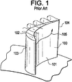
図1は、従来技術のタービンブレード100の実例を示している。運転中に、タービンブレード100が回転すると、空気が、該ブレード100の正圧領域から負圧領域103に流れる。ブレードの先端102付近の空気流れの径路は、矢印105で示している。空気流がブレードの後縁104に近づくにつれて、空気流は、先端102を越えて「漏洩」する。先端102を越えて漏洩する空気流の量は、該空気流が後縁104に近づくにつれて増大する。先端102を越える空気流の漏洩は、タービンブレードの効率を低下させかつ該先端102の温度を上昇させるので望ましくない。先端102領域の温度の上昇は、該先端102領域の材料の酸化及び損耗を引起す。
FIG. 1 shows an example of a prior
図2は、タービンの可動ロータ102の一部分に連結されたタービンブレード200の例示的な実施形態を示している。タービンブレード200は、前縁204、後縁206、遠位ブレード先端領域(先端領域)208、負圧側面210及び正圧側面212を備えた翼形形状の本体を有する。ロータ202上に配置された複数のブレード200は、タービンの流れダクトの内側境界を形成する。流れダクトの外側境界は、シュラウド(図示せず)によって形成される。ブレード200は、ウィングレット214を含む。ウィングレット214は、先端領域208内においてブレード200の正圧側面212上に配置される。ウィングレット214は、前縁204の下流にある先端領域208上の箇所からブレード200の後縁まで延び、かつ後縁214から箇所201に向けてテーパしている。
FIG. 2 illustrates an exemplary embodiment of a
運転中にロータ202は、矢印203で示す方向に回転する。空気は、正圧側面212に沿って前縁204から後縁206に向けてかつ先端領域208に近づくように流れ(矢印205で示す)ようとするが、空気流205はウィングレット214によって妨げられる。ウィングレット214は、後縁206付近において先端領域208を越えて漏洩する空気流205を減少させる。後縁206付近において先端領域208を越えて漏洩する空気流の減少により、ブレード200の効率が増大し、かつ先端領域208内の空気流によって生じる熱伝達が減少する。
During operation, the
図3は、図2の線A−Aに沿ったブレード200の例示的な実施形態の前面断面図を示している。この図示した実施形態は、ブレード200内の空洞302、空洞302と連通状態になった冷却通路304、ブレード200の正圧側面212内に配置されたポート306を含む。空洞は、前縁204、後縁206、先端領域208、負圧側面210及び正圧側面212の壁によって形成される。作動中に、例えば空気又は別のタイプのガスのような加圧ガス301が空洞302を介して冷却通路304に流入しかつポート306から放出されて、ウィングレット214及び先端領域218を冷却する。
FIG. 3 shows a front cross-sectional view of an exemplary embodiment of
図4は、図2の線A−Aに沿ったブレード200の別の例示的な実施形態の前面断面図を示している。この図示した実施形態は、空洞32と連通状態になった冷却通路404、及びウィングレット214の正圧側面端縁部408上に配置されたポート406を含む。冷却通路404は、上記した冷却通路304と同様に作動する。
FIG. 4 shows a front cross-sectional view of another exemplary embodiment of
図5は、図2の線A−Aに沿ったブレード200の別の例示的な実施形態の前面断面図を示している。この図示した実施形態は、空洞32と連通状態になった冷却通路504、及びブレード200の正圧側面212上に配置されたポート506を含む。冷却通路504は、直線501に沿ってウィングレット214及びブレード200の一部分を貫通するように穿孔して通路504及び該ウィングレット214内の通路508を形成することによって製作される。この穿孔は、例えばドリル加工によって行なうことができる。ウィングレット214を貫通する穿孔は、線形穿孔ツールを使用することにより該ウィングレット214に近接してポート506を形成することを可能にする。冷却通路504は、上記した冷却通路304と同様に作動する。幾つかの実施形態では、ウィングレット214内の通路508は、プラグを差込んで該通路508を閉塞することができる。
FIG. 5 illustrates a front cross-sectional view of another exemplary embodiment of
図6は、図2の線A−Aに沿ったブレード200の別の例示的な実施形態の前面断面図を示している。この図示した実施形態は、空洞302及びポート606と連通状態になった冷却通路604を含む。ポート606は、ウィングレット214内に形成されたグルーブ608内に配置される。グルーブ608は、ブレード200の外径からポート606を半径方向内側にオフセットさせる。ポート606のオフセットにより、ブレード200及びロータ202を囲むシュラウドに該ブレード200が接触した場合に、該ポート606が閉塞されるのを回避することができる。冷却通路604は、上記した冷却通路304と同様に作動する。
FIG. 6 shows a front cross-sectional view of another exemplary embodiment of
図7は、タービンエンジン700の一部分の部分断面斜視図を示している。タービンエンジン700は、ウィングレット214を有する複数のブレード200を含み、複数のブレード200はロータ組立体702上に配置されかつシュラウド704によって囲まれる。タービンエンジン700のガス流れ径路の方向は、矢印701で示している。
FIG. 7 shows a partial cross-sectional perspective view of a portion of
限られた数の実施形態に関してのみ本発明を詳細に説明してきたが、本発明がそのような開示した実施形態に限定されるものではないことは、容易に理解される筈である。むしろ、本発明は、これまで説明していないが本発明の技術思想及び技術的範囲に相応するあらゆる数の変形、変更、置換え又は均等な構成を組込むように改良することができる。さらに、本発明の様々な実施形態について説明してきたが、本発明の態様は説明した実施形態の一部のみを含むことができることを理解されたい。従って、本発明は、上記の説明によって限定されるものと見なすべきではなく、本発明は、特許請求の範囲の技術的範囲によってのみ限定される。 Although the present invention has been described in detail only with respect to a limited number of embodiments, it should be readily understood that the invention is not limited to such disclosed embodiments. Rather, the invention can be modified to incorporate any number of variations, alterations, substitutions or equivalent arrangements not heretofore described, but which are commensurate with the spirit and scope of the invention. Moreover, while various embodiments of the invention have been described, it is to be understood that aspects of the invention can include only some of the described embodiments. Accordingly, the invention is not to be seen as limited by the foregoing description, but is limited only by the scope of the claims.
100 タービンブレード
101 正圧領域
102 先端
103 負圧領域
104 後縁
105 矢印
200 タービンブレード
201 箇所
202 ロータ
204 前縁
205 矢印
206 後縁
208 遠位ブレード先端領域(先端領域)
210 負圧側面
212 正圧側面
214 ウィングレット
301 加圧ガス
302 空洞
304 冷却通路
306 ポート
404 冷却通路
406 ポート
408 正圧側面端縁部
504 冷却通路
506 ポート
508 通路
601 シュラウド
604 冷却通路
606 ポート
608 グルーブ
700 タービンエンジン
701 矢印
702 ロータ組立体
704 シュラウド
100
210
Claims (6)
前縁、後縁、正圧側面、負圧側面及び先端領域を有する本体と、
前記先端領域において、前記本体の正圧側面上に配置されたウィングレットと、
を含み、
前記ウィングレットは、前記本体の前記前縁の下流の前記先端領域の箇所から前記本体の前記後縁に位置する前記ウィングレットの反対側の端まで延び、
前記ウィングレットが、前記後縁における幅が前記箇所における幅よりも広くなるように、前記先端領域内において前記後縁から前記箇所に向けてテーパしており、
前記タービンブレードが、内部空洞、前記内部空洞と連通状態になった冷却通路、及び前記本体の前記正圧側面内のポートを含み、
前記ポートが、該タービンブレード上において前記ウィングレットに対して半径方向内側に配置され、
前記タービンブレードが、前記冷却通路と一直線に整列した第2の通路を前記ウィングレット内に含む、
タービンブレード。 A turbine blade,
A body having a leading edge, a trailing edge, a pressure side, a suction side and a tip region;
In the tip region, a winglet disposed on the pressure side of the main body,
Including
The winglet extends from a location of the tip region downstream of the front edge of the body to an opposite end of the winglet located at the rear edge of the body;
The winglet is tapered from the trailing edge toward the location in the tip region such that the width at the trailing edge is wider than the width at the location;
The turbine blade includes an internal cavity, a cooling passage in communication with the internal cavity, and a port in the pressure side of the body;
The port is disposed radially inward relative to the winglet on the turbine blade;
The turbine blade includes a second passage in the winglet that is aligned with the cooling passage;
Turbine blade.
A turbine blade according to any preceding claim, wherein the port is operative to deliver pressurized gas received through the passage and internal cavity.
Applications Claiming Priority (2)
| Application Number | Priority Date | Filing Date | Title |
|---|---|---|---|
| US12/582,927 | 2009-10-21 | ||
| US12/582,927 US8414265B2 (en) | 2009-10-21 | 2009-10-21 | Turbines and turbine blade winglets |
Publications (3)
| Publication Number | Publication Date |
|---|---|
| JP2011089517A JP2011089517A (en) | 2011-05-06 |
| JP2011089517A5 JP2011089517A5 (en) | 2013-11-21 |
| JP5706660B2 true JP5706660B2 (en) | 2015-04-22 |
Family
ID=43877795
Family Applications (1)
| Application Number | Title | Priority Date | Filing Date |
|---|---|---|---|
| JP2010233176A Active JP5706660B2 (en) | 2009-10-21 | 2010-10-18 | Turbine and turbine blade winglets |
Country Status (5)
| Country | Link |
|---|---|
| US (1) | US8414265B2 (en) |
| JP (1) | JP5706660B2 (en) |
| CN (1) | CN102042039B (en) |
| CH (1) | CH702101B1 (en) |
| DE (1) | DE102010038073B4 (en) |
Families Citing this family (33)
| Publication number | Priority date | Publication date | Assignee | Title |
|---|---|---|---|---|
| EP2336492A1 (en) * | 2009-12-16 | 2011-06-22 | Siemens Aktiengesellschaft | Guide vane with a winglet for an energy converting machine and machine for converting energy comprising the guide vane |
| GB201006451D0 (en) * | 2010-04-19 | 2010-06-02 | Rolls Royce Plc | Blades |
| US8777567B2 (en) | 2010-09-22 | 2014-07-15 | Honeywell International Inc. | Turbine blades, turbine assemblies, and methods of manufacturing turbine blades |
| GB201017797D0 (en) * | 2010-10-21 | 2010-12-01 | Rolls Royce Plc | An aerofoil structure |
| US9273561B2 (en) * | 2012-08-03 | 2016-03-01 | General Electric Company | Cooling structures for turbine rotor blade tips |
| US20140044557A1 (en) * | 2012-08-09 | 2014-02-13 | General Electric Company | Turbine blade and method for cooling the turbine blade |
| US9845683B2 (en) | 2013-01-08 | 2017-12-19 | United Technology Corporation | Gas turbine engine rotor blade |
| JP2014148938A (en) * | 2013-02-01 | 2014-08-21 | Siemens Ag | Film-cooled turbine blade for turbomachine |
| US9856739B2 (en) | 2013-09-18 | 2018-01-02 | Honeywell International Inc. | Turbine blades with tip portions having converging cooling holes |
| US9879544B2 (en) | 2013-10-16 | 2018-01-30 | Honeywell International Inc. | Turbine rotor blades with improved tip portion cooling holes |
| US9816389B2 (en) | 2013-10-16 | 2017-11-14 | Honeywell International Inc. | Turbine rotor blades with tip portion parapet wall cavities |
| US9528379B2 (en) | 2013-10-23 | 2016-12-27 | General Electric Company | Turbine bucket having serpentine core |
| US9638041B2 (en) | 2013-10-23 | 2017-05-02 | General Electric Company | Turbine bucket having non-axisymmetric base contour |
| US20150110617A1 (en) * | 2013-10-23 | 2015-04-23 | General Electric Company | Turbine airfoil including tip fillet |
| US9797258B2 (en) | 2013-10-23 | 2017-10-24 | General Electric Company | Turbine bucket including cooling passage with turn |
| US9551226B2 (en) | 2013-10-23 | 2017-01-24 | General Electric Company | Turbine bucket with endwall contour and airfoil profile |
| US9670784B2 (en) | 2013-10-23 | 2017-06-06 | General Electric Company | Turbine bucket base having serpentine cooling passage with leading edge cooling |
| EP2921647A1 (en) | 2014-03-20 | 2015-09-23 | Alstom Technology Ltd | Gas turbine blade comprising bended leading and trailing edges |
| FR3022295B1 (en) * | 2014-06-17 | 2019-07-05 | Safran Aircraft Engines | TURBOMACHINE DAWN COMPRISING AN ANTIWINDER FIN |
| EP2987956A1 (en) | 2014-08-18 | 2016-02-24 | Siemens Aktiengesellschaft | Compressor aerofoil |
| WO2016164533A1 (en) | 2015-04-08 | 2016-10-13 | Horton, Inc. | Fan blade surface features |
| US10253637B2 (en) * | 2015-12-11 | 2019-04-09 | General Electric Company | Method and system for improving turbine blade performance |
| WO2018063353A1 (en) * | 2016-09-30 | 2018-04-05 | Siemens Aktiengesellschaft | Turbine blade and squealer tip |
| US10830082B2 (en) * | 2017-05-10 | 2020-11-10 | General Electric Company | Systems including rotor blade tips and circumferentially grooved shrouds |
| US10830057B2 (en) * | 2017-05-31 | 2020-11-10 | General Electric Company | Airfoil with tip rail cooling |
| US10704406B2 (en) * | 2017-06-13 | 2020-07-07 | General Electric Company | Turbomachine blade cooling structure and related methods |
| CN110945210B (en) * | 2017-08-14 | 2022-05-24 | 西门子能源全球两合公司 | Turbine blade and corresponding maintenance method |
| KR20190127024A (en) * | 2018-05-03 | 2019-11-13 | 두산중공업 주식회사 | Turbine blade and gas turbine including turbine blade |
| FR3081497B1 (en) * | 2018-05-23 | 2020-12-25 | Safran Aircraft Engines | GROSS FOUNDRY BLADE WITH MODIFIED LEAKING EDGE GEOMETRY |
| US10787932B2 (en) | 2018-07-13 | 2020-09-29 | Honeywell International Inc. | Turbine blade with dust tolerant cooling system |
| KR102153066B1 (en) | 2018-10-01 | 2020-09-07 | 두산중공업 주식회사 | Turbine blade having cooling hole at winglet and gas turbine comprising the same |
| US11608746B2 (en) * | 2021-01-13 | 2023-03-21 | General Electric Company | Airfoils for gas turbine engines |
| EP4234885A3 (en) * | 2021-02-04 | 2023-09-06 | Doosan Enerbility Co., Ltd. | Airfoil with a squealer tip cooling system for a turbine blade, corresponding turbine blade, turbine blade assembly, gas turbine and manufacturing method of an airfoil |
Family Cites Families (18)
| Publication number | Priority date | Publication date | Assignee | Title |
|---|---|---|---|---|
| US4768922A (en) | 1986-09-15 | 1988-09-06 | Avco Corporation | Variable stator and shroud assembly |
| US5282721A (en) * | 1991-09-30 | 1994-02-01 | United Technologies Corporation | Passive clearance system for turbine blades |
| US5261789A (en) | 1992-08-25 | 1993-11-16 | General Electric Company | Tip cooled blade |
| DE19913269A1 (en) | 1999-03-24 | 2000-09-28 | Asea Brown Boveri | Turbine blade |
| US6494678B1 (en) | 2001-05-31 | 2002-12-17 | General Electric Company | Film cooled blade tip |
| US6869270B2 (en) | 2002-06-06 | 2005-03-22 | General Electric Company | Turbine blade cover cooling apparatus and method of fabrication |
| GB2409006B (en) | 2003-12-11 | 2006-05-17 | Rolls Royce Plc | Tip sealing for a turbine rotor blade |
| GB2413160B (en) * | 2004-04-17 | 2006-08-09 | Rolls Royce Plc | Turbine rotor blades |
| US7175391B2 (en) * | 2004-07-08 | 2007-02-13 | United Technologies Corporation | Turbine blade |
| US7246999B2 (en) * | 2004-10-06 | 2007-07-24 | General Electric Company | Stepped outlet turbine airfoil |
| US7510376B2 (en) * | 2005-08-25 | 2009-03-31 | General Electric Company | Skewed tip hole turbine blade |
| US7281894B2 (en) * | 2005-09-09 | 2007-10-16 | General Electric Company | Turbine airfoil curved squealer tip with tip shelf |
| US8512003B2 (en) * | 2006-08-21 | 2013-08-20 | General Electric Company | Tip ramp turbine blade |
| US7494319B1 (en) | 2006-08-25 | 2009-02-24 | Florida Turbine Technologies, Inc. | Turbine blade tip configuration |
| EP1953344B1 (en) | 2007-02-05 | 2012-04-11 | Siemens Aktiengesellschaft | Turbine blade |
| GB0724612D0 (en) * | 2007-12-19 | 2008-01-30 | Rolls Royce Plc | Rotor blades |
| EP2093378A1 (en) * | 2008-02-25 | 2009-08-26 | ALSTOM Technology Ltd | Upgrading method for a blade by retrofitting a winglet, and correspondingly upgraded blade |
| GB0813556D0 (en) * | 2008-07-24 | 2008-09-03 | Rolls Royce Plc | A blade for a rotor |
-
2009
- 2009-10-21 US US12/582,927 patent/US8414265B2/en active Active
-
2010
- 2010-10-08 DE DE102010038073.3A patent/DE102010038073B4/en active Active
- 2010-10-18 CH CH01696/10A patent/CH702101B1/en not_active IP Right Cessation
- 2010-10-18 JP JP2010233176A patent/JP5706660B2/en active Active
- 2010-10-21 CN CN201010533223.6A patent/CN102042039B/en active Active
Also Published As
| Publication number | Publication date |
|---|---|
| DE102010038073A1 (en) | 2011-05-19 |
| CN102042039A (en) | 2011-05-04 |
| CH702101A2 (en) | 2011-04-29 |
| DE102010038073B4 (en) | 2023-07-06 |
| JP2011089517A (en) | 2011-05-06 |
| CN102042039B (en) | 2016-01-20 |
| US8414265B2 (en) | 2013-04-09 |
| US20110091327A1 (en) | 2011-04-21 |
| CH702101B1 (en) | 2015-07-15 |
Similar Documents
| Publication | Publication Date | Title |
|---|---|---|
| JP5706660B2 (en) | Turbine and turbine blade winglets | |
| JP6514511B2 (en) | High-wing blade with two partial span shrouds and a curved dovetail | |
| JP5289694B2 (en) | Turbine airfoil curved squealer tip with tip shelf | |
| US8317465B2 (en) | Systems and apparatus relating to turbine engines and seals for turbine engines | |
| JP4876043B2 (en) | Flared tip turbine blade | |
| JP4902157B2 (en) | Turbine blade with a groove at the tip | |
| EP3064713B1 (en) | Turbine rotor blade and corresponding turbine section | |
| JP2011089517A5 (en) | ||
| US9175565B2 (en) | Systems and apparatus relating to seals for turbine engines | |
| US8845280B2 (en) | Blades | |
| JP2006283755A (en) | Fixed turbine blade profile part | |
| JP2011052687A (en) | Molding of platform of non-axisymmetric airfoil | |
| US10036284B2 (en) | Rotating gas turbine blade and gas turbine with such a blade | |
| JP2015524896A5 (en) | ||
| JP2010169089A (en) | Turbine blade or vane with improved cooling efficiency | |
| JP2017141825A (en) | Airfoil for gas turbine engine | |
| CN108868894A (en) | rotor blade and corresponding gas turbine | |
| CN204357493U (en) | For the turbine blade of the turbine section of gas turbine engine | |
| US9765629B2 (en) | Method and cooling system for cooling blades of at least one blade row in a rotary flow machine | |
| EP3704353A1 (en) | Turbine blade with tip trench | |
| JP2017110656A (en) | Interior cooling configurations in turbine rotor blades | |
| EP3301261A1 (en) | Rotor blade | |
| EP3177811B1 (en) | Gas turbine engine compressor | |
| JP2006336651A (en) | Aerofoil having inside fluid passage | |
| EP2620592A1 (en) | Airfoil for a gas turbine engine having a tubular impingement element |
Legal Events
| Date | Code | Title | Description |
|---|---|---|---|
| A521 | Request for written amendment filed |
Free format text: JAPANESE INTERMEDIATE CODE: A523 Effective date: 20131007 |
|
| A621 | Written request for application examination |
Free format text: JAPANESE INTERMEDIATE CODE: A621 Effective date: 20131007 |
|
| A977 | Report on retrieval |
Free format text: JAPANESE INTERMEDIATE CODE: A971007 Effective date: 20140529 |
|
| A131 | Notification of reasons for refusal |
Free format text: JAPANESE INTERMEDIATE CODE: A131 Effective date: 20140603 |
|
| A521 | Request for written amendment filed |
Free format text: JAPANESE INTERMEDIATE CODE: A523 Effective date: 20140828 |
|
| TRDD | Decision of grant or rejection written | ||
| A01 | Written decision to grant a patent or to grant a registration (utility model) |
Free format text: JAPANESE INTERMEDIATE CODE: A01 Effective date: 20150203 |
|
| A61 | First payment of annual fees (during grant procedure) |
Free format text: JAPANESE INTERMEDIATE CODE: A61 Effective date: 20150227 |
|
| R150 | Certificate of patent or registration of utility model |
Ref document number: 5706660 Country of ref document: JP Free format text: JAPANESE INTERMEDIATE CODE: R150 |
|
| R250 | Receipt of annual fees |
Free format text: JAPANESE INTERMEDIATE CODE: R250 |
|
| R250 | Receipt of annual fees |
Free format text: JAPANESE INTERMEDIATE CODE: R250 |
|
| R250 | Receipt of annual fees |
Free format text: JAPANESE INTERMEDIATE CODE: R250 |
|
| R250 | Receipt of annual fees |
Free format text: JAPANESE INTERMEDIATE CODE: R250 |
|
| R250 | Receipt of annual fees |
Free format text: JAPANESE INTERMEDIATE CODE: R250 |
|
| R250 | Receipt of annual fees |
Free format text: JAPANESE INTERMEDIATE CODE: R250 |
|
| S111 | Request for change of ownership or part of ownership |
Free format text: JAPANESE INTERMEDIATE CODE: R313113 |
|
| R350 | Written notification of registration of transfer |
Free format text: JAPANESE INTERMEDIATE CODE: R350 |
|
| R250 | Receipt of annual fees |
Free format text: JAPANESE INTERMEDIATE CODE: R250 |