JP5705646B2 - Split body protective cavity for file cabinet - Google Patents
Split body protective cavity for file cabinet Download PDFInfo
- Publication number
- JP5705646B2 JP5705646B2 JP2011108299A JP2011108299A JP5705646B2 JP 5705646 B2 JP5705646 B2 JP 5705646B2 JP 2011108299 A JP2011108299 A JP 2011108299A JP 2011108299 A JP2011108299 A JP 2011108299A JP 5705646 B2 JP5705646 B2 JP 5705646B2
- Authority
- JP
- Japan
- Prior art keywords
- cavity
- cavity portion
- file
- file cabinet
- engagement
- Prior art date
- Legal status (The legal status is an assumption and is not a legal conclusion. Google has not performed a legal analysis and makes no representation as to the accuracy of the status listed.)
- Expired - Fee Related
Links
Images


Classifications
-
- A—HUMAN NECESSITIES
- A47—FURNITURE; DOMESTIC ARTICLES OR APPLIANCES; COFFEE MILLS; SPICE MILLS; SUCTION CLEANERS IN GENERAL
- A47B—TABLES; DESKS; OFFICE FURNITURE; CABINETS; DRAWERS; GENERAL DETAILS OF FURNITURE
- A47B88/00—Drawers for tables, cabinets or like furniture; Guides for drawers
- A47B88/90—Constructional details of drawers
- A47B88/969—Drawers having means for organising or sorting the content
- A47B88/994—Drawers having means for organising or sorting the content in the form of trays or inserts
Description
本発明は、防火ファイルキャビネットに関し、より具体的には、他の非防火ファイルキャビネット内に、部分的な防火空間を提供するための、分割本体防護キャビティに関する。 The present invention relates to fire-proof file cabinets, and more particularly to split body guard cavities for providing a partial fire-proof space within other non-fire-proof file cabinets.
防火ファイルキャビネットはよく知られている。存在する防火ファイルキャビネットは、典型的には、二重壁の吹込成形された外側ハウジングを有し、これは、スライド式に配置されるファイルキャビネットの引き出しのための、1つまたはそれ以上の開口部を画定する。外側ハウジングは、全体的に、キャビネット内のファイル保管空間の全体を囲み、それゆえ、吹込成形壁の間に形成される断熱空間内に位置決めされる多量の耐火断熱材を必要とする。さらに、ファイルキャビネット引き出しの正面は、耐火断熱材が充填される耐火空間を画定する二重壁を含むように吹込み成形することができ、引き出しが閉じ位置にあるときにファイルキャビネットの正面に耐火性を提供する。現存する防火キャビネットは、キャビネット内の書類を火から保護するには一定期間は効果的であるが、多数の欠点および不足点がある。 Fire file cabinets are well known. Existing fire file cabinets typically have a double wall blow molded outer housing, which has one or more openings for sliding file cabinet drawers. Define the part. The outer housing generally encloses the entire file storage space in the cabinet and therefore requires a large amount of refractory insulation positioned in the insulating space formed between the blow molded walls. In addition, the front of the file cabinet drawer can be blow molded to include a double wall that defines a refractory space filled with refractory insulation, and the fire front of the file cabinet when the drawer is in the closed position. Provide sex. Existing fire protection cabinets are effective for a period of time to protect the documents in the cabinet from fire, but have a number of drawbacks and shortcomings.
現存する耐火ファイルキャビネットの欠点のいくつかは、製造するのが高価であり、重く、移動しにくいということである。これらの欠点は、防火断熱材の実質的な量が外側ハウジングの断熱空間を充填するのに用いられ、全てのファイルキャビネットの引き出しの周りに延びる、という事実に起因する。使用に際して、この全体的に保護された容積は、ファイルキャビネットに保管される実際の品目を保護するのに必要な局所的な容積よりも実質的に大きいことがある。いくつかの例において、全体のファイルキャビネットの単一のファイル引き出しだけに防火が必要となることがある。 Some of the drawbacks of existing refractory file cabinets are that they are expensive to manufacture, are heavy and difficult to move. These disadvantages are due to the fact that a substantial amount of fire insulation is used to fill the insulation space of the outer housing and extends around all file cabinet drawers. In use, this overall protected volume may be substantially greater than the local volume required to protect the actual items stored in the file cabinet. In some instances, fire protection may be required for only a single file drawer in the entire file cabinet.
そこで、廉価に製造できる耐火ファイルキャビネットへの需要がある。また、より少ない耐熱材を使用する耐火ファイルキャビネットへの需要がある。さらに、非耐火ファイルキャビネット内に局所的な耐火空間を提供する、耐火ファイルキャビネットへの需要がある。本発明は、他の需要とともにこれらの需要に応じる。 Therefore, there is a demand for a fireproof file cabinet that can be manufactured at low cost. There is also a need for a fire resistant file cabinet that uses less heat resistant material. In addition, there is a need for a refractory file cabinet that provides a local refractory space within the non-refractory file cabinet. The present invention meets these demands along with other demands.
手短に説明すると、本発明による分割本体防火キャビティは、それぞれファイルキャビネットへ取り付けられるファイル引き出しアセンブリに係合するための、第1および第2の防火キャビティ部を有する。好ましくは、火および水による損傷から保護すべき品目を入れる開放端部保管ボックスは、第2キャビティ部内に配置される。保管ボックスは、引き出しアセンブリが開放位置にあるときに完全にアクセス可能である。これは、第1および第2のキャビティ部の間の係合インターフェースが対角方向に延びることができるからである。ファイル引き出しアセンブリはが閉鎖位置に移動されたとき、第1および第2のキャビティ部は、インターフェースに沿って係合し、ファイルキャビネット内に防火空間および防水空間を画定する。保管ボックスは、そこに保管される内容物を保護するためにそのような空間内に位置決めされる。したがって、本発明は、ファイルキャビネット内に局所的な防火空間を提供し、それにより、ファイルキャビネット内に配置される内容物を保護するために、現存する防火ファイルキャビネットと比較して、ファイルキャビネットの実質的な重量およびコストを減少させる。添付図面は本願の一部をなし、本明細書とともに参照されたい。同様の参照符号は、様々な図において同様の部分を示す。添付図面は以下の通りである。 Briefly, the split body fire cavities according to the present invention have first and second fire cavities for engaging a file drawer assembly each attached to a file cabinet. Preferably, an open end storage box for storing items to be protected from fire and water damage is disposed in the second cavity portion. The storage box is fully accessible when the drawer assembly is in the open position. This is because the engagement interface between the first and second cavity portions can extend diagonally. When the file drawer assembly is moved to the closed position, the first and second cavities engage along the interface and define a fire and waterproof space within the file cabinet. A storage box is positioned in such a space to protect the contents stored therein. Thus, the present invention provides a local fire protection space within the file cabinet, thereby protecting the contents placed within the file cabinet as compared to existing fire protection file cabinets. Reduce substantial weight and cost. The accompanying drawings form part of the present application and should be referred to together with this specification. Like reference symbols indicate like parts in the various drawings. The attached drawings are as follows.
本明細書で示される例示は、本発明の一つの実施形態を一つの形態で示し、そのような例示は、いかなる意味でも本発明の範囲を限定するものであると解釈されるべきではない。 The illustrations presented herein illustrate one embodiment of the invention in one form, and such illustration should not be construed as limiting the scope of the invention in any way.
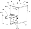
引き出しを詳細に参照し、図1−3を参照すると、参照符号10は、本発明において使用することができる例示的なファイルキャビネットの全体を指す。ファイルキャビネット10は、対向する側壁12のペア、後壁14、頂部壁16、および底部支持ベースを含む外側ハウジング11を備えることができる。外側ハウジング11は、たとえば、木材、プラスチック、またはアルミニウムのような金属から形成することができる。側壁12、頂壁16、および底部支持ベース18は、開口部20を画定することができ、少なくとも1つの第1および第2引き出しアセンブリ22a、22bを開放位置と閉鎖位置との間でスライド式に移動できるように構成される。
Referring to the drawer in detail and referring to FIGS. 1-3,
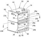
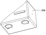
本発明によれば、第1および第2の引き出しアセンブリ22a、22bの少なくとも1つは、ファイルキャビネット10内に保管される品目の局所的な保護を提供するために、分割本体耐火キャビティ24a、24bを備える。各分割本体耐火キャビティ24a、24bは、第1および第2のキャビティ部26a、26bを有し、これらは、それぞれの引き出しアセンブリ22a、22bが閉鎖位置にあるときに、ファイルキャビネット10内に保管された内容物を火から保護するように互いに結合されるように構成される。図8にもっともよく示されるように、第1キャビティ部26aおよび第2キャビティ部26bの各々は、防護空間32を画定する外側壁28および内側壁30を形成するように吹込み成形することができる。防護空間32内は、熱的に絶縁される耐火材料33があり、たとえば、約40%から60%の間の水分、およびナイロンファイバーを含む水和ポルトランドセメントである。第1および第2のキャビティ部26a、26bは、実質的に等しいサイズの引き出しとして示されているが、第1および第2のキャビティ部26a、26bは、等しくないサイズにすることもでき、また、それでも本明細書で説明される利益を提供することができることを理解されたい。
In accordance with the present invention, at least one of the first and
図2、3にもっともよく示されるように、第1キャビティ部26aは、スライド可能とすることができ、または、取り付けブラケット34のペアを用いてファイルキャビネット10の側壁12に固定的に取り付けることもできる。第2キャビティ部26bは、引き出しアセンブリ22a、22bの1つに取り付けられ、それぞれおの引き出しアセンブリに沿ってファイルキャビネット10にスライド可能に取り付けられるように構成される。特に、トラック36のペアは、第2キャビティ部26bの両側部に取り付けられる。トラック36は、ファイルキャビネット10の側壁12に取り付けられた対応するチャネル38のペア内にスライド式に受け入れられるように構成される。トラック36とチャネル38との間の相互作用により、引き出しアセンブリ22a、22bが開放位置と閉鎖位置との間で移動できるようになる。本明細書で説明されるトラック36およびチャネル38は、慣習的なものであり、当業界で他の知られた他の引き出しトラック構成に変更することができることを理解されたい。さらに、引き出しカバー40が第2キャビティ部26bの正面部に固定され、引き出しアセンブリ22a、22bを使用者が開閉するのを支援するためのハンドル42を提供する。また、ファイルキャビネット10への認可されていないアクセスを防止するために、ロックアセンブリ44を引き出しアセンブリ22a、22bに取り付けることができる。
As best shown in FIGS. 2 and 3, the
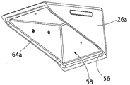
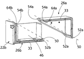
さらに、開放端部保管ボックス46は、第2キャビティ部26b内に位置決めすることができ、紙、ファイル、または他の品目をその中に保管することができる。保管ボックス46は、シート金属、プラスチック、または保管する能力のある他の適当な材料から形成することができる。第2キャビティ部26bは、部分的に保管ボックス46を囲むように構成され、保管ボックス46の内側は、引き出しアセンブリ22a、22bが開放位置にあるときにアクセス可能になる。しかし、引き出しアセンブリ22a、22bが閉鎖位置に移動されたとき、図2、8に最もよく示されるように、第1および第2のキャビティ部26a、26bは、係合インターフェースに沿って互いに結合し、開放端部保管ボックス46およびその中に配置される内容物の全体を囲み、局所的な隔離された防火キャビティを形成する。係合インターフェース48は、概ね第1および第2のキャビティ部26a、26bの下方内側角部52a、52bから上方外側角部54a、5bまで延びる対角平面50(図9)上に提供することができので、保管ボックス46は、それぞれの引き出しアセンブリ22a、22bが開放位置に移動したときに完全にアクセス可能である。係合インターフェース48は、対角係合表面として図示および説明されるが、他の非対角係合表面も本発明の範囲内にあることを理解されたい。
In addition, the open
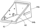
図4−9に最もよく示されるように、各第1キャビティ部26aは、係合開口部58を囲む凹部56を含むことができ、また同様に、各第2キャビティ部26bは、係合開口部62を囲む係合リッジ60を含むことができる。ガスケットのような防水シール64a、64bは、凹部56およびリッジ60の少なくとも一方に取り付けることができ、開口部58、62を囲み、係合インターフェース48(図2)に配置される。たとえば、防水シール64a、64bは、エチレンプロピレンジエンモノマー(EPDM)またはネオプレンなどの弾性重合化製品のようなエラストマから形成することができる。他のタイプの防水シール64a、64bを、第1および第2のキャビティ部26a、26bの間で、係合インターフェース48に沿って使用することができる。
As best shown in FIGS. 4-9, each
少なくとも1つのファイル引き出しアセンブリ内に、分割本体防火キャビティを含むファイルキャビネットを提供することで、多数の利点が実現される。たとえば、ファイル引き出しアセンブリの内容物を保護するのに必要な耐熱絶縁材料の量は、従来技術におけるものよりも実質的に少ない。これは、ファイルキャビネットのハウジング全体を保護する必要が除かれるからである。分割本体防火キャビティは、ファイル引き出しアセンブルの防火のための選択的な使用を可能にし、たとえば、ファイルキャビネット内の他の引き出しアセンブリは防火性でなく、それにより、ファイルキャビネットの製造に必要な断熱材料の量を減らす。本発明は、従来技術よりも防火断熱材の使用量が少ないので製造が廉価であるだけではなく、非耐火ファイルキャビネット内に、局所的な耐火空間を提供することもできる。 A number of advantages are realized by providing a file cabinet including a split body fire cavities within at least one file drawer assembly. For example, the amount of heat resistant insulating material required to protect the contents of the file drawer assembly is substantially less than in the prior art. This is because the need to protect the entire file cabinet housing is eliminated. Split body fire cavities allow selective use for fire protection of file drawer assemblies, for example, other drawer assemblies in the file cabinet are not fire retardant, thereby providing the necessary insulation material for file cabinet manufacturing Reduce the amount of. The present invention is not only less expensive to manufacture because it uses less fire insulation than the prior art, but it can also provide a local fireproof space within a non-fireproof file cabinet.
特定の好ましいバージョンを参照しながら本発明を詳細に説明したが、他のバージョンも可能である。それゆえ、添付の特許請求の範囲の趣旨および範囲は、本明細書の好ましいバージョンの説明に限定されるべきではない。 Although the invention has been described in detail with reference to certain preferred versions, other versions are possible. Therefore, the spirit and scope of the appended claims should not be limited to the description of the preferred version of this specification.
特許請求の範囲、要約、図面を含む明細書等で説明されたあらゆる特徴、開示された方法またはプロセス中のあらゆるステップは、特徴および/またはステップが互いに排他的なものでない限り、任意の組み合わせにおいて組み合わせることができる。特許請求の範囲、要約、図面を含む明細書等で説明された各特徴は、明示的に否定されていない限り、同一、同等または、類似の目的として機能する代替特徴により交換することができる。したがって、明示的に否定していない限り、開示された各特徴は、同等または類似の特徴の属性の単なる一例である。 Any features described in the claims, abstracts, specification including drawings, etc., every step in the disclosed method or process may be combined in any combination, unless the features and / or steps are mutually exclusive. Can be combined. Each feature described in the claims, abstracts, specification including drawings, etc. may be replaced by an alternative feature that serves the same, equivalent, or similar purpose unless expressly denied. Thus, unless expressly denied, each feature disclosed is one example only of an attribute of an equivalent or similar feature.
Claims (15)
前記分割本体防火キャビティは、前記ファイルキャビネットの前記外側ハウジングに取り付けられるように構成される第1キャビティ部を有し、前記第1キャビティ部は、全体として三角形状の対向する側壁を含み、前記第1キャビティ部はさらに、下方内側角部および上方外側角部を含み、
前記分割本体防火キャビティは、前記ファイル引き出しアセンブリに取り付けられるように構成される第2キャビティ部を有し、前記第2キャビティ部は、全体として三角形状の対向する側壁を含み、前記第2キャビティ部はさらに、下方内側角部および上方外側角部を含み、
前記分割本体防火キャビティは、前記第1キャビティ部と前記第2キャビティ部との間の係合インターフェースを有し、前記係合インターフェースは、対角平面上に配置され、前記対角平面は、前記第1キャビティ部および前記第2キャビティ部の前記下方内側角部から、前記第1キャビティ部および前記第2キャビティ部の前記上方外側角部まで延び、前記第1キャビティ部および前記第2キャビティ部は、前記係合インターフェースにおいて互いに結合して、少なくとも1つの前記ファイル引き出しアセンブリが閉鎖位置にあるときに局所的な防火空間を画定するように構成され、
さらに、前記第2キャビティ部内に配置される開放端部保管ボックスを有し、前記第2キャビティ部は、前記開放端部保管ボックスの一部を囲むように構成され、前記第1キャビティ部および前記第2キャビティ部は、少なくとも1つの前記ファイル引き出しアセンブリが閉鎖位置にあるときに、前記開放端部保管ボックスの全体を囲むように、前記係合インターフェースにおいて互いに結合するように構成される、局所的な分割本体防火キャビティ。 A local split body fire cavity for a file cabinet, the file cabinet including an outer housing defining an opening for slidably receiving at least one file drawer assembly;
The split body fire cavities have a first cavity portion configured to be attached to the outer housing of the file cabinet, the first cavity portion including opposing triangular sidewalls as a whole, The one cavity portion further includes a lower inner corner portion and an upper outer corner portion,
The split body fire cavities have a second cavity portion configured to be attached to the file drawer assembly, the second cavity portion including opposing triangular sidewalls as a whole, the second cavity portion Further includes a lower inner corner and an upper outer corner,
The split main body fire prevention cavity has an engagement interface between the first cavity portion and the second cavity portion, and the engagement interface is disposed on a diagonal plane, and the diagonal plane is The first cavity part and the second cavity part extend from the lower inner corner part to the upper outer corner part of the first cavity part and the second cavity part, and the first cavity part and the second cavity part are Coupled to each other at the engagement interface and configured to define a local fire protection space when at least one of the file drawer assemblies is in a closed position;
Furthermore, it has an open end storage box disposed in the second cavity portion, and the second cavity portion is configured to surround a part of the open end storage box, and the first cavity portion and the A second cavity portion is configured to couple to each other at the engagement interface so as to surround the entirety of the open end storage box when at least one of the file drawer assemblies is in a closed position. Split body fire cavities.
前記分割本体防火キャビティは、前記ファイルキャビネットの前記外側ハウジングに取り付けられるように構成される第1キャビティ部を有し、前記第1キャビティ部は、全体として三角形状の対向する側壁を含み、前記第1キャビティ部はさらに、下方内側角部および上方外側角部を含み、
前記分割本体防火キャビティは、前記ファイル引き出しアセンブリに取り付けられるように構成される第2キャビティ部を有し、前記第2キャビティ部は、全体として三角形状の対向する側壁を含み、前記第2キャビティ部はさらに、下方内側角部および上方外側角部を含み、
前記分割本体防火キャビティは、前記第1キャビティ部と前記第2キャビティ部との間の係合インターフェースを有し、前記係合インターフェースは、対角平面上に配置され、前記対角平面は、前記第1キャビティ部および前記第2キャビティ部の前記下方内側角部から、前記第1キャビティ部および前記第2キャビティ部の前記上方外側角部まで延び、前記第1キャビティ部および前記第2キャビティ部は、前記係合インターフェースにおいて互いに結合して、少なくとも1つの前記ファイル引き出しアセンブリが閉鎖位置にあるときに局所的な防火空間を画定するように構成され、
前記第1キャビティ部および前記第2キャビティ部の一方は係合凹部を含み、前記第1キャビティ部および前記第2キャビティ部の他方は係合リッジを備え、前記係合リッジは、前記係合インターフェースに沿って前記係合凹部内に位置決めされる、局所的な分割本体防火キャビティ。 A local split body fire cavity for a file cabinet, the file cabinet including an outer housing defining an opening for slidably receiving at least one file drawer assembly;
The split body fire cavities have a first cavity portion configured to be attached to the outer housing of the file cabinet, the first cavity portion including opposing triangular sidewalls as a whole, The one cavity portion further includes a lower inner corner portion and an upper outer corner portion,
The split body fire cavities have a second cavity portion configured to be attached to the file drawer assembly, the second cavity portion including opposing triangular sidewalls as a whole, the second cavity portion Further includes a lower inner corner and an upper outer corner,
The split main body fire prevention cavity has an engagement interface between the first cavity portion and the second cavity portion, and the engagement interface is disposed on a diagonal plane, and the diagonal plane is The first cavity part and the second cavity part extend from the lower inner corner part to the upper outer corner part of the first cavity part and the second cavity part, and the first cavity part and the second cavity part are Coupled to each other at the engagement interface and configured to define a local fire protection space when at least one of the file drawer assemblies is in a closed position;
One of the first cavity part and the second cavity part includes an engagement recess, and the other of the first cavity part and the second cavity part includes an engagement ridge, and the engagement ridge is the engagement interface. Locally split body fire cavities positioned along the engagement recesses in the engagement recesses.
前記分割本体防火キャビティは、前記ファイルキャビネットの前記外側ハウジングに取り付けられるように構成される第1キャビティ部を有し、前記第1キャビティ部は、全体として三角形状の対向する側壁を含み、前記第1キャビティ部はさらに、下方内側角部および上方外側角部を含み、
前記分割本体防火キャビティは、前記ファイル引き出しアセンブリに取り付けられるように構成される第2キャビティ部を有し、前記第2キャビティ部は、全体として三角形状の対向する側壁を含み、前記第2キャビティ部はさらに、下方内側角部および上方外側角部を含み、
前記分割本体防火キャビティは、前記第1キャビティ部と前記第2キャビティ部との間の係合インターフェースを有し、前記係合インターフェースは、対角平面上に配置され、前記対角平面は、前記第1キャビティ部および前記第2キャビティ部の前記下方内側角部から、前記第1キャビティ部および前記第2キャビティ部の前記上方外側角部まで延び、前記第1キャビティ部および前記第2キャビティ部は、前記係合インターフェースにおいて互いに結合して、少なくとも1つの前記ファイル引き出しアセンブリが閉鎖位置にあるときに局所的な防火空間を画定するように構成され、
前記第1キャビティ部は、前記ファイルキャビネットの前記外側ハウジングに固定的に取り付けられるように構成される、局所的な分割本体防火キャビティ。 A local split body fire cavity for a file cabinet, the file cabinet including an outer housing defining an opening for slidably receiving at least one file drawer assembly;
The split body fire cavities have a first cavity portion configured to be attached to the outer housing of the file cabinet, the first cavity portion including opposing triangular sidewalls as a whole, The one cavity portion further includes a lower inner corner portion and an upper outer corner portion,
The split body fire cavities have a second cavity portion configured to be attached to the file drawer assembly, the second cavity portion including opposing triangular sidewalls as a whole, the second cavity portion Further includes a lower inner corner and an upper outer corner,
The split main body fire prevention cavity has an engagement interface between the first cavity portion and the second cavity portion, and the engagement interface is disposed on a diagonal plane, and the diagonal plane is The first cavity part and the second cavity part extend from the lower inner corner part to the upper outer corner part of the first cavity part and the second cavity part, and the first cavity part and the second cavity part are Coupled to each other at the engagement interface and configured to define a local fire protection space when at least one of the file drawer assemblies is in a closed position;
The first cavity portion is a local split body fire cavities configured to be fixedly attached to the outer housing of the file cabinet.
開口部を画定する外側ハウジングと、
前記外側ハウジングの前記開口部内にスライド式に配置される少なくとも1つのファイル引き出しアセンブリと、を有し、前記少なくとも1つのファイル引き出しアセンブリは、開放端部保管ボックスを有し、
前記ファイルキャビネットはさらに、第1キャビティ部および第2キャビティ部を含む分割本体防火キャビティを有し、前記第1キャビティ部は、前記外側ハウジングに取り付けられ、前記第1キャビティ部は、全体として三角形状の対向する側壁を含み、前記第1キャビティ部はさらに、下方内側角部および上方外側角部を含み、前記第2キャビティ部は、前記ファイル引き出しアセンブリに取り付けられ、且つ、前記開放端部保管ボックスの一部を囲むように構成され、前記第2キャビティ部は、全体として三角形状の対向する側壁を含み、前記第2キャビティ部はさらに、下方内側角部および上方外側角部を含み、前記第1キャビティ部と前記第2キャビティ部との間に係合インターフェースが設けられ、前記係合インターフェースは、対角平面上に配置され、前記対角平面は、前記第1キャビティ部および前記第2キャビティ部の前記下方内側角部から、前記第1キャビティ部および前記第2キャビティ部の前記上方外側角部まで延び、前記開放端部保管ボックスは、前記少なくとも1つのファイル引き出しアセンブリが開放位置にあるときにアクセス可能であり、前記第1キャビティ部および前記第2キャビティ部は、前記少なくとも1つのファイル引き出しアセンブリが閉鎖位置にあるときに、前記開放端部保管ボックスの全体を囲むように前記係合インターフェースで互いに結合するように構成される、ファイルキャビネット。 A file cabinet,
An outer housing defining an opening;
At least one file drawer assembly slidably disposed within the opening of the outer housing, the at least one file drawer assembly having an open end storage box;
The file cabinet further includes a divided main body fire prevention cavity including a first cavity part and a second cavity part, the first cavity part being attached to the outer housing, and the first cavity part having a triangular shape as a whole. The first cavity portion further includes a lower inner corner and an upper outer corner, the second cavity portion is attached to the file drawer assembly, and the open end storage box The second cavity part includes a generally triangular opposing side wall, the second cavity part further including a lower inner corner and an upper outer corner, An engagement interface is provided between the first cavity portion and the second cavity portion, and the engagement interface is The diagonal plane is disposed on a diagonal plane, and the diagonal plane extends from the lower inner corner portion of the first cavity portion and the second cavity portion to the upper outer corner portion of the first cavity portion and the second cavity portion. And the open end storage box is accessible when the at least one file drawer assembly is in an open position, the first cavity portion and the second cavity portion being the at least one file drawer assembly A file cabinet configured to be coupled to each other at the engagement interface so as to surround the entire open end storage box when in a closed position.
前記分割本体防火キャビティは、前記ファイルキャビネットの前記外側ハウジングに取り付けられるように構成される第1キャビティ部を有し、前記第1キャビティ部は、頂部壁、後壁、および対向する側壁を含み、前記頂部壁および前記後壁は、前記第1キャビティ部の前記対向する側壁に接続され、前記対向する側壁は全体として三角形状であり、
前記分割本体防火キャビティは、前記ファイル引き出しアセンブリに取り付けられるように構成される第2キャビティ部を有し、前記第2キャビティ部は、底面壁、正面壁、および対向する側壁を含み、前記底面壁および前記正面壁は、前記第2キャビティ部の前記対向する側壁に接続され、前記第2キャビティ部の前記対向する側壁は、全体として三角形状であり、
前記分割本体防火キャビティは、前記第1キャビティ部と前記第2キャビティ部との間の係合インターフェースを有し、前記第1キャビティ部および前記第2キャビティ部は、前記係合インターフェースにおいて互いに結合して、少なくとも1つの前記ファイル引き出しアセンブリが閉鎖位置にあるときに局所的な防火空間を画定するように構成され、
さらに、前記第2キャビティ部内に配置される開放端部保管ボックスを有し、前記第2キャビティ部は、前記開放端部保管ボックスの一部を囲むように構成され、前記第1キャビティ部および前記第2キャビティ部は、少なくとも1つの前記ファイル引き出しアセンブリが閉鎖位置にあるときに、前記開放端部保管ボックスの全体を囲むように、前記係合インターフェースにおいて互いに結合するように構成される、局所的な分割本体防火キャビティ。 A local split body fire cavity for a file cabinet, the file cabinet including an outer housing defining an opening for slidably receiving at least one file drawer assembly;
The split body fire cavities have a first cavity portion configured to be attached to the outer housing of the file cabinet, the first cavity portion including a top wall, a rear wall, and opposing side walls; The top wall and the rear wall are connected to the opposing side walls of the first cavity portion, and the opposing side walls are generally triangular.
The split body fire cavities have a second cavity portion configured to be attached to the file drawer assembly, the second cavity portion including a bottom wall, a front wall, and opposing sidewalls, the bottom wall And the front wall is connected to the opposing side wall of the second cavity part, and the opposing side wall of the second cavity part is generally triangular.
The split main body fire prevention cavity has an engagement interface between the first cavity part and the second cavity part, and the first cavity part and the second cavity part are coupled to each other at the engagement interface. Configured to define a local fire protection space when the at least one file drawer assembly is in a closed position ;
Furthermore, it has an open end storage box disposed in the second cavity portion, and the second cavity portion is configured to surround a part of the open end storage box, and the first cavity portion and the A second cavity portion is configured to couple to each other at the engagement interface so as to surround the entirety of the open end storage box when at least one of the file drawer assemblies is in a closed position. Split body fire cavities.
前記分割本体防火キャビティは、前記ファイルキャビネットの前記外側ハウジングに取り付けられるように構成される第1キャビティ部を有し、前記第1キャビティ部は、頂部壁、後壁、および対向する側壁を含み、前記頂部壁および前記後壁は、前記第1キャビティ部の前記対向する側壁に接続され、前記対向する側壁は全体として三角形状であり、
前記分割本体防火キャビティは、前記ファイル引き出しアセンブリに取り付けられるように構成される第2キャビティ部を有し、前記第2キャビティ部は、底面壁、正面壁、および対向する側壁を含み、前記底面壁および前記正面壁は、前記第2キャビティ部の前記対向する側壁に接続され、前記第2キャビティ部の前記対向する側壁は、全体として三角形状であり、
前記分割本体防火キャビティは、前記第1キャビティ部と前記第2キャビティ部との間の係合インターフェースを有し、前記第1キャビティ部および前記第2キャビティ部は、前記係合インターフェースにおいて互いに結合して、少なくとも1つの前記ファイル引き出しアセンブリが閉鎖位置にあるときに局所的な防火空間を画定するように構成され、
前記第1キャビティ部および前記第2キャビティ部の一方は係合凹部を含み、前記第1キャビティ部および前記第2キャビティ部の他方は係合リッジを備え、前記係合リッジは、前記係合インターフェースに沿って前記係合凹部内に位置決めされる、局所的な分割本体防火キャビティ。 A local split body fire cavity for a file cabinet, the file cabinet including an outer housing defining an opening for slidably receiving at least one file drawer assembly;
The split body fire cavities have a first cavity portion configured to be attached to the outer housing of the file cabinet, the first cavity portion including a top wall, a rear wall, and opposing side walls; The top wall and the rear wall are connected to the opposing side walls of the first cavity portion, and the opposing side walls are generally triangular.
The split body fire cavities have a second cavity portion configured to be attached to the file drawer assembly, the second cavity portion including a bottom wall, a front wall, and opposing sidewalls, the bottom wall And the front wall is connected to the opposing side wall of the second cavity part, and the opposing side wall of the second cavity part is generally triangular.
The split main body fire prevention cavity has an engagement interface between the first cavity part and the second cavity part, and the first cavity part and the second cavity part are coupled to each other at the engagement interface. Configured to define a local fire protection space when the at least one file drawer assembly is in a closed position ;
One of the first cavity part and the second cavity part includes an engagement recess, and the other of the first cavity part and the second cavity part includes an engagement ridge, and the engagement ridge is the engagement interface. Locally split body fire cavities positioned along the engagement recesses in the engagement recesses.
Applications Claiming Priority (2)
| Application Number | Priority Date | Filing Date | Title |
|---|---|---|---|
| US12/862,193 US8454104B2 (en) | 2010-08-24 | 2010-08-24 | Split-bodied insulated cavity for a file cabinet |
| US12/862,193 | 2010-08-24 |
Publications (3)
| Publication Number | Publication Date |
|---|---|
| JP2012045371A JP2012045371A (en) | 2012-03-08 |
| JP2012045371A5 JP2012045371A5 (en) | 2013-07-25 |
| JP5705646B2 true JP5705646B2 (en) | 2015-04-22 |
Family
ID=44508626
Family Applications (1)
| Application Number | Title | Priority Date | Filing Date |
|---|---|---|---|
| JP2011108299A Expired - Fee Related JP5705646B2 (en) | 2010-08-24 | 2011-05-13 | Split body protective cavity for file cabinet |
Country Status (6)
| Country | Link |
|---|---|
| US (1) | US8454104B2 (en) |
| EP (1) | EP2422649B1 (en) |
| JP (1) | JP5705646B2 (en) |
| CN (1) | CN102370349B (en) |
| CA (1) | CA2745488A1 (en) |
| MX (1) | MX2011005606A (en) |
Families Citing this family (3)
| Publication number | Priority date | Publication date | Assignee | Title |
|---|---|---|---|---|
| US10094160B2 (en) | 2015-03-21 | 2018-10-09 | Michael B. DeBaldo | Tongue and groove modular fire safe |
| US10085554B2 (en) * | 2016-03-15 | 2018-10-02 | Robert A. Schooley, JR. | Gun cabinet |
| CN112353129B (en) * | 2020-11-09 | 2022-03-15 | 佳木斯大学 | Intelligent filing cabinet is deposited with archives to mathematical education |
Family Cites Families (22)
| Publication number | Priority date | Publication date | Assignee | Title |
|---|---|---|---|---|
| US1902795A (en) | 1930-08-30 | 1933-03-21 | Remington Rand Inc | Drawer suspension |
| GB489522A (en) | 1936-05-01 | 1938-07-28 | Remington Rand Inc | Improvements relating to articles of furniture provided with one or more drawers |
| US2333511A (en) * | 1941-10-02 | 1943-11-02 | Diebold Safe & Lock Company | Insulated filing cabinet manufacture and the like |
| US3095838A (en) * | 1960-09-30 | 1963-07-02 | Diebold Inc | Forced entry resistant security file construction |
| US3408966A (en) * | 1966-08-17 | 1968-11-05 | Desoto Inc | Fireproof container |
| JPS4832382Y1 (en) * | 1967-08-16 | 1973-10-03 | ||
| US3705754A (en) * | 1970-02-16 | 1972-12-12 | Hon Ind Inc | Filing units |
| US3817589A (en) * | 1972-11-06 | 1974-06-18 | Shaw Walker Co | Lateral fire resistant file cabinet |
| US3826552A (en) * | 1973-01-29 | 1974-07-30 | Shaw Walker Co | Insulated tape file |
| US3855741A (en) * | 1973-04-12 | 1974-12-24 | Gen Electric | Closure for fire resistant structure |
| US3888557A (en) * | 1974-02-28 | 1975-06-10 | Shaw Walker Co | Insulated inner container for a fire resistant file cabinet |
| US4303286A (en) * | 1980-01-28 | 1981-12-01 | Meilink Industries, Inc. | Insulated filing cabinet |
| CH646541A5 (en) * | 1980-03-18 | 1984-11-30 | Sistemco Nv | FIRE-SAFE CABINET AND METHOD FOR THE PRODUCTION THEREOF. |
| GB8524975D0 (en) * | 1985-10-10 | 1985-11-13 | Atomic Energy Authority Uk | Fire resistant panel |
| GB8628424D0 (en) * | 1986-11-27 | 1986-12-31 | Micropore International Ltd | Fire-resistant container |
| US5152231A (en) * | 1991-01-30 | 1992-10-06 | John D. Brush & Co., Inc. | Fire-resistant safe |
| GB2299260A (en) | 1995-03-28 | 1996-10-02 | Stephen Paul Goodacre | Drawer with security compartment |
| JPH08326421A (en) * | 1995-06-01 | 1996-12-10 | Misawa Homes Co Ltd | Storage furniture |
| JP3968612B2 (en) * | 1998-01-27 | 2007-08-29 | 三菱電機株式会社 | FULL VACUUM INSULATION BOX, REFRIGERATOR USING THE VACUUM VACUUM INSULATION BOX, METHOD FOR PRODUCING THE FULL VACUUM INSULATION BOX, AND METHOD OF DECOMPOSING |
| US20040150306A1 (en) * | 2000-05-17 | 2004-08-05 | Steedly John W. | Portable display, storage and transport case |
| TW200509836A (en) | 2003-04-23 | 2005-03-16 | Brush & Co John D | Stackable blow molded cabinet |
| US7628113B2 (en) * | 2007-04-18 | 2009-12-08 | John D. Brush & Co., Inc. | Water-resistant liner for a safe |
-
2010
- 2010-08-24 US US12/862,193 patent/US8454104B2/en not_active Expired - Fee Related
-
2011
- 2011-05-13 JP JP2011108299A patent/JP5705646B2/en not_active Expired - Fee Related
- 2011-05-26 MX MX2011005606A patent/MX2011005606A/en active IP Right Grant
- 2011-05-30 CN CN201110156875.7A patent/CN102370349B/en not_active Expired - Fee Related
- 2011-07-06 CA CA2745488A patent/CA2745488A1/en not_active Abandoned
- 2011-08-23 EP EP11006884.8A patent/EP2422649B1/en not_active Not-in-force
Also Published As
| Publication number | Publication date |
|---|---|
| EP2422649A1 (en) | 2012-02-29 |
| US20120049714A1 (en) | 2012-03-01 |
| JP2012045371A (en) | 2012-03-08 |
| CA2745488A1 (en) | 2012-02-24 |
| US8454104B2 (en) | 2013-06-04 |
| CN102370349B (en) | 2014-11-05 |
| CN102370349A (en) | 2012-03-14 |
| MX2011005606A (en) | 2012-02-23 |
| EP2422649B1 (en) | 2013-07-31 |
Similar Documents
| Publication | Publication Date | Title |
|---|---|---|
| JP5916833B1 (en) | Storage case | |
| JP5705646B2 (en) | Split body protective cavity for file cabinet | |
| JP2007520990A5 (en) | ||
| EG24471A (en) | Re-enterable splice enclosure | |
| JP2014118190A (en) | Cardboard box | |
| IT201600093574A1 (en) | CASE FOR THE HOUSING AND TRANSPORT OF MATERIAL FOR THE SET-UP OF A STAGE | |
| WO2023169370A1 (en) | Storage box and vehicle | |
| CN206125676U (en) | Corrugated paper packing carton | |
| JP2012045371A5 (en) | ||
| CN205432490U (en) | A guard box is accomodate to multilayer for three -dimensional frame of maring | |
| JP6176309B2 (en) | Insulated container | |
| US20050253490A1 (en) | Filing cabinet with waterproof seal | |
| CN217497048U (en) | Durable type packing carton of resistance to compression | |
| CN220640773U (en) | Refrigeration equipment handle protection box and refrigeration equipment | |
| CN219931862U (en) | Protective component and household appliance | |
| JP6902415B2 (en) | refrigerator | |
| CN213414504U (en) | Packaging structure | |
| JP5940405B2 (en) | Housing equipment | |
| CN210654393U (en) | Anti-dirty outer package for glasses | |
| JP2016175660A (en) | Packaging structure for household electrical appliance | |
| JP2006329461A (en) | Refrigerator | |
| JP4631512B2 (en) | vending machine | |
| CN208544632U (en) | A kind of cabinet with seal shock-proof function | |
| KR200447521Y1 (en) | Box for packaging | |
| KR20230030187A (en) | Insulation packing material with easy assembly struvture and air layer |
Legal Events
| Date | Code | Title | Description |
|---|---|---|---|
| A521 | Written amendment |
Free format text: JAPANESE INTERMEDIATE CODE: A523 Effective date: 20130607 |
|
| A621 | Written request for application examination |
Free format text: JAPANESE INTERMEDIATE CODE: A621 Effective date: 20130607 |
|
| A977 | Report on retrieval |
Free format text: JAPANESE INTERMEDIATE CODE: A971007 Effective date: 20140310 |
|
| A131 | Notification of reasons for refusal |
Free format text: JAPANESE INTERMEDIATE CODE: A131 Effective date: 20140401 |
|
| A601 | Written request for extension of time |
Free format text: JAPANESE INTERMEDIATE CODE: A601 Effective date: 20140630 |
|
| A602 | Written permission of extension of time |
Free format text: JAPANESE INTERMEDIATE CODE: A602 Effective date: 20140703 |
|
| A521 | Written amendment |
Free format text: JAPANESE INTERMEDIATE CODE: A523 Effective date: 20140806 |
|
| TRDD | Decision of grant or rejection written | ||
| A01 | Written decision to grant a patent or to grant a registration (utility model) |
Free format text: JAPANESE INTERMEDIATE CODE: A01 Effective date: 20150127 |
|
| A61 | First payment of annual fees (during grant procedure) |
Free format text: JAPANESE INTERMEDIATE CODE: A61 Effective date: 20150225 |
|
| R150 | Certificate of patent or registration of utility model |
Ref document number: 5705646 Country of ref document: JP Free format text: JAPANESE INTERMEDIATE CODE: R150 |
|
| R250 | Receipt of annual fees |
Free format text: JAPANESE INTERMEDIATE CODE: R250 |
|
| LAPS | Cancellation because of no payment of annual fees |