EP2422649B1 - Split-bodied insulated cavity for a file cabinet - Google Patents
Split-bodied insulated cavity for a file cabinet Download PDFInfo
- Publication number
- EP2422649B1 EP2422649B1 EP11006884.8A EP11006884A EP2422649B1 EP 2422649 B1 EP2422649 B1 EP 2422649B1 EP 11006884 A EP11006884 A EP 11006884A EP 2422649 B1 EP2422649 B1 EP 2422649B1
- Authority
- EP
- European Patent Office
- Prior art keywords
- cavity
- fire
- resistant
- split
- bodied
- Prior art date
- Legal status (The legal status is an assumption and is not a legal conclusion. Google has not performed a legal analysis and makes no representation as to the accuracy of the status listed.)
- Not-in-force
Links
Images


Classifications
-
- A—HUMAN NECESSITIES
- A47—FURNITURE; DOMESTIC ARTICLES OR APPLIANCES; COFFEE MILLS; SPICE MILLS; SUCTION CLEANERS IN GENERAL
- A47B—TABLES; DESKS; OFFICE FURNITURE; CABINETS; DRAWERS; GENERAL DETAILS OF FURNITURE
- A47B88/00—Drawers for tables, cabinets or like furniture; Guides for drawers
- A47B88/90—Constructional details of drawers
- A47B88/969—Drawers having means for organising or sorting the content
- A47B88/994—Drawers having means for organising or sorting the content in the form of trays or inserts
-
- A—HUMAN NECESSITIES
- A47—FURNITURE; DOMESTIC ARTICLES OR APPLIANCES; COFFEE MILLS; SPICE MILLS; SUCTION CLEANERS IN GENERAL
- A47B—TABLES; DESKS; OFFICE FURNITURE; CABINETS; DRAWERS; GENERAL DETAILS OF FURNITURE
- A47B88/00—Drawers for tables, cabinets or like furniture; Guides for drawers
- A47B88/90—Constructional details of drawers
Definitions
- the present invention relates to fire-rated file cabinets; and more particularly, to a split-bodied insulated cavity for providing local fire-rated space within an otherwise non-fire-rated file cabinet.
- Fire-rated file cabinets are well known.
- Existing fire-rated file cabinets typically comprise a double-walled blow-molded outer housing that defines one or more openings for a file cabinet drawer to be slidably disposed therein.
- the outer housing globally surrounds the entire file storage space within the cabinet, and therefore requires that a large amount of fire-resistant insulation positioned within an insulation space formed between the blow-molded walls.
- the front of the file cabinet drawers may also be blow-molded to include a double-wall defining an insulation space that is filled with fire-resistant insulation to provide fire resistance to the front of the file cabinet drawer when the drawer is in a closed position. While existing fire-rated cabinets are effective at protecting the documents contained therein from fire for a certain period of time, they suffer from a number of drawbacks and deficiencies.
- GB 2 299 260 A which relates to a drawer housing which is configured to fit into a kitchen cupboard, which contains a drawer having different compartments.
- a slot-shaped compartment for storage of high-security documents is shown.
- the drawer can be locked fully closed or it can be partially locked such that access can be gained to the front compartments only. When the drawer is fully unlocked it can be slid out far enough to gain access to the rear, secure compartment.
- a split-bodied fire-insulated cavity as set forth in claim 1 is provided. Further embodiments are claimed in the depended claims.
- a split-bodied fire-insulated cavity in accordance with the present invention comprises first and second fire-insulated cavity portions for installation into a file cabinet and a mating file drawer assembly, respectively.
- an open-ended storage box for receiving items to be protected against fire and water damage is disposed within the second cavity portion. The storage box is fully accessible when the file drawer assembly is in an open position because the mating interface between the first and second cavity portions may extend diagonally therebetween.
- the present invention provides a local fire-rated space within the file cabinet thereby reducing substantially the weight of the file cabinet and cost of protecting contents located within the file cabinet compared to existing fire-rated file cabinets.
- reference numeral 10 generally designates an exemplary file cabinet that may be used in conjunction with the present invention.
- File cabinet 10 may comprise an outer housing 11 including a pair of opposing side walls 12, a back wall 14, a top wall 16, and a bottom support base 18.
- Outer housing 11 may be formed of, for example, wood, plastic, or metal, such as aluminum.
- Side walls 12, top wall 16, and bottom support base 18 may define an opening 20 configured to allow at least one of first and second drawer assemblies 22a, 22b to be slidably moved between opened and closed positions.
- first and second drawer assemblies 22a, 22b is equipped with split-bodied fire-resistant cavities 24a, 24b to provide localized protection for items stored within file cabinet 10.
- Each split-bodied fire-resistant cavity 24a, 24b comprises first and second cavity portions 26a, 26b that are configured to be joined together to protect the contents stored within file cabinet 10 from fire when the respective drawer assembly 22a, 22b is in a closed position.
- each of first and second cavity portions 26a, 26b may be blow-molded to form an outer wall 28 and an inner wall 30 defining an insulation space 32 therebetween.
- thermally insulative fire-resistant material 33 such as, for example, a hydrated Portland cement having between about 40-60% water content and including nylon fibers. While first and second cavity portions 26a, 26b are shown in the drawings as being substantially equal in size, it should be understood that first and second cavity portions 26a, 26b may also be of unequal sizes and still provide the benefits set forth herein.
- first cavity portion 26a may either be slidably or fixedly mounted to side walls 12 of file cabinet 10 using a pair of mounting brackets 34.
- Second cavity portion 26b is mounted to one of drawer assemblies 22a, 22b, and is configured to be slidably attached to file cabinet 10 along with its respective drawer assembly.
- a pair of tracks 36 are mounted to opposite sides of second cavity portion 26b, wherein tracks 36 are configured to be slidably received within a corresponding pair of channels 38 that are mounted to side walls 12 of file cabinet 10. The interaction between tracks 36 and channels 38 allow drawer assembly 22a, 22b to move between open and closed positions.
- tracks 36 and channels 38 described herein are conventional, and may be interchanged with other known drawer track configurations known in the art.
- a drawer cover 40 may be fastened to a front portion of second cavity portion 26b and provide a handle 42 to assist a user with opening and closing the drawer assembly 22a, 22b.
- a locking assembly 44 also may be mounted to the drawer assembly 22a, 22b to prevent unauthorized access to file cabinet 10.
- an open-ended storage box 46 may be positioned within second cavity portion 26b to allow for papers, files, or other items to be stored therein.
- Storage box 46 may be formed of sheet metal, plastic, or some other suitable material that has storage capabilities.
- Second cavity portion 26b is configured to partially surround storage box 46 so that the inside of storage box 46 is accessible when drawer assembly 22a, 22b is in an open position. However, when drawer assembly 22a, 22b is moved to a closed position, as best seen in FIGS. 2 and 8 , first and second cavity portions 26a, 26b join together along a mating interface 48 to entirely surround open-ended storage box 46 and the contents located therein to form a localized insulated fire-resistant cavity. Because mating interface 48 may be provided on a diagonal plane 50 ( FIG.
- storage box 46 is fully accessible when a respective drawer assembly 22a, 22b is moved to an open position. While mating interface 48 is shown and described as being a diagonal mating surface, it should be understood that other non-diagonal mating surfaces are also within the scope of the present invention.
- each first cavity portion 26a may include a recess 56 surrounding mating opening 58; and likewise, each second cavity portion 26b may include a mating ridge 60 surrounding mating opening 62.
- a water-resistant seal 64a, 64b such as a gasket, may be mounted on at least one of recess 56 and ridge 60 and surround openings 58 and 62, to be disposed at mating interface 48 ( FIG. 2 ).
- water-resistant seal 64a, 64b may be formed from an elastomer such as an elastomeric polymerization product of ethylene propylene diene monomer (EPDM) or neoprene.
- EPDM ethylene propylene diene monomer
- Other types of water resistant seals 64a, 64b may also be used along mating interface 48 between first and second cavity portions 26a, 26b.
- the amount of thermally resistive insulation material that is necessary to protect the contents of the file drawer assembly is substantially less than in the prior art because the need to globally protect the entire housing of the file cabinet is eliminated.
- the split-bodied fire-resistant cavity allows for the selective use of fire protection for one of the file drawer assemblies, for example, where the other drawer assemblies in the file cabinet are not protected from fire, thereby reducing the amount of insulation material that is needed to manufacture the file cabinet.
- the present invention is not only less expensive to manufacture because it uses less fire-resistant insulation than in the prior art, but it also provides a local fire-rated space within an otherwise non-fire-rated file cabinet.
Description
- The present invention relates to fire-rated file cabinets; and more particularly, to a split-bodied insulated cavity for providing local fire-rated space within an otherwise non-fire-rated file cabinet.
- Fire-rated file cabinets are well known. Existing fire-rated file cabinets typically comprise a double-walled blow-molded outer housing that defines one or more openings for a file cabinet drawer to be slidably disposed therein. The outer housing globally surrounds the entire file storage space within the cabinet, and therefore requires that a large amount of fire-resistant insulation positioned within an insulation space formed between the blow-molded walls. In addition, the front of the file cabinet drawers may also be blow-molded to include a double-wall defining an insulation space that is filled with fire-resistant insulation to provide fire resistance to the front of the file cabinet drawer when the drawer is in a closed position. While existing fire-rated cabinets are effective at protecting the documents contained therein from fire for a certain period of time, they suffer from a number of drawbacks and deficiencies. Reference is made to
GB 2 299 260 A - Some of the drawbacks of existing fire-rated file cabinets is that they are expensive to manufacture, heavy, and difficult to move. These drawbacks stem from the fact that a substantial amount of fire-resistant insulation is used to fill the insulation space of the outer housing, which extends around all of the file cabinet. drawers. In use, this globally-protected volume may be substantially larger than the local volume or volumes requited to protect the actual items to be stored in the file cabinet. In some instances, only a single file drawer of an entire file cabinet may require fire protection.
- As such, there is a need for a fire-rated file cabinet that is less expensive to manufacture. There is also a need for a fire-rated file cabinet that uses less fire-resistant insulation. There is a further need for a fire-rated file cabinet that provides a local fire-rated space within an otherwise non-fire-rated file cabinet. The present invention addresses these needs as well as other needs.
- In accordance with the invention, a split-bodied fire-insulated cavity as set forth in claim 1 is provided. Further embodiments are claimed in the depended claims. Briefly described, a split-bodied fire-insulated cavity in accordance with the present invention comprises first and second fire-insulated cavity portions for installation into a file cabinet and a mating file drawer assembly, respectively. Preferably, an open-ended storage box for receiving items to be protected against fire and water damage is disposed within the second cavity portion. The storage box is fully accessible when the file drawer assembly is in an open position because the mating interface between the first and second cavity portions may extend diagonally therebetween. When the file drawer assembly is moved to a closed position, the first and second cavity portions mate along the interface to define a fire-resistant and a water-resistant space within the file cabinet, wherein the storage box is positioned within such space to protect the contents being stored therein. Thus, the present invention provides a local fire-rated space within the file cabinet thereby reducing substantially the weight of the file cabinet and cost of protecting contents located within the file cabinet compared to existing fire-rated file cabinets.
- The accompanying drawings form a part of this specification and are to be read in conjunction therewith, wherein like reference numerals are employer to indicate like parts in the various views, and wherein:
-
FIG. 1 is a perspective view of a file cabinet equipped with a split-bodied insulated cavity in accordance with the present invention in at least one of the file cabinet drawers; -
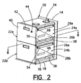
FIG. 2 is a perspective view of the file cabinet shown inFIG. 1 with a portion of its outer housing removed; -
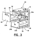
FIG. 3 is a perspective view of the file cabinet shown inFIG. 2 with the top drawer in an open position; -
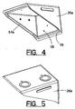
FIG. 4 is a bottom perspective view of a first cavity portion of the split-bodied insulated cavity; -
FIG. 5 is a top perspective view of the first cavity portion of the split-bodied insulated cavity shown inFIG. 4 ; -
FIG. 6 is a top perspective view of a second cavity portion of the split-bodied insulated cavity; -
FIG. 7 is a bottom perspective view of the second cavity portion of the split-bodied insulated cavity shown inFIG. 6 ; -
FIG. 8 is a cross-sectional view of a complete split-bodied insulated cavity installed in a closed drawer of a file cabinet taken along line 8-8 inFIG. 2 ; and -
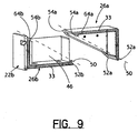
FIG. 9 is a cross-sectional view as shown inFIG. 8 with the drawer in an open position, showing a diagonal mating plane therebetween. - The exemplification set out herein illustrates one embodiment of the invention, in one form, and such exemplification is not to be construed as limiting the scope of the invention in any manner.
- Referring to the drawings in detail, and initially to
FIGS. 1-3 ,reference numeral 10 generally designates an exemplary file cabinet that may be used in conjunction with the present invention.File cabinet 10 may comprise anouter housing 11 including a pair ofopposing side walls 12, aback wall 14, atop wall 16, and abottom support base 18.Outer housing 11 may be formed of, for example, wood, plastic, or metal, such as aluminum.Side walls 12,top wall 16, andbottom support base 18 may define anopening 20 configured to allow at least one of first andsecond drawer assemblies - In accordance with the present invention, at least one of first and
second drawer assemblies resistant cavities file cabinet 10. Each split-bodied fire-resistant cavity second cavity portions file cabinet 10 from fire when therespective drawer assembly FIG. 8 , each of first andsecond cavity portions outer wall 28 and aninner wall 30 defining aninsulation space 32 therebetween. Withininsulation space 32 is a thermally insulative fire-resistant material 33, such as, for example, a hydrated Portland cement having between about 40-60% water content and including nylon fibers. While first andsecond cavity portions second cavity portions - As best seen in
FIGS. 2 and3 ,first cavity portion 26a may either be slidably or fixedly mounted toside walls 12 offile cabinet 10 using a pair ofmounting brackets 34.Second cavity portion 26b is mounted to one ofdrawer assemblies file cabinet 10 along with its respective drawer assembly. In particular, a pair oftracks 36 are mounted to opposite sides ofsecond cavity portion 26b, whereintracks 36 are configured to be slidably received within a corresponding pair ofchannels 38 that are mounted toside walls 12 offile cabinet 10. The interaction betweentracks 36 andchannels 38 allowdrawer assembly tracks 36 andchannels 38 described herein are conventional, and may be interchanged with other known drawer track configurations known in the art. Further, adrawer cover 40 may be fastened to a front portion ofsecond cavity portion 26b and provide ahandle 42 to assist a user with opening and closing thedrawer assembly locking assembly 44 also may be mounted to thedrawer assembly file cabinet 10. - In addition, an open-
ended storage box 46 may be positioned withinsecond cavity portion 26b to allow for papers, files, or other items to be stored therein.Storage box 46 may be formed of sheet metal, plastic, or some other suitable material that has storage capabilities.Second cavity portion 26b is configured to partially surroundstorage box 46 so that the inside ofstorage box 46 is accessible whendrawer assembly drawer assembly FIGS. 2 and8 , first andsecond cavity portions mating interface 48 to entirely surround open-ended storage box 46 and the contents located therein to form a localized insulated fire-resistant cavity. Becausemating interface 48 may be provided on a diagonal plane 50 (FIG. 9 ) extending generally from the lowerinner corners outer corners second cavity portions storage box 46 is fully accessible when arespective drawer assembly mating interface 48 is shown and described as being a diagonal mating surface, it should be understood that other non-diagonal mating surfaces are also within the scope of the present invention. - As best seen in
FIGS. 4-9 , eachfirst cavity portion 26a may include arecess 56 surroundingmating opening 58; and likewise, eachsecond cavity portion 26b may include amating ridge 60 surroundingmating opening 62. A water-resistant seal recess 56 andridge 60 andsurround openings FIG. 2 ). For example, water-resistant seal resistant seals mating interface 48 between first andsecond cavity portions - By providing a file cabinet including a split-bodied fire-resistant cavity in at least one of its file drawer assemblies, numerous advantages are realized. For example, the amount of thermally resistive insulation material that is necessary to protect the contents of the file drawer assembly is substantially less than in the prior art because the need to globally protect the entire housing of the file cabinet is eliminated. The split-bodied fire-resistant cavity allows for the selective use of fire protection for one of the file drawer assemblies, for example, where the other drawer assemblies in the file cabinet are not protected from fire, thereby reducing the amount of insulation material that is needed to manufacture the file cabinet. The present invention is not only less expensive to manufacture because it uses less fire-resistant insulation than in the prior art, but it also provides a local fire-rated space within an otherwise non-fire-rated file cabinet.
Claims (9)
- A localized split-bodied fire-resistant cavity (24a, 24b) for a file cabinet (10) having an outer housing (11) defining an opening (20) for slidably receiving at least one file drawer assembly (22a, 22b) therein, the split-bodied fire-resistant cavity (24a, 24b) characterized by :a first cavity portion (26a) configured to be mounted to the outer housing (11) of the file cabinet (10);a second cavity portion (26b) configured to be mounted to the file drawer assembly (22a, 22b); anda mating interface (48) between said first and second cavity portions (26a, 26b), wherein the mating interface is disposed on a diagonal plane (50), and wherein the first and second cavity portions (26a, 26b) are configure to join together at the mating interface (48) to define a localized fire-resistant space when the at least one file drawer assembly (26a, 26b) is in a closed position.
- A localized split-bodied fire-resistant cavity (24a, 24b) in accordance with claim 1, wherein at least one of the first and second cavity portions (26a, 26b) include an outer wall (28) and an inner wall (30) defining an insulation space (32) therebetween.
- A localized split-bodied fire-resistant cavity (24a, 24b) in accordance with claim 2, wherein a thermally insulative fire-resistant material (33) is positioned within the insulation space (32).
- A localized split-bodied fire-resistant cavity (24a, 24b) in accordance with Claim 1, further comprising an open-ended storage box (46) disposed within the second cavity portion (26b), wherein the second cavity portion (26b) is configured to surround a portion of the open-ended storage box (46), wherein the first and second cavity portions (26a, 26b) are configured to join together at the mating interface (48) to entirely surround the open-ended storage box (46) when the at least one file drawer assembly (22a, 22b) is in the closed position.
- A localized split-bodied fire-resistant cavity (24a, 24b) in accordance with Claim 3, wherein the open-ended storage box (48) is formed of sheet metal.
- A localized split-bodied fire-resistant cavity (24a, 24b) in accordance with Claim 1, wherein one of the first and second cavity portions (26a, 26b) includes a mating recess (56), and the other of the first and second cavity portions (26a, 26b) has a mating ridge (60) formed therein, wherein the mating ridge (60) is positioned within the mating recess (56) along the mating interface (48).
- A localized split-bodied fire-resistant cavity (24a, 24b) in accordance with claim 6, wherein a gasket (64a, 64b) is positioned within the mating recess (56).
- A localized split-bodied fire-resistant cavity (24a, 24b) in accordance with Claim 1, wherein the first cavity portion (26a) is configured to be fixedly mounted to the outer housing (11) of the file cabinet (10).
- A file cabinet (10) comprising:an outer housing (11) defining an opening (20);at least one file drawer assembly (22a, 22b) slidably disposed within the opening (20) of the outer housing (11), the at least one file drawer assembly (22a, 22b) including an open-ended storage box (48); anda split-bodied fire-resistant cavity (24a, 24b) as set forth in any one of claims 1 to 8, wherein the first cavity portion (26a) is mounted to the outer housing (11), wherein the second cavity portion (26b) is mounted to the file drawer assembly (22a, 22b) and is configured to surround a portion of the open-ended storage box (48), wherein the open-ended storage box (48) is accessible when the at least one file drawer assembly (22a, 22b) is in an open position, and wherein the first and second cavity portions (26a, 26b) are configured to join together at the mating interface to entirely surround the open-ended storage box (48) when the at least one file drawer assembly (22a, 22b) is in a closed position.
Applications Claiming Priority (1)
| Application Number | Priority Date | Filing Date | Title |
|---|---|---|---|
| US12/862,193 US8454104B2 (en) | 2010-08-24 | 2010-08-24 | Split-bodied insulated cavity for a file cabinet |
Publications (2)
| Publication Number | Publication Date |
|---|---|
| EP2422649A1 EP2422649A1 (en) | 2012-02-29 |
| EP2422649B1 true EP2422649B1 (en) | 2013-07-31 |
Family
ID=44508626
Family Applications (1)
| Application Number | Title | Priority Date | Filing Date |
|---|---|---|---|
| EP11006884.8A Not-in-force EP2422649B1 (en) | 2010-08-24 | 2011-08-23 | Split-bodied insulated cavity for a file cabinet |
Country Status (6)
| Country | Link |
|---|---|
| US (1) | US8454104B2 (en) |
| EP (1) | EP2422649B1 (en) |
| JP (1) | JP5705646B2 (en) |
| CN (1) | CN102370349B (en) |
| CA (1) | CA2745488A1 (en) |
| MX (1) | MX2011005606A (en) |
Families Citing this family (3)
| Publication number | Priority date | Publication date | Assignee | Title |
|---|---|---|---|---|
| US10094160B2 (en) | 2015-03-21 | 2018-10-09 | Michael B. DeBaldo | Tongue and groove modular fire safe |
| US10085554B2 (en) * | 2016-03-15 | 2018-10-02 | Robert A. Schooley, JR. | Gun cabinet |
| CN112353129B (en) * | 2020-11-09 | 2022-03-15 | 佳木斯大学 | Intelligent filing cabinet is deposited with archives to mathematical education |
Family Cites Families (22)
| Publication number | Priority date | Publication date | Assignee | Title |
|---|---|---|---|---|
| US1902795A (en) | 1930-08-30 | 1933-03-21 | Remington Rand Inc | Drawer suspension |
| GB489522A (en) | 1936-05-01 | 1938-07-28 | Remington Rand Inc | Improvements relating to articles of furniture provided with one or more drawers |
| US2333511A (en) * | 1941-10-02 | 1943-11-02 | Diebold Safe & Lock Company | Insulated filing cabinet manufacture and the like |
| US3095838A (en) * | 1960-09-30 | 1963-07-02 | Diebold Inc | Forced entry resistant security file construction |
| US3408966A (en) * | 1966-08-17 | 1968-11-05 | Desoto Inc | Fireproof container |
| JPS4832382Y1 (en) * | 1967-08-16 | 1973-10-03 | ||
| US3705754A (en) * | 1970-02-16 | 1972-12-12 | Hon Ind Inc | Filing units |
| US3817589A (en) * | 1972-11-06 | 1974-06-18 | Shaw Walker Co | Lateral fire resistant file cabinet |
| US3826552A (en) * | 1973-01-29 | 1974-07-30 | Shaw Walker Co | Insulated tape file |
| US3855741A (en) * | 1973-04-12 | 1974-12-24 | Gen Electric | Closure for fire resistant structure |
| US3888557A (en) * | 1974-02-28 | 1975-06-10 | Shaw Walker Co | Insulated inner container for a fire resistant file cabinet |
| US4303286A (en) * | 1980-01-28 | 1981-12-01 | Meilink Industries, Inc. | Insulated filing cabinet |
| CH646541A5 (en) * | 1980-03-18 | 1984-11-30 | Sistemco Nv | FIRE-SAFE CABINET AND METHOD FOR THE PRODUCTION THEREOF. |
| GB8524975D0 (en) * | 1985-10-10 | 1985-11-13 | Atomic Energy Authority Uk | Fire resistant panel |
| GB8628424D0 (en) * | 1986-11-27 | 1986-12-31 | Micropore International Ltd | Fire-resistant container |
| US5152231A (en) * | 1991-01-30 | 1992-10-06 | John D. Brush & Co., Inc. | Fire-resistant safe |
| GB2299260A (en) | 1995-03-28 | 1996-10-02 | Stephen Paul Goodacre | Drawer with security compartment |
| JPH08326421A (en) * | 1995-06-01 | 1996-12-10 | Misawa Homes Co Ltd | Storage furniture |
| JP3968612B2 (en) * | 1998-01-27 | 2007-08-29 | 三菱電機株式会社 | FULL VACUUM INSULATION BOX, REFRIGERATOR USING THE VACUUM VACUUM INSULATION BOX, METHOD FOR PRODUCING THE FULL VACUUM INSULATION BOX, AND METHOD OF DECOMPOSING |
| US20040150306A1 (en) * | 2000-05-17 | 2004-08-05 | Steedly John W. | Portable display, storage and transport case |
| TW200509836A (en) * | 2003-04-23 | 2005-03-16 | Brush & Co John D | Stackable blow molded cabinet |
| US7628113B2 (en) * | 2007-04-18 | 2009-12-08 | John D. Brush & Co., Inc. | Water-resistant liner for a safe |
-
2010
- 2010-08-24 US US12/862,193 patent/US8454104B2/en not_active Expired - Fee Related
-
2011
- 2011-05-13 JP JP2011108299A patent/JP5705646B2/en not_active Expired - Fee Related
- 2011-05-26 MX MX2011005606A patent/MX2011005606A/en active IP Right Grant
- 2011-05-30 CN CN201110156875.7A patent/CN102370349B/en not_active Expired - Fee Related
- 2011-07-06 CA CA2745488A patent/CA2745488A1/en not_active Abandoned
- 2011-08-23 EP EP11006884.8A patent/EP2422649B1/en not_active Not-in-force
Also Published As
| Publication number | Publication date |
|---|---|
| CA2745488A1 (en) | 2012-02-24 |
| JP5705646B2 (en) | 2015-04-22 |
| EP2422649A1 (en) | 2012-02-29 |
| US8454104B2 (en) | 2013-06-04 |
| MX2011005606A (en) | 2012-02-23 |
| CN102370349B (en) | 2014-11-05 |
| CN102370349A (en) | 2012-03-14 |
| US20120049714A1 (en) | 2012-03-01 |
| JP2012045371A (en) | 2012-03-08 |
Similar Documents
| Publication | Publication Date | Title |
|---|---|---|
| WO2003043891B1 (en) | Fire-resistant cabinet | |
| CA2273476C (en) | Refrigerator door corner construction | |
| US10098456B2 (en) | Built-in electrical household appliance and household appliance assembly and built-in furniture unit for a household appliance | |
| EP2422649B1 (en) | Split-bodied insulated cavity for a file cabinet | |
| WO2003063649B1 (en) | Fire-resistant gun cabinet | |
| US4252387A (en) | Storage chest with hidden compartment | |
| US5813739A (en) | Flammable material storage cabinet | |
| US9622575B2 (en) | Storage cabinet having a locking bar and method for securing the same | |
| US20060103275A1 (en) | Jewelry chest with a fully locking system | |
| US20100180646A1 (en) | Dual lock box | |
| US20050253490A1 (en) | Filing cabinet with waterproof seal | |
| US20100270896A1 (en) | Undercounter safety cabinet | |
| KR101483496B1 (en) | The storage case of cosmetics | |
| CN207383746U (en) | A kind of multi-functional equipment storage box | |
| CN209031478U (en) | A kind of secrecy stagewise file cabinet | |
| JP3183173B2 (en) | Cabinet structure | |
| CN208544632U (en) | A kind of cabinet with seal shock-proof function | |
| KR101346556B1 (en) | Dual storage cabinet papers | |
| US6331090B1 (en) | Device for connecting containers | |
| CN215993202U (en) | Filing cabinet is used in architectural design consultation | |
| KR200407874Y1 (en) | Strongbox for corner establishment | |
| US20210298474A1 (en) | Waterproof and Fire-resistant Storage Device | |
| WO2022153378A1 (en) | Refrigerator | |
| JPH0226348Y2 (en) | ||
| KR200295145Y1 (en) | a reading room desk |
Legal Events
| Date | Code | Title | Description |
|---|---|---|---|
| AK | Designated contracting states |
Kind code of ref document: A1 Designated state(s): AL AT BE BG CH CY CZ DE DK EE ES FI FR GB GR HR HU IE IS IT LI LT LU LV MC MK MT NL NO PL PT RO RS SE SI SK SM TR |
|
| AX | Request for extension of the european patent |
Extension state: BA ME |
|
| PUAI | Public reference made under article 153(3) epc to a published international application that has entered the european phase |
Free format text: ORIGINAL CODE: 0009012 |
|
| 17P | Request for examination filed |
Effective date: 20120822 |
|
| RIC1 | Information provided on ipc code assigned before grant |
Ipc: A47B 88/00 20060101AFI20121010BHEP |
|
| GRAP | Despatch of communication of intention to grant a patent |
Free format text: ORIGINAL CODE: EPIDOSNIGR1 |
|
| RAP1 | Party data changed (applicant data changed or rights of an application transferred) |
Owner name: JOHN D. BRUSH & CO., INC. |
|
| RIN1 | Information on inventor provided before grant (corrected) |
Inventor name: PALLO, R. DAVID |
|
| GRAS | Grant fee paid |
Free format text: ORIGINAL CODE: EPIDOSNIGR3 |
|
| GRAA | (expected) grant |
Free format text: ORIGINAL CODE: 0009210 |
|
| AK | Designated contracting states |
Kind code of ref document: B1 Designated state(s): AL AT BE BG CH CY CZ DE DK EE ES FI FR GB GR HR HU IE IS IT LI LT LU LV MC MK MT NL NO PL PT RO RS SE SI SK SM TR |
|
| REG | Reference to a national code |
Ref country code: GB Ref legal event code: FG4D Ref country code: CH Ref legal event code: EP |
|
| REG | Reference to a national code |
Ref country code: AT Ref legal event code: REF Ref document number: 624104 Country of ref document: AT Kind code of ref document: T Effective date: 20130815 |
|
| REG | Reference to a national code |
Ref country code: IE Ref legal event code: FG4D |
|
| REG | Reference to a national code |
Ref country code: DE Ref legal event code: R096 Ref document number: 602011002486 Country of ref document: DE Effective date: 20130926 |
|
| REG | Reference to a national code |
Ref country code: AT Ref legal event code: MK05 Ref document number: 624104 Country of ref document: AT Kind code of ref document: T Effective date: 20130731 |
|
| REG | Reference to a national code |
Ref country code: NL Ref legal event code: VDEP Effective date: 20130731 |
|
| REG | Reference to a national code |
Ref country code: LT Ref legal event code: MG4D |
|
| PG25 | Lapsed in a contracting state [announced via postgrant information from national office to epo] |
Ref country code: LT Free format text: LAPSE BECAUSE OF FAILURE TO SUBMIT A TRANSLATION OF THE DESCRIPTION OR TO PAY THE FEE WITHIN THE PRESCRIBED TIME-LIMIT Effective date: 20130731 Ref country code: BE Free format text: LAPSE BECAUSE OF FAILURE TO SUBMIT A TRANSLATION OF THE DESCRIPTION OR TO PAY THE FEE WITHIN THE PRESCRIBED TIME-LIMIT Effective date: 20130731 Ref country code: NO Free format text: LAPSE BECAUSE OF FAILURE TO SUBMIT A TRANSLATION OF THE DESCRIPTION OR TO PAY THE FEE WITHIN THE PRESCRIBED TIME-LIMIT Effective date: 20131031 Ref country code: AT Free format text: LAPSE BECAUSE OF FAILURE TO SUBMIT A TRANSLATION OF THE DESCRIPTION OR TO PAY THE FEE WITHIN THE PRESCRIBED TIME-LIMIT Effective date: 20130731 Ref country code: CY Free format text: LAPSE BECAUSE OF FAILURE TO SUBMIT A TRANSLATION OF THE DESCRIPTION OR TO PAY THE FEE WITHIN THE PRESCRIBED TIME-LIMIT Effective date: 20130814 Ref country code: HR Free format text: LAPSE BECAUSE OF FAILURE TO SUBMIT A TRANSLATION OF THE DESCRIPTION OR TO PAY THE FEE WITHIN THE PRESCRIBED TIME-LIMIT Effective date: 20130731 Ref country code: PT Free format text: LAPSE BECAUSE OF FAILURE TO SUBMIT A TRANSLATION OF THE DESCRIPTION OR TO PAY THE FEE WITHIN THE PRESCRIBED TIME-LIMIT Effective date: 20131202 Ref country code: IS Free format text: LAPSE BECAUSE OF FAILURE TO SUBMIT A TRANSLATION OF THE DESCRIPTION OR TO PAY THE FEE WITHIN THE PRESCRIBED TIME-LIMIT Effective date: 20131130 Ref country code: SE Free format text: LAPSE BECAUSE OF FAILURE TO SUBMIT A TRANSLATION OF THE DESCRIPTION OR TO PAY THE FEE WITHIN THE PRESCRIBED TIME-LIMIT Effective date: 20130731 |
|
| PG25 | Lapsed in a contracting state [announced via postgrant information from national office to epo] |
Ref country code: GR Free format text: LAPSE BECAUSE OF FAILURE TO SUBMIT A TRANSLATION OF THE DESCRIPTION OR TO PAY THE FEE WITHIN THE PRESCRIBED TIME-LIMIT Effective date: 20131101 Ref country code: FI Free format text: LAPSE BECAUSE OF FAILURE TO SUBMIT A TRANSLATION OF THE DESCRIPTION OR TO PAY THE FEE WITHIN THE PRESCRIBED TIME-LIMIT Effective date: 20130731 Ref country code: PL Free format text: LAPSE BECAUSE OF FAILURE TO SUBMIT A TRANSLATION OF THE DESCRIPTION OR TO PAY THE FEE WITHIN THE PRESCRIBED TIME-LIMIT Effective date: 20130731 Ref country code: LV Free format text: LAPSE BECAUSE OF FAILURE TO SUBMIT A TRANSLATION OF THE DESCRIPTION OR TO PAY THE FEE WITHIN THE PRESCRIBED TIME-LIMIT Effective date: 20130731 Ref country code: NL Free format text: LAPSE BECAUSE OF FAILURE TO SUBMIT A TRANSLATION OF THE DESCRIPTION OR TO PAY THE FEE WITHIN THE PRESCRIBED TIME-LIMIT Effective date: 20130731 Ref country code: SI Free format text: LAPSE BECAUSE OF FAILURE TO SUBMIT A TRANSLATION OF THE DESCRIPTION OR TO PAY THE FEE WITHIN THE PRESCRIBED TIME-LIMIT Effective date: 20130731 |
|
| PG25 | Lapsed in a contracting state [announced via postgrant information from national office to epo] |
Ref country code: CY Free format text: LAPSE BECAUSE OF FAILURE TO SUBMIT A TRANSLATION OF THE DESCRIPTION OR TO PAY THE FEE WITHIN THE PRESCRIBED TIME-LIMIT Effective date: 20130731 |
|
| PG25 | Lapsed in a contracting state [announced via postgrant information from national office to epo] |
Ref country code: MC Free format text: LAPSE BECAUSE OF FAILURE TO SUBMIT A TRANSLATION OF THE DESCRIPTION OR TO PAY THE FEE WITHIN THE PRESCRIBED TIME-LIMIT Effective date: 20130731 Ref country code: DK Free format text: LAPSE BECAUSE OF FAILURE TO SUBMIT A TRANSLATION OF THE DESCRIPTION OR TO PAY THE FEE WITHIN THE PRESCRIBED TIME-LIMIT Effective date: 20130731 Ref country code: SK Free format text: LAPSE BECAUSE OF FAILURE TO SUBMIT A TRANSLATION OF THE DESCRIPTION OR TO PAY THE FEE WITHIN THE PRESCRIBED TIME-LIMIT Effective date: 20130731 Ref country code: EE Free format text: LAPSE BECAUSE OF FAILURE TO SUBMIT A TRANSLATION OF THE DESCRIPTION OR TO PAY THE FEE WITHIN THE PRESCRIBED TIME-LIMIT Effective date: 20130731 Ref country code: RO Free format text: LAPSE BECAUSE OF FAILURE TO SUBMIT A TRANSLATION OF THE DESCRIPTION OR TO PAY THE FEE WITHIN THE PRESCRIBED TIME-LIMIT Effective date: 20130731 Ref country code: DE Free format text: LAPSE BECAUSE OF NON-PAYMENT OF DUE FEES Effective date: 20140301 Ref country code: CZ Free format text: LAPSE BECAUSE OF FAILURE TO SUBMIT A TRANSLATION OF THE DESCRIPTION OR TO PAY THE FEE WITHIN THE PRESCRIBED TIME-LIMIT Effective date: 20130731 |
|
| REG | Reference to a national code |
Ref country code: IE Ref legal event code: MM4A |
|
| REG | Reference to a national code |
Ref country code: DE Ref legal event code: R119 Ref document number: 602011002486 Country of ref document: DE Effective date: 20140301 |
|
| PG25 | Lapsed in a contracting state [announced via postgrant information from national office to epo] |
Ref country code: IT Free format text: LAPSE BECAUSE OF FAILURE TO SUBMIT A TRANSLATION OF THE DESCRIPTION OR TO PAY THE FEE WITHIN THE PRESCRIBED TIME-LIMIT Effective date: 20130731 Ref country code: ES Free format text: LAPSE BECAUSE OF FAILURE TO SUBMIT A TRANSLATION OF THE DESCRIPTION OR TO PAY THE FEE WITHIN THE PRESCRIBED TIME-LIMIT Effective date: 20130731 |
|
| PLBE | No opposition filed within time limit |
Free format text: ORIGINAL CODE: 0009261 |
|
| STAA | Information on the status of an ep patent application or granted ep patent |
Free format text: STATUS: NO OPPOSITION FILED WITHIN TIME LIMIT |
|
| 26N | No opposition filed |
Effective date: 20140502 |
|
| REG | Reference to a national code |
Ref country code: FR Ref legal event code: ST Effective date: 20140618 |
|
| PG25 | Lapsed in a contracting state [announced via postgrant information from national office to epo] |
Ref country code: IE Free format text: LAPSE BECAUSE OF NON-PAYMENT OF DUE FEES Effective date: 20130823 |
|
| PG25 | Lapsed in a contracting state [announced via postgrant information from national office to epo] |
Ref country code: FR Free format text: LAPSE BECAUSE OF NON-PAYMENT OF DUE FEES Effective date: 20130930 |
|
| REG | Reference to a national code |
Ref country code: CH Ref legal event code: PL |
|
| PG25 | Lapsed in a contracting state [announced via postgrant information from national office to epo] |
Ref country code: CH Free format text: LAPSE BECAUSE OF NON-PAYMENT OF DUE FEES Effective date: 20140831 Ref country code: LI Free format text: LAPSE BECAUSE OF NON-PAYMENT OF DUE FEES Effective date: 20140831 |
|
| PG25 | Lapsed in a contracting state [announced via postgrant information from national office to epo] |
Ref country code: SM Free format text: LAPSE BECAUSE OF FAILURE TO SUBMIT A TRANSLATION OF THE DESCRIPTION OR TO PAY THE FEE WITHIN THE PRESCRIBED TIME-LIMIT Effective date: 20130731 |
|
| PG25 | Lapsed in a contracting state [announced via postgrant information from national office to epo] |
Ref country code: TR Free format text: LAPSE BECAUSE OF FAILURE TO SUBMIT A TRANSLATION OF THE DESCRIPTION OR TO PAY THE FEE WITHIN THE PRESCRIBED TIME-LIMIT Effective date: 20130731 Ref country code: MT Free format text: LAPSE BECAUSE OF FAILURE TO SUBMIT A TRANSLATION OF THE DESCRIPTION OR TO PAY THE FEE WITHIN THE PRESCRIBED TIME-LIMIT Effective date: 20130731 |
|
| PG25 | Lapsed in a contracting state [announced via postgrant information from national office to epo] |
Ref country code: RS Free format text: LAPSE BECAUSE OF FAILURE TO SUBMIT A TRANSLATION OF THE DESCRIPTION OR TO PAY THE FEE WITHIN THE PRESCRIBED TIME-LIMIT Effective date: 20131031 Ref country code: MK Free format text: LAPSE BECAUSE OF FAILURE TO SUBMIT A TRANSLATION OF THE DESCRIPTION OR TO PAY THE FEE WITHIN THE PRESCRIBED TIME-LIMIT Effective date: 20130731 Ref country code: BG Free format text: LAPSE BECAUSE OF FAILURE TO SUBMIT A TRANSLATION OF THE DESCRIPTION OR TO PAY THE FEE WITHIN THE PRESCRIBED TIME-LIMIT Effective date: 20130731 Ref country code: HU Free format text: LAPSE BECAUSE OF FAILURE TO SUBMIT A TRANSLATION OF THE DESCRIPTION OR TO PAY THE FEE WITHIN THE PRESCRIBED TIME-LIMIT; INVALID AB INITIO Effective date: 20110823 Ref country code: LU Free format text: LAPSE BECAUSE OF NON-PAYMENT OF DUE FEES Effective date: 20130823 |
|
| PGFP | Annual fee paid to national office [announced via postgrant information from national office to epo] |
Ref country code: GB Payment date: 20170829 Year of fee payment: 7 |
|
| PG25 | Lapsed in a contracting state [announced via postgrant information from national office to epo] |
Ref country code: AL Free format text: LAPSE BECAUSE OF FAILURE TO SUBMIT A TRANSLATION OF THE DESCRIPTION OR TO PAY THE FEE WITHIN THE PRESCRIBED TIME-LIMIT Effective date: 20130731 |
|
| GBPC | Gb: european patent ceased through non-payment of renewal fee |
Effective date: 20180823 |
|
| PG25 | Lapsed in a contracting state [announced via postgrant information from national office to epo] |
Ref country code: GB Free format text: LAPSE BECAUSE OF NON-PAYMENT OF DUE FEES Effective date: 20180823 |