JP5703573B2 - Secondary battery - Google Patents
Secondary battery Download PDFInfo
- Publication number
- JP5703573B2 JP5703573B2 JP2010058224A JP2010058224A JP5703573B2 JP 5703573 B2 JP5703573 B2 JP 5703573B2 JP 2010058224 A JP2010058224 A JP 2010058224A JP 2010058224 A JP2010058224 A JP 2010058224A JP 5703573 B2 JP5703573 B2 JP 5703573B2
- Authority
- JP
- Japan
- Prior art keywords
- safety valve
- battery
- cover plate
- groove pattern
- center
- Prior art date
- Legal status (The legal status is an assumption and is not a legal conclusion. Google has not performed a legal analysis and makes no representation as to the accuracy of the status listed.)
- Expired - Fee Related
Links
Images


Classifications
-
- H—ELECTRICITY
- H01—ELECTRIC ELEMENTS
- H01M—PROCESSES OR MEANS, e.g. BATTERIES, FOR THE DIRECT CONVERSION OF CHEMICAL ENERGY INTO ELECTRICAL ENERGY
- H01M50/00—Constructional details or processes of manufacture of the non-active parts of electrochemical cells other than fuel cells, e.g. hybrid cells
- H01M50/10—Primary casings, jackets or wrappings of a single cell or a single battery
- H01M50/147—Lids or covers
-
- H—ELECTRICITY
- H01—ELECTRIC ELEMENTS
- H01M—PROCESSES OR MEANS, e.g. BATTERIES, FOR THE DIRECT CONVERSION OF CHEMICAL ENERGY INTO ELECTRICAL ENERGY
- H01M10/00—Secondary cells; Manufacture thereof
- H01M10/05—Accumulators with non-aqueous electrolyte
- H01M10/052—Li-accumulators
- H01M10/0525—Rocking-chair batteries, i.e. batteries with lithium insertion or intercalation in both electrodes; Lithium-ion batteries
-
- H—ELECTRICITY
- H01—ELECTRIC ELEMENTS
- H01M—PROCESSES OR MEANS, e.g. BATTERIES, FOR THE DIRECT CONVERSION OF CHEMICAL ENERGY INTO ELECTRICAL ENERGY
- H01M50/00—Constructional details or processes of manufacture of the non-active parts of electrochemical cells other than fuel cells, e.g. hybrid cells
- H01M50/10—Primary casings, jackets or wrappings of a single cell or a single battery
- H01M50/102—Primary casings, jackets or wrappings of a single cell or a single battery characterised by their shape or physical structure
- H01M50/103—Primary casings, jackets or wrappings of a single cell or a single battery characterised by their shape or physical structure prismatic or rectangular
-
- H—ELECTRICITY
- H01—ELECTRIC ELEMENTS
- H01M—PROCESSES OR MEANS, e.g. BATTERIES, FOR THE DIRECT CONVERSION OF CHEMICAL ENERGY INTO ELECTRICAL ENERGY
- H01M50/00—Constructional details or processes of manufacture of the non-active parts of electrochemical cells other than fuel cells, e.g. hybrid cells
- H01M50/30—Arrangements for facilitating escape of gases
- H01M50/342—Non-re-sealable arrangements
- H01M50/3425—Non-re-sealable arrangements in the form of rupturable membranes or weakened parts, e.g. pierced with the aid of a sharp member
-
- H—ELECTRICITY
- H01—ELECTRIC ELEMENTS
- H01M—PROCESSES OR MEANS, e.g. BATTERIES, FOR THE DIRECT CONVERSION OF CHEMICAL ENERGY INTO ELECTRICAL ENERGY
- H01M50/00—Constructional details or processes of manufacture of the non-active parts of electrochemical cells other than fuel cells, e.g. hybrid cells
- H01M50/50—Current conducting connections for cells or batteries
- H01M50/543—Terminals
-
- H—ELECTRICITY
- H01—ELECTRIC ELEMENTS
- H01M—PROCESSES OR MEANS, e.g. BATTERIES, FOR THE DIRECT CONVERSION OF CHEMICAL ENERGY INTO ELECTRICAL ENERGY
- H01M2220/00—Batteries for particular applications
- H01M2220/20—Batteries in motive systems, e.g. vehicle, ship, plane
-
- Y—GENERAL TAGGING OF NEW TECHNOLOGICAL DEVELOPMENTS; GENERAL TAGGING OF CROSS-SECTIONAL TECHNOLOGIES SPANNING OVER SEVERAL SECTIONS OF THE IPC; TECHNICAL SUBJECTS COVERED BY FORMER USPC CROSS-REFERENCE ART COLLECTIONS [XRACs] AND DIGESTS
- Y02—TECHNOLOGIES OR APPLICATIONS FOR MITIGATION OR ADAPTATION AGAINST CLIMATE CHANGE
- Y02E—REDUCTION OF GREENHOUSE GAS [GHG] EMISSIONS, RELATED TO ENERGY GENERATION, TRANSMISSION OR DISTRIBUTION
- Y02E60/00—Enabling technologies; Technologies with a potential or indirect contribution to GHG emissions mitigation
- Y02E60/10—Energy storage using batteries
-
- Y—GENERAL TAGGING OF NEW TECHNOLOGICAL DEVELOPMENTS; GENERAL TAGGING OF CROSS-SECTIONAL TECHNOLOGIES SPANNING OVER SEVERAL SECTIONS OF THE IPC; TECHNICAL SUBJECTS COVERED BY FORMER USPC CROSS-REFERENCE ART COLLECTIONS [XRACs] AND DIGESTS
- Y02—TECHNOLOGIES OR APPLICATIONS FOR MITIGATION OR ADAPTATION AGAINST CLIMATE CHANGE
- Y02P—CLIMATE CHANGE MITIGATION TECHNOLOGIES IN THE PRODUCTION OR PROCESSING OF GOODS
- Y02P70/00—Climate change mitigation technologies in the production process for final industrial or consumer products
- Y02P70/50—Manufacturing or production processes characterised by the final manufactured product
-
- Y—GENERAL TAGGING OF NEW TECHNOLOGICAL DEVELOPMENTS; GENERAL TAGGING OF CROSS-SECTIONAL TECHNOLOGIES SPANNING OVER SEVERAL SECTIONS OF THE IPC; TECHNICAL SUBJECTS COVERED BY FORMER USPC CROSS-REFERENCE ART COLLECTIONS [XRACs] AND DIGESTS
- Y02—TECHNOLOGIES OR APPLICATIONS FOR MITIGATION OR ADAPTATION AGAINST CLIMATE CHANGE
- Y02T—CLIMATE CHANGE MITIGATION TECHNOLOGIES RELATED TO TRANSPORTATION
- Y02T10/00—Road transport of goods or passengers
- Y02T10/60—Other road transportation technologies with climate change mitigation effect
- Y02T10/70—Energy storage systems for electromobility, e.g. batteries
Description
本発明は、安全弁を有する二次電池に関する。 The present invention relates to a secondary battery having a safety valve.
近年、環境問題を背景にして、ハイブリッド電気自動車(HEV)、電気自動車(EV)、フォークリフト、ショベルカー等の移動体のみならず、UPS(無停電電源装置)、太陽光発電の電力貯蔵などの産業用用途にも、リチウムイオン電池を代表とする二次電池
の適用が図られている。このような二次電池の用途拡大に伴って、大容量化、高エネルギー密度化が求められている。
In recent years, against the background of environmental issues, not only mobile objects such as hybrid electric vehicles (HEV), electric vehicles (EV), forklifts, excavators, but also UPS (uninterruptible power supply), solar power generation power storage, etc. Secondary batteries typified by lithium ion batteries are also being applied to industrial applications. Along with the expansion of applications of such secondary batteries, there is a demand for higher capacity and higher energy density.
また、これら高性能化に加えて、高安全性化も重要な課題となっている。二次電池としては、ニッケルカドミウム電池、ニッケル水素電池、リチウムイオン電池等がある。ニッケルカドミウム電池はカドミウムが有毒であることなどから、ニッケル水素電池やリチウムイオン電池への転換が進んでいる。現存する二次電池の中でも、特にリチウムイオン二次電池は高エネルギー密度化に適しており、現在でもその開発が盛んに進められている。 In addition to these higher performances, higher safety is also an important issue. Secondary batteries include nickel cadmium batteries, nickel metal hydride batteries, lithium ion batteries, and the like. Nickel cadmium batteries are being converted to nickel metal hydride batteries and lithium ion batteries because cadmium is toxic. Among the existing secondary batteries, the lithium ion secondary battery is particularly suitable for increasing the energy density, and its development is being actively promoted.
このニッケル水素電池やリチウムイオン二次電池の主要な構成は、表面に負極活物質層を形成した金属集電体(負極)と、電解質を保持するセパレータと、表面に正極活物質層を形成した他の金属集電体(正極)である。ニッケル水素電池は、正極にニッケル酸化物、負極に水素吸蔵合金を採用している。また、リチウムイオン二次電池は、正極にリチウム金属酸化物、負極に黒鉛などのカーボン材料を採用している。電池構造としては、帯状の負極、セパレータ、正極を順次渦巻き状に巻いた円筒型構造と、短冊状の負極、セパレータ、正極を交互に配置した積層体からなる積層型構造とに大別される。帯状の負極、セパレータ、正極を巻き取るための軸芯等の発電に関与しない体積部分が多くある円筒型構造よりも、短冊状の負極、セパレータ、正極を交互に配置した積層型構造の方が、一般的に高体積エネルギー密度化に適している。これは、積層型は、巻取りのための軸芯が不要であることや、外部出力用の正極及び負極端子を同一面に形成し易いことから、発電に寄与する部分以外の体積を少なくできるからである。このような二次電池の電池缶は、金属集電体を収納する缶本体と外部出力用の正極及び負極端子を有する蓋板で密閉されている。 The main components of the nickel metal hydride battery and the lithium ion secondary battery are as follows: a metal current collector (negative electrode) having a negative electrode active material layer formed on the surface, a separator for holding an electrolyte, and a positive electrode active material layer formed on the surface. Another metal current collector (positive electrode). The nickel metal hydride battery employs nickel oxide for the positive electrode and a hydrogen storage alloy for the negative electrode. In addition, lithium ion secondary batteries employ a lithium metal oxide for the positive electrode and a carbon material such as graphite for the negative electrode. Battery structures are broadly divided into a cylindrical structure in which strip-shaped negative electrodes, separators, and positive electrodes are sequentially wound in a spiral manner, and a stacked structure composed of a laminate in which strip-shaped negative electrodes, separators, and positive electrodes are alternately arranged. . A laminated structure in which strip-shaped negative electrodes, separators, and positive electrodes are alternately arranged is more preferable than a cylindrical structure in which there are many volume portions that are not involved in power generation, such as a belt-shaped negative electrode, separator, and positive shaft. Generally, it is suitable for high volume energy density. This is because the laminated type does not require an axis for winding, and it is easy to form a positive electrode and a negative electrode terminal for external output on the same surface, so the volume other than the portion that contributes to power generation can be reduced. Because. The battery can of such a secondary battery is sealed with a lid plate having a can main body that houses a metal current collector, and a positive electrode and a negative electrode terminal for external output.
従来一般的にこのような二次電池の組立は、外装缶に蓋板で封止する前に、外部出力用の正極及び負極端子と、負極、セパレータ、正極からなる電極群との電気的接続を行う。外部出力用の正極及び負極端子は、端子本体と端子本体の基部に形成された端子基体部とを備えている。電池缶外部に露出している部分を端子本体と呼び、電池缶内部に納まっている部分を端子基体部と呼ぶ。通常、この端子基体部において、電極群との電気接続を行う。その後、外部出力用の正極及び負極端子と電極群が組みつけられて一体となった積層体は、端子本体が蓋板の開口部に絶縁性部材を介して取り付けられる。この積層体を電池缶本体の開口部に挿入後、蓋板と缶本体を封止する。缶本体の中では、積層体の構成要素であるセパレータ、正極、負極が電解液で含浸されている。そして、安全性を確保するため、安全弁などの安全機構部が付与されている。エネルギー密度が高い大容量の電池は、過充電等の誤使用や異物の混入などによる短絡等によって、従来の電池に比べて、破裂、発火等が生じた場合の被害規模が大きくなる。 Conventionally, the assembly of such a secondary battery is generally performed by electrically connecting a positive electrode and a negative electrode terminal for external output to an electrode group including a negative electrode, a separator, and a positive electrode before sealing the outer can with a cover plate. I do. A positive electrode and a negative electrode terminal for external output include a terminal body and a terminal base part formed at the base of the terminal body. The portion exposed to the outside of the battery can is called a terminal body, and the portion housed inside the battery can is called a terminal base portion. Usually, in this terminal base part, electrical connection with the electrode group is performed. After that, in the laminated body in which the positive and negative terminals for external output and the electrode group are assembled together , the terminal body is attached to the opening of the lid plate via an insulating member. After inserting a laminate of this the opening of the battery can body to seal the cover plate and the can body. In the can main body , the separator, the positive electrode, and the negative electrode, which are constituent elements of the laminate, are impregnated with the electrolytic solution. And in order to ensure safety, safety mechanism parts, such as a safety valve, are provided. A large-capacity battery with a high energy density has a greater damage scale when a burst, ignition, or the like occurs due to misuse such as overcharging or short-circuiting due to foreign matters.
従来の安全弁は、例えば、特許文献1のように、正極及び負極端子と同じ平面にある蓋板に配置されたものや、特許文献2のように、電池缶側面に安全弁を配置したものなどが提案されている。また、安全弁が動作した際に、発生したガスがスムースに電池缶外へ排出できるように、特許文献2では、ガス抜き孔(安全弁)が渦巻電極群の捲回面の投影した電池缶面内にあることで、発生するガスが巻軸に沿ってスムースに、電池缶側壁に設けたガス抜き孔を通して、電池外へ排出されることが記載されている。また、特許文献3には、円筒形電池において、円板状の封口板の中央に極柱を配置し、極柱の外周面における防爆弁の配置方向とは異なった周方向位置にリードの接合面を設けて、複数の防爆弁とリードを、封口板に対して垂直方向から見て相互に重ならない位置に配置することが記載されている。
Conventional safety valves include, for example, those arranged on a cover plate in the same plane as the positive and negative terminals as in
大容量電池の場合、破裂した際のガス放出量も多くなるため、安全弁の面積(「安全弁の動作時における開口部の面積」を意味する。以下同様。)をなるべく大きく取ることが必要である。安全弁の面積が電池容量に対して小さ過ぎると、生成ガス量に対して電池缶外に放出されるガス量が小さいため、安全弁が作動しても電池缶の内圧上昇が止まらず、電池缶自体の破損に至る恐れがある。また、電池缶内部で生成ガスの流れが妨げられて滞留し内圧上昇を招かないように、正極、負極、セパレータからなる金属集電板群及び端子本体と端子本体の基部に形成された端子基体部を備えた通電部品と安全弁の配置関係に配慮が必要である。高い内圧で破損するほど、破損時の衝撃などにより、周囲環境に及ぼす影響が大きくなる。よって、大容量化するほど、安全弁の面積は広くとるとともに、電池缶内部のガス流れをスムースにする必要がある。 In the case of a large-capacity battery, the amount of gas released when it ruptures also increases, so it is necessary to make the area of the safety valve (which means “the area of the opening during the operation of the safety valve”, the same applies hereinafter) as large as possible . . If the area of the safety valve is too small for the battery capacity, the amount of gas released outside the battery can is small relative to the amount of generated gas. There is a risk of damage. Also, a metal base plate group consisting of a positive electrode, a negative electrode, and a separator, and a terminal base formed on the base of the terminal body and the terminal body so that the flow of the product gas is hindered and stays inside the battery can and does not increase the internal pressure. Consideration should be given to the relationship between the current-carrying parts equipped with the part and the safety valve. The higher the internal pressure, the greater the impact on the surrounding environment due to impact at the time of failure. Therefore, the larger the capacity, the larger the area of the safety valve and the smoother the gas flow inside the battery can.
また、大容量電池の放電時の温度上昇を抑えるため、外部出力用の正極及び負極端子、すなわち上記の通電部品を大きくする必要がある。これは、大容量になるほど、放電時の電流が大きくなるため、通電部品の電気抵抗を小さくしないと、通電部品部分での発熱が増大し、電池の許容安全温度までの余裕が少なくなってしまうからである。このように、二次電池の大容量化に伴い安全弁や通電部品の大型化といった課題がある。 In addition, in order to suppress the temperature rise during the discharge of a large capacity battery, the positive electrode and the negative electrode terminal for external output, it is necessary to increase the energization part. This is because as becomes large, because the current during the discharge becomes large, unless reduced the electrical resistance of conductible parts, heat generation is increased in the energization part portion, it becomes small margin to an acceptable safe temperature of the battery Because it ends up. As described above, there is a problem that the safety valve and energized parts are increased in size as the capacity of the secondary battery is increased.
一方、エネルギー密度を高めるためには、なるべく電池体積を小さくする必要があり、発電要素以外、すなわち、安全弁や通電部品はなるべく小さくする必要がある。このように、大容量電池において、大容量化と高エネルギー密度化の両方に対応するためには、安全弁や通電部品の大きさに対して相反する要求がある。特に、100Ah以上の大容量の電池の場合、蓄えられているエネルギー量が大きいことから、電池はコンパクトでありながら、安全弁はなるべく大きいことが望まれる。 Meanwhile, in order to increase the energy density, it is necessary to reduce as much as possible of cell volume, except power generating element, namely, the safety valve and conductible parts should be as small as possible. Thus, in a large capacity battery, in order to accommodate both a large capacity and high energy density, it is contradictory requirements with respect to the safety valve and conductible parts size. In particular, in the case of a battery with a large capacity of 100 Ah or more, since the amount of stored energy is large, it is desired that the safety valve be as large as possible while the battery is compact.
エネルギー密度を高めるためには、特許文献1のように、安全弁や外部出力用の正極及び負極端子を同じ平面内に集約することが望ましい。しかしながら、大容量化に伴い、通電抵抗による発熱を抑えるために、通電部品や、活物質層が塗布されている金属集電体に形成され前記通電部品の端子基体部に電気的接続されているタブの幅も広く取る必要があるが、特許文献1では、通電部品や通電部品に接続されるタブの形状に関しては配慮されておらず、大容量化に伴う通電部品の発熱を抑える課題に対してはなんら開示されていない。
In order to increase the energy density, as in
このため、大容量化に伴い安全弁を大きくし、且つ、通電部品やタブの形状を大きくし寸法幅を広げると、安全弁の直下にまで、タブや通電部品が広がって配置される可能性があり、異常時の生成ガスの排出がスムースに行われなくなる可能性がある。 Therefore, to increase the safety valve increase in capacity, and, when extending the larger dimensioned width shape of the current-carrying members or tabs, to just below the safety valve, might place spreads out tabs or conductible parts There is a possibility that the generated gas is not smoothly discharged in the event of an abnormality.
一方、特許文献2のように、異常時に発生するガスがスムースに流れるようにするため、電池缶側面に安全弁を配置すると、正極及び負極端子が配置させている蓋板以外にも、電池缶に穴あけ加工等が必要になりコスト高につながる。また、安全弁が配置されている電池缶面と外部端子が配置されている電池缶面の外部周囲は、ガスを開放する空間や配線空間を設ける必要があるが、特許文献2では安全弁と外部出力用の端子をそれぞれ別々の電池缶面に配置してあるため、2面の周囲に自由空間を設ける必要が生じ、安全弁と外部端子とが同一の電池缶面に配置される場合に比べて、電池の設置等に著しく制約が生じる
ことになる。
On the other hand, when the safety valve is arranged on the side surface of the battery can so that the gas generated at the time of abnormality flows smoothly as in
また、円筒形電池である特許文献3のように、外部出力用の端子を電池缶の両端に配置する場合は、中央に電極の端子である極柱を配しているため、安全弁を中央に配置できないとともに、安全弁一つの大きさには限界があり、円筒電池缶半径から極柱半径を引いた値以下にしか大きくできない。このため、極柱を大きくすると、安全弁の径を大きくすることは困難となる。また、外部出力用の端子を電池缶の両端に配置しているため、発電要素以外の体積が多く必要であり、端子を同一面に集約した場合に比べて、エネルギー密度を高めることができない。また、円筒形電池は金属集電体間で発生するガスは巻軸に沿って排出されるが、積層型の金属集電体は矩形のため発生したガスは電池缶内で四方に広が
り、電池缶内でガスが充満しやすいので、より速やかに排出することが望まれる。
In addition, when the external output terminals are arranged at both ends of the battery can as in
このように、大容量で、通電部品や安全弁が電池蓋面に集約した積層型電池に適用する場合、エネルギー密度を高めた電池において、安全弁を大きく取れないことが課題となっている。 As described above, when applied to a stacked battery having a large capacity and energized components and safety valves concentrated on the battery lid surface, it is a problem that a large safety valve cannot be obtained in a battery with an increased energy density.
本発明の目的は、安全弁が作動した際、電池内部のガス放出が確実に行える安全性に優れた大容量でエネルギー密度の高い電池を提供することにある。 An object of the present invention is to provide a battery having a high capacity and a high energy density, which is excellent in safety and can reliably discharge gas inside the battery when a safety valve is operated.
一つの手段として、表面に負極活物質層が形成された金属集電体と、電解質を保持するセパレータと、表面に正極活物質層が形成された他の金属集電体とを短冊形状に交互に配置した積層体を有する電池であって、
外部出力用の正極及び負極端子である通電部品が端子本体と端子本体の基部に形成された端子基体部を備えて構成され、端子基体部において積層体との電気接続が行われ、
積層体を内包する電池缶の蓋板に安全弁が形成され、
通電部品の端子本体と安全弁とは同一の蓋板に配置され、安全弁は正極及び負極の一対の通電部品間に位置する蓋板の中心線の少なくとも一部を覆うように配置されており、前記蓋板の中心線から通電部品の安全弁側の端部までの距離が、蓋板の中心線から安全弁の最外径までの距離以下であり、安全弁の動作時におけるその開口部から蓋板面への投影領域と通電部品から蓋板面への投影領域とが重ならない構成となる二次電池が考えられる。これにより、通電部品が大型化しても、安全弁開口部と通電部品が重ならないため、積層体から安全弁までのガスを開放する経路が確保され、異常時に発生するガスがスムースに電池缶外へ排出され、安全性が確保でき、安全性を高めた大容量の電池構造を提供できる。
As one means, a metal current collector having a negative electrode active material layer formed on the surface, a separator for holding an electrolyte, and another metal current collector having a positive electrode active material layer formed on the surface are alternately formed in a strip shape. A battery having a laminate disposed in
A current-carrying component that is a positive electrode and a negative electrode terminal for external output includes a terminal body and a terminal base part formed at the base of the terminal body, and electrical connection with the laminate is performed in the terminal base part,
A safety valve is formed on the cover plate of the battery can containing the laminate,
The terminal body and the safety valve of the live parts are arranged on the same cover plate, the safety valve is disposed so as to cover at least a portion of the centerline of the cover plate positioned between the positive electrode and a pair of energizing parts of the negative electrode, the The distance from the center line of the cover plate to the end on the safety valve side of the current-carrying parts is less than the distance from the center line of the cover plate to the outermost diameter of the safety valve, and from the opening during operation of the safety valve to the cover plate surface A secondary battery having a configuration in which the projected area of the current-carrying component and the projected area of the energized component onto the cover plate surface do not overlap can be considered. As a result, even if the current-carrying parts increase in size, the safety valve opening and the current-carrying parts do not overlap, so a path to release the gas from the laminate to the safety valve is secured, and the gas generated at the time of abnormality is smoothly discharged out of the battery can. Therefore, safety can be secured and a large-capacity battery structure with improved safety can be provided.
別の手段として、安全弁が、積層体内における金属集電体の積層方向と直角方向に配置されている構成となる二次電池が考えられる。これにより、積層体の各金属集電体間で発生したガスは、各金属集電体の間を通り、積層方向と直角方向に排出されるため、ガスの放出がスムースに行われ、安全性が確保でき、安全性を高めた電池構造を提供できる。 As another means, a secondary battery having a configuration in which the safety valve is arranged in a direction perpendicular to the stacking direction of the metal current collector in the stack can be considered. As a result, the gas generated between the metal current collectors of the laminate passes between the metal current collectors and is discharged in the direction perpendicular to the stacking direction. Can be secured, and a battery structure with improved safety can be provided.
また別の手段として、安全弁が円形を有する形状であって、円形の中心が蓋板の対角線交差中心に位置し、積層体を構成している金属集電体の長手方向の端部に形成された電気接続用タブと端子基体部とを接続する位置が、安全弁の最外径よりも蓋外縁部側に配置されている構成となる二次電池が考えられる。これにより、蓋板中央に安全弁を配置可能となり、安全弁の口径(安全弁の動作時における開口部の口径)を大きくとれるとともに、タブと通電部品(端子基体部)の接続位置が安全弁の最外径よりも蓋板外縁部側に配置することで、タブと通電部品の接続位置が安全弁と重ならず、積層体から安全弁までのガスの排出経路が確保されて、異常時に発生するガスがスムースに電池缶外へ排出され、安全性が確保でき、安全性を高めた大容量の電池構造を提供できる。その際、タブと通電部品とが接続される位置が、蓋板の中心線を除く、蓋板の積層方向の長さを略4等分した等分線上に配置される構成となる二次電池とすると、その効果は高まる。また、蓋板の中央が対称軸となるように通電部品を配置した場合、開いた形状を有する溝パターンを形成した円形金属箔を安全弁とした場合や安全弁の動作時に大口径を形成する形状となる溝パターンを形成した円形金属箔を安全弁とした場合にも、その効果は高まる。
As another means, the safety valve has a circular shape, the circular center is located at the diagonal crossing center of the lid plate, and is formed at the end in the longitudinal direction of the metal current collector constituting the laminate. A secondary battery having a configuration in which the position where the electrical connection tab and the terminal base portion are connected is arranged closer to the outer edge of the lid than the outermost diameter of the safety valve is conceivable. As a result, the safety valve can be placed in the center of the lid plate, the diameter of the safety valve ( the diameter of the opening when the safety valve is operating) can be increased, and the connection position between the tab and the current-carrying component (terminal base part) is the outermost diameter of the safety valve. By arranging it on the outer edge side of the lid plate, the connection position of the tab and the current-carrying part does not overlap with the safety valve, the gas discharge path from the laminate to the safety valve is secured, and the gas generated in the event of smoothness The battery can be discharged out of the battery can, ensuring safety and providing a high-capacity battery structure with improved safety. At that time, the secondary battery has a configuration in which the position where the tab and the current-carrying component are connected is arranged on an equal line obtained by dividing the length of the cover plate in the stacking direction except for the center line of the cover plate. Then, the effect increases. Also, when the energized parts are arranged so that the center of the cover plate is the axis of symmetry, when a circular metal foil with a groove pattern having an open shape is used as a safety valve, or a shape that forms a large diameter when the safety valve is in operation Even when a circular metal foil having a groove pattern is used as a safety valve, the effect is enhanced.
さらに別の手段として、安全弁が、溝パターンが形成された円形金属箔であり、溝パターンは安全弁の中心を通り、外周部に沿った円弧を有し、交差を伴わない一筆書き状に連続してつながっている構成となる二次電池が考えられる。これにより、異常時に発生するガス圧によって安全弁が作動する場合、溝パターンが、安全弁の中心を通るため、開裂圧のバラツキが少なく、外周部に沿った円弧を有するため、周長に対する開口径を大きくとることができ、また一筆書き状に連続してつながっているため、溝パターンにおける亀裂がスムースに伝播するとともに、ガス排出による圧力で安全弁が飛散することのない安全性を高めた大容量の電池構造を提供できる。その際、溝パターンの形状は、略アルファベットのsあるいはe、または渦巻状であることが望ましいが、これらの形状と類似する形状であれば、程度差はあっても、効果が得られることは明らかである。 As yet another means, the safety valve is a circular metal foil formed with a groove pattern, and the groove pattern has an arc along the outer periphery through the center of the safety valve, and continues in a single stroke without crossing. Secondary batteries that are connected together can be considered. As a result, when the safety valve is activated by the gas pressure generated at the time of abnormality, the groove pattern passes through the center of the safety valve, so there is little variation in the cleavage pressure, and there is an arc along the outer periphery, so the opening diameter relative to the circumference is reduced Large, large-capacity that is connected continuously in a single stroke so that cracks in the groove pattern propagate smoothly and the safety valve is not scattered by the pressure of gas discharge A battery structure can be provided. At this time, the shape of the groove pattern is preferably substantially alphabetic s or e, or a spiral shape, but if it is a shape similar to these shapes, an effect can be obtained even if there is a difference in degree. it is obvious.
本発明によれば、安全弁が作動した場合に、電池内部に発生したガスの電池外部への放出が、より確実に、より安全に行え、大容量でエネルギー密度が高く、より安全な二次電池を提供できる。 According to the present invention, when the safety valve is activated, the gas generated inside the battery can be released to the outside of the battery more reliably and safely, and has a large capacity, high energy density, and a safer secondary battery. Can provide.
以下、本発明の実施形態について図面を参照して詳細に説明する。 Hereinafter, embodiments of the present invention will be described in detail with reference to the drawings.
<実施例1>
図1は、本発明の実施例による電池を蓋板方向から見た投影図であり、図2は図1の電池を側面方向から見た平面透視図である。電池容量200Ahの積層型リチウムイオン二次電池である。
<Example 1>
FIG. 1 is a projection view of a battery according to an embodiment of the present invention as viewed from the direction of the cover plate, and FIG. 2 is a plan perspective view of the battery of FIG. 1 as viewed from the side. This is a stacked lithium ion secondary battery having a battery capacity of 200 Ah.
図2において、積層体1は、表面に負極活物質層を形成した金属集電体(銅)と、電解質を保持するセパレータと、表面に正極活物質層を形成した他の金属集電体(アルミニウム)とを短冊形状に交互に積層した構成となっている。積層体1の厚み等の寸法や積層枚数は、必要な電池容量によって決まる。電池缶2は矩形の積層体を内包するため、角形をしている。角形電池は、帯状の前記金属集電体やセパレータを円柱状に巻いて円筒形の電池缶に入れる場合にくらべ、巻き取るための軸芯等がないため、体積エネルギー密度を高くできる利点がある。電池缶2の材質は例えばアルミニウムやステンレス鋼などの金属材料が機械的強度の面から好ましいが、金属材料に限らず、電解液に侵食されない樹脂、例えば、ふっ素系、ポリエチレン、ポリプロピレン、エポキシ系、POM、PEEKなどの樹脂を用いてもよい。樹脂系の電池缶は、金属系の電池缶に比べ、材質の密度が小さいため軽くなる利点がある。一方、樹脂系は強度的に弱く、また、熱伝導性が小さいため放熱性に劣るなどの欠点がある。
In FIG. 2, the
積層体1の構成材料である金属集電体の長手方向の端部に電気接続用タブ6が形成されている。タブ6と通電部品4の端子基体部11は、超音波接合により固着されている。通電部品4は、端子本体10、端子本体10の基部に形成された端子基体部11及びタブを接合したタブ融着板やタブ融着板を前記端子基体部11に押し付ける押し板やナット、ワッシャ、ボルト等の金属製締結部材などの副通電部品から構成され、電気的接続がなされている部品類のことである。通電部品4は、電池缶から外部に露出している部分の端子本体10と電池缶内部に納まっている部分の端子基体部11に大別される。積層体1に形成されているタブ6は、容量によって決まり、数十Ahから数百Ahの容量の電池は数十枚から数百枚のタブ枚数に及ぶ。本実施例の図では、複数に束ねたタブを簡便に表すため、例えば、図1のタブ6のように、1つの図形として表している。タブ6の枚数が多い場合は、通電部品4は複数の副通電部品(図示せず)を用い、各副通電部品に分けてタブ6を超音波接合してもよい。タブ6と端子基体部11の接続は、超音波接合以外にも、カシメや圧着などの電気的接続方法を用いてもよい。図1においては、通電部品4から蓋板面への投影領域9と安全弁3の動作時の開口部から蓋板面への投影領域8の位置関係をわかりやすくするため、積層体を省略して図示している。
An
図1において積層体は省略されているが、積層方向は、蓋板7の短辺方向であり、タブ6と直交方向である。タブ6を通電部品4の端子基体部11に接続する位置は、中心線上ではなく、蓋板7の積層方向の長さを略4等分した等分線上に設けた。分けて接続することにより、通電部品4の中心までタブを取り回すのに比べて、タブ長さが半分短く済んだ。
Although the stacked body is omitted in FIG. 1, the stacking direction is the short-side direction of the
図1において積層体は省略されているが、積層方向は、蓋板7の短辺方向であり、タブ6と直交方向である。タブ6を通電部品4の端子基体部11に接続する位置は、中心線上ではなく、蓋板7の積層方向の長さを略4等分した等分線上に設けた。分けて接続することにより、通電部品4の中心までタブを取り回すのに比べて、タブ長さが半分短く済んだ。
Although the stacked body is omitted in FIG. 1, the stacking direction is the short-side direction of the
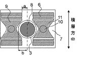
図1に示すように、安全弁3は正極及び負極の一対の通電部品4間に位置する蓋板の中心線上に配置されており、蓋板の中心線から安全弁の最外径までの距離はbである。前記蓋板7の中心線から前記通電部品4における前記安全弁側の端部までの距離はaである。通常、安全弁と通電部品4が重なるのを防ぐため、前記蓋板7の中心線から前記通電部品4における前記安全弁側の端部までの距離aが、蓋板の中心線から安全弁の最外径までの距離bより大きくとるが、大容量化に対応して通電部品4を大きくできないため、大容量化に伴う放電電流の増加が困難となる。また、安全弁の動作時における開口部から蓋板面への投影領域8と通電部品から蓋板面への投影領域9が重なっていると、異常時に発生したガスが安全弁から排出される際、通電部品4に妨げられたり、金属集電板の溶融片が通電部品4のところで詰まったりする恐れがある。本実施例では、蓋板中心線から通電部品4における安全弁側の端部までの距離aは、蓋板中心線から安全弁の最外径までの距離bよりも小さくなっている。すなわち、通電部品4の端部を安全弁最外径よりも蓋板中央寄りに配置している。また、タブ6と通電部品4の端子基体部11と接続位置は、安全弁の動作時における開口部から蓋板面への投影領域8よりも蓋外縁部側に位置している。このことにより、タブ6との接合面積を広くとることが可能となり、大容量化に伴う通電抵抗の増大を抑制できた。しかも、安全弁の動作時における開口部から蓋板面への投影領域8と通電部品から蓋板面への投影領域9が重なっていないため、異常時に発生したガスが安全弁から排出される際、通電部品4に妨げられたり、金属集電板の溶融片が通電部品4のところで詰まったりすることがなくなった。
なお、蓋板7には通電部品4が通る穴が空いており、シール部品(図示せず)、絶縁部品(図示せず)や締結部品(図示せず)を介して通電部品4が蓋板7に固定される。もちろん、蓋板7と通電部品4との接続方法はこれに限らず、蓋板7と通電部品4をモールド成形等により一体に成形してもよい。なお、通電部品4は蓋板7とは電気的に絶縁されている。
As shown in FIG. 1, the
The
安全弁3は円形状であって、円形状の中心が蓋板7の対角線交差中心に1つ配置されている。電池内部で気化したガスにより電池内圧が上昇し、安全弁3の耐圧よりも大きくなると、安全弁の開口部が溝パターンに沿って開裂し、電池内部のガスが安全弁を通して電池缶外に開放される。安全弁は、積層体内における金属集電体の積層方向と直角方向に配置されており、発生したガスは、金属集電体の層間を通り、スムースに安全弁より排出される。また、安全弁の円形状の中心が蓋板7の対角線交差中心にあることで、安全弁が蓋の端部近くにあるよりも、電池が傾いた場合でも、缶内にガスの滞留が生じにくい。安全弁の形状は、正円形以外でも楕円形や角丸長方形や卵形形状など円弧を含む形状であってもよい。安全弁3は、円形のステンレス鋼薄板にエッチングによって溝パターンが形成されており、所定の圧力で溝の部分から破断し、溝パターンに沿って開口する方式となっている。開裂する圧力は、安全弁の外径と溝パターン径の関係によって調整される。
The
安全弁3の溝形成方式としては、エッチング以外にも、加圧によって溝を形成してもよいし、レーザーや切削加工により溝を形成してもよいし、溝形成方式を特定するものではない。また、安全弁3はレーザー溶接により蓋板7に接合した。安全弁を蓋板に形成する方式としては、本実施例に限らず、例えば、蓋板7に直接、安全弁3を切削や加圧により機械的に形成する方式でも良いし、安全弁の形成方式を特定するものではない。また、安全弁3の材質もステンレス鋼以外にもアルミニウム、ニッケル等やふっ素系、ポリエチレン、ポリプロピレン等の樹脂でも良く、水分を通さず、蓋板材と同じ材質や接合しやすい材質から選んで用いることができる。
As a groove forming method of the
図1において、安全弁3は、蓋板7の対角線中心に配置されている。安全弁3の動作時には、この溝パターン外径が開口径となる。正極及び負極の通電部品4は、蓋板7中央を対称軸として左右対称に配置されている。このことにより、金属集電板から通電部品に流れる電流の分布が均等になる利点がある。安全弁の動作時における開口部から蓋板面への投影領域8と、通電部品から蓋板面への投影領域9は重なっていない。すなわち、安全弁の動作時における開口部から蓋板面への投影領域8と通電部品から蓋板面への投影領域9とは、一部または全部が重ならないことにより、電池缶内部の主に積層体で発生したガスが、積層体から蓋板の安全弁の開口部までの空間内において、通電部品に妨げられずに通ることができるため、ガス放出が確実に行われて安全性が確保でき、安全性を高めた電池構造を提供できる。さらに本実施例1の電池を作製し、過充電試験を行い、内圧、温度、電池電圧、電流を測定した。安全弁が動作するまで連続充電を行った結果、安全弁は所定の圧力で開放され、ガスが放出された。安全弁が開放された後は、金属集電板が安全弁や通電部品に詰まったり、突沸のような急激な圧力変動が見られたりすることはなく、時間とともに内圧は低減し、安全性が高い電池であることが確認できた。
In FIG. 1, the
<実施例2>
図3は本発明の実施例による電池を蓋板方向から見た平面投影図である。実施例1よりも電池容量を1.25倍に大容量化した250Ah積層型リチウムイオン二次電池を作製した。正極及び負極活物質層の改良により、容量密度を向上させた。蓋板7寸法は、実施例1と同じである。通電部品4において、端子基体部11は、蓋板に対して垂直に起立している端子本体10の周辺が凹んだ構造となっている。安全弁の動作時における開口部から蓋板面への投影領域8と、通電部品から蓋板面への投影領域9は重なっていない。蓋板7の幅は実施例1と同じであり、蓋に配置されている正極と負極の通電部品4間の距離は実施例1と同じであるが、安全弁3の直径、及び、開口部直径を大きくした。安全弁3は、蓋板7の対角線交差中心に位置している。
<Example 2>
FIG. 3 is a plan view of the battery according to the embodiment of the present invention as viewed from the direction of the cover plate. A 250 Ah stacked lithium ion secondary battery having a capacity 1.25 times larger than that of Example 1 was produced. The capacity density was improved by improving the positive electrode and negative electrode active material layers. The dimensions of the
本実施例では、蓋板中心線から通電部品4における安全弁側の端部までの距離aは、蓋板中心線から安全弁の最外径までの距離bよりも小さくなっている。すなわち、通電部品4の端部を安全弁最外径よりも蓋板中央寄りに配置している。このことにより、タブ6との接合面積を広くとることが可能となり、大容量化に伴う通電抵抗の増大を抑制できた。
In this embodiment, the distance a from the cover plate center line to the end of the energized component 4 on the safety valve side is smaller than the distance b from the cover plate center line to the outermost diameter of the safety valve. That is, the end of the energization component 4 is arranged closer to the center of the lid plate than the outermost diameter of the safety valve. This makes it possible to increase the bonding area with the
積層体から出ている電気接続部位、すなわちタブ6は、安全弁の最外径よりも蓋外縁部側で通電部品4の端子基体部11と接合されている。また、タブ6は枚数が多いため、正極・負極ごとに、4箇所に分けて接合されている。
The electrical connection portion, i.e., the
このように、タブ6と通電部品4の端子基体部11との接続位置を蓋外縁部側に配置したことにより、安全弁の直径を大きくとることができた。すなわち安全弁が円形状で、その円形状の中心が蓋板の対角線交差中心に位置し、積層体を構成している金属集電体の長手方向の端部に形成されたタブ6と、通電部品4の端子基体部11とを接続する位置が、安全弁の最外径よりも蓋外縁部側に配置されていることにより、蓋板面への各投影領域8,9が重ならないため、円形状の安全弁を広く形成することが可能になり、大容量化した電池においても安全性を確保した電池構造を提供できる。
Thus, by arranging the connection position between the
安全弁は図4のようにS字の溝5を形成した。溝5のパターンは、安全弁の中心を通る直線と、安全弁の円周外縁に沿った円弧から成り、連続的に溝5が形成されている。これより、安全弁3の動作時には、溝パターンの破断により、開口部が形成される。すなわち、この開口部の面積が、安全弁の動作時における開口部から蓋板面への投影領域8である。開口時に安全弁の破片が飛び散らないように、溝パターンは閉じた形状を有していない。すなわち、開口したあとでも、溝以外の安全弁を形成している面は電池の一部として蓋板7の一部として留まっている。
The safety valve has an S-shaped
溝はエッチングにより形成した。安全弁に用いた箔はステンレス鋼であり、実施例1と同じ材質である。実施例1と同様に、ステンレス鋼以外でも、水分を通さず、蓋板材同じ材質や接合しやすい材質から選んで用いることができる。溝形状は、エネルギーを瞬時に放出する必要から、安全弁の円周外縁に近い方が開裂したときに大口径となるようにした方がよい。しかしながら、溝円弧が外周部に近いほど、安全弁を蓋板に付ける際の熱歪等の影響を受け安く、開裂圧にバラツキが生じやすい。 The groove was formed by etching. The foil used for the safety valve is stainless steel and is the same material as in Example 1. Similarly to Example 1, other than stainless steel, it is possible to select and use the same material as the lid plate material or a material that can be easily joined without passing moisture. Since the groove shape needs to release energy instantaneously, it is better to have a large diameter when the one near the outer circumferential edge of the safety valve is cleaved. However, the closer the groove arc is to the outer peripheral portion, the less susceptible to thermal distortion when the safety valve is attached to the lid plate, the more likely the variation in cleavage pressure occurs.
本発明の溝パターンは、中心部を通るため、開裂溝パターンのうち、この中心付近で最初に亀裂が入り、溝部を亀裂が伝播し、連続して形成されている外周部の円弧部分まで伝播して弁が開く。このため、開裂圧にバラツキが少なく、且つ、開口径を大きくとることができた。溝パターンは図4以外にも、例えば、図5、図6、図7のように、安全弁の中心を通り、外周部に沿って円弧を形成するパターンであればよい。 Since the groove pattern of the present invention passes through the center portion, the crack is first cracked in the vicinity of the center of the cleavage groove pattern, and the crack propagates through the groove portion and propagates to the arc portion of the outer peripheral portion formed continuously. Then the valve opens. For this reason, there was little variation in the cleavage pressure, and the opening diameter could be increased. In addition to FIG. 4, the groove pattern may be a pattern that forms an arc along the outer peripheral portion through the center of the safety valve as shown in FIGS. 5, 6, and 7, for example.
図5は、安全弁中心を起点とした渦巻パターンであり、動作時は、中心付近の溝部から亀裂が入り、最外周溝部まで溝に沿って亀裂が伝播し、安全弁が開口する。 FIG. 5 shows a spiral pattern starting from the center of the safety valve. During operation, a crack enters from the groove near the center, the crack propagates along the groove to the outermost peripheral groove, and the safety valve opens.
図6は、寺の地図記号に類似した溝パターンであり、動作時は、中央の溝が交差している付近から開裂し、4つの部分に分かれて開口される。 FIG. 6 shows a groove pattern similar to a map symbol of a temple. During operation, the groove pattern is cleaved from the vicinity where the central groove intersects and is opened in four parts.
図7は、アルファベットのeの字に類似したパターンであり、中心を通る直線部の溝から開裂し、連続してつながっている外周部の円弧状の溝へ亀裂が伝播して、安全弁が開口する。 Fig. 7 shows a pattern similar to the letter e of the alphabet, which is cleaved from a straight groove passing through the center, and a crack propagates to a continuous arc-shaped groove on the outer periphery, opening the safety valve. To do.
図5、図6及び図7とも、安全弁3の動作時の開口径は本実施例と実質的に同じになる。特に、図4、図5、図7の各溝パターンは交差を伴わない一筆書き状に連続してつながっており、溝パターンにおける亀裂伝播の向きが一義的に決まるため、確実に開裂することができる。ここで、溝パターンは、S字形状、渦巻き形状、寺の地図記号に類似した形状、アルファベットのeの字に類似した形状に特定されることなく、円弧を有する形状であれば、効果が得られる。
5, 6, and 7, the opening diameter during operation of the
このように、安全弁が溝パターンを形成した円形金属箔から成り、溝パターンは安全弁の中心を通り、且つ外周部に沿った円弧からなり、溝パターンは一筆書き状に連続してつながっていることにより、安全弁の開口圧のばらつきが小さくなり、所定の圧力で開口することができるため、安全性が確保でき、安全性を高めた電池構造を提供できる。 In this way, the safety valve is made of a circular metal foil having a groove pattern, the groove pattern is made of an arc along the outer periphery of the safety valve, and the groove pattern is continuously connected in a single stroke. Therefore, variation in the opening pressure of the safety valve is reduced, and the opening can be performed at a predetermined pressure. Therefore, safety can be ensured, and a battery structure with improved safety can be provided.
図4、図5、図6、図7の安全弁と比較のために図8のような中心を通らない溝パターンを作製し、開裂試験を実施したところ、図4から図7の溝パターンの開裂圧のばらつきは、図8の溝パターンの開裂圧のばらつきに比べて、小さいことがわかった。 For comparison with the safety valve of FIGS. 4, 5, 6, and 7, a groove pattern that does not pass through the center as shown in FIG. 8 was prepared, and a cleavage test was performed. It was found that the variation in pressure was smaller than the variation in cleavage pressure of the groove pattern in FIG.
本実施例2の電池を作製して、過充電試験を行い、内圧、温度、電池電圧、電流を測定した。安全弁が動作するまで連続充電を行った結果、安全弁は所定の圧力で開放され、ガスが放出された。安全弁が開放された後は、金属集電板が安全弁や通電部品に詰まったり、突沸のような急激な圧力変動が見られたりすることはなく、時間とともに内圧は低減し、安全性が高い電池であることが確認できた。 The battery of Example 2 was manufactured, an overcharge test was performed, and the internal pressure, temperature, battery voltage, and current were measured. As a result of continuous charging until the safety valve operated, the safety valve was opened at a predetermined pressure, and gas was released. After the safety valve is opened, the metal current collector plate will not clog the safety valve or current-carrying parts, or sudden pressure fluctuations such as bumping will not be seen. It was confirmed that.
本実施例2のように、活物質材料の特性向上により、積層体において同じ体積当たりの容量が増加した場合でも、電池缶寸法を大きくすることなく、安全弁の大面積化が図れ、安全性を確保できたる。また、寸法が同じ金属集電板を用いて、積層枚数を変えることで大容量化した場合でも、電池缶の幅を大きくすることなく、安全弁の大面積化が図れ、安全性を確保できる。 As in Example 2, even when the capacity per volume of the laminate increases due to the improvement of the characteristics of the active material, the area of the safety valve can be increased without increasing the size of the battery can, and safety can be improved. It can be secured. Further, even when the capacity is increased by changing the number of stacked layers using metal current collector plates having the same dimensions, the area of the safety valve can be increased without increasing the width of the battery can, thereby ensuring safety.
1…積層体、2…電池缶、3…安全弁、4…通電部品、5…溝、6…タブ、7…蓋板、8…安全弁の動作時における開口部から蓋板面への投影領域、9…通電部品から蓋板面への投影領域、10…端子本体、11…端子基体部、a…正極及び負極の1対の端子間の蓋板中心線からの通電部品端部までの距離、b…正極及び負極の1対の端子間の蓋板中心線から安全弁最外径までの距離。
DESCRIPTION OF
Claims (8)
外部出力用の正極及び負極端子である通電部品が端子本体と端子本体の基部に形成された端子基体部を備えて構成され、端子基体部において積層体との電気接続が行われ、
積層体を内包する電池缶の蓋板に安全弁が形成され、
前記通電部品の端子本体と前記安全弁とは同一の蓋板に配置され、且つ、前記安全弁は正極及び負極の一対の通電部品間に位置する蓋板の中心線の少なくとも一部を覆うように配置されており、前記蓋板の中心線から前記通電部品の前記安全弁側の端部までの距離(a)が、前記蓋板の中心線から前記安全弁の最外径までの距離(b)以下であり、且つ、前記安全弁の動作時におけるその開口部から前記蓋板面への投影領域と前記通電部品から前記蓋板面への投影領域とが重ならない構成とすることを特徴とする二次電池。 A laminate in which a metal current collector having a negative electrode active material layer formed on the surface, a separator for holding an electrolyte, and another metal current collector having a positive electrode active material layer formed on the surface are alternately arranged in a strip shape. A battery having
A current-carrying component that is a positive electrode and a negative electrode terminal for external output includes a terminal body and a terminal base part formed at the base of the terminal body, and electrical connection with the laminate is performed in the terminal base part,
A safety valve is formed on the cover plate of the battery can containing the laminate,
A terminal body and the safety valve of the through conductive components are arranged on the same cover plate, and, as the safety valve to cover at least a portion of the centerline of the cover plate positioned between the positive electrode and a pair of energizing parts of the negative electrode The distance (a) from the center line of the lid plate to the end of the energized part on the safety valve side is not more than the distance (b) from the center line of the lid plate to the outermost diameter of the safety valve. And the projection area from the opening to the lid plate surface during operation of the safety valve does not overlap the projection region from the energized component to the lid plate surface. battery.
Priority Applications (5)
| Application Number | Priority Date | Filing Date | Title |
|---|---|---|---|
| JP2010058224A JP5703573B2 (en) | 2010-03-15 | 2010-03-15 | Secondary battery |
| KR1020110019972A KR101821675B1 (en) | 2010-03-15 | 2011-03-07 | Secondary battery |
| CN201110053581.1A CN102195024B (en) | 2010-03-15 | 2011-03-07 | Secondary cell |
| EP11157535.3A EP2372809B1 (en) | 2010-03-15 | 2011-03-09 | Secondary battery |
| US13/044,887 US9065098B2 (en) | 2010-03-15 | 2011-03-10 | Secondary battery |
Applications Claiming Priority (1)
| Application Number | Priority Date | Filing Date | Title |
|---|---|---|---|
| JP2010058224A JP5703573B2 (en) | 2010-03-15 | 2010-03-15 | Secondary battery |
Publications (2)
| Publication Number | Publication Date |
|---|---|
| JP2011192550A JP2011192550A (en) | 2011-09-29 |
| JP5703573B2 true JP5703573B2 (en) | 2015-04-22 |
Family
ID=44279755
Family Applications (1)
| Application Number | Title | Priority Date | Filing Date |
|---|---|---|---|
| JP2010058224A Expired - Fee Related JP5703573B2 (en) | 2010-03-15 | 2010-03-15 | Secondary battery |
Country Status (5)
| Country | Link |
|---|---|
| US (1) | US9065098B2 (en) |
| EP (1) | EP2372809B1 (en) |
| JP (1) | JP5703573B2 (en) |
| KR (1) | KR101821675B1 (en) |
| CN (1) | CN102195024B (en) |
Families Citing this family (22)
| Publication number | Priority date | Publication date | Assignee | Title |
|---|---|---|---|---|
| US9099729B2 (en) * | 2011-10-06 | 2015-08-04 | Toyota Jidosha Kabushiki Kaisha | Assembled battery and manufacturing method of assembled battery |
| CN103999259A (en) * | 2011-11-01 | 2014-08-20 | 日立麦克赛尔株式会社 | Sealed cell |
| JP2013182784A (en) * | 2012-03-01 | 2013-09-12 | Hitachi Maxell Ltd | Sealed battery |
| JP2013182785A (en) * | 2012-03-01 | 2013-09-12 | Hitachi Maxell Ltd | Sealed battery |
| JP2013239274A (en) * | 2012-05-14 | 2013-11-28 | Hitachi Maxell Ltd | Sealed battery |
| JP6016478B2 (en) * | 2012-06-28 | 2016-10-26 | ニチコン株式会社 | Pressure valve for electrolytic capacitor and electrolytic capacitor using the same |
| JP6359454B2 (en) * | 2012-09-28 | 2018-07-18 | 三洋電機株式会社 | Nonaqueous electrolyte secondary battery |
| JP2014107147A (en) * | 2012-11-28 | 2014-06-09 | Toyota Industries Corp | Electricity storage device |
| JP6122947B2 (en) * | 2013-04-16 | 2017-04-26 | 株式会社ソーデナガノ | Battery case |
| JP6044465B2 (en) * | 2013-06-25 | 2016-12-14 | 株式会社豊田自動織機 | Power storage device |
| JP6044482B2 (en) * | 2013-07-30 | 2016-12-14 | 株式会社豊田自動織機 | Method for manufacturing power storage device |
| JP6015595B2 (en) * | 2013-08-22 | 2016-10-26 | 株式会社豊田自動織機 | Power storage device |
| CN104091902B (en) * | 2014-07-15 | 2016-07-06 | 惠州威健锂能电子有限公司 | A kind of disposable lithium ion battery of heat shrinkable plastic film shell and manufacture method thereof |
| WO2016009586A1 (en) * | 2014-07-15 | 2016-01-21 | 三洋電機株式会社 | Electricity storage device |
| JP6394894B2 (en) * | 2014-12-19 | 2018-09-26 | 株式会社豊田自動織機 | Power storage device |
| WO2018230148A1 (en) * | 2017-06-15 | 2018-12-20 | 株式会社村田製作所 | Secondary battery, battery pack, electric vehicle, power storage system, electric tool, and electronic apparatus |
| JP6852629B2 (en) * | 2017-09-12 | 2021-03-31 | トヨタ自動車株式会社 | Power storage device |
| JP2019075214A (en) * | 2017-10-12 | 2019-05-16 | 株式会社Gsユアサ | Power storage element and manufacturing method of power storage element |
| JP7029924B2 (en) * | 2017-10-17 | 2022-03-04 | 株式会社Gsユアサ | Power storage element and power storage module |
| CN114424375A (en) * | 2019-12-16 | 2022-04-29 | 株式会社村田制作所 | Secondary battery, method for manufacturing secondary battery, electronic device, and electric power tool |
| CN112670596B (en) * | 2020-12-16 | 2022-06-07 | 曙鹏科技(深圳)有限公司 | Battery cell, battery cell winding method and battery |
| CN113745746B (en) * | 2021-11-03 | 2022-04-29 | 深圳小木科技有限公司 | New energy environment-friendly battery with cover plate easy to assemble |
Family Cites Families (20)
| Publication number | Priority date | Publication date | Assignee | Title |
|---|---|---|---|---|
| US2401448A (en) * | 1943-09-16 | 1946-06-04 | Electric Storage Battery Co | Filling and venting structure for storage batteries |
| JP3573295B2 (en) | 1994-04-28 | 2004-10-06 | 日本電池株式会社 | Square sealed battery |
| JP4355865B2 (en) | 1998-11-10 | 2009-11-04 | 株式会社ジーエス・ユアサコーポレーション | battery |
| JP2000182591A (en) * | 1998-12-15 | 2000-06-30 | Japan Storage Battery Co Ltd | Battery |
| JP2000251949A (en) * | 1999-02-24 | 2000-09-14 | Sanyo Electric Co Ltd | Sealed storage battery |
| JP4233671B2 (en) | 1999-03-01 | 2009-03-04 | パナソニック株式会社 | Non-aqueous electrolyte secondary battery |
| JP4486223B2 (en) * | 2000-06-16 | 2010-06-23 | 三菱重工業株式会社 | Method for forming safety valve of non-aqueous electrolyte secondary battery and non-aqueous electrolyte secondary battery |
| JP3840896B2 (en) * | 2000-12-01 | 2006-11-01 | 新神戸電機株式会社 | Square non-aqueous electrolyte battery |
| JP4955865B2 (en) * | 2001-06-05 | 2012-06-20 | ミヤマツール株式会社 | Sealing plate for sealed battery and method for manufacturing the same |
| JP4191411B2 (en) * | 2002-01-11 | 2008-12-03 | 三菱重工業株式会社 | Secondary battery container and manufacturing method thereof |
| JP2005190708A (en) * | 2003-12-24 | 2005-07-14 | Sanyo Electric Co Ltd | Square battery |
| JP4797335B2 (en) * | 2004-04-28 | 2011-10-19 | 株式会社Gsユアサ | battery |
| KR100599748B1 (en) * | 2004-06-23 | 2006-07-12 | 삼성에스디아이 주식회사 | Secondary battery and cap assembly and safety valve using the same and method for mounting safety valve |
| JP2006216435A (en) * | 2005-02-04 | 2006-08-17 | Nec Tokin Tochigi Ltd | Sealed battery |
| JP2006324178A (en) * | 2005-05-20 | 2006-11-30 | Kyushu Electric Power Co Inc | Secondary battery |
| JP2007157678A (en) * | 2005-05-23 | 2007-06-21 | Matsushita Electric Ind Co Ltd | Safety mechanism for laminate battery |
| JP4996857B2 (en) * | 2006-01-24 | 2012-08-08 | トヨタ自動車株式会社 | battery |
| JP5146110B2 (en) * | 2008-05-29 | 2013-02-20 | トヨタ自動車株式会社 | Battery, vehicle and battery-equipped equipment |
| JP2010040328A (en) * | 2008-08-05 | 2010-02-18 | Sanyo Electric Co Ltd | Sealed battery |
| JP2010097769A (en) * | 2008-10-15 | 2010-04-30 | Mitsubishi Heavy Ind Ltd | Battery terminal, secondary battery, method for manufacturing battery terminal, and method for manufacturing secondary battery |
-
2010
- 2010-03-15 JP JP2010058224A patent/JP5703573B2/en not_active Expired - Fee Related
-
2011
- 2011-03-07 CN CN201110053581.1A patent/CN102195024B/en not_active Expired - Fee Related
- 2011-03-07 KR KR1020110019972A patent/KR101821675B1/en active IP Right Grant
- 2011-03-09 EP EP11157535.3A patent/EP2372809B1/en not_active Not-in-force
- 2011-03-10 US US13/044,887 patent/US9065098B2/en not_active Expired - Fee Related
Also Published As
| Publication number | Publication date |
|---|---|
| EP2372809A1 (en) | 2011-10-05 |
| KR20110103859A (en) | 2011-09-21 |
| EP2372809B1 (en) | 2013-08-28 |
| US20110311847A1 (en) | 2011-12-22 |
| CN102195024B (en) | 2015-09-30 |
| KR101821675B1 (en) | 2018-01-24 |
| JP2011192550A (en) | 2011-09-29 |
| CN102195024A (en) | 2011-09-21 |
| US9065098B2 (en) | 2015-06-23 |
Similar Documents
| Publication | Publication Date | Title |
|---|---|---|
| JP5703573B2 (en) | Secondary battery | |
| EP2254176B1 (en) | Rechargeable battery | |
| JP6158474B2 (en) | Secondary battery | |
| US8883332B2 (en) | Rechargeable secondary battery | |
| KR101201746B1 (en) | Rechargeable battery | |
| JP6003655B2 (en) | Secondary battery | |
| EP2648246B1 (en) | Secondary battery | |
| KR102253021B1 (en) | Rechargeable battery having fuse and battery module | |
| JP5886059B2 (en) | Rectangular secondary battery and manufacturing method thereof | |
| US20040126650A1 (en) | Electrode assembly for lithium ion cell and lithium cell using the same | |
| KR101912004B1 (en) | Lithium secondary battery with improved safety by using bimetal tab | |
| KR20120063264A (en) | Cap assembly and secondary battery using the same | |
| US9356309B2 (en) | Prismatic battery | |
| JP2008103302A (en) | Battery module | |
| EP3770988A1 (en) | Secondary battery | |
| KR20120062254A (en) | Electrode assembly and secondary battery using the same | |
| KR20080016047A (en) | Rechargeable battery | |
| KR102487890B1 (en) | Secondary battery | |
| JP5547110B2 (en) | Non-aqueous electrolyte secondary battery | |
| KR102468048B1 (en) | Cylindrical Battery Cell Having Low Resistance | |
| KR20220120331A (en) | Secondary battery and battery module including the same | |
| JP6051855B2 (en) | battery | |
| JP2006079932A (en) | Lithium ion secondary battery | |
| JP6044818B2 (en) | Exterior container, storage element | |
| JP2019032991A (en) | Sealed battery |
Legal Events
| Date | Code | Title | Description |
|---|---|---|---|
| A621 | Written request for application examination |
Free format text: JAPANESE INTERMEDIATE CODE: A621 Effective date: 20121219 |
|
| A977 | Report on retrieval |
Free format text: JAPANESE INTERMEDIATE CODE: A971007 Effective date: 20140129 |
|
| A131 | Notification of reasons for refusal |
Free format text: JAPANESE INTERMEDIATE CODE: A131 Effective date: 20140325 |
|
| A521 | Request for written amendment filed |
Free format text: JAPANESE INTERMEDIATE CODE: A523 Effective date: 20140526 |
|
| A131 | Notification of reasons for refusal |
Free format text: JAPANESE INTERMEDIATE CODE: A131 Effective date: 20141104 |
|
| A521 | Request for written amendment filed |
Free format text: JAPANESE INTERMEDIATE CODE: A523 Effective date: 20141225 |
|
| TRDD | Decision of grant or rejection written | ||
| A01 | Written decision to grant a patent or to grant a registration (utility model) |
Free format text: JAPANESE INTERMEDIATE CODE: A01 Effective date: 20150127 |
|
| A61 | First payment of annual fees (during grant procedure) |
Free format text: JAPANESE INTERMEDIATE CODE: A61 Effective date: 20150209 |
|
| R150 | Certificate of patent or registration of utility model |
Ref document number: 5703573 Country of ref document: JP Free format text: JAPANESE INTERMEDIATE CODE: R150 |
|
| LAPS | Cancellation because of no payment of annual fees |