JP5698397B2 - Jig for pattern block machining in sector mold - Google Patents
Jig for pattern block machining in sector mold Download PDFInfo
- Publication number
- JP5698397B2 JP5698397B2 JP2014050235A JP2014050235A JP5698397B2 JP 5698397 B2 JP5698397 B2 JP 5698397B2 JP 2014050235 A JP2014050235 A JP 2014050235A JP 2014050235 A JP2014050235 A JP 2014050235A JP 5698397 B2 JP5698397 B2 JP 5698397B2
- Authority
- JP
- Japan
- Prior art keywords
- pattern block
- sector
- jig
- groove
- positioning pin
- Prior art date
- Legal status (The legal status is an assumption and is not a legal conclusion. Google has not performed a legal analysis and makes no representation as to the accuracy of the status listed.)
- Expired - Fee Related
Links
- 238000003754 machining Methods 0.000 title description 10
- 238000012545 processing Methods 0.000 claims description 15
- 238000003780 insertion Methods 0.000 claims description 5
- 230000037431 insertion Effects 0.000 claims description 5
- 210000000988 bone and bone Anatomy 0.000 description 37
- 238000003466 welding Methods 0.000 description 22
- 238000000034 method Methods 0.000 description 13
- 238000004519 manufacturing process Methods 0.000 description 5
- 238000004073 vulcanization Methods 0.000 description 3
- XEEYBQQBJWHFJM-UHFFFAOYSA-N Iron Chemical compound [Fe] XEEYBQQBJWHFJM-UHFFFAOYSA-N 0.000 description 2
- 239000011324 bead Substances 0.000 description 2
- 238000005266 casting Methods 0.000 description 2
- 238000012937 correction Methods 0.000 description 2
- 238000005520 cutting process Methods 0.000 description 2
- 230000007547 defect Effects 0.000 description 2
- 238000005304 joining Methods 0.000 description 2
- 239000000463 material Substances 0.000 description 2
- 229910000831 Steel Inorganic materials 0.000 description 1
- 238000005452 bending Methods 0.000 description 1
- 238000010276 construction Methods 0.000 description 1
- 238000013461 design Methods 0.000 description 1
- 230000000694 effects Effects 0.000 description 1
- 238000007730 finishing process Methods 0.000 description 1
- 238000002513 implantation Methods 0.000 description 1
- 238000009434 installation Methods 0.000 description 1
- 229910052742 iron Inorganic materials 0.000 description 1
- 238000000465 moulding Methods 0.000 description 1
- 230000002093 peripheral effect Effects 0.000 description 1
- 239000010959 steel Substances 0.000 description 1
- 230000001502 supplementing effect Effects 0.000 description 1
Images


Landscapes
- Moulds For Moulding Plastics Or The Like (AREA)
- Heating, Cooling, Or Curing Plastics Or The Like In General (AREA)
Description
本発明はセクター金型におけるパタンブロックの加工用冶具に関する。 The present invention relates to a tool for processing a pattern block in a sector mold.
タイヤ加硫用金型は、一般に空気入りタイヤのサイドウォール部を成形する一対のサイドプレートと、ビード部を成形する一対のビードリングと、トレッド部と両ショルダー部を一体的に成形するセクター金型とを備えている。セクター金型は、複数のセクターに分割されて未加硫空気入りタイヤのトレッド部の周囲に環状に配置される。 Tire vulcanizing molds generally include a pair of side plates for forming a sidewall portion of a pneumatic tire, a pair of bead rings for forming a bead portion, and a sector die for integrally forming a tread portion and both shoulder portions. With a mold. The sector mold is divided into a plurality of sectors and arranged in a ring around the tread portion of the unvulcanized pneumatic tire.
セクターのトレッド成形面には、例えば、タイヤ周方向に延びる主溝を成形するための主溝形成骨と、ショルダー部においてタイヤ幅方向に延びるラグ溝を成形するためのラグ溝形成骨と、ショルダー部及びセンター部においてタイヤ周方向に対して傾斜するスラント溝を成形するためのスラント溝形成骨などが形成されている。セクターにおけるこれらの各溝形成骨のパタンは、セクターとは別に彫刻加工で形成され、彫刻加工されたパタンブロックとして各セクターに取り付けられる。 The tread molding surface of the sector includes, for example, a main groove forming bone for forming a main groove extending in the tire circumferential direction, a lug groove forming bone for forming a lug groove extending in the tire width direction at the shoulder portion, and a shoulder Slant groove forming bones and the like for forming slant grooves that are inclined with respect to the tire circumferential direction in the center part and the center part are formed. The pattern of each groove-forming bone in the sector is formed by engraving separately from the sector, and is attached to each sector as an engraved pattern block.
ところで、パタンブロックのパタンは、従来ラグ溝形成用のパタンが主流であったが、近年はタイヤ性能要求から細溝形成骨を備える傾向が増大している。
従来、パタンブロックの彫刻加工は、パタン彫刻用冶具(以下単に冶具という)に対して、全周を溶接してずれのないように固定した上で行っている。そのため細溝形成骨を溶接で固定する場合には、細溝形成骨の固定強度を確保できるだけの溶接代を取って、全周を溶接固定しなければならない。
By the way, as a pattern of the pattern block, a pattern for forming a lug groove has been mainly used in the past. However, in recent years, there is an increasing tendency to provide a narrow groove forming bone because of tire performance requirements.
Conventionally, pattern block engraving is performed on a pattern engraving jig (hereinafter simply referred to as a jig) by welding the entire circumference and fixing it so as not to be displaced. Therefore, when fixing the narrow groove forming bone by welding, it is necessary to weld and fix the entire circumference by taking a welding allowance sufficient to secure the fixing strength of the narrow groove forming bone.
ところが、パタンブロックを冶具に対して全周にわたって溶接固定すると、冶具との脱着にかなりの工数が必要となると云う問題がある。また、それだけではなく、溶接固定による熱でパタンブロックに歪みが起きやすく、とくに、タイヤの細溝形成骨を成形する場合は、加工中に発生するビビリや溶接歪みにより加工精度が低下し易い。また、パタンブロックの加工中にビビリや溶接歪みが発生すると、加工後に、それをセクターへ取り付ける時に、その反り返りや曲がりを修正する必要が出てくる。 However, when the pattern block is welded and fixed to the jig over the entire circumference, there is a problem that a considerable number of man-hours are required for detachment from the jig. In addition, the pattern block is apt to be distorted by heat due to welding and fixing, and particularly, when forming a narrow groove forming bone of a tire, processing accuracy is likely to decrease due to chatter and welding distortion generated during processing. Further, if chatter or welding distortion occurs during the processing of the pattern block, it is necessary to correct the warping or bending when attaching it to the sector after processing.
また、従来パタンブロックをセクターに取り付ける際には、ボルトによって位置を仮止めし、予めセクターに付しておいた罫書き線に合わせて微修正を行いながら取り付けの位置決めを行っている。しかし、罫書きによる周方向位置決め精度はそれ程よくはない。 In addition, when a conventional pattern block is attached to a sector, the position is temporarily fixed by a bolt, and the attachment is positioned while performing fine correction in accordance with a ruled line previously attached to the sector. However, the circumferential positioning accuracy by scribing is not so good.
また、パタンブロックの裏胴面は、セクターの踏面(セクター面)形状に合わせて機械加工した後、セクターへ取り付けている。近年は、パタンブロックの裏胴面の機械加工精度が向上し、そのままセクター面に取り付けできる精度が得られるが、折角、高い精度で機械加工を行っても、その後のパタンブロックの彫刻加工中に発生する歪みや反りなどにより、その機械加工精度を維持するのは難しい。そのため、パタンブロックの裏胴面とセクター面との摺り合わせ作業を行いながら取り付けを行っている。そのため、パタンブロックのセクターへの取り付けは煩雑で人手を要するものとなっている。また、その摺り合わせ作業は、全面を摺り合わせるのは難しいため、裏胴面の一部にヌスミを設け、セクターの踏面との摺り合わせ範囲(面積)を少なくして行っている。しかし、それでもその煩雑さは十分解消されない。 The back body surface of the pattern block is machined according to the shape of the tread (sector surface) of the sector and then attached to the sector. In recent years, the machining accuracy of the back block surface of the pattern block has been improved, and the accuracy that can be directly attached to the sector surface can be obtained. However, even if machining is performed with high accuracy, the pattern block can still be engraved later. It is difficult to maintain the machining accuracy due to the generated distortion and warpage. For this reason, the attachment is performed while the back surface of the pattern block and the sector surface are rubbed together. Therefore, the installation of the pattern block to the sector is complicated and requires human labor. In addition, since it is difficult to rub the entire surface, the rubbing operation is performed by providing a part of the back trunk surface to reduce the rubbing range (area) with the tread surface of the sector. However, the complexity is still not solved.
これに対し、例えば、特許文献1には、パタンブロックをホルダーに溶接する場合に歪みが生じないようにするために、パタンブロックを鉄板で製造する方法が記載されている。
この方法では、鉄板を溶断したのち荒加工し、ホルダー(セクター)背面にヌスミを形成してパタンブロックを形成し、それをホルダーに溶接している。この方法では、溶接による歪みは、鋳物でパタンブロックを形成する場合に比べて生じ難いが、そもそも鋳物でパタンブロック形成するのは対象外である。
On the other hand, for example, Patent Document 1 describes a method of manufacturing a pattern block with an iron plate in order to prevent distortion when the pattern block is welded to a holder.
In this method, the steel plate is melted and then roughed, and a pattern block is formed by forming a nose on the back of the holder (sector), which is welded to the holder. In this method, distortion due to welding is less likely to occur than in the case where the pattern block is formed by casting, but in the first place, the pattern block is not formed by casting.
特許文献2には、リブとラグで形成した連結骨部(パタンブロック)のリブを、取付ボールトによって金型本体(セクター)に取り付けることが記載されている。しかし、この取付方法では、パタンブロックの底面はセクター上に載っているだけであるため、位置精度の問題があることに加え、パタンブロックの剛性を強化することはできないという問題がある。そこで強度確保のためには、パタンブロックの外形に沿って溶接固定せざるを得ず、工数増は避けられない。 Patent Document 2 describes that a rib of a connecting bone portion (pattern block) formed by a rib and a lug is attached to a mold body (sector) by an attachment vault. However, this mounting method has a problem that the rigidity of the pattern block cannot be enhanced in addition to the problem of positional accuracy because the bottom surface of the pattern block is only placed on the sector. Therefore, in order to ensure the strength, it is necessary to weld and fix the outer shape of the pattern block, and an increase in man-hours is inevitable.
特許文献3には、各ピース(パタンブロック)は、それぞれその両端に形成した固定部をブロック(セクター)の嵌合溝に嵌合させることにより、各ピースをブロックに嵌着し、従来のように締結手段を用いて固定することがないようにしている。
しかし、この方法ではブロックの嵌合溝を形成する加工が複雑である。
In Patent Document 3, each piece (pattern block) is fitted to each block by fitting fixed portions formed at both ends thereof into fitting grooves of the block (sector). The fastening means is not used for fixing.
However, in this method, the process of forming the block fitting groove is complicated.
本発明は、従来の加硫金型製造における前記の問題に鑑みてなされたものであって、その目的は、パタンブロックをセクターに対して簡易かつ位置精度よく取り付けでき、しかもその強度を向上させることである。 The present invention has been made in view of the above-mentioned problems in conventional vulcanization mold manufacturing, and its object is to easily and accurately attach a pattern block to a sector and to improve its strength. That is.
本願の発明は、埋め込み溝及び位置決めピン用穴を設けたセクターと、裏胴面に、前記埋め込み溝及び位置決めピン用穴に対応して、それぞれ埋め込み溝用凸部及び位置決めピンを設けたパタンブロックとを備え、前記パタンブロックを前記セクターに取り付けて構成したセクター金型における前記パタンブロックの加工用冶具であって、前記パタンブロックの埋め込み溝用凸部及び位置決めピンに対応した埋め込み溝及び位置決めピン用穴を備えた、パタンブロックの加工用冶具である。 The invention of the present application includes a sector provided with a buried groove and a positioning pin hole, and a pattern block provided with a buried groove convex portion and a positioning pin on the back body surface corresponding to the buried groove and the positioning pin hole, respectively. The pattern block processing jig in a sector mold configured by attaching the pattern block to the sector, the embedding groove and the positioning pin corresponding to the embedding groove convex portion and the positioning pin of the pattern block It is a jig for processing a pattern block with a hole.
本発明によれば、パタンブロックをセクターに対して簡易かつ位置精度よく取り付けでき、しかもその強度を向上させることができる。 According to the present invention, the pattern block can be easily attached to the sector with high positional accuracy, and its strength can be improved.
本発明のセクター金型の実施形態について説明する。
図1Aはセクター10を示す斜視図であり、図1Bは図1Aの矩形で囲った部分Sの細部構造を示す拡大図である。
本実施形態のセクター金型は、従来と同様に、タイヤトレッド部を構成する複数のセクター10とセクター10の骨となるパタンブロック20を別々に製造し、セクター10に対して、彫刻加工したパタンブロック20を取り付けて形成される。
An embodiment of a sector mold according to the present invention will be described.
FIG. 1A is a perspective view showing a
In the sector mold according to the present embodiment, a plurality of
ただ、本実施形態のセクター10の表面には、従来のセクターとは異なり、図示のようにパタンブロック20の外形の一部の形状(ここでは細溝形成骨)に合わせてくりぬいた埋め込み溝12と、位置決めピン用穴14と、パタンブロック20をセクター10の外形部から固定するためのボルト挿通穴16が設けられている。なお、図中破線Tはパタンブロック20の取付位置を示している。
図1Bは、図1Aの矩形で囲った部分Sの細部構造を示す拡大図であり、セクター10に設けた埋め込み溝12を拡大して示している。
However, unlike the conventional sector, on the surface of the
FIG. 1B is an enlarged view showing a detailed structure of a portion S surrounded by a rectangle in FIG. 1A, and shows an embedded
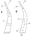
図2Aは、図1のセクター10に取り付けるパタンブロック20の正面図、図2Bはその裏胴面20aを示す裏面図である。
パタンブロック20は、比較的幅広のタイヤのラグ溝形成骨21とそれに続きそれよりも幅が狭い細溝形成骨22とから成っている。また、ラグ溝形成骨21にはタイヤ周方向の細溝を形成するための周方向細溝形成骨18(図5)が一体に形成される。
パタンブロック20の裏胴面20aは、従来と同様にセクター10の踏面(セクター面)形状に合わせて機械加工されており、かつ図1に示すセクター10の前記埋め込み溝12と位置決めピン用穴14に対応して、埋め込み溝用凸部22aと複数の位置決めピン24が形成されている。即ち、埋め込み溝12と埋め込み溝用凸部22a、位置決めピン用穴14と、それに嵌合する位置決めピン24とが互いに嵌合する大きさと位置に形成されている。
2A is a front view of the
The
The
ここで、前記埋め込み溝12はセクター面10a(図1)を、また前記埋め込み溝用凸部22aはパタンブロック20の裏胴面20aをそれぞれ切削装置などの任意の手段で形成する。また、位置決めピン24は別途作成したピンをパタンブロック20に植設或いは溶接などにより取り付ける。また、パタンブロック20には、パタンブロック20をセクター10に固定するためのネジ溝つきのボルト穴26が設けられている。
Here, the embedded
次に、以上で説明した構造のパタンブロック20の彫刻加工について説明する。
図3は、パタンブロック20を彫刻加工するためのパタン彫刻加工冶具(以下、単に冶具という)を示す斜視図である。
図示のように冶具30の表面30aは、セクター10のセクター面10a(図1)と同じ三次元形状に機械加工され、その表面30aにはセクター10と同じ形状の埋め込み溝32及び同じ配置の位置決めピン用穴34及び固定用のボルト挿通穴36が設けられている。
Next, engraving of the
FIG. 3 is a perspective view showing a pattern engraving jig (hereinafter simply referred to as a jig) for engraving the
As shown, the
パタンブロック20の彫刻加工時には、冶具30の埋め込み溝32及び位置決めピン用穴34へ、パタンブロック20の裏胴面20aの埋め込み溝用凸部22a及び複数の位置決めピン24を挿入する。その後、冶具30の裏側からボルト挿通穴36を介して固定ボルト15(図4)を挿通し、パタンブロック20の前記ボルト穴26にねじ込み締め付ける。
本実施形態においては、パタンブロック20の裏胴面20a及び冶具30の表面はいずれもセクター10のセクター面形状に合わせて機械加工されているため、冶具30とパタンブロック20は密接して一体に固定され、被加工体であるパタンブロック20の剛性が増し、加工工具より加えられる切削抵抗や熱によるパタンブロック20のビビリ、反り返りといった加工不良を抑制して良好な加工仕上がり面を得ることができる。また、パタンブロック20の裏胴面20aの機械加工精度も維持することができる。
When engraving the
In the present embodiment, since the
図4は、図2に示す彫刻加工が施されたパタンブロック20を、セクター10のセクター面10aに取り付けた状態を示すパタンブロック20の長手方向に沿った断面図である。
加工済みのパタンブロック20をセクター10に取り付けるには、セクター10に設けられた埋め込み溝12に、パタンブロック20の前記埋め込み溝用凸部22aをガイドにして、図4に示すように、セクター10の位置決めピン用穴14にパタンブロック20の位置決めピン24を嵌め込んで組み合わせ、セクター10の外周面から、前記ボルト穴16を介してパタンブロック20のボルト穴26に固定ボルト15を差し込んで、締め付けて両者を一体に固定する。
4 is a cross-sectional view along the longitudinal direction of the
In order to attach the processed
なお、前記埋め込み溝12は、要求される骨の強度、固定強度によって図示のように剛性の弱い細溝形成骨22だけに設けてもよいが、パタンブロック20の外形の一部或いは全周にわたって設けてもよい。この点は、当然のことながら冶具30の埋め込み溝32についても同様である。
The embedded
図5は、固定ボルト15でセクター面10aに固定した状態のパタンブロック20を示す斜視図である。この図示例では、既に4本のパタンブロックの埋め込み固定を終了し、1本のパタンブロックは未取付状態となっている。未取付状態の埋め込み溝12は、ここではパタンブロック20全体を埋め込む溝として形成されている。このようにパタンブロック20全体をセクター面10aに埋め込む場合には、パタンブロック20の強度は一層強化される。
FIG. 5 is a perspective view showing the
図中18は周方向細溝形成骨を表す。このように周方向細溝形成骨18を設けた場合、この周方向細溝形成骨18部分でパタンブロック20を分割し、周方向細溝形成骨18の部分を溶接固定する。これにより周方向細溝形成骨18の強度を補えるほか、溶接後の摺り合わせ作業を容易に行うことができる。
即ち、パタンブロック20のラグ溝形成骨21と周方向細溝形成骨18とは、タイヤにおける応力緩和を目的にその接合部にR形状が施されている。したがって、その接合部でパタンブロック20を分割すると、各セクター10を接合する際に、このR形状を肉盛り溶接で形成する必要があり、場合によっては更に機械加工が必要になる。
これに対し、本実施形態のように、周方向細溝形成骨18部分で分割すると、溶接固定が必要な溝形成骨の接合部は周方向細溝形成骨18部分のみであるため、単に周方向細溝形成骨18同士を溶接固定すれば足り、したがって、溶接後の摺り合わせ作業が容易に行える。
In the figure, 18 represents a circumferential narrow groove forming bone. When the circumferential narrow
That is, the lug
On the other hand, if the circumferential narrow
図5に示すように、パタンブロック20を固定ボルト15でセクター10に固定した後、セクター10とパタンブロック20の接合線に沿ってベアの発生を防止するために設けた空気溝(ベントグルーブ)を人手によりタガネで打ってかしめ、或いは溶接で隙間を埋め、仕上げ加工を行ってセクター10が完成する。また、このセクター10を円環状に配置してセクター金型が構成される。
As shown in FIG. 5, after the
なお、埋め込み溝のない従来構造では、既に述べたように、パタンブロック20の取り付けにおいて、前記パタンブロック20をセクター10に仮止めし、予めパタンブロック20の取付目標位置に入れておいた罫書き線をガイドとして微修正を行いながら固定している。しかし、このような固定法では、パタンブロック20はセクター面10aに乗っているだけであり、パタンブロック20はセクター面10aにより補強されることがなく剛性が低い。そのためタイヤ製造時(加硫時)の脱型に対する強度確保のため、パタンブロック20をその外形に沿ってセクター面10aに溶接固定せざるを得なかった。
In the conventional structure having no embedded groove, as already described, when the
これに対し、本実施形態によれば、パタンブロック20を埋め込み溝12に嵌め込むだけで、正しい位置決めが可能であると共にその剛性を増すことができる。とくに、パタンブロック20の冶具30への固定は、固定ボルト15により行うことができ、溶接で固定した場合に比して、パタンブロック20の固定後の仕上げ加工が簡易である。
セクター10へのパタンブロック20の固定に際しては、既に述べたように
パタンブロック20のセクター面10aの形状に合わせて機械加工された裏胴面20aは、パタン彫刻加工中に歪みや反りが発生することなく機械加工精度が維持されるため、従来のようにパタンブロック20の裏胴面20aの摺り合わせ加工を行う必要がない。
On the other hand, according to the present embodiment, just by inserting the
When the
なお、パタンブロック20の構成材料は、セクター10と同じ材料でもよいが、セクター10の構成材料よりも熱膨張の大きな材料を選定すれば、加硫中の熱膨張差を利用して、つまり熱膨張による嵌め合いによって、セクター10側の埋め込み溝12及びパタンブロック20の裏胴面20aの埋め込み溝用凸部22aの隙間が小さくなり、パタンブロック20の固定強度を増すことができる。
The material of the
以上、本実施形態のセクター金型、セクター金型の製造方法及びセクター金型製造用冶具について説明したが、本実施形態によれば以下に示すような効果が得られる。
(1)セクター10へブロックを取り付ける際、セクター10の埋め込み溝12及び位置決めピン24と、パタンブロック20の裏胴面20aの埋め込み溝用凸部22a及び位置決めピン24を単に嵌合させることで、従来のパタンブロックに比べ位置決め精度が向上し、同時に固定強度を向上させることができる。
また、溶接作業を最小限に抑えることができるため、溶接による歪みや反り返りを抑制することができ、パタンブロック20のセクター10への固定作業を容易に行うことができる。
The sector mold, the sector mold manufacturing method, and the sector mold manufacturing jig of the present embodiment have been described above, but according to the present embodiment, the following effects can be obtained.
(1) When the block is attached to the
Moreover, since welding work can be suppressed to the minimum, distortion and warping due to welding can be suppressed, and the work of fixing the
(2)セクター10へパタンブロック20を取り付ける際に、埋め込み溝12及び埋め込み溝用凸部22aを取付ガイドとすることで、位置決めが容易である。
(3)パタンブロック20の裏胴面20aとセクター10のセクター面10aとの摺り合わせを実施することなく、両者を取り付けることができる。また、セクター10とパタンブロック20の接合部には隙間がなく良好な金型形状及び製品面を得ることができる。
(2) When the
(3) Both can be attached without carrying out the sliding of the
(4)パタンラグ溝形成骨に周方向細溝形成骨18がつながっている場合、周方向細溝形成骨部でパタンブロック20を分割し、細溝形成骨部を溶接固定することで周方向細溝形成骨18の強度を補えるほか、溶接後の摺り合わせ作業が容易に行える。
(5)従来のようにパタン彫刻時に冶具へ溶接固定するのをやめて、背面(裏胴面)からのボルト固定のみに変更すると共に、位置決めピン24を設けたことにより、パタンブロック20の冶具30への固定性、位置決め精度を向上させることができる。
(4) When the circumferential fine
(5) Stopping welding and fixing to the jig during pattern engraving as in the prior art, and changing to only fixing bolts from the back (back body surface), and providing the
(6)冶具30側に埋め込み溝32、パタンブロック20の裏胴面20aにそれに対応した埋め込み溝用凸部22aを設けたため、パタンブロック20の固定性、位置決め精度が向上したほか、ビビリや溶接歪みによる反り返りがなく加工不良が抑制できる。なお、冶具30に細溝形成骨22の埋め込み溝32を設けるだけでも良好な加工仕上がり面を得ることができる。
(7)セクター10とパタンブロック20を別工程で製作するため、工程のクリティカルパス(直列な工程)を解消でき、工程設計の自由度が増し、工期を短縮することができる。
(6) The embedding
(7) Since the
10・・・セクター、10a・・・セクター面、12・・・埋め込み溝、14・・・位置決めピン用穴、15・・・固定ボルト、16・・・ボルト挿通穴、18・・・周方向細溝形成骨、20・・・パタンブロック、20a・・・裏胴面、21・・・ラグ溝形成骨、22・・・細溝形成骨、22a・・・埋め込み溝用凸部、24・・・位置決めピン、26・・・ボルト穴、30・・・冶具、32・・・埋め込み溝、34・・・位置決めピン用穴、36・・・ボルト挿通穴。
DESCRIPTION OF
Claims (3)
前記パタンブロックの埋め込み溝用凸部及び前記位置決めピンに対応した埋め込み溝及び位置決めピン用穴を備えた、パタンブロックの加工用冶具。 A sector provided with a buried groove and a positioning pin hole, and a pattern block provided with a buried groove convex portion and a positioning pin corresponding to the buried groove and the positioning pin hole on the back body surface, respectively, A jig for processing the pattern block in a sector mold configured by attaching a pattern block to the sector,
A pattern block processing jig, comprising a buried groove convex portion of the pattern block and a buried groove and a positioning pin hole corresponding to the positioning pin.
前記固定ボルトが挿通するボルト挿通穴を有するパタンブロックの加工用冶具。 In the pattern block processing jig according to claim 1, which has a bolt hole with which a fixing bolt is locked.
A pattern block processing jig having a bolt insertion hole through which the fixing bolt is inserted.
前記加工用冶具の表面は、前記セクターのセクター面と同じ三次元形状に機械加工されている、パタンブロックの加工用冶具。 In the pattern block processing jig according to claim 1 or 2,
The processing jig for a pattern block, wherein the surface of the processing jig is machined into the same three-dimensional shape as the sector surface of the sector.
Priority Applications (1)
| Application Number | Priority Date | Filing Date | Title |
|---|---|---|---|
| JP2014050235A JP5698397B2 (en) | 2014-03-13 | 2014-03-13 | Jig for pattern block machining in sector mold |
Applications Claiming Priority (1)
| Application Number | Priority Date | Filing Date | Title |
|---|---|---|---|
| JP2014050235A JP5698397B2 (en) | 2014-03-13 | 2014-03-13 | Jig for pattern block machining in sector mold |
Related Parent Applications (1)
| Application Number | Title | Priority Date | Filing Date |
|---|---|---|---|
| JP2013011381A Division JP5534483B1 (en) | 2013-01-24 | 2013-01-24 | Sector mold and manufacturing method |
Publications (2)
| Publication Number | Publication Date |
|---|---|
| JP2014141097A JP2014141097A (en) | 2014-08-07 |
| JP5698397B2 true JP5698397B2 (en) | 2015-04-08 |
Family
ID=51422833
Family Applications (1)
| Application Number | Title | Priority Date | Filing Date |
|---|---|---|---|
| JP2014050235A Expired - Fee Related JP5698397B2 (en) | 2014-03-13 | 2014-03-13 | Jig for pattern block machining in sector mold |
Country Status (1)
| Country | Link |
|---|---|
| JP (1) | JP5698397B2 (en) |
Families Citing this family (2)
| Publication number | Priority date | Publication date | Assignee | Title |
|---|---|---|---|---|
| KR20170015463A (en) | 2014-07-09 | 2017-02-08 | 히다치 오토모티브 시스템즈 가부시키가이샤 | Rotation angle detection device and power steering device |
| JP2019093672A (en) * | 2017-11-27 | 2019-06-20 | 株式会社ブリヂストン | Method of manufacturing mold for tire |
Family Cites Families (2)
| Publication number | Priority date | Publication date | Assignee | Title |
|---|---|---|---|---|
| FR2939712B1 (en) * | 2008-12-17 | 2011-01-14 | Michelin Soc Tech | MOLD TRIM COMPRISING A SACRIFICIAL LINK ELEMENT |
| FR2940166B1 (en) * | 2008-12-24 | 2011-02-11 | Michelin Soc Tech | METHOD FOR MANUFACTURING A TRIM MEMBER AND A SUPPORT MEMBER FOR A PNEUMATIC MOLD |
-
2014
- 2014-03-13 JP JP2014050235A patent/JP5698397B2/en not_active Expired - Fee Related
Also Published As
| Publication number | Publication date |
|---|---|
| JP2014141097A (en) | 2014-08-07 |
Similar Documents
| Publication | Publication Date | Title |
|---|---|---|
| EP2113357B1 (en) | Mold for tire | |
| JP6407820B2 (en) | Lining assembly including skin for tire vulcanization mold | |
| JP5534483B1 (en) | Sector mold and manufacturing method | |
| CN105793024B (en) | Method of cutting a section of a tire mould and providing a semi-finished element for moulding a section of a mould of a tire | |
| JP5698397B2 (en) | Jig for pattern block machining in sector mold | |
| US7377761B2 (en) | Tire vulcanizing mold | |
| EP3499210B1 (en) | Hybrid material airflow impression molds | |
| JP3182945U (en) | Ring mold for tire molding | |
| JP4690382B2 (en) | Manufacturing method of tire mold | |
| JP6280446B2 (en) | Tire mold and tire vulcanizer | |
| US20090260773A1 (en) | Die casting mold and method of manufacturing and casting the same | |
| KR101576645B1 (en) | a method of manufacturing a hot-stamping mold and a hot-stamping mold manufacturing the same method | |
| JP2018187864A (en) | Method for manufacturing tire mold | |
| JP2007062270A (en) | Mold for vulcanizing tire and manufacturing method of it | |
| CN109927213A (en) | Tread mould and its restorative procedure | |
| JP4926656B2 (en) | Mold for tire | |
| JP7468222B2 (en) | mold | |
| JP2007144997A (en) | Manufacturing method of tire mold | |
| EP3939763B1 (en) | Method for manufacturing tire forming mold | |
| JP2007015152A (en) | Manufacturing method of piece assembling type tire mold | |
| US20190054664A1 (en) | Method for producing mold for rubber article, mold for rubber article, method for producing mold member, and mold member | |
| JP2019093672A (en) | Method of manufacturing mold for tire | |
| JP2018027668A (en) | Mold for rubber crawler, and manufacturing method of rubber crawler using the same | |
| JP2018108706A (en) | Cleaning tool for mold | |
| JP2012162063A (en) | Method of producing mold for vulcanizing tire, and the mold for valcanizing tire |
Legal Events
| Date | Code | Title | Description |
|---|---|---|---|
| A977 | Report on retrieval |
Free format text: JAPANESE INTERMEDIATE CODE: A971007 Effective date: 20150120 |
|
| TRDD | Decision of grant or rejection written | ||
| A01 | Written decision to grant a patent or to grant a registration (utility model) |
Free format text: JAPANESE INTERMEDIATE CODE: A01 Effective date: 20150127 |
|
| A61 | First payment of annual fees (during grant procedure) |
Free format text: JAPANESE INTERMEDIATE CODE: A61 Effective date: 20150212 |
|
| R150 | Certificate of patent or registration of utility model |
Ref document number: 5698397 Country of ref document: JP Free format text: JAPANESE INTERMEDIATE CODE: R150 |
|
| R250 | Receipt of annual fees |
Free format text: JAPANESE INTERMEDIATE CODE: R250 |
|
| R250 | Receipt of annual fees |
Free format text: JAPANESE INTERMEDIATE CODE: R250 |
|
| R250 | Receipt of annual fees |
Free format text: JAPANESE INTERMEDIATE CODE: R250 |
|
| R250 | Receipt of annual fees |
Free format text: JAPANESE INTERMEDIATE CODE: R250 |
|
| LAPS | Cancellation because of no payment of annual fees |