JP5695038B2 - Coupling device - Google Patents
Coupling device Download PDFInfo
- Publication number
- JP5695038B2 JP5695038B2 JP2012516862A JP2012516862A JP5695038B2 JP 5695038 B2 JP5695038 B2 JP 5695038B2 JP 2012516862 A JP2012516862 A JP 2012516862A JP 2012516862 A JP2012516862 A JP 2012516862A JP 5695038 B2 JP5695038 B2 JP 5695038B2
- Authority
- JP
- Japan
- Prior art keywords
- stapes
- attachment means
- opening
- clip
- protrusion
- Prior art date
- Legal status (The legal status is an assumption and is not a legal conclusion. Google has not performed a legal analysis and makes no representation as to the accuracy of the status listed.)
- Expired - Fee Related
Links
Images


Classifications
-
- A—HUMAN NECESSITIES
- A61—MEDICAL OR VETERINARY SCIENCE; HYGIENE
- A61F—FILTERS IMPLANTABLE INTO BLOOD VESSELS; PROSTHESES; DEVICES PROVIDING PATENCY TO, OR PREVENTING COLLAPSING OF, TUBULAR STRUCTURES OF THE BODY, e.g. STENTS; ORTHOPAEDIC, NURSING OR CONTRACEPTIVE DEVICES; FOMENTATION; TREATMENT OR PROTECTION OF EYES OR EARS; BANDAGES, DRESSINGS OR ABSORBENT PADS; FIRST-AID KITS
- A61F2/00—Filters implantable into blood vessels; Prostheses, i.e. artificial substitutes or replacements for parts of the body; Appliances for connecting them with the body; Devices providing patency to, or preventing collapsing of, tubular structures of the body, e.g. stents
- A61F2/50—Prostheses not implantable in the body
- A61F2/76—Means for assembling, fitting or testing prostheses, e.g. for measuring or balancing, e.g. alignment means
-
- A—HUMAN NECESSITIES
- A61—MEDICAL OR VETERINARY SCIENCE; HYGIENE
- A61F—FILTERS IMPLANTABLE INTO BLOOD VESSELS; PROSTHESES; DEVICES PROVIDING PATENCY TO, OR PREVENTING COLLAPSING OF, TUBULAR STRUCTURES OF THE BODY, e.g. STENTS; ORTHOPAEDIC, NURSING OR CONTRACEPTIVE DEVICES; FOMENTATION; TREATMENT OR PROTECTION OF EYES OR EARS; BANDAGES, DRESSINGS OR ABSORBENT PADS; FIRST-AID KITS
- A61F11/00—Methods or devices for treatment of the ears or hearing sense; Non-electric hearing aids; Methods or devices for enabling ear patients to achieve auditory perception through physiological senses other than hearing sense; Protective devices for the ears, carried on the body or in the hand
- A61F11/04—Methods or devices for enabling ear patients to achieve auditory perception through physiological senses other than hearing sense, e.g. through the touch sense
-
- A—HUMAN NECESSITIES
- A61—MEDICAL OR VETERINARY SCIENCE; HYGIENE
- A61F—FILTERS IMPLANTABLE INTO BLOOD VESSELS; PROSTHESES; DEVICES PROVIDING PATENCY TO, OR PREVENTING COLLAPSING OF, TUBULAR STRUCTURES OF THE BODY, e.g. STENTS; ORTHOPAEDIC, NURSING OR CONTRACEPTIVE DEVICES; FOMENTATION; TREATMENT OR PROTECTION OF EYES OR EARS; BANDAGES, DRESSINGS OR ABSORBENT PADS; FIRST-AID KITS
- A61F2/00—Filters implantable into blood vessels; Prostheses, i.e. artificial substitutes or replacements for parts of the body; Appliances for connecting them with the body; Devices providing patency to, or preventing collapsing of, tubular structures of the body, e.g. stents
- A61F2/02—Prostheses implantable into the body
- A61F2/18—Internal ear or nose parts, e.g. ear-drums
-
- H—ELECTRICITY
- H04—ELECTRIC COMMUNICATION TECHNIQUE
- H04R—LOUDSPEAKERS, MICROPHONES, GRAMOPHONE PICK-UPS OR LIKE ACOUSTIC ELECTROMECHANICAL TRANSDUCERS; DEAF-AID SETS; PUBLIC ADDRESS SYSTEMS
- H04R25/00—Deaf-aid sets, i.e. electro-acoustic or electro-mechanical hearing aids; Electric tinnitus maskers providing an auditory perception
- H04R25/60—Mounting or interconnection of hearing aid parts, e.g. inside tips, housings or to ossicles
- H04R25/604—Mounting or interconnection of hearing aid parts, e.g. inside tips, housings or to ossicles of acoustic or vibrational transducers
- H04R25/606—Mounting or interconnection of hearing aid parts, e.g. inside tips, housings or to ossicles of acoustic or vibrational transducers acting directly on the eardrum, the ossicles or the skull, e.g. mastoid, tooth, maxillary or mandibular bone, or mechanically stimulating the cochlea, e.g. at the oval window
-
- A—HUMAN NECESSITIES
- A61—MEDICAL OR VETERINARY SCIENCE; HYGIENE
- A61F—FILTERS IMPLANTABLE INTO BLOOD VESSELS; PROSTHESES; DEVICES PROVIDING PATENCY TO, OR PREVENTING COLLAPSING OF, TUBULAR STRUCTURES OF THE BODY, e.g. STENTS; ORTHOPAEDIC, NURSING OR CONTRACEPTIVE DEVICES; FOMENTATION; TREATMENT OR PROTECTION OF EYES OR EARS; BANDAGES, DRESSINGS OR ABSORBENT PADS; FIRST-AID KITS
- A61F2/00—Filters implantable into blood vessels; Prostheses, i.e. artificial substitutes or replacements for parts of the body; Appliances for connecting them with the body; Devices providing patency to, or preventing collapsing of, tubular structures of the body, e.g. stents
- A61F2/02—Prostheses implantable into the body
- A61F2/18—Internal ear or nose parts, e.g. ear-drums
- A61F2002/183—Ear parts
Description
本発明は結合装置に係り、特に、アブミ骨底に人工中耳を結合する結合装置に関する。 The present invention relates to a coupling device, and more particularly, to a coupling device for coupling an artificial middle ear to a stapes bottom.
「中耳」という言葉は、外耳道と蝸牛の間に位置する鼓室を意味する。 The term “middle ear” refers to the tympanic chamber located between the ear canal and the cochlea.
健康な耳において、外耳道と鼓室との境界に位置する鼓膜(tympanic membrane)又は鼓膜(ear drum)の振動は、耳小骨連鎖と呼ばれる一連の3つの関節で繋がった骨によって鼓室を介して蝸牛に伝導される。 In a healthy ear, the vibration of the tympanic membrane or ear drum, located at the boundary between the ear canal and the tympanic chamber, is transmitted to the cochlea through the tympanic chamber by a series of three joints called the ossicular chain. Conducted.
耳小骨連鎖は、3つの個々の小骨で構成される。すなわちツチ骨、キヌタ骨及びアブミ骨である。ツチ骨は、鼓膜とキヌタ骨との間に接続されている。キヌタ骨は、同様にツチ骨とアブミ骨との間に接続されている。アブミ骨は、卵円窓として知られ、蝸牛の開口部を覆う膜に接触して配置されるアブミ骨底部を備える。 The ossicular chain is composed of three individual ossicles. That is, the tibia bone, quinuta bone and stapes bone. The gill bone is connected between the tympanic membrane and the quinuta bone. Kinuta bone is similarly connected between the heel bone and the stapes. The stapes are known as the oval window and comprise the stapes bottom placed in contact with the membrane covering the cochlear opening.
鼓膜の振動は、このように、小骨によって卵円窓膜に伝えられ、蝸牛を満たした液体の圧力変動を引き起こす。これらの圧力変動は、正円窓膜が卵円窓膜と逆相で振動するように、正円窓として知られる開口部を覆う第2の膜の存在によって提供される。 The vibration of the tympanic membrane is thus transmitted to the oval window membrane by a small bone, causing a pressure fluctuation of the liquid filling the cochlea. These pressure fluctuations are provided by the presence of a second membrane covering the opening, known as the round window, so that the round window membrane vibrates in reverse phase with the oval window membrane.
「人工中耳」という言葉は、一般に、感音難聴又は伝音難聴の患者の聴力を改善するために患者の鼓室に埋め込むことができる装置を意味する。 The term “artificial middle ear” generally refers to a device that can be implanted in a patient's tympanic chamber to improve the hearing of a patient with sensorineural or conductive hearing loss.
感音難聴は、震動の刺激を神経作用に変換する能力を低下させる内耳の欠陥、及び/又は聴覚と関連する神経系の一部分の欠陥に起因する。 Sensorineural hearing loss results from defects in the inner ear that reduce the ability to convert vibrational stimuli into neural effects and / or defects in parts of the nervous system associated with hearing.
伝音難聴は、中耳の伝導性の要素、すなわち耳小骨連鎖の欠陥に起因し、中耳腔を介した振動エネルギーの効果的な伝導を妨げる。 Conductive hearing loss is due to a defect in the middle ear conductive element, ie the ossicular chain, which prevents the effective conduction of vibrational energy through the middle ear cavity.
どちらの場合も、患者の聴力は、マイクや他のセンサーからの外部信号に応える中耳内の1つ以上の要素を積極的に振動させるための聴覚アクチュエータを導入することにより、内耳への振動刺激を増幅することによって改善することができる。 In either case, the patient's hearing is reduced by vibration to the inner ear by introducing an auditory actuator to actively vibrate one or more elements in the middle ear that respond to external signals from microphones and other sensors. It can be improved by amplifying the stimulus.
伝音難聴の場合には、患者の聴力は、耳小骨連鎖の全部又は一部を、導伝ブリッジとして機能するプロテーゼによって交換又はバイパスをつけることにより改善することができる。 In the case of conductive hearing loss, the patient's hearing can be improved by replacing or bypassing all or part of the ossicular chain with a prosthesis that functions as a conductive bridge.
このようなデバイスは、総称して人工中耳と呼ばれる。インプラント自体が振動エネルギーを生成することなく、中耳を介して振動エネルギーを伝導するインプラントは、受動型インプラント(passive implants)と呼ばれる。インプラント自体が振動エネルギーを生成するインプラントは、能動型インプラント(active implants)と呼ばれる。受動型と能動型の両方の要素を含む人工中耳もある。 Such devices are collectively referred to as artificial middle ears. Implants that conduct vibrational energy through the middle ear without the implant itself generating vibrational energy are called passive implants. Implants in which the implant itself generates vibrational energy are called active implants. Some cochlear implants contain both passive and active elements.
中耳内の様々な要素の間に伸びている多くの異なる人工中耳が開発されている。 Many different artificial middle ears have been developed that extend between various elements within the middle ear.
しかし、人工中耳をアブミ骨底に結合することが特に望ましく、アブミ骨底は卵円窓膜に対して位置し、したがって蝸牛を満たす液体に直接振動を伝導する。 However, it is particularly desirable to couple the artificial middle ear to the stapes bottom, which lies against the oval membrane and thus conducts vibration directly to the liquid filling the cochlea.
国際公開第2008/139225号は能動型の人工中耳について開示しており、人工中耳によって生成された振動がアブミ骨底に伝導され、従って蝸牛に伝導されるように、人工中耳はキヌタ骨の長い突起からアブミ骨底に延びている。 WO 2008/139225 discloses an active cochlear implant, where the cochlear implant is kinuta so that vibrations generated by the cochlear implant are transmitted to the floor of the stapes and thus to the cochlea. It extends from the long process of the bone to the bottom of the stapes.
人工中耳は、バネクリップによって、キヌタ骨の長い突起の一端に結合されている。しかし、アブミ骨底の形状は一般に平坦であるため、アブミ骨底に人工中耳の他端を結合することは簡単ではない。国際公開第2008/139225号では、人工中耳はロッドを備え、トランスデューサの端部から延び、アブミ骨底を押圧し、摩擦によってアブミ骨底を所定の位置に保持する。これは一般的に効果的である一方で、アブミ骨底上の振動が効果的に伝導されない場所、又はアブミ骨底と全く接触しない場所にロッドがスリップするリスクが残っている。 The artificial middle ear is connected to one end of the long protrusion of the quinuta bone by a spring clip. However, since the shape of the stapes is generally flat, it is not easy to connect the other end of the artificial middle ear to the stapes. In WO 2008/139225, the artificial middle ear comprises a rod, extends from the end of the transducer, presses against the stapes and holds it in place by friction. While this is generally effective, there remains the risk that the rod will slip where vibrations on the floor of the stapes are not effectively conducted, or where there is no contact with the stapes.
接触部がスリップするリスクは、ネジや生体適合性接着剤を使用する等の機械的手段によりアブミ骨底にロッドを固定することによって避けることができる。しかし、これは複雑で時間のかかる手術を必要とし、もし人工中耳を除去する必要があるときに、その影響を簡単に翻えせない。 The risk of the contact portion slipping can be avoided by fixing the rod to the stapes bone by mechanical means such as using screws or biocompatible adhesive. However, this requires complex and time consuming surgery, and the effect cannot be easily reversed if the artificial middle ear needs to be removed.
これが前述の問題を克服するための本発明の目的である。 This is the purpose of the present invention to overcome the aforementioned problems.
本発明の一態様によれば、中耳に埋め込まれる埋め込み型装置が提供され、この装置はアブミ骨底に係合するための係合手段を備え、係合手段は、
アブミ骨底に位置するように構成された第1の結合部と、
第1の結合部に結合するための第2の結合部とを備え、
第1及び第2の結合部の一方は突起を備え、他の一方の結合部は、第1の結合部と第2の結合部との間の枢軸結合を提供するための、突起を受けるための開口部が突起に対応して形成される。
According to one aspect of the present invention, an implantable device is provided that is implanted in the middle ear, the device comprising engagement means for engaging the stapes bone, the engagement means comprising:
A first coupling configured to be located at the floor of the stapes,
A second coupling part for coupling to the first coupling part,
One of the first and second coupling portions includes a protrusion, and the other coupling portion receives the protrusion to provide a pivotal connection between the first coupling portion and the second coupling portion. The opening is formed corresponding to the protrusion.
この構成によれば、アブミ骨底上の第1の結合部の所定位置を通って、また第2の結合部分を有する第1の結合部の結合を介して埋め込み型装置は安全にアブミ骨底上に取り付けられる。更に、第1及び第2の結合部の間の枢軸結合は、第1の結合部に対する第2の結合部の角度は、装置の埋め込みを容易にするために調整することができることを意味する。 According to this configuration, the implantable device can be safely passed through a predetermined position of the first coupling portion on the floor of the stapes and via the coupling of the first coupling portion having the second coupling portion. Mounted on top. Furthermore, the pivot coupling between the first and second coupling means that the angle of the second coupling relative to the first coupling can be adjusted to facilitate implantation of the device.
好ましい実施形態では、突起は第2の結合部に形成され、突起に対応する開口部は第1の結合部上に形成されている。つまり、開口部は好ましくは、接触するアブミ骨底の一部に形成されている。しかし、第1の結合部に突起が形成された状態で、開口部は代わりに第2の結合部に形成されていてもよい。 In a preferred embodiment, the projection is formed in the second coupling portion, and the opening corresponding to the projection is formed on the first coupling portion. That is, the opening is preferably formed in a part of the stapes bone that contacts. However, the opening may be formed in the second coupling portion instead with the protrusion formed in the first coupling portion.
突起又は開口部は好ましくは第1の結合部の中央に形成される。 The protrusion or opening is preferably formed in the center of the first coupling part.
従って、第1の結合部がアブミ骨底の中央に取り付けられたときに、第2の結合部は、アブミ骨のアーチから略等距離に配置することができる。アブミ骨のアーチから略等距離に位置する第2の結合部によって、より効果的にアブミ骨底と卵円窓に振動は伝導される。 Accordingly, when the first coupling portion is attached to the center of the stapes, the second coupling portion can be disposed at a substantially equal distance from the arch of the stapes. Vibrations are more effectively conducted to the floor of the stapes and the oval window by the second joint located approximately equidistant from the arch of the stapes.
突起は好ましくは円形である。特に、突起は好ましくは略一定の曲率半径を有する。より好ましくは、突起は略半球状である。 The protrusion is preferably circular. In particular, the protrusion preferably has a substantially constant radius of curvature. More preferably, the protrusion is substantially hemispherical.
突起が形成されている部分は、突起に隣接する環状溝を備える。これは、第1の結合部に関連する第2の結合部の角度調整の範囲を増加させる。 The portion where the protrusion is formed includes an annular groove adjacent to the protrusion. This increases the range of angular adjustment of the second coupling part relative to the first coupling part.
開口部は好ましくは曲率半径が略一定である。より好ましくは、開口部は略半球状である。両方のケースでは、突起の曲率半径は、開口部の曲率半径よりも部分的に小さい。これにより、突起の表面を凹部の表面に対してスライドさせる。一方で突起は凹部によってしっかりと保持される。 The opening preferably has a substantially constant radius of curvature. More preferably, the opening is substantially hemispherical. In both cases, the radius of curvature of the protrusion is partially smaller than the radius of curvature of the opening. Accordingly, the surface of the protrusion is slid with respect to the surface of the recess. On the other hand, the protrusion is firmly held by the recess.
あるいは、開口部は略円筒形である。円筒形の開口部は、円形又は半球形状を有するような適切に形成された突起と協調することができ、第1の結合部に対する第2の結合部の回動自在な移動を可能にする。 Alternatively, the opening is substantially cylindrical. The cylindrical opening can be coordinated with a suitably shaped protrusion such as having a circular or hemispherical shape, allowing a pivotable movement of the second coupling part relative to the first coupling part.
第2の結合部は、例えばロッドのような伸長部であってもかまわない。このケースでは突起又は開口部は、好ましくは伸長部の端部に形成される。突起が伸長部に形成されている場合には、突起は単に円形の端部であってもかまわない。 The second coupling portion may be an elongated portion such as a rod. In this case, the protrusion or opening is preferably formed at the end of the extension. In the case where the protrusion is formed in the elongated portion, the protrusion may be simply a circular end portion.
第1の結合部は摩擦によってアブミ骨底の表面に係合するように構成されても構わない。このケースでは、第1の結合部は好ましくはアブミ骨底の露出面の比較的大きな割合で接触するように構成された表面を有する。例えば、少なくともアブミ骨底の露出面の30%、より好ましくは少なくともアブミ骨底の50%である。そのようなケースでは、アブミ骨底上の水分に起因する表面張力は、アブミ骨底上に第1の結合部を保持するのに役立つ可能性がある。 The first coupling portion may be configured to engage the surface of the stapes bone by friction. In this case, the first joint preferably has a surface configured to contact a relatively large proportion of the exposed surface of the stapes. For example, at least 30% of the exposed surface of the stapes, more preferably at least 50% of the stapes. In such a case, the surface tension due to moisture on the stapes bottom may help to hold the first joint on the stapes bottom.
プレートがチタン又は骨の成長を促進する他の生理活性物質で作られている場合、骨は、時間の経過とともに、その位置に保持するために成長してプレートになることがある。 If the plate is made of titanium or other bioactive substance that promotes bone growth, the bone may grow into a plate over time to hold it in place.
あるいは、またはそれに加えて、埋め込み型装置は、アブミ骨底に第1の結合部を取り付けるための取付手段を備えても構わない。第1の結合部は取付手段によって取り付けられる又は取り付け可能であり、又は取付手段に一体形成することができる。 Alternatively or in addition, the implantable device may comprise attachment means for attaching the first coupling to the stapes bone. The first coupling part can be attached or attachable by attachment means, or can be integrally formed with the attachment means.
取付手段は好ましくは結合部によって結合される第1及び第2の係合部を備え、各係合部は、アブミ骨のアーチにそれぞれ係合するように構成された係合面を備える。 The attachment means preferably comprises first and second engagement portions coupled by a coupling portion, each engagement portion comprising an engagement surface configured to engage respectively with the stapes arch.
取付手段は、このようにアブミ骨のアーチに係合部を係合させることによってアブミ骨に接続することができる。この方法でアブミ骨に接続した場合は、接続部はアブミ骨底に及び、したがって、第1の結合部をアブミ骨底に結合することができる。 The attachment means can be connected to the stapes by engaging the engaging portion with the arch of the stapes in this way. When connected to the stapes in this way, the connection extends to the stapes and thus the first coupling can be connected to the stapes.
第1の係合部の係合面は、好ましくは第2の係合部の係合面と反対方向に面する。従って、係合部は、しっかりとアーチをつかむために反対方向にアブミ骨のアーチを押しつける。 The engagement surface of the first engagement portion preferably faces in the opposite direction to the engagement surface of the second engagement portion. Thus, the engagement portion presses the stapes of the stapes in the opposite direction to firmly grasp the arch.
取付手段は、係合面が互いに対向するように構成されてもかまわない。この場合、取付手段はアブミ骨のアーチの外側対向面を押しつける。あるいは、取付手段は、係合面が互いに外側を向くように構成されてもかまわない。この場合、取付手段はアブミ骨のアーチの内側対向面を押しつける。 The attachment means may be configured such that the engagement surfaces face each other. In this case, the attachment means presses the outer facing surface of the stapes arch. Alternatively, the attachment means may be configured such that the engagement surfaces face each other. In this case, the attachment means presses the inner facing surface of the stapes arch.
係合部の係合面は、好ましくはアブミ骨底に接触するアブミ骨のアーチの間の距離と略等しい距離だけ離間される。したがって、取付手段は、アブミ骨底に隣接する領域ではアブミ骨に取り付けられるように構成されている。 The engaging surfaces of the engaging portions are preferably spaced apart by a distance approximately equal to the distance between the stapes of the stapes that contacts the stapes. Therefore, the attachment means is configured to be attached to the stapes in a region adjacent to the stapes bone.
好ましくは、係合部はそれぞれ湾曲部を備え、各係合面は好ましくは凹面である。 Preferably, each engaging part is provided with a curved part, and each engaging surface is preferably a concave surface.
取付手段は、好ましくはアブミ骨のアーチを貫通するか、アブミ骨のアーチの周りを通過する第1の構成と、アブミ骨のアーチに係合する第2の構成との間で変形可能なように、少なくとも部分的に弾力性を有する。 The attachment means is preferably deformable between a first configuration that passes through or passes around the stapes arch and a second configuration that engages the stapes arch. And at least partially elastic.
特に、取付手段の結合部は、好ましくは少なくとも1つの弾性部を備える。これは、係合部がアブミ骨の周りを通過したり、アーチをつかむために開放される前にアブミ骨のアーチの間に挿入されるように取付手段が弾性変形することを意味する。 In particular, the coupling part of the attachment means preferably comprises at least one elastic part. This means that the attachment means is elastically deformed so that the engaging portion is inserted between the stapes of the stapes before passing around the stapes or being released to grab the arch.
接続部は、接続部の中央部の両側に1つずつ配置される2つの弾性部を備えても構わない。これにより、取付手段の弾力性に影響を与えることなく、接続部の中央部が第1の結合部に取り付けられる。第1の結合部は、接続部に取り付けられるか、又は取り付け可能であるか、又は接続部に一体形成されていても構わない。 The connecting portion may include two elastic portions arranged one on each side of the central portion of the connecting portion. Thereby, the center part of a connection part is attached to a 1st coupling | bond part, without affecting the elasticity of an attachment means. The first coupling portion may be attached to or attachable to the connection portion, or may be integrally formed with the connection portion.
取付手段は好ましくは超弾性特性を有する。この点において、取付手段は、好ましくは、少なくとも部分的に超弾性材料で形成されている。取付手段を形成する材料は、好ましくはニチノールのようなニッケルチタン合金、又はいくつかの他の合金やポリマー又は超弾性特性を有する他の材料である。 The attachment means preferably has superelastic properties. In this respect, the attachment means is preferably at least partly made of a superelastic material. The material forming the attachment means is preferably a nickel titanium alloy such as Nitinol, or some other alloy or polymer or other material having superelastic properties.
更に、取付手段は、好ましくは、自然の又は元の構成と、係合部がアブミ骨のアーチをつかむ第2の構成との間の偏差が十分に大きいように構成され、係合部はアブミ骨のアーチをつかむために超弾性動作する。つまり、アブミ骨のアーチ上の係合部によって発揮される力は、変形の広い範囲にわたってほぼ一定となる。所定の大きさの取付手段は、患者の間におけるアブミ骨の大きさの大幅な変動に対応することができることを意味するため望ましい。 Further, the attachment means is preferably configured such that the deviation between the natural or original configuration and the second configuration in which the engaging portion grips the stapes of the stapes is sufficiently large, Super elastic action to grab the bone arch. That is, the force exerted by the engaging part on the arch of the stapes is substantially constant over a wide range of deformation. An attachment means of a predetermined size is desirable because it means that it can accommodate large variations in the size of the stapes between patients.
取付手段は、好ましくはクリップである。 The attachment means is preferably a clip.
好ましい実施形態では、第1及び第2の係合部は第1の平面に向かって延び、接続部は第1の平面に垂直な第2の平面にある係合部から延びている。接続部の中心点は、好ましくは第1及び第2の平面の交点と一致する。 In a preferred embodiment, the first and second engaging portions extend toward the first plane, and the connecting portion extends from the engaging portion in a second plane perpendicular to the first plane. The center point of the connecting portion preferably coincides with the intersection of the first and second planes.
接続部は好ましくは少なくとも1つの湾曲部を備え、より好ましくは取付手段の中心で共に接続される2つの湾曲部を備える。特に好ましい実施形態では、クリップの接続部は略M字型である。そのような構成により、取付手段は超弾性的にアブミ骨のアーチをつかむことができる。 The connecting part preferably comprises at least one curved part, more preferably two curved parts connected together at the center of the attachment means. In a particularly preferred embodiment, the clip connection is generally M-shaped. With such a configuration, the attachment means can grasp the stapes of the stapes in a super elastic manner.
接続部は、好ましくは、それぞれ係合部に接続されている一組の外側の脚部を備える。これらの脚は、好ましくは片持ち梁のように形成される。これらの脚部のそれぞれの長さは、好ましくは脚部の断面寸法より実質的に大きい。より好ましくは、10〜50倍大きい。 The connecting portion preferably comprises a set of outer legs each connected to the engaging portion. These legs are preferably formed like cantilevers. The length of each of these legs is preferably substantially greater than the cross-sectional dimension of the legs. More preferably, it is 10 to 50 times larger.
装置は、好ましくは第1の結合部の開口部又は突起が、取付手段の係合面から略等距離に配置されるように構成される。 The device is preferably configured such that the opening or protrusion of the first coupling part is arranged at approximately the same distance from the engagement surface of the attachment means.
したがって、突起/開口部、そして第2の結合部を、アブミ骨のアーチから略等距離に配置することができる。アブミ骨のアーチから略等距離に位置する第2の結合部によってアブミ骨底と卵円窓に振動がより効果的に伝動される。 Thus, the protrusion / opening and the second coupling portion can be positioned approximately equidistant from the stapes arch. Vibration is more effectively transmitted to the floor of the stapes and the oval window by the second coupling portion located at approximately the same distance from the arch of the stapes.
開口部又は突起(又はその中心点)は、望ましくは係合面間の中心点からオフセットされている。 The opening or protrusion (or its center point) is desirably offset from the center point between the engagement surfaces.
したがって、この装置がアブミ骨に取り付けられたときに、突起/開口部がアブミ骨のアーチの直下に配置されることはない。 Thus, when the device is attached to the stapes, no protrusions / openings are placed directly under the stapes arch.
突起/開口部がアブミ骨のアーチの直下に配置される場合、アブミ骨の上部は人工中耳の通過を阻害し、第2の結合部は、アブミ骨の上部を避けるために、垂線から離れて傾ける必要があることを意味する。これは振動の伝導の効率を低下させる。なぜなら、第2の結合部に垂直な力の成分が減少するためである。 When the process / opening is placed directly below the stapes of the stapes, the upper part of the stapes obstructs the passage of the artificial middle ear and the second joint is separated from the perpendicular to avoid the upper part of the stapes. Means you need to tilt. This reduces the efficiency of vibration conduction. This is because the force component perpendicular to the second coupling portion decreases.
実質的に第2の結合部に垂直な力の成分を最大にするために、また振動の伝動効率を向上するために、開口部/突起のオフセットにより、第1及び第2の結合部間の接触角は略90度になる。 In order to maximize the force component substantially perpendicular to the second joint and to improve the transmission efficiency of the vibration, the offset between the openings / protrusions causes the first and second joints to be The contact angle is approximately 90 degrees.
装置は好ましくは生体適合性材料で形成される。 The device is preferably formed of a biocompatible material.
本発明の第2の態様によると、アブミ骨底に埋め込み型装置を取り付けるための取付手段が設けられ、取付手段は、接続部で接続された第1及び第2の係合部を備え、そこにおいて各係合部は、アブミ骨のアーチのそれぞれに係合するように構成されている。 According to the second aspect of the present invention, there is provided attachment means for attaching the implantable device to the stapes bone, and the attachment means comprises first and second engagement parts connected by a connection part. Each engaging portion is configured to engage each of the stapes arches.
取付手段は、このように係合部をアブミ骨のアーチに係合させることによってアブミ骨に取り付けることができる。この方法でアブミ骨に取り付けた場合は、接続部はアブミ骨底に及び、したがって、埋め込み型装置をアブミ骨底に結合することができる。 The attachment means can be attached to the stapes by engaging the engaging portion with the arch of the stapes in this way. When attached to the stapes in this manner, the connection extends to the stapes and thus the implantable device can be coupled to the stapes.
第1の係合部の係合面は、好ましくは第2の係合部の係合面と反対方向に面している。したがって、係合部は、しっかりとアーチをつかむために反対方向にアブミ骨のアーチを押し付ける。 The engagement surface of the first engagement portion preferably faces in the opposite direction to the engagement surface of the second engagement portion. Thus, the engagement portion presses the stapes of the stapes in the opposite direction to firmly grasp the arch.
係合部は、係合面が互いに対向するように構成されていても構わない。このケースでは、取付手段はアブミ骨のアーチの外側対向面を押し付ける。 The engaging portion may be configured such that the engaging surfaces face each other. In this case, the attachment means presses against the outer facing surface of the stapes arch.
これは一般的に有効であるが、いくつかの構成では、取付手段がアブミ骨のアーチに乗り上がり、アブミ骨底との接触を失い、アーチのつかみが減少する可能性がある。これは、凹面が互いに外側に向くように構成されている取付手段を提供することにより回避することができる。このケースでは、取付手段はアブミ骨のアーチの内側対向面を押し付ける。 While this is generally effective, in some configurations, the attachment means can ride on the stapes of the stapes, lose contact with the stapes of the stapes and reduce arch grip. This can be avoided by providing attachment means that are configured such that the concave surfaces face each other. In this case, the attachment means presses against the inner facing surface of the stapes arch.
係合面は、好ましくはアブミ骨底に接触するアブミ骨のアーチの間の距離と略等しい距離だけ離間されている。このため、取付手段はアブミ骨底に隣接する領域ではアブミ骨に取り付けられるように構成される。 The engaging surfaces are preferably spaced apart by a distance approximately equal to the distance between the stapes of the stapes that contact the stapes. For this reason, the attachment means is configured to be attached to the stapes in a region adjacent to the stapes bone.
好ましくは、係合部はそれぞれ湾曲部を備え、係合面は好ましくは凹面である。 Preferably, the engaging portions each have a curved portion, and the engaging surface is preferably a concave surface.
取付手段は好ましくは、アブミ骨のアーチを貫通するか、アブミ骨のアーチの周りを通過する第1の構成と、アブミ骨のアーチに係合する第2の構成との間で変形可能なように、少なくとも部分的に弾力性を有する。 The attachment means is preferably deformable between a first configuration that passes through or passes around the stapes of the stapes and a second configuration that engages the stapes of the stapes. And at least partially elastic.
特に、取付手段の接続部は、好ましくは少なくとも1つの弾性部を備える。これにより、係合部がアーチをつかむために開放される前に、係合部がアブミ骨のアーチの周りを通過するか、アブミ骨のアーチの間に挿入することができるように、取付手段が弾性変形する。 In particular, the connecting part of the attachment means preferably comprises at least one elastic part. This enables the attachment means so that the engagement part can pass around or be inserted between the stapes arches before the engagement parts are opened to grab the arches. Is elastically deformed.
接続部は、接続部の中央部の両側に1つずつ配置される2つの弾性部を備える。これにより、取付手段の弾力性に影響を与えずに、更なる要素に接続部の中央部を取り付けることができる。 The connecting portion includes two elastic portions arranged one on each side of the central portion of the connecting portion. Thereby, the central part of a connection part can be attached to a further element, without affecting the elasticity of an attachment means.
取付手段は好ましくは超弾性特性を有する。この点において、取付手段は、好ましくは、少なくとも部分的に超弾性材料で形成されている。取付手段を形成する材料は、好ましくはニチノールのようなニッケルチタン合金、又はいくつかの他の合金やポリマー又は超弾性特性を有する他の材料である。 The attachment means preferably has superelastic properties. In this respect, the attachment means is preferably at least partly made of a superelastic material. The material forming the attachment means is preferably a nickel titanium alloy such as Nitinol, or some other alloy or polymer or other material having superelastic properties.
更に、取付手段は、好ましくは、自然の又は元の構成と、係合部がアブミ骨のアーチをつかむ第2の構成との間の偏差が十分に大きいように構成され、係合部はアブミ骨のアーチをつかむために超弾性動作する。つまり、アブミ骨のアーチ上の係合部によって発揮される力は、変形の広い範囲にわたってほぼ一定となる。所定の大きさの取付手段は、患者の間におけるアブミ骨の大きさの大幅な変動に対応することができることを意味するため望ましい。 Further, the attachment means is preferably configured such that the deviation between the natural or original configuration and the second configuration in which the engaging portion grips the stapes of the stapes is sufficiently large, Super elastic action to grab the bone arch. That is, the force exerted by the engaging part on the arch of the stapes is substantially constant over a wide range of deformation. An attachment means of a predetermined size is desirable because it means that it can accommodate large variations in the size of the stapes between patients.
取付手段は、好ましくはクリップである。 The attachment means is preferably a clip.
好ましい実施形態では、第1及び第2の係合部は第1の平面に向かって延び、接続部は第1の平面に垂直な第2の平面にある係合部から延びている。接続部の中心点は、好ましくは第1及び第2の平面の交点と一致する。 In a preferred embodiment, the first and second engaging portions extend toward the first plane, and the connecting portion extends from the engaging portion in a second plane perpendicular to the first plane. The center point of the connecting portion preferably coincides with the intersection of the first and second planes.
接続部は好ましくは少なくとも1つの湾曲部を備え、より好ましくは取付手段の中心で一緒に接続される2つの湾曲部を備える。特に好ましい実施形態では、クリップの接続部は略M字型である。そのような構成により、取付手段は超弾性的にアブミ骨のアーチをつかむことができる。 The connecting part preferably comprises at least one curved part, more preferably two curved parts connected together at the center of the attachment means. In a particularly preferred embodiment, the clip connection is generally M-shaped. With such a configuration, the attachment means can grasp the stapes of the stapes in a super elastic manner.
接続部は、好ましくは、それぞれ係合部に接続されている一組の外側の脚部を備える。これらの脚は、好ましくは片持ち梁のように形成される。これらの脚部のそれぞれの長さは、好ましくは脚部の断面寸法より実質的に大きい。より好ましくは、10〜50倍大きい。 The connecting portion preferably comprises a set of outer legs each connected to the engaging portion. These legs are preferably formed like cantilevers. The length of each of these legs is preferably substantially greater than the cross-sectional dimension of the legs. More preferably, it is 10 to 50 times larger.
好ましい実施形態では、取付手段はアブミ骨底上に位置するアブミ骨底係合部を備える。 In a preferred embodiment, the attachment means comprises a stapes bottom engaging portion located on the stapes bottom.
振動はアブミ骨底係合部に伝導され、又はアブミ骨底係合部によって生成された振動は、このようにアブミ骨底に直接伝導される。 The vibration is conducted to the stapes bottom engaging portion, or the vibration generated by the stapes bottom engaging portion is thus conducted directly to the stapes bottom.
アブミ骨底係合部は接続部に結合されるか、又はそうでなければ接続部に取り付けられるか、又はアブミ骨底係合部に一体形成されても構わない。 The stapes bottom engaging portion may be coupled to the connecting portion, or may be attached to the connecting portion, or may be integrally formed with the stapes bottom engaging portion.
アブミ骨底係合部は開口部と突起のうちの1つを備え、これらは、アブミ骨底係合部の開口部と突起に応じて形成された結合部の開口部又は突起を受けるために形成され、結合部と共に枢軸結合を形成されても構わない。 The stapes bottom engaging portion includes one of an opening and a protrusion, and these receive a joint opening or protrusion formed in accordance with the opening and protrusion of the stapes bottom engaging portion. It is also possible to form a pivotal connection with the coupling part.
取付手段は、好ましくは、開口部又は突起が第1及び第2の係合面から略等距離に位置するように構成される。 The attachment means is preferably configured such that the opening or the projection is located at approximately the same distance from the first and second engagement surfaces.
したがって、突起/開口部、そして結合部を、アブミ骨のアーチから略等距離に配置にすることができる。アブミ骨のアーチから略等距離に位置する結合部によって、アブミ骨底と卵円窓に振動がより効果的に伝導される。 Thus, the protrusions / openings and joints can be positioned approximately equidistant from the stapes arch. Vibration is more effectively conducted to the floor of the stapes and the oval window by the joint located at approximately the same distance from the arch of the stapes.
開口部又は突起(又はその中心点)は、望ましくは係合面間の中心点からオフセットされている。したがって、取付手段がアブミ骨に取り付けられたときに、突起/開口部がアブミ骨のアーチの直下に配置されることはない。 The opening or protrusion (or its center point) is desirably offset from the center point between the engagement surfaces. Thus, when the attachment means is attached to the stapes, the process / opening is not placed directly under the stapes arch.
取付手段は、更にアブミ骨底係合部に結合するための結合部を備え、アブミ骨底係合部と共に枢軸結合を形成するために、結合部は、アブミ骨底係合部の開口部と突起に応じて形成された結合部の開口部又は突起を備える。 The attachment means further comprises a coupling portion for coupling to the stapes bottom engaging portion, and in order to form a pivot joint with the stapes bottom engaging portion, the coupling portion is connected to the opening of the stapes bottom engaging portion. An opening or a projection of the coupling portion formed according to the projection is provided.
好ましい実施形態では、突起はアブミ骨底係合部に形成され、開口部は結合部に形成されている。しかし、代わりに突起は結合部に形成され、開口部はアブミ骨底係合部に形成されても構わない。 In a preferred embodiment, the projection is formed in the stapes bottom engaging portion and the opening is formed in the coupling portion. However, instead, the protrusion may be formed in the coupling portion, and the opening may be formed in the stapes bottom engaging portion.
突起は好ましくは円形状である。特に、突起は好ましくは略一定の曲率半径を有する。より好ましくは、突起は略半球状である。 The protrusion is preferably circular. In particular, the protrusion preferably has a substantially constant radius of curvature. More preferably, the protrusion is substantially hemispherical.
突起が形成されている部分は、突起に隣接する環状溝を備えていても構わない。これにより、第1の結合部との関係で第2の結合部の角度調整の範囲が増加する。 The portion where the protrusion is formed may include an annular groove adjacent to the protrusion. Thereby, the range of the angle adjustment of the 2nd coupling part increases in relation to the 1st coupling part.
開口部は、好ましくは略一定の曲率半径を有する。より好ましくは、開口部は略半球状である。両方のケースでは、突起の曲率半径は、好ましくは開口部の曲率半径より部分的に大きい。これにより、突起の表面を凹部の表面に対してスライドさせる。一方で突起は凹部によってしっかりと保持される。 The opening preferably has a substantially constant radius of curvature. More preferably, the opening is substantially hemispherical. In both cases, the radius of curvature of the protrusion is preferably partially larger than the radius of curvature of the opening. Accordingly, the surface of the protrusion is slid with respect to the surface of the recess. On the other hand, the protrusion is firmly held by the recess.
あるいは、開口部は略円筒形であっても構わない。 Alternatively, the opening may be substantially cylindrical.
結合部は、例えばロッドのような伸長部であってもかまわない。このケースでは突起又は開口部は、好ましくは伸長部の端部に形成される。突起が伸長部に形成されている場合には、突起は単なる円形の端部であってもかまわない。 The coupling portion may be an elongated portion such as a rod. In this case, the protrusion or opening is preferably formed at the end of the extension. In the case where the protrusion is formed on the elongated portion, the protrusion may be a simple circular end portion.
取付手段は、好ましくは生体適合性材料で形成される。 The attachment means is preferably formed of a biocompatible material.
本発明の更なる態様によれば、アブミ骨底に埋め込み可能な装置を取り付ける方法は、
アブミ骨底の上に第1の結合部を配置し、
第1の結合部に第2の結合部を配置し、第1及び第2の結合部、及び結合部の他に形成され、結合部に対応して形成された開口部のいずれか1つに形成された突起への係合を介して回動自在に結合させ、
第2の結合部の角度を所望の位置に調整することを備える。
According to a further aspect of the present invention, a method of attaching an implantable device to a stapes bone bottom comprises:
Placing the first joint on the floor of the stapes,
A second coupling portion is arranged in the first coupling portion, and is formed in addition to the first and second coupling portions and the coupling portion, and in any one of the openings formed corresponding to the coupling portion. Coupled through the engagement to the formed projections,
Adjusting the angle of the second coupling part to a desired position.
この方法は更に、第1の結合部を取付手段によってアブミ骨底に取り付けるステップを備えても構わない。 The method may further comprise the step of attaching the first coupling portion to the stapes bottom by attachment means.
本発明の更なる態様によれば、アブミ骨のアーチに埋め込み可能な装置を取り付ける方法は、
第1及び第2の係合部を有する取付手段を準備し、係合部はそれぞれがアブミ骨のアーチのそれぞれに係合するように構成されており、
第1及び第2の係合部を、アブミ骨底に隣接するそれぞれのアブミ骨の周りに配置することを備える。
According to a further aspect of the invention, a method of attaching an implantable device to a stapes arch includes:
Providing attachment means having first and second engaging portions, each engaging portion being configured to engage each of the stapes of the stapes,
Disposing first and second engagement portions around respective stapes adjacent to the stapes bottom.
取付手段が弾性変形可能であるケースでは、この方法は、アブミ骨のアーチの周りを通る又は通過するために、取付手段を弾性変形すること、また、係合部がアーチをつかむように取付手段を解放することを更に備えても構わない。 In the case where the attachment means is elastically deformable, this method can be used to elastically deform the attachment means to pass or pass around the stapes arch and also so that the engagement portion grips the arch. May be further provided.
本発明の実施形態を添付の図面を参照して説明する。
複数の図又は複数の実施形態における共通の構成要素は、図において共通の参照符号を使用して付される。 Common components in the figures or embodiments are labeled using common reference numerals in the figures.
図1は本発明の実施形態を示し、ここにおいて埋め込み型装置は、能動型人工中耳であるか、または聴覚アクチュエータ1である。アクチュエータ1は、大量の圧電結晶3によって形成される細長いトランスデューサ2を備える。トランスデューサはフレーム4に格納され、これは、一端はキヌタ骨の長い突起6に係合するための超弾性バネクリップ5に、他端はロッド7に接続されており、それはトランスデューサの端部から長手方向に突出し、回転端又は突起9で終わる。
FIG. 1 shows an embodiment of the invention in which the implantable device is an active cochlear implant or an auditory actuator 1. The actuator 1 includes an
アクチュエータ1は、さらに、第1の略平面11と、第1の平面の反対側に第2の略平面12を有するプレート10を備える。プレート10は、アブミ骨22のアーチ13の間に適合するように構成され、第1の平面11によって実質的にアブミ骨底15の露出面14と接触するように構成される。
The actuator 1 further includes a
円形の凹部又はインデント16は、突起9に係合するために、プレート10の第2の面12の中央部に形成されている。ロッド7とプレート10は、図2の横断面図に示される。突起と凹部の両方が略半球状の形状を有する。突起が凹部内に移動可能なように、凹部の曲率半径は、突起の曲率半径よりも部分的に大きい。したがって、突起は凹部に挿入されたときに、プレートに対するロッドの角度は、調整又は変更できるようになっているが、ロッドの端部はプレート上の適所に保持される。
A circular recess or
アクチュエータ1を埋め込むためには、外科医は、従来の方法では中耳腔17に接続する。アブミ骨のアーチ13の間の中央部において、第1の平面11がアブミ骨底に接触するようにプレート10はアブミ骨底15上に配置され、外科医によって適所に保持される。
To implant the actuator 1, the surgeon connects to the
具体的には、プレート10は、凹部16がアブミ骨のアーチ13のそれぞれから等距離に位置するが、アーチの間の中心点からオフセットされるようにアブミ骨底15上に取り付けられている。
Specifically, the
次に、ロッド7の円形の端部又は突起9は、枢軸結合を作るために凹部16に配置され、そこにおいてロッドはアクチュエータの反対側の端部においてバネクリップ5がキヌタ骨の長い突起6に接触するまで回転される。次に、ピンセットを使用してバネクリップ5のジョーを開き、バネクリップ5をキヌタ骨の長い突起の周りに配置し、その後ジョーを放すことによって、アクチュエータ1はキヌタ骨の長い突起に取り付けられる。
Next, the circular end or
使用するときは、トランスデューサによって生成された振動は、ロッド7とプレート10を介してアブミ骨底15に伝導され、同様に、アブミ骨底15は、蝸牛19を満たした流体の圧力変動を発生させるために卵円窓膜18を振動させる。
In use, the vibration generated by the transducer is conducted through the rod 7 and the
ロッド7とプレート10との間の結合はアブミ骨の間の中心点からオフセットされているので、アクチュエータ1はプレート10に対してほぼ垂直に延びている。アブミ骨底に平行な分力は最小限であるため、アクチュエータからアブミ骨底に対して効率的に振動エネルギーを伝導する。
Since the connection between the rod 7 and the
これは、ロッド7とプレート10との間の結合が、アブミ骨のアーチの間の中央部上に位置する状況と対比される。このケースでは、アクチュエータ1は、アブミ骨の頭頸部を避けて、プレート10に対して曲げられなければならない。その結果、アブミ骨底に平行な大きな分力が発生し、振動エネルギーの伝導効率が低下する。
This is contrasted with the situation where the coupling between the rod 7 and the
2つの構成は、図12で比較される。 The two configurations are compared in FIG.
凹部16内の突起9の係合と、プレート10の表面とアブミ骨底15の露出面14との間の摩擦により、アブミ骨底15に対するロッド7の位置は確実に保持される。アブミ骨底の表面に接触するプレートの表面積が、国際公開第2008/139225号に開示されているアクチュエータのロッドとの接触面よりもはるかに大きいので、アブミ骨底にアクチュエータがスリップするリスクは大幅に減少する。したがって、アクチュエータがアブミ骨底との接触を失うこと、又はアクチュエータによって生成された振動が効果的ではなくアブミ骨底に伝導されるアブミ骨底上に、アクチュエータがスリップすることが効果的に防止される。
Due to the engagement of the
フレーム4、バネクリップ5、ロッド7及びプレート10は、全て、チタン、例えばニチノール等のニッケル−チタン合金、又は骨の成長を促す生理活性特性を有する他の材料で形成される。したがって、時間の経過により、骨はプレート状に成長し、アブミ骨底15上の適所に位置を確保し、プレートが移動する全ての残存リスクは排除される。
Frame 4,
バネクリップ5が形成される材料は、好ましくは例えばニチノール等のニッケル−チタン合金であり、好ましくは、バネクリップ自体が超弾性であるように超弾性特性を有するように処理される。
The material from which the
図1及び図2のプレート10に係合するのに適したロッド7’の代替形態が図3に示される。この実施形態において、ロッド7’の円形の端部又は突起9’は、ロッドの直径と略同じ直径を有する略半球部30を備える。環状溝31は、半球部に直接隣接したロッドに食い込む。
An alternative form of rod 7 'suitable for engaging the
環状溝31は、プレート10に対するロッド7’の角度調整の範囲を増加させ、これにより、中耳17へのアクチュエータ1の埋め込みを容易する。
The
特に、ロッド7’の半球部30に直接隣接する環状溝31を形成することにより、突起9’がロッドの直径よりも大きな直径を有する必要なく、角度調整の範囲が増加される。
In particular, by forming the
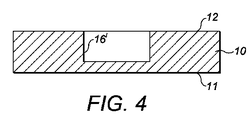
図1、2及び3の突起9又は9’と係合するのに適した凹部16’の代替形態が、図4の断面図に示されている。この実施形態では、凹部はプレート10’の円筒空洞である。図4において、円筒状の開口部は、プレートの厚さの部分的にのみ広がっている。しかし、円筒状の開口部は、プレートの第1及び第2の面11、12の両方に円形の開口部を形成するように、プレートの全層を貫いて広がっていても構わない。
An alternative form of recess 16 'suitable for engaging the
図1の実施形態では、プレート10は、摩擦によってアブミ骨底上の所定の位置に保持されている。しかし、他の実施形態では、プレートは、クリップによってアブミ骨底15の所定の位置に保持されても構わない。
In the embodiment of FIG. 1, the
図5は、例えばアブミ骨底15に対する図1の埋め込み型装置のプレート10等の埋め込み型デバイスを取り付けるのに適したクリップ50を示す。明確にするために、クリップはアブミ骨22の図の横に表示される。
FIG. 5 shows a
クリップ50は、アブミ骨のアーチ13をつかむための第1及び第2の湾曲部52、53を有するように形成された超弾性材料の連続ストリップ51を備え、略M字型のバネ部54によって接続されている。
The
第1及び第2の湾曲部52、53は、ストリップ51のそれぞれの端部によって形成され、これらは略半円状の又はC型状の円弧に形成され、第1の平面に平行であり、その凹面55、56が対向するように形成される。各湾曲部の端部では、ストリップは湾曲部から離れるように延びており、第2の平面はバネ部54を形成するために第1の平面に略垂直である。この第2の平面内で、ストリップはそれぞれの湾曲部から延びており、直線路57に沿って、それぞれの湾曲部の端部において半円状のアークの接線に対して約80度の角度である。湾曲部からの垂直距離において、それはアブミ骨底から平均的な大きさのアブミ骨の頸部への垂直距離に略等しく、ストリップは略半円弧58を形成するために、各湾曲部から離れて、また約180度の角度で曲げられる。これらの半円弧は略U字状部59によって接続されており、その最低部60は実質的に第1及び第2の平面の交点と一致している。
The first and second
第1及び第2の湾曲部52、53は、アブミ骨のアーチ13の外側対向面20の形態に対応するように構成される。接続バネ部54は湾曲部を接続するように形成され、外力がない場合に、湾曲部の凹面55、56の間の最大距離は、アブミ骨底15と接触する領域においてアブミ骨のアーチの外側に向く面の間の距離よりも小さくなる。
The first and second
接続バネ部54はまた、クリップ50が弾性変形されるように構成され、これにより、湾曲部がアブミ骨のアーチ13の周りを通過するように、十分な間隔で湾曲部52、53の間の間隔を広げることができる。
The connecting
特に、接続バネ部のM字型の形状は、ここにおいてM字の形状は比較的長い形状であり、図5において円Aで示される領域の偏差が、バネ部が超弾性モードで動作するのに充分であることを確保し、そこにおいて、力は偏差の広い範囲にわたってほぼ一定である。円Aで識別される領域は、クリップがアブミ骨のアーチをつかむように変形されたときに最も変形する領域である。 In particular, the M-shaped shape of the connecting spring portion is a relatively long shape, and the deviation of the region indicated by the circle A in FIG. 5 indicates that the spring portion operates in the superelastic mode. In which the force is approximately constant over a wide range of deviations. The area identified by the circle A is the area most deformed when the clip is deformed to grab the stapes of the stapes.
アブミ骨22にクリップ50を取り付けるには、ストリップ51の両端間の距離が、アブミ骨のアーチ13の外側対向面20の間の最大距離より大きくなるまで、接続バネ部54の作用に反して、クリップの第1及び第2の湾曲部52、53は外科医によって引き離される。この状態で、アーチがアブミ骨底15に接触する領域において、クリップの第1及び第2の湾曲部は各アーチの周りを通過し、クリップは、第1の平面がアブミ骨底15の表面14と平行となるように方向づけられる。クリップの端部はその後解放される。クリップの端部が解放さると、接続バネ部は、しっかりとアブミ骨の各アーチをつかむために、第1及び第2の湾曲部を同時に引っ張る。
To attach the
クリップ50の超弾性特性は、湾曲部52、53が接続バネ部54の偏差の広い範囲にわたって略一定の力を発揮することを意味する。したがって、特定の大きさのクリップは、アブミ骨のアーチ13に対して、あまりにも力を加え過ぎたり少なすぎたりするリスクなしに、アブミ骨22の大きさの大幅な変動に対応できる。
The superelastic characteristic of the
アブミ骨にクリップ50を取り付けると、第1及び第2の湾曲部52、53は、アブミ骨底15の表面14に沿って延びるか、近接する。接続バネ部54のU字型部59の底部60はまた、アブミ骨底15に接触するか、近接する。U字型部は、このように、他の要素が取り付けられたり、アブミ骨底に接触するような表面を提供する。
When the
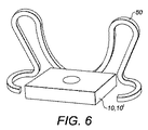
たとえば、図5のクリップ50は、例えば図1、2及び3のプレート10、10’のようなプレートをアブミ骨底15に結合するために使用することができる。このケースでは、プレートは、図6に示すような、クリップのU字型部59の底部60に結合されてもよい。したがって、上記のようにクリップがアブミ骨のアーチ13に取り付けられたときに、プレートは上にアブミ骨底に配置され、アブミ骨底と接触する。
For example, the
図7a〜7cはそれぞれ、人工中耳1’の形式をとる本発明の実施形態の正面、背面及び斜視図を示す。人工中耳1’は、図1〜3に関連して上述されたロッドとプレートの取り合わせを備え、プレート10は図5、6に示すクリップ50によりアブミ骨底に取り付けることができる。 Figures 7a-7c each show a front, back and perspective view of an embodiment of the present invention in the form of a cochlear implant 1 '. The cochlear implant 1 'comprises a rod and plate combination as described above in connection with FIGS.
人工中耳は、キヌタ骨の長い突起に係合するための超弾性バネクリップ5’を備える。バネクリップは、トランスデューサ素子(図示せず)に対する筐体4’の第1の側面にロッドで接続されている。ロッド7’は、筐体の第1の側面の反対側の第2の側面から延びており、略半球状の突起9’で終了する。環状溝31は、突起の半球部30に直接隣接するロッドに形成されている。
The artificial middle ear includes a super elastic spring clip 5 'for engaging the long protrusion of the quinuta bone. The spring clip is connected to the first side surface of the housing 4 'with respect to the transducer element (not shown) by a rod. The rod 7 'extends from a second side opposite to the first side of the housing and ends with a substantially hemispherical projection 9'. The
ロッド7’、つまり筐体4’とバネクリップ5’が回動自在にプレート10に取り付けられるように、突起9’は、プレートの中央領域に突起9’に応じて形成された空洞16に配置される。
The
プレート10の側面70は、その第1及び第2の面11、12のいずれかに垂直であり、クリップ50に溶接あるいは接合されている。具体的には、プレートの側面は、クリップのU字型部59の最低領域60に接合されている。
The
図7a〜7cに示される人工中耳1’を埋め込むために、第1及び第2の湾曲部52、53はアブミ骨のアーチ13の周囲に配置され、図5及び6に関連して記載されたように、プレート10はその中央部において、アブミ骨底15に配置され又は接触する。
To implant the cochlear implant 1 ′ shown in FIGS. 7a-7c, first and second
図1の実施形態に関連して上述したように、ロッド7’の端部の突起9’はその後凹部16に配置され、人工中耳1’は所定の位置に回転される。
As described above in connection with the embodiment of FIG. 1, the protrusion 9 'at the end of the rod 7' is then placed in the
本発明の別の実施形態では、ロッドの端部の突起を受ける凹部は、クリップと一体に形成されても構わない。 In another embodiment of the present invention, the recess that receives the protrusion at the end of the rod may be formed integrally with the clip.
図8は、アブミ骨のアーチに取り付けるためのクリップ80を示し、これは、クリップに応じて形成された突起を受け取るため円筒状の凹部16’を備える。
FIG. 8 shows a
クリップ80は、2つの比較的短い側面部81、82と2つの比較的長い側面部83、84を備え、これらは共に略長方形の枠を形成する。
The
2つの短い側面部81、82と長い側面部83の1つは比較的薄く、3つの凹面状の外縁85、86、87を形成するように曲線が内側に向いている。第4の側面部84は比較的広く、フレームの第4の外縁88を形成する直線縁と、フレームの端85〜88によって定義された開口部91に突出する略半円部90を定義する湾曲した内縁89を有する。
One of the two
第4の側面部84はこのようにクリップの板状領域を形成し、フレームの端85〜88に垂直な第1及び第2の面11’、12’を有する。円筒状の凹部16’は、半円形部90に部分的に配置されるように、板状領域の第2の面12’の、2つの短い側面部81、82の間の略中央に形成され、直線状の外縁88と湾曲した内縁89に近接している。円筒状の凹部は、クリップの略半分の厚さに渡っている。
The
クリップ80の2つの短い側面部81、82は、アブミ骨のアーチ13の内側対向面21の形状に対応して構成され、アブミ骨底の真上の領域において、その凹面との間の最短距離がアブミ骨のアーチの内接面の間の距離よりも若干長くなるように離間している。
The two
クリップ80は超弾性材料で形成されており、従って、アブミ骨のアーチ13を貫通するように弾性変形することができ、大きさの異なるアブミ骨に対して略一定の力を及ぼすことができる。
The
アブミ骨22にクリップ80を取り付けるには、外科医は、クリップの中央部で長い辺部83、84を互いの方に動かしてクリップを変形させる。この動作は、短い側面部81、82を引いてフレームの側面でまとめて、そこで長い側面部83に接触させて、クリップのこの側面がアブミ骨のアーチ13の間に挿入することができるようにする。
To attach the
この場合、クリップ80はアブミ骨アーチ13を貫通し、プレート領域の第1の表面11’がアブミ底板15の表面14に載るように配置される。
In this case, the
クリップ80は、その後、外科医によって放され、短い側面部81、82がアブミ骨のアーチ13の内側対向面21をつかむために跳ね上がり、これによってアブミ骨底15にプレート領域を保持する。
The
図5、6の実施形態と同様に、クリップの超弾性特性は、湾曲部が接続バネ部の偏差の広い範囲にわたって略一定の力を発揮することを意味する。したがって、特定の大きさのクリップは、アブミ骨のアーチにあまりにも多くの、または少なすぎる力を加えるリスクなしに、アブミ骨のアーチの大きさの大幅な変動に対応できる。 Similar to the embodiment of FIGS. 5 and 6, the superelastic characteristics of the clip means that the bending portion exerts a substantially constant force over a wide range of deviations of the connecting spring portion. Thus, a particular size clip can accommodate a large variation in the size of the stapes arch without the risk of applying too much or too little force to the stapes arch.
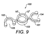
図9は、アブミ骨のアーチ13に取り付けるための別のアブミ骨クリップ100を示し、それに応じて形成された突起を受けるため円筒状の凹部16’を備える。
FIG. 9 shows another
アブミ骨クリップ100は、第1及び第2のC字型部101、102を備え、アブミ骨のアーチ13を係合するために、中央の接続部103の両側に接続される。
The stapes clip 100 includes first and second C-shaped
中央の接続部103は略円形であり、アブミ骨底15に接触する第1の面11’’と、第1の面の反対側に円筒状の凹部16’が形成された第2の面12’’を有する。
The
図9を見ると、右側C型部101は円の優弧を規定し、クリップ100の縦軸に垂直である開口部104を形成するために、その端部の間は1つのアブミ骨のアーチ13の直径よりも大きく離間している。右側C型部は、このように第1のアブミ骨のアーチにスライドすることができる。
Referring to FIG. 9, the right C-shaped
図9を見ると、左側C型部102は同様に円の優弧を規定する。この優弧の両端は、クリップ100の縦軸に平行な開口部105を形成する。右側C型部が第1のアーチの周りに配置されているときに、左側C型部は第2のアブミ骨のアーチにスライドするのに十分な幅を有する。左側C型部は、アブミ骨のアーチの離間距離に対応するのに十分な幅であるように形成されていても構わない。
Referring to FIG. 9, the left C-shaped
アブミ骨22にクリップ100を取り付けるために、アブミ骨底15にアーチが接触する領域において、右側C型部101は第1のアブミ骨のアーチ13にスライドする。第1のアブミ骨のアーチ上に右側C型部101を取り付けつつ、外科医は、左側C型部102がクリップを適所に保持するために第2のアブミ骨の周りに延在するまでクリップ100を反時計回りに回転させる。この構成では、クリップ100は、左側C型部102の係合が解除されることなく、アブミ骨22に対してもはや回転することはできず、中央の連結部103の第1の面11’’は、アブミ骨底15の中心部に接触する。
In order to attach the
図1〜4に関連して述べたように、アブミ骨底15の他の要素に結合するために、適切に形成された突起は円筒状の凹部16’に配置することができる。 As described in connection with FIGS. 1-4, a suitably shaped protrusion can be placed in the cylindrical recess 16 'for coupling to other elements of the stapes 15.
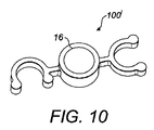
図10は図9と同様なクリップ100’を示し、円筒状の凹部16’は略半球状の凹部16に置き換えられている。
FIG. 10 shows a
アブミ骨底に埋め込み型装置を係合するための別のアブミ骨クリップ110、110’、110’’、110’’’が図11a〜11dに説明される。これらの各実施形態は、アブミ骨と接触する領域において、アブミ骨のアーチに係合するための湾曲部111、111’、111’’、111’’’と、クリップが弾性的にアブミ骨アーチの周りを通過するか、又はその間を通過するように変形することができ、バネを適所に保持するためにアブミ骨のアーチを押し付ける連結バネ部112、112’、112’’、112’’’を備える。
Alternative stapes clips 110, 110 ', 110 ", 110" "for engaging the implantable device with the stapes floor are illustrated in Figs. Each of these embodiments includes a
特に、図11aの実施形態では、アブミ骨のアーチの周りに湾曲部111を覆うために、クリップは端部を外側に引き出すことができるコイルバネ112を備える。クリップをアブミ骨のアーチの間に配置したときに、コイルバネは元の形状に戻ろうとし、アブミ骨底の適切な位置にクリップを保持するために、湾曲部をアブミ骨のアーチの外側対向面に押しつけるようになる。
In particular, in the embodiment of FIG. 11a, the clip comprises a
図11cの実施形態において、連結バネ部112’’は第1及び第2の曲り梁を備え、それぞれが第1及び第2の湾曲部に接続されている。湾曲部111’’は、クリップがアブミ骨のアーチの間に挿入できるようにするために、変形性の曲り梁112’’を内側へ押すことができる。クリップがアブミ骨のアーチの間に配置されている場合、曲り梁は元の位置に戻ろうとし、アブミ骨底の所定の位置にクリップを保持するために、湾曲部111’’をアブミ骨アーチの内側対向面に押しつけるようになる。 In the embodiment of FIG. 11c, the connecting spring portion 112 '' includes first and second bent beams, which are connected to the first and second curved portions, respectively. The bend 111 '' can push the deformable curved beam 112 '' inward to allow the clip to be inserted between the stapes of the stapes. When the clip is placed between the stapes of the stapes, the curved beam tries to return to its original position and the bend 111 '' is placed over the stapes arch to hold the clip in place on the stapes It comes to press against the inner facing surface.
プレート又はその他の要素は、さらに、埋め込み型要素にクリップを結合するために、図11a〜11dのクリップのそれぞれに結合又は取り付けられる。また、円形の凹部は、凹部に対応して形成された突起を受けるために、図11cのクリップの中央部113に形成されてもかまわない。
A plate or other element is further coupled or attached to each of the clips of FIGS. 11a-11d to couple the clip to the implantable element. In addition, the circular recess may be formed in the
一般に、本発明の弾力性クリップ又は付着手段は十分に変形するように構成され、元の又は自然の構成から、係合部がアブミ骨のアーチを係合する構成に変形するときは、クリップは超弾性的にアブミ骨のアーチに係合する。その結果、クリップの係合部によってアーチにかかる力は、偏差の広い範囲にわたってほぼ一定である。これにより、所定の大きさのクリップは、患者間の解剖学的な大きな変化に対応できるようになる。 In general, the resilient clip or attachment means of the present invention is configured to be sufficiently deformed so that when the engagement portion is deformed from an original or natural configuration to a configuration that engages the stapes of the stapes, Superelastically engages the stapes arch. As a result, the force applied to the arch by the engaging portion of the clip is substantially constant over a wide range of deviations. This allows clips of a predetermined size to accommodate large anatomical changes between patients.
クリップがアブミ骨のアーチに係合するように変形されたときに、クリップの接続バネ部の特定の領域において十分な偏差を確保するために、取付手段を構成することによって達成されても構わない。 It may be achieved by configuring the attachment means to ensure a sufficient deviation in a particular region of the connection spring portion of the clip when the clip is deformed to engage the stapes of the stapes. .
例えば、図5のクリップ50は、クリップが超弾性範囲で動作するために、クリップがアブミ骨のアーチに係合するように変形するときに、円Aで示される領域が充分に変形するように構成される。他の例では、図11bのクリップ111’は、クリップが超弾性範囲で動作するために、クリップがアブミ骨のアーチに係合するように変形するときに、円Aで示される領域が充分に変形するように構成される。また別の例では、図11dのクリップ111’’’は、クリップが超弾性範囲で動作するために、クリップがアブミ骨のアーチに係合するように変形するときに、円Aで示される領域が充分に変形するように構成される。
For example, the
本発明は、キヌタ骨の長い突起からアブミ骨底に延びる聴覚アクチュエータの観点から上述されている。しかし、本発明の原理は、受動型及び能動型の両方の人工中耳の他のタイプにも等しく適用され、これは、中耳の他の一部からアブミ骨底に延びるように構成されるか、又は中耳の外部に配置される。しかしながら、好ましくは、本発明の人工中耳は、アブミ骨自体以外の要素の第2の付着領域からアブミ骨底に延びるように構成される。 The present invention has been described above in terms of an auditory actuator that extends from the long projections of the quinuta bone to the stapes. However, the principles of the present invention apply equally to other types of both the passive and active cochlear implants, which are configured to extend from the other part of the middle ear to the stapes. Or placed outside the middle ear. However, preferably, the artificial middle ear of the present invention is configured to extend from the second attachment region of an element other than the stapes itself to the stapes bottom.
本発明はまた、実施形態に関して記載されており、ここにおいて、開口部又は凹部はアブミ骨底の係合部に形成され、対応する突起は人工中耳の伸張部の端部に形成されている。しかし、当然のことながら、凹部は人工中耳の伸張部上に形成することができ、突起はアブミ骨底係合部上に形成することができる。 The present invention has also been described with respect to an embodiment, wherein an opening or recess is formed in the engaging portion of the stapes and a corresponding protrusion is formed at the end of the extension of the artificial middle ear. . However, it will be appreciated that the recess can be formed on the extension of the artificial middle ear and the protrusion can be formed on the stapes bottom engaging portion.
Claims (18)
前記係合部(52)、(53)の係合面(55)、(56)は、前記アブミ骨のアーチの各々と係合するときに、アブミ骨底上に位置するアブミ骨底係合部(10)を備え、
前記アブミ骨底係合部(10)は開口部(16)と突起のうちの1つを備え、結合部(7’)の対応する突起(9’)又は開口部を受けてこれらが前記結合部(7’)との枢軸結合を形成する取付手段。 An attachment means for attaching the implantable device to the floor of the stapes, wherein the implantable device has a joint (7 ') with an opening or a projection (9'), the attachment means comprising a connecting part first and second engaging portions that are connected by (54) (52), provided with (53), said engaging portion (52), each (53) is engaged to each of the arch stapes Engagement surfaces (55), (56) configured to
The engaging surfaces (55), (56) of the engaging portions (52), (53) , when engaged with each of the stapes of the stapes, are located on the floor of the stapes. Part (10) ,
The stapes bottom engaging portion (10) is provided with one of an opening (16) and a protrusion, which receives the corresponding protrusion (9 ') or opening of the connecting portion (7') and these are connected to each other. part (7 ') and means Mounting that form a pivot coupling.
The attachment means according to any one of claims 1 to 17 , wherein the attachment means is formed of a biocompatible material.
Applications Claiming Priority (3)
| Application Number | Priority Date | Filing Date | Title |
|---|---|---|---|
| GBGB0910906.7A GB0910906D0 (en) | 2009-06-24 | 2009-06-24 | Coupling apparatus |
| GB0910906.7 | 2009-06-24 | ||
| PCT/GB2010/051046 WO2010150016A1 (en) | 2009-06-24 | 2010-06-24 | Coupling apparatus |
Publications (3)
| Publication Number | Publication Date |
|---|---|
| JP2012530584A JP2012530584A (en) | 2012-12-06 |
| JP2012530584A5 JP2012530584A5 (en) | 2013-08-08 |
| JP5695038B2 true JP5695038B2 (en) | 2015-04-01 |
Family
ID=40972713
Family Applications (1)
| Application Number | Title | Priority Date | Filing Date |
|---|---|---|---|
| JP2012516862A Expired - Fee Related JP5695038B2 (en) | 2009-06-24 | 2010-06-24 | Coupling device |
Country Status (9)
| Country | Link |
|---|---|
| US (1) | US20120158135A1 (en) |
| EP (1) | EP2445449A1 (en) |
| JP (1) | JP5695038B2 (en) |
| KR (1) | KR20120052234A (en) |
| CN (1) | CN102458307A (en) |
| AU (1) | AU2010264286A1 (en) |
| CA (1) | CA2768546A1 (en) |
| GB (1) | GB0910906D0 (en) |
| WO (1) | WO2010150016A1 (en) |
Families Citing this family (3)
| Publication number | Priority date | Publication date | Assignee | Title |
|---|---|---|---|---|
| ES2407868T3 (en) * | 2011-01-29 | 2013-06-14 | Heinz Kurz Gmbh Medizintechnik | Hearing aid for ossicular replacement with stabilizing element |
| DE102014114494A1 (en) * | 2014-10-07 | 2016-04-07 | Heinz Kurz Gmbh Medizintechnik | Active hearing implant with adjustable fixation of the actuator end piece in the middle ear |
| CN114452035A (en) * | 2022-04-08 | 2022-05-10 | 杭州师范大学附属医院(杭州市第二人民医院) | Soft clip type artificial stapes prosthesis |
Family Cites Families (13)
| Publication number | Priority date | Publication date | Assignee | Title |
|---|---|---|---|---|
| DD259566A1 (en) * | 1987-04-13 | 1988-08-31 | Hermsdorf Keramik Veb | GEHOERNKNOECHELCHEN-GRAFT |
| US5531787A (en) * | 1993-01-25 | 1996-07-02 | Lesinski; S. George | Implantable auditory system with micromachined microsensor and microactuator |
| JPH06339489A (en) * | 1993-02-26 | 1994-12-13 | Asahi Optical Co Ltd | Artificial auditory ossicle |
| DE19700813A1 (en) * | 1997-01-13 | 1998-07-16 | Eberhard Prof Dr Med Stennert | Middle ear prosthesis |
| DE29701534U1 (en) * | 1997-01-30 | 1997-03-27 | Voit Sven | Device for holding two pieces of cutlery in tongs |
| DE202004001008U1 (en) * | 2004-01-23 | 2004-04-01 | Heinz Kurz Gmbh Medizintechnik | ossicle prosthesis |
| AT7627U1 (en) * | 2004-02-26 | 2005-06-27 | Verdichter Oe Ges M B H | REFRIGERANT COMPRESSOR |
| GB0500616D0 (en) * | 2005-01-13 | 2005-02-23 | Univ Dundee | Hearing implant |
| DE202006002196U1 (en) * | 2005-07-21 | 2006-04-27 | Heinz Kurz Gmbh Medizintechnik | ossicle prosthesis |
| DE102005048618B4 (en) * | 2005-10-11 | 2008-08-21 | Heinz Kurz Gmbh Medizintechnik | Auditory ossicle prosthesis with elastic swivel joint |
| GB2449114A (en) * | 2007-05-11 | 2008-11-12 | Sentient Medical Ltd | Middle ear implant with piezoelectric actuator acting on stapes footplate |
| KR100931209B1 (en) * | 2007-11-20 | 2009-12-10 | 경북대학교 산학협력단 | Easy-to-install garden-driven vibration transducer and implantable hearing aid using it |
| DE202007017910U1 (en) * | 2007-12-21 | 2008-03-13 | Heinz Kurz Gmbh Medizintechnik | Modular Middle Ear Full Prosthesis |
-
2009
- 2009-06-24 GB GBGB0910906.7A patent/GB0910906D0/en not_active Ceased
-
2010
- 2010-06-24 KR KR1020127001487A patent/KR20120052234A/en not_active Application Discontinuation
- 2010-06-24 JP JP2012516862A patent/JP5695038B2/en not_active Expired - Fee Related
- 2010-06-24 CA CA2768546A patent/CA2768546A1/en not_active Abandoned
- 2010-06-24 US US13/380,755 patent/US20120158135A1/en not_active Abandoned
- 2010-06-24 EP EP10739977A patent/EP2445449A1/en not_active Withdrawn
- 2010-06-24 AU AU2010264286A patent/AU2010264286A1/en not_active Abandoned
- 2010-06-24 WO PCT/GB2010/051046 patent/WO2010150016A1/en active Application Filing
- 2010-06-24 CN CN2010800327136A patent/CN102458307A/en active Pending
Also Published As
| Publication number | Publication date |
|---|---|
| KR20120052234A (en) | 2012-05-23 |
| WO2010150016A1 (en) | 2010-12-29 |
| AU2010264286A1 (en) | 2012-02-16 |
| GB0910906D0 (en) | 2009-08-05 |
| CA2768546A1 (en) | 2010-12-29 |
| CN102458307A (en) | 2012-05-16 |
| US20120158135A1 (en) | 2012-06-21 |
| EP2445449A1 (en) | 2012-05-02 |
| JP2012530584A (en) | 2012-12-06 |
Similar Documents
| Publication | Publication Date | Title |
|---|---|---|
| US7011683B2 (en) | Attachment mechanism for middle ear prosthesis | |
| US7871439B2 (en) | Auditory ossicle prosthesis with tuning option | |
| US7628812B2 (en) | Ossicle prosthesis | |
| AU741406B2 (en) | Arrangement for mechanical coupling of a driver to a coupling site of the ossicular chain | |
| US8906090B2 (en) | Auditory ossicle prosthesis | |
| US20120197066A1 (en) | Coupling apparatus | |
| US20060241755A1 (en) | Stapedial Prosthesis and Method of Implanting the Same | |
| CA2776125A1 (en) | Improved middle ear implant and method | |
| JP5695038B2 (en) | Coupling device | |
| AU761810B2 (en) | Otologic prostheses | |
| US20080058927A1 (en) | Ossicular Prostheses Fabricated From Shape Memory Polymers | |
| US20080097603A1 (en) | Otologic Prostheses With Compressive Ossicular Engagement By An Elastic Structure And Method Of Implanting The Same | |
| US9730789B2 (en) | Ossicular prosthesis having a longitudinally perforated bight | |
| US8641760B2 (en) | Ossicular prosthesis with stabilizer and method of use with intact stapes | |
| CN116157095A (en) | Ossicular prosthesis | |
| US20150045884A1 (en) | Stapes prosthesis with snap closure |
Legal Events
| Date | Code | Title | Description |
|---|---|---|---|
| A521 | Written amendment |
Free format text: JAPANESE INTERMEDIATE CODE: A523 Effective date: 20130624 |
|
| A621 | Written request for application examination |
Free format text: JAPANESE INTERMEDIATE CODE: A621 Effective date: 20130624 |
|
| A977 | Report on retrieval |
Free format text: JAPANESE INTERMEDIATE CODE: A971007 Effective date: 20140523 |
|
| A131 | Notification of reasons for refusal |
Free format text: JAPANESE INTERMEDIATE CODE: A131 Effective date: 20140527 |
|
| A601 | Written request for extension of time |
Free format text: JAPANESE INTERMEDIATE CODE: A601 Effective date: 20140827 |
|
| A602 | Written permission of extension of time |
Free format text: JAPANESE INTERMEDIATE CODE: A602 Effective date: 20140903 |
|
| A521 | Written amendment |
Free format text: JAPANESE INTERMEDIATE CODE: A523 Effective date: 20141127 |
|
| TRDD | Decision of grant or rejection written | ||
| A01 | Written decision to grant a patent or to grant a registration (utility model) |
Free format text: JAPANESE INTERMEDIATE CODE: A01 Effective date: 20150106 |
|
| A61 | First payment of annual fees (during grant procedure) |
Free format text: JAPANESE INTERMEDIATE CODE: A61 Effective date: 20150205 |
|
| R150 | Certificate of patent or registration of utility model |
Ref document number: 5695038 Country of ref document: JP Free format text: JAPANESE INTERMEDIATE CODE: R150 |
|
| LAPS | Cancellation because of no payment of annual fees |