JP5692644B2 - Battery, battery separator, and battery separator manufacturing method - Google Patents
Battery, battery separator, and battery separator manufacturing method Download PDFInfo
- Publication number
- JP5692644B2 JP5692644B2 JP2011061314A JP2011061314A JP5692644B2 JP 5692644 B2 JP5692644 B2 JP 5692644B2 JP 2011061314 A JP2011061314 A JP 2011061314A JP 2011061314 A JP2011061314 A JP 2011061314A JP 5692644 B2 JP5692644 B2 JP 5692644B2
- Authority
- JP
- Japan
- Prior art keywords
- material layer
- negative electrode
- positive electrode
- active material
- separator
- Prior art date
- Legal status (The legal status is an assumption and is not a legal conclusion. Google has not performed a legal analysis and makes no representation as to the accuracy of the status listed.)
- Active
Links
- 238000004519 manufacturing process Methods 0.000 title claims description 8
- 239000011888 foil Substances 0.000 claims description 63
- 239000000463 material Substances 0.000 claims description 49
- 239000007774 positive electrode material Substances 0.000 claims description 36
- 239000007773 negative electrode material Substances 0.000 claims description 34
- 238000010248 power generation Methods 0.000 claims description 9
- 238000010030 laminating Methods 0.000 claims description 5
- 239000011149 active material Substances 0.000 claims description 2
- 238000003825 pressing Methods 0.000 claims description 2
- -1 polyethylene Polymers 0.000 description 9
- 229920000098 polyolefin Polymers 0.000 description 8
- 229920005989 resin Polymers 0.000 description 8
- 239000011347 resin Substances 0.000 description 8
- 239000000919 ceramic Substances 0.000 description 6
- 229920001577 copolymer Polymers 0.000 description 6
- 239000011255 nonaqueous electrolyte Substances 0.000 description 6
- 239000000843 powder Substances 0.000 description 6
- VYPSYNLAJGMNEJ-UHFFFAOYSA-N Silicium dioxide Chemical compound O=[Si]=O VYPSYNLAJGMNEJ-UHFFFAOYSA-N 0.000 description 4
- GWEVSGVZZGPLCZ-UHFFFAOYSA-N Titan oxide Chemical compound O=[Ti]=O GWEVSGVZZGPLCZ-UHFFFAOYSA-N 0.000 description 4
- 239000002131 composite material Substances 0.000 description 4
- 239000008151 electrolyte solution Substances 0.000 description 4
- 150000004678 hydrides Chemical class 0.000 description 3
- 238000009413 insulation Methods 0.000 description 3
- 238000000034 method Methods 0.000 description 3
- 229920000728 polyester Polymers 0.000 description 3
- VTYYLEPIZMXCLO-UHFFFAOYSA-L Calcium carbonate Chemical compound [Ca+2].[O-]C([O-])=O VTYYLEPIZMXCLO-UHFFFAOYSA-L 0.000 description 2
- 229920002134 Carboxymethyl cellulose Polymers 0.000 description 2
- 239000004354 Hydroxyethyl cellulose Substances 0.000 description 2
- 229920000663 Hydroxyethyl cellulose Polymers 0.000 description 2
- UQSXHKLRYXJYBZ-UHFFFAOYSA-N Iron oxide Chemical compound [Fe]=O UQSXHKLRYXJYBZ-UHFFFAOYSA-N 0.000 description 2
- WHXSMMKQMYFTQS-UHFFFAOYSA-N Lithium Chemical compound [Li] WHXSMMKQMYFTQS-UHFFFAOYSA-N 0.000 description 2
- CPLXHLVBOLITMK-UHFFFAOYSA-N Magnesium oxide Chemical compound [Mg]=O CPLXHLVBOLITMK-UHFFFAOYSA-N 0.000 description 2
- 239000004698 Polyethylene Substances 0.000 description 2
- 239000004372 Polyvinyl alcohol Substances 0.000 description 2
- XLOMVQKBTHCTTD-UHFFFAOYSA-N Zinc monoxide Chemical compound [Zn]=O XLOMVQKBTHCTTD-UHFFFAOYSA-N 0.000 description 2
- MCMNRKCIXSYSNV-UHFFFAOYSA-N Zirconium dioxide Chemical compound O=[Zr]=O MCMNRKCIXSYSNV-UHFFFAOYSA-N 0.000 description 2
- PNEYBMLMFCGWSK-UHFFFAOYSA-N aluminium oxide Inorganic materials [O-2].[O-2].[O-2].[Al+3].[Al+3] PNEYBMLMFCGWSK-UHFFFAOYSA-N 0.000 description 2
- 150000001875 compounds Chemical class 0.000 description 2
- 230000000694 effects Effects 0.000 description 2
- 239000003792 electrolyte Substances 0.000 description 2
- 235000019447 hydroxyethyl cellulose Nutrition 0.000 description 2
- NLYAJNPCOHFWQQ-UHFFFAOYSA-N kaolin Chemical compound O.O.O=[Al]O[Si](=O)O[Si](=O)O[Al]=O NLYAJNPCOHFWQQ-UHFFFAOYSA-N 0.000 description 2
- 229910052744 lithium Inorganic materials 0.000 description 2
- 238000002844 melting Methods 0.000 description 2
- 230000008018 melting Effects 0.000 description 2
- 238000012986 modification Methods 0.000 description 2
- 230000004048 modification Effects 0.000 description 2
- 229920002492 poly(sulfone) Polymers 0.000 description 2
- 229920002037 poly(vinyl butyral) polymer Polymers 0.000 description 2
- 229920000573 polyethylene Polymers 0.000 description 2
- 229920002451 polyvinyl alcohol Polymers 0.000 description 2
- 229920000036 polyvinylpyrrolidone Polymers 0.000 description 2
- 239000001267 polyvinylpyrrolidone Substances 0.000 description 2
- 235000013855 polyvinylpyrrolidone Nutrition 0.000 description 2
- 239000002994 raw material Substances 0.000 description 2
- 239000000377 silicon dioxide Substances 0.000 description 2
- 239000000758 substrate Substances 0.000 description 2
- FEIQOMCWGDNMHM-UHFFFAOYSA-N 5-phenylpenta-2,4-dienoic acid Chemical compound OC(=O)C=CC=CC1=CC=CC=C1 FEIQOMCWGDNMHM-UHFFFAOYSA-N 0.000 description 1
- 239000005995 Aluminium silicate Substances 0.000 description 1
- 229910052582 BN Inorganic materials 0.000 description 1
- PZNSFCLAULLKQX-UHFFFAOYSA-N Boron nitride Chemical compound N#B PZNSFCLAULLKQX-UHFFFAOYSA-N 0.000 description 1
- 239000004709 Chlorinated polyethylene Substances 0.000 description 1
- HBBGRARXTFLTSG-UHFFFAOYSA-N Lithium ion Chemical compound [Li+] HBBGRARXTFLTSG-UHFFFAOYSA-N 0.000 description 1
- CERQOIWHTDAKMF-UHFFFAOYSA-N Methacrylic acid Chemical compound CC(=C)C(O)=O CERQOIWHTDAKMF-UHFFFAOYSA-N 0.000 description 1
- 239000002033 PVDF binder Substances 0.000 description 1
- 239000004962 Polyamide-imide Substances 0.000 description 1
- 239000004697 Polyetherimide Substances 0.000 description 1
- 239000004734 Polyphenylene sulfide Substances 0.000 description 1
- 239000004743 Polypropylene Substances 0.000 description 1
- 229910052581 Si3N4 Inorganic materials 0.000 description 1
- NRTOMJZYCJJWKI-UHFFFAOYSA-N Titanium nitride Chemical compound [Ti]#N NRTOMJZYCJJWKI-UHFFFAOYSA-N 0.000 description 1
- 229910021536 Zeolite Inorganic materials 0.000 description 1
- XECAHXYUAAWDEL-UHFFFAOYSA-N acrylonitrile butadiene styrene Chemical compound C=CC=C.C=CC#N.C=CC1=CC=CC=C1 XECAHXYUAAWDEL-UHFFFAOYSA-N 0.000 description 1
- 239000004676 acrylonitrile butadiene styrene Substances 0.000 description 1
- 229920000122 acrylonitrile butadiene styrene Polymers 0.000 description 1
- 239000000956 alloy Substances 0.000 description 1
- 229910045601 alloy Inorganic materials 0.000 description 1
- WNROFYMDJYEPJX-UHFFFAOYSA-K aluminium hydroxide Chemical compound [OH-].[OH-].[OH-].[Al+3] WNROFYMDJYEPJX-UHFFFAOYSA-K 0.000 description 1
- 235000012211 aluminium silicate Nutrition 0.000 description 1
- DIZPMCHEQGEION-UHFFFAOYSA-H aluminium sulfate (anhydrous) Chemical compound [Al+3].[Al+3].[O-]S([O-])(=O)=O.[O-]S([O-])(=O)=O.[O-]S([O-])(=O)=O DIZPMCHEQGEION-UHFFFAOYSA-H 0.000 description 1
- HPTYUNKZVDYXLP-UHFFFAOYSA-N aluminum;trihydroxy(trihydroxysilyloxy)silane;hydrate Chemical compound O.[Al].[Al].O[Si](O)(O)O[Si](O)(O)O HPTYUNKZVDYXLP-UHFFFAOYSA-N 0.000 description 1
- 150000003863 ammonium salts Chemical class 0.000 description 1
- 239000003125 aqueous solvent Substances 0.000 description 1
- 239000010425 asbestos Substances 0.000 description 1
- 239000000440 bentonite Substances 0.000 description 1
- 229910000278 bentonite Inorganic materials 0.000 description 1
- SVPXDRXYRYOSEX-UHFFFAOYSA-N bentoquatam Chemical compound O.O=[Si]=O.O=[Al]O[Al]=O SVPXDRXYRYOSEX-UHFFFAOYSA-N 0.000 description 1
- 230000000903 blocking effect Effects 0.000 description 1
- 229910000019 calcium carbonate Inorganic materials 0.000 description 1
- 239000000378 calcium silicate Substances 0.000 description 1
- 229910052918 calcium silicate Inorganic materials 0.000 description 1
- OYACROKNLOSFPA-UHFFFAOYSA-N calcium;dioxido(oxo)silane Chemical compound [Ca+2].[O-][Si]([O-])=O OYACROKNLOSFPA-UHFFFAOYSA-N 0.000 description 1
- 239000003575 carbonaceous material Substances 0.000 description 1
- 239000001768 carboxy methyl cellulose Substances 0.000 description 1
- 235000010948 carboxy methyl cellulose Nutrition 0.000 description 1
- 239000008112 carboxymethyl-cellulose Substances 0.000 description 1
- 229920002678 cellulose Polymers 0.000 description 1
- 235000010980 cellulose Nutrition 0.000 description 1
- 239000012461 cellulose resin Substances 0.000 description 1
- CETPSERCERDGAM-UHFFFAOYSA-N ceric oxide Chemical compound O=[Ce]=O CETPSERCERDGAM-UHFFFAOYSA-N 0.000 description 1
- 229910000422 cerium(IV) oxide Inorganic materials 0.000 description 1
- 239000004927 clay Substances 0.000 description 1
- 229910052570 clay Inorganic materials 0.000 description 1
- 230000008602 contraction Effects 0.000 description 1
- 238000005520 cutting process Methods 0.000 description 1
- GUJOJGAPFQRJSV-UHFFFAOYSA-N dialuminum;dioxosilane;oxygen(2-);hydrate Chemical compound O.[O-2].[O-2].[O-2].[Al+3].[Al+3].O=[Si]=O.O=[Si]=O.O=[Si]=O.O=[Si]=O GUJOJGAPFQRJSV-UHFFFAOYSA-N 0.000 description 1
- HNPSIPDUKPIQMN-UHFFFAOYSA-N dioxosilane;oxo(oxoalumanyloxy)alumane Chemical compound O=[Si]=O.O=[Al]O[Al]=O HNPSIPDUKPIQMN-UHFFFAOYSA-N 0.000 description 1
- NJLLQSBAHIKGKF-UHFFFAOYSA-N dipotassium dioxido(oxo)titanium Chemical compound [K+].[K+].[O-][Ti]([O-])=O NJLLQSBAHIKGKF-UHFFFAOYSA-N 0.000 description 1
- 238000007599 discharging Methods 0.000 description 1
- 125000002573 ethenylidene group Chemical group [*]=C=C([H])[H] 0.000 description 1
- RTZKZFJDLAIYFH-UHFFFAOYSA-N ether Substances CCOCC RTZKZFJDLAIYFH-UHFFFAOYSA-N 0.000 description 1
- 229920006242 ethylene acrylic acid copolymer Polymers 0.000 description 1
- 239000005038 ethylene vinyl acetate Substances 0.000 description 1
- 229920006244 ethylene-ethyl acrylate Polymers 0.000 description 1
- 229920006225 ethylene-methyl acrylate Polymers 0.000 description 1
- 229920001973 fluoroelastomer Polymers 0.000 description 1
- 229910052621 halloysite Inorganic materials 0.000 description 1
- 229920006015 heat resistant resin Polymers 0.000 description 1
- 230000001771 impaired effect Effects 0.000 description 1
- 229910052622 kaolinite Inorganic materials 0.000 description 1
- 229910001416 lithium ion Inorganic materials 0.000 description 1
- 229910003002 lithium salt Inorganic materials 0.000 description 1
- 159000000002 lithium salts Chemical class 0.000 description 1
- HCWCAKKEBCNQJP-UHFFFAOYSA-N magnesium orthosilicate Chemical compound [Mg+2].[Mg+2].[O-][Si]([O-])([O-])[O-] HCWCAKKEBCNQJP-UHFFFAOYSA-N 0.000 description 1
- 239000000395 magnesium oxide Substances 0.000 description 1
- 239000000391 magnesium silicate Substances 0.000 description 1
- 229910052919 magnesium silicate Inorganic materials 0.000 description 1
- 235000019792 magnesium silicate Nutrition 0.000 description 1
- 239000000155 melt Substances 0.000 description 1
- 239000010445 mica Substances 0.000 description 1
- 229910052618 mica group Inorganic materials 0.000 description 1
- 229910052901 montmorillonite Inorganic materials 0.000 description 1
- 150000004767 nitrides Chemical class 0.000 description 1
- 239000002245 particle Substances 0.000 description 1
- 229920005575 poly(amic acid) Polymers 0.000 description 1
- 229920006122 polyamide resin Polymers 0.000 description 1
- 229920002312 polyamide-imide Polymers 0.000 description 1
- 229920001601 polyetherimide Polymers 0.000 description 1
- 229920000139 polyethylene terephthalate Polymers 0.000 description 1
- 239000005020 polyethylene terephthalate Substances 0.000 description 1
- 229920001721 polyimide Polymers 0.000 description 1
- 239000009719 polyimide resin Substances 0.000 description 1
- 229920001955 polyphenylene ether Polymers 0.000 description 1
- 229920000069 polyphenylene sulfide Polymers 0.000 description 1
- 229920001155 polypropylene Polymers 0.000 description 1
- 229920001343 polytetrafluoroethylene Polymers 0.000 description 1
- 239000004810 polytetrafluoroethylene Substances 0.000 description 1
- 229920002635 polyurethane Polymers 0.000 description 1
- 239000004814 polyurethane Substances 0.000 description 1
- 239000011118 polyvinyl acetate Substances 0.000 description 1
- 229920002689 polyvinyl acetate Polymers 0.000 description 1
- 229920002981 polyvinylidene fluoride Polymers 0.000 description 1
- 239000002243 precursor Substances 0.000 description 1
- KUKFKAPJCRZILJ-UHFFFAOYSA-N prop-2-enenitrile;prop-2-enoic acid Chemical compound C=CC#N.OC(=O)C=C KUKFKAPJCRZILJ-UHFFFAOYSA-N 0.000 description 1
- 229910052903 pyrophyllite Inorganic materials 0.000 description 1
- 229910052895 riebeckite Inorganic materials 0.000 description 1
- HBMJWWWQQXIZIP-UHFFFAOYSA-N silicon carbide Chemical compound [Si+]#[C-] HBMJWWWQQXIZIP-UHFFFAOYSA-N 0.000 description 1
- 229910010271 silicon carbide Inorganic materials 0.000 description 1
- HQVNEWCFYHHQES-UHFFFAOYSA-N silicon nitride Chemical compound N12[Si]34N5[Si]62N3[Si]51N64 HQVNEWCFYHHQES-UHFFFAOYSA-N 0.000 description 1
- 229920003048 styrene butadiene rubber Polymers 0.000 description 1
- 229920003051 synthetic elastomer Polymers 0.000 description 1
- 239000005061 synthetic rubber Substances 0.000 description 1
- 239000000454 talc Substances 0.000 description 1
- 229910052623 talc Inorganic materials 0.000 description 1
- RUDFQVOCFDJEEF-UHFFFAOYSA-N yttrium(III) oxide Inorganic materials [O-2].[O-2].[O-2].[Y+3].[Y+3] RUDFQVOCFDJEEF-UHFFFAOYSA-N 0.000 description 1
- 239000010457 zeolite Substances 0.000 description 1
- 239000011787 zinc oxide Substances 0.000 description 1
Images


Classifications
-
- Y—GENERAL TAGGING OF NEW TECHNOLOGICAL DEVELOPMENTS; GENERAL TAGGING OF CROSS-SECTIONAL TECHNOLOGIES SPANNING OVER SEVERAL SECTIONS OF THE IPC; TECHNICAL SUBJECTS COVERED BY FORMER USPC CROSS-REFERENCE ART COLLECTIONS [XRACs] AND DIGESTS
- Y02—TECHNOLOGIES OR APPLICATIONS FOR MITIGATION OR ADAPTATION AGAINST CLIMATE CHANGE
- Y02E—REDUCTION OF GREENHOUSE GAS [GHG] EMISSIONS, RELATED TO ENERGY GENERATION, TRANSMISSION OR DISTRIBUTION
- Y02E60/00—Enabling technologies; Technologies with a potential or indirect contribution to GHG emissions mitigation
- Y02E60/10—Energy storage using batteries
-
- Y—GENERAL TAGGING OF NEW TECHNOLOGICAL DEVELOPMENTS; GENERAL TAGGING OF CROSS-SECTIONAL TECHNOLOGIES SPANNING OVER SEVERAL SECTIONS OF THE IPC; TECHNICAL SUBJECTS COVERED BY FORMER USPC CROSS-REFERENCE ART COLLECTIONS [XRACs] AND DIGESTS
- Y02—TECHNOLOGIES OR APPLICATIONS FOR MITIGATION OR ADAPTATION AGAINST CLIMATE CHANGE
- Y02P—CLIMATE CHANGE MITIGATION TECHNOLOGIES IN THE PRODUCTION OR PROCESSING OF GOODS
- Y02P70/00—Climate change mitigation technologies in the production process for final industrial or consumer products
- Y02P70/50—Manufacturing or production processes characterised by the final manufactured product
Description
本発明は、例えばリチウムイオン電池その他の非水電解液二次電池などの電池、この電池に備えられる電池用のセパレータ及びこの電池用のセパレータの製造方法に関する。 The present invention relates to a battery such as a lithium ion battery or other nonaqueous electrolyte secondary battery, a battery separator provided in the battery, and a method of manufacturing the battery separator.
高電圧、高エネルギ密度を有する非水電解液二次電池は、図4に示すように、帯状の正極板10と帯状の負極板20との間に帯状のセパレータ30を介在させた発電要素100が電池ケース110内に収納され、非水系溶媒にリチウム塩を溶解した電解液が電解質として電池ケース110内に溜められている。
As shown in FIG. 4, the non-aqueous electrolyte secondary battery having a high voltage and a high energy density includes a
電池ケース110は、薄型の有底角筒状のケース本体111と、このケース本体111の開口部を塞ぐ蓋体112とを備えている。また、ケース本体111内には、正極板10に接続される集電体121と負極板20に接続される集電体122とが収納されている。そして、蓋体112からは、内端部が各集電体121,122に接続される電極端子131,132が突出している。
The
また、発電要素100は、薄型のケース本体111内に収納されるように扁平状に巻回され、正極板10が(図面において左方向に)セパレータ30よりも突出することで集電体121に接続され、負極板20が(図面において右方向に)セパレータ30よりも突出することで集電体122に接続されている。
Further, the power generating
そして、正極板10としてはリチウム複合酸化物が用いられ、負極板20としてはリチウムを吸蔵放出可能な炭素材料又は合金が用いられる。また、セパレータ30は、一般的に多孔質ポリオレフィンによって形成され、外部短絡や過充電などによって電池温度が上昇したときに、多孔質ポリオレフィンが軟化して無孔質となり、電流を遮断する機能(以下、「シャットダウン機能」という。)を備えている。
The
しかし、内部短絡によって短絡電流が流れた場合は、短絡部が局所的に高温になるため、シャットダウン機能で温度上昇が止まる以前にセパレータ30が局所的に溶融し、熱収縮や破膜してしまい、ついには正極板10と負極板20とが短絡する。
However, when a short-circuit current flows due to an internal short-circuit, the short-circuited portion becomes locally hot, so the
そのため、内部短絡によって短絡電流が流れても、熱収縮や破膜を抑制する効果があるセパレータ30も提供されている。このセパレータ30は、図5に示すように、多孔質ポリオレフィンからなる基材層31に、セラミック粉末からなる又はセラミック粉末と耐熱性樹脂との複合体からなる無機層32が積層されている。
Therefore, there is also provided a
また、正極板10は、正極箔11の両面に正極活物質層12を積層したものであるが、正極箔11の一端部(図面において左側端部)11aは、正極活物質層12が積層されないで集電体121(同図において図示せず)に接続される。そして、負極板20は、負極箔21の両面に負極活物質層22を積層したものであるが、負極箔21の一端部(図面において右側端部)21aは、負極活物質層22が積層されないで集電体122(同図において図示せず)に接続される。
Further, the
そして、セパレータ30の両端部30aは、正極板10の正極活物質層12及び負極板20の負極活物質層22の端縁よりも突出し、セパレータ30が高温に加熱されることによって伸縮しても、正極板10と負極板20との絶縁性を確保することができるようにされている。また、セパレータ30は、基材層31が負極板20の負極活物質層22に重ね合わされ、無機層32が正極板10の正極活物質層12に重ね合わされている。
Then, both
なお、特許文献1には、多孔質ポリオレフィン層(基材層)に耐熱性多孔質層(無機層)を積層したセパレータを備え、前記耐熱性多孔質層を長手方向に間歇的に形成したことを特徴とする非水電解液二次電池が記載されている。この非水電解液二次電池によれば、セパレータの表面において、極板群の軸方向に筋状の溝が形成されるため、電解液がこの溝を通って極板群内に含浸し、また、充放電によって発生したガスが溝を通って極板群外へ排出することができるようにされている。 Patent Document 1 includes a separator in which a heat-resistant porous layer (inorganic layer) is laminated on a porous polyolefin layer (base material layer), and the heat-resistant porous layer is intermittently formed in the longitudinal direction. A non-aqueous electrolyte secondary battery is described. According to this non-aqueous electrolyte secondary battery, since a streak-like groove is formed in the axial direction of the electrode plate group on the surface of the separator, the electrolyte solution is impregnated into the electrode plate group through the groove, Further, gas generated by charging / discharging can be discharged out of the electrode plate group through the groove.
非水電解液二次電池その他の電池は、正極板10と負極板20との絶縁性を確保するため、セパレータ30の端部30aが正極板10の正極活物質層12及び負極板20の負極活物質層22の端縁よりも突出している。したがって、正極活物質層12の端縁から突出しているセパレータ30の端部30aは、電池が振動することにより、あるいは正極板10又は負極板20が膨張収縮することにより、あるいは電解液が電池ケース110内を移動することにより、図5の仮想線に示すように、負極箔21又は正極箔11の方に折れ曲がったり、撓曲したり曲がってしまう。
In order to ensure insulation between the
セパレータ30の端部30aが負極箔21の端部21aの方に曲がり、基材層31が負極箔21の端部21aに衝突したとしても、基材層31が多孔質ポリオレフィンから形成されていることから、基材層31がクッションのように作用し、無機層32が基材層21から剥離することはない。
Even if the
しかし、セパレータ30が正極箔11の端部11aの方に曲がると、無機層32に衝撃力が加えられることにより、無機層32が基材層31から剥離してしまう。すると、セパレータ30は、内部短絡によって短絡電流が流れた場合、局所的に溶融し、熱収縮や破膜してしまうことがある。
However, when the
そこで、本発明は、基材層に無機層を積層した電池用のセパレータにおいて、振動が加えられるなどにより、曲がっても無機層が基材層から剥離しないようにした電池用のセパレータ、この電池用のセパレータの製造方法及びこの電池用のセパレータを備えた電池を提供することを課題とする。 Accordingly, the present invention provides a battery separator in which an inorganic layer is laminated on a base material layer, the battery separator in which the inorganic layer does not peel from the base material layer even when bent due to vibrations, etc. An object of the present invention is to provide a manufacturing method of a separator for a battery and a battery including the separator for the battery.
本発明に係る電池用のセパレータは、負極箔の一端部を除いた両面に負極活物質層を積層した負極板と正極箔の一端部を除いた両面に正極活物質層を積層した正極板との間に挟まれる電池用のセパレータであって、前記負極板の負極活物質層又は前記正極板の正極活物質層に重ね合わされる基材層と前記正極板の正極活物質層又は前記負極板の負極活物質層に重ね合わされる無機層とが積層され、少なくとも正極箔又は負極箔と対峙する無機層の端部に、正極活物質層又は負極活物質層と重なり合う面に対して鈍角をなすテーパ面が形成されていることを特徴としている。 The separator for a battery according to the present invention includes a negative electrode plate in which a negative electrode active material layer is laminated on both surfaces excluding one end portion of the negative electrode foil, and a positive electrode plate in which a positive electrode active material layer is laminated on both surfaces excluding one end portion of the positive electrode foil; A battery separator sandwiched between a base material layer superimposed on a negative electrode active material layer of the negative electrode plate or a positive electrode active material layer of the positive electrode plate and a positive electrode active material layer of the positive electrode plate or the negative electrode plate An inorganic layer superimposed on the negative electrode active material layer is laminated, and at least an edge of the inorganic layer facing the positive electrode foil or the negative electrode foil forms an obtuse angle with respect to the surface overlapping the positive electrode active material layer or the negative electrode active material layer A taper surface is formed.
この電池用のセパレータによれば、無機層の端部に形成されたテーパ面が正極活物質層又は負極活物質層から突出している正極箔又は負極箔の一端部に対峙する。そして、テーパ面は、正極活物質層又は負極活物質層と重なり合う面に対して鈍角をなしている。したがって、このセパレータを正極板と負極板との間に挟んだ発電要素を備えた二次電池が振動するなどにより、無機層が正極箔又は負極箔に衝突したとしても、衝撃力がテーパ面に加えられ、分布荷重が無機層に作用する状態となるため、無機層は基材層から剥離しない。 According to this battery separator, the tapered surface formed at the end of the inorganic layer faces the one end of the positive foil or the negative foil that protrudes from the positive active material layer or the negative active material layer. The tapered surface forms an obtuse angle with respect to the surface overlapping the positive electrode active material layer or the negative electrode active material layer. Therefore, even if the inorganic layer collides with the positive electrode foil or the negative electrode foil due to vibration of a secondary battery having a power generation element sandwiching the separator between the positive electrode plate and the negative electrode plate, the impact force is applied to the tapered surface. In addition, since the distributed load acts on the inorganic layer, the inorganic layer does not peel from the base material layer.
また、前記本発明に係る電池用のセパレータにおいて、前記基材層の端部にも、前記無機層のテーパ面に連続するテーパ面が形成されていることが好ましい。この電池用のセパレータによれば、テーパ面が無機層だけでなく、基材層にも形成されていることにより、基材層のテーパ面でも衝撃力を受け止め、基材層に加えられる衝撃力を緩和することができる。 In the battery separator according to the present invention, it is preferable that a tapered surface that is continuous with the tapered surface of the inorganic layer is also formed at an end portion of the base material layer. According to this battery separator, since the taper surface is formed not only on the inorganic layer but also on the base material layer, the impact force applied to the base material layer is received even on the taper surface of the base material layer. Can be relaxed.
また、前記本発明に係る電池用のセパレータにおいて、前記テーパ面は、無機層と対峙する正極箔又は負極箔側に曲がった際に、無機層と対峙する正極箔又は負極箔と重なり合う角度に形成されていることが好ましい。この電池用のセパレータによれば、テーパ面が無機層と対峙する正極箔又は負極箔側側に曲がった際に、無機層と対峙する正極箔又は負極箔と重なり合う角度とされていることにより、テーパ面全面で衝撃力を受けるようにすることができる。 Further, in the battery separator according to the present invention, the tapered surface is formed at an angle overlapping with the positive electrode foil or the negative electrode foil facing the inorganic layer when bent toward the positive electrode foil or the negative electrode foil facing the inorganic layer. It is preferable that According to this battery separator, when the taper surface is bent to the positive electrode foil or negative electrode foil side facing the inorganic layer, the angle is overlapped with the positive electrode foil or negative electrode foil facing the inorganic layer. It is possible to receive an impact force on the entire tapered surface.
また、本発明に係る電池は、前記いずれかの本発明に係るセパレータが備えられていることを特徴としている。すなわち、本発明に係る電池は、少なくとも正極箔又は負極箔と対峙する無機層の端部に、正極活物質層又は負極活物質層と重なり合う面に対して鈍角をなすテーパ面が形成されたセパレータを備えている。 The battery according to the present invention is characterized in that any one of the separators according to the present invention is provided. That is, the battery according to the present invention is a separator in which a tapered surface having an obtuse angle with respect to a surface overlapping with the positive electrode active material layer or the negative electrode active material layer is formed at least at the end of the inorganic layer facing the positive electrode foil or the negative electrode foil. It has.
したがって、この電池は、振動することで、セパレータのテーパ面に衝撃力が加えられても、無機層が基材層から剥離しないため、セパレータに起因する損傷を低減することができる。 Therefore, this battery can reduce damage due to the separator because the inorganic layer does not peel from the base material layer even when an impact force is applied to the taper surface of the separator by vibrating.
また、本発明に係る電池用のセパレータの製造方法は、前記の本発明に係るセパレータの製造方法であって、均等な厚さの基材層に均等な厚さの無機層を積層した後、無機層の端部をエッジから次第に肉厚になるような斜め向きにカットする、又は斜め向きにプレスすることでテーパ面を形成することを特徴としている。 Moreover, the method for manufacturing a separator for a battery according to the present invention is the method for manufacturing a separator according to the present invention, wherein an inorganic layer having a uniform thickness is laminated on a substrate layer having a uniform thickness. A taper surface is formed by cutting the end of the inorganic layer in an oblique direction so as to gradually become thicker from the edge, or by pressing in an oblique direction.
この電池用のセパレータの製造方法によれば、セパレータのテーパ面が斜め向きにカットすることにより、又は斜め向きにプレスすることにより、形成するため、生産性を向上させることができる。
また、本発明は、正極箔と、前記正極箔に積層された正極活物質層とを有し、少なくとも一端部で前記正極活物質層が積層されない正極板と、負極箔と、前記負極箔に積層された負極活物質層とを有し、少なくとも一端部で前記負極活物質層が積層されない負極板と、基材層と、前記基材層に積層された無機層とを有し、前記正極板と前記負極板との間に挟まれるセパレータであって、前記正極活物質層が積層されない部分又は前記負極活物質層が積層されない部分と対峙するセパレータと、を備え、前記セパレータの前記無機層は、前記正極活物質層及び前記負極活物質層のいずれか一方に対峙し、前記無機層は、その端部に、前記正極活物質層及び前記負極活物質層のいずれか一方と重なり合う面に対して鈍角をなすテーパ面が形成されている電池として実現されても良い。
According to this method for manufacturing a separator for a battery, since the taper surface of the separator is cut obliquely or by being pressed obliquely, productivity can be improved.
In addition, the present invention includes a positive electrode foil, a positive electrode active material layer laminated on the positive electrode foil, a positive electrode plate on which at least one end portion is not laminated with the positive electrode active material layer, a negative electrode foil, and the negative electrode foil. A negative electrode plate having a laminated negative electrode active material layer, the negative electrode active material layer not laminated on at least one end, a base material layer, and an inorganic layer laminated on the base material layer, and the positive electrode A separator sandwiched between a plate and the negative electrode plate, the separator facing a portion where the positive electrode active material layer is not laminated or a portion where the negative electrode active material layer is not laminated, and the inorganic layer of the separator Is opposite to either the positive electrode active material layer or the negative electrode active material layer, and the inorganic layer is on the surface thereof overlapping either the positive electrode active material layer or the negative electrode active material layer. A tapered surface with an obtuse angle is formed It may be implemented as a battery you are.
本発明によれば、基材層に重ね合わされる無機層の端部にテーパ面を形成した電池用のセパレータが提供されることにより、振動などによってセパレータの端部が正極箔の方に曲がっても、無機層が基材層から剥離しないようにすることができる。 According to the present invention, by providing a separator for a battery in which a tapered surface is formed at an end of an inorganic layer that is superimposed on a base material layer, the end of the separator is bent toward the positive foil by vibration or the like. In addition, the inorganic layer can be prevented from peeling off from the base material layer.
したがって、この電池用のセパレータは、内部短絡によって短絡電流が流れた場合、局所的に溶融することがなく、熱収縮や破膜を抑制する効果があるセパレータを備えた電池を提供することができ、また、このセパレータを備えた電池は、長寿命化を図ることができる。 Therefore, this battery separator can provide a battery including a separator that has an effect of suppressing heat shrinkage and film breakage without locally melting when a short-circuit current flows due to an internal short circuit. Moreover, the battery provided with this separator can achieve a long life.
本発明に係る電池用のセパレータの実施形態について、図面を参酌しつつ説明する。なお、従来と同一部分は、同一符号を付して説明する。 Embodiments of a battery separator according to the present invention will be described with reference to the drawings. In addition, the same part as the past is attached | subjected and demonstrated with the same code | symbol.
セパレータ30は、図4に示したような非水電解質二次電池に備えられ発電要素100を構成する。すなわち、発電要素100は、帯状の正極板10と帯状の負極板20との間にセパレータ30を介在させたもので、扁平に巻回され、薄型の電池ケース110内に収納される。
The
そして、正極板10は、正極箔11の一端部11a(図1において左側端部)を除いた両面に正極活物質層12を積層したものであるため、正極箔11の他端縁と正極活物質層12の他端縁とが同一面に揃えられている一方、正極箔11の一端部11aが正極活物質層12から突出している。
The
また、負極板20は、負極箔21の一端部21a(図1において右端側部)を除いた両面に負極活物質層22を積層したものであるため、負極箔21の他端縁と負極活物質層22の他端縁とが同一面に揃えられている一方、負極箔21の一端部21aが負極活物質層22から突出している。
Further, since the
そして、セパレータ30が140〜180℃程度に加熱されることによって伸縮しても、正極板10と負極板20との絶縁性を確保することができるようにするため、セパレータ30の両端部30aは、正極活物質層12の両端縁及び負極活物質層22の両端縁から突出している。ただし、正極箔11の一端部11aと負極箔21の一端部21aとには、それぞれ集電体が接続されるため、セパレータ30の両端部30aは、正極箔11の一端部11a及び負極箔21の一端部21aと対峙している。
In order to ensure the insulation between the
また、セパレータ30は、内部短絡によって短絡電流が流れても、局所的に溶融し、熱収縮や破膜しないようにするため、例えば多孔質ポリオレフィン膜からなる基材層31に、セラミック粉末からなる又はセラミック粉末と樹脂との複合体からなる無機層32を積層した二層に形成され、基材層31が負極板20の負極活物質層22に重なり合い、無機層32が正極板10の正極活物質層12に重なり合っている。
In addition, the
基材層31は、多孔質樹脂フィルムであり、例えば、ポリエチレン、ポリプロピレン、エチレン−酢酸ビニル共重合体、エチレン−メチルアクリレート共重合体、エチレン−エチルアクリレート共重合体、塩素化ポリエチレン、エチレン−プロピレン共重合体等のポリオレフィン誘導体;ポリエチレンテレフタレート、共重合ポリエステル等のポリエステル類;セルロース類等の有機樹脂を採用することができ、耐電解液性や耐久性等の観点から、ポリエチレン、ポリプロピレンを採用することが好ましい。上記有機樹脂は一種類を用いてもよいし、二種以上を混合又は積層して用いてもよい。基材層31の厚みは、0.5μm〜50μmの範囲が好ましい。
The
セラミック粉末には、アルミナ、シリカ、ジルコニア、チタニア、マグネシア、セリア、イットリア、酸化亜鉛、酸化鉄等の酸化物;窒化ケイ素、窒化チタン、窒化ホウ素等の窒化物;シリコンカーバイド、炭酸カルシウム、硫酸アルミニウム、水酸化アルミニウム、チタン酸カリウム、タルク、カオリンクレイ、カオリナイト、ハロイサイト、パイロフィライト、モンモリロナイト、セリサイト、マイカ、アメサイト、ベントナイト、アスベスト、ゼオライト、ケイ酸カルシウム、ケイ酸マグネシウム等、またこれらの化合物からなる複合化合物を採用することができる。なかでも、アルミナ、シリカ、チタニアが好ましく、これらのうち1種類以上を含むことが好ましい。セラミック粉末は、平均粒子径が0.01μm〜5μmの範囲が好ましい。 Ceramic powder includes alumina, silica, zirconia, titania, magnesia, ceria, yttria, zinc oxide, iron oxide, etc .; nitrides such as silicon nitride, titanium nitride, boron nitride; silicon carbide, calcium carbonate, aluminum sulfate , Aluminum hydroxide, potassium titanate, talc, kaolin clay, kaolinite, halloysite, pyrophyllite, montmorillonite, sericite, mica, amicite, bentonite, asbestos, zeolite, calcium silicate, magnesium silicate, etc. A composite compound consisting of these compounds can be employed. Of these, alumina, silica, and titania are preferable, and one or more of these are preferably included. The ceramic powder preferably has an average particle size in the range of 0.01 μm to 5 μm.
樹脂は、ポリフッ化ビニリデン、ポリテトラフルオロエチレン等のフッ化樹脂、フッ化ビニリデン−ヘキサフルオロプロピレン−テトラフルオロエチレン共重合体等のフッ素ゴム、スチレン−ブタジエン共重合体及びその水素化物、アクリロニトリル−ブタジエン共重合体及びその水素化物、アクリロニトリル−ブタジエン−スチレン共重合体及びその水素化物、メタクリル酸エステル−アクリル酸エステル共重合体、スチレン−アクリル酸エステル共重合体、アクリロニトリル−アクリル酸エステル共重合体等の合成ゴム、カルボキシメチルセルロース(CMC)、ヒドロキシエチルセルロース(HEC)、カルボキシメチルセルロースのアンモニウム塩等のセルロース系樹脂、ポリエーテルイミド、ポリアミドイミド、ポリアミド及びその前駆体(ポリアミック酸等)等のポリイミド樹脂、エチレン−アクリル酸共重合体、ポリビニルアルコール(PVA)、ポリビニルブチラール(PVB)、ポリビニルピロリドン(PVP)、ポリ酢酸ビニル、ポリウレタン、ポリフェニレンエーテル、ポリスルホン、ポリエーテルスルホン、ポリフェニレンスルフィド、ポリエステル等を採用することができる。樹脂は、上記に挙げた中の一種類を用いてもよいし、二種類以上を混合して用いてもよい。無機層32の厚みは、0.5μm〜50μmの範囲が好ましい。
Resin is fluorinated resin such as polyvinylidene fluoride and polytetrafluoroethylene, fluororubber such as vinylidene fluoride-hexafluoropropylene-tetrafluoroethylene copolymer, styrene-butadiene copolymer and its hydride, acrylonitrile-butadiene Copolymer and its hydride, acrylonitrile-butadiene-styrene copolymer and its hydride, methacrylic acid ester-acrylic acid ester copolymer, styrene-acrylic acid ester copolymer, acrylonitrile-acrylic acid ester copolymer, etc. Synthetic rubber, carboxymethyl cellulose (CMC), hydroxyethyl cellulose (HEC), cellulose resin such as ammonium salt of carboxymethyl cellulose, polyetherimide, polyamideimide, polyamide and Polyimide resins such as precursors (polyamic acid, etc.), ethylene-acrylic acid copolymers, polyvinyl alcohol (PVA), polyvinyl butyral (PVB), polyvinyl pyrrolidone (PVP), polyvinyl acetate, polyurethane, polyphenylene ether, polysulfone, polysulfone Ether sulfone, polyphenylene sulfide, polyester and the like can be employed. One kind of the above-mentioned resins may be used, or two or more kinds of resins may be mixed and used. The thickness of the
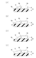
そして、この実施形態のセパレータ30は、少なくとも正極箔11と対峙する無機層32の端部、すなわち、正極活物質層12の端縁付近で露出している内寄部30bから端縁にかけて、正極箔11の一端部11aと対峙するテーパ面33が形成されていることを特徴としている。
The
ただし、生産性や組立性を向上させるため、テーパ面33は、正極箔11と対峙しない端部、すなわち両端部に設けてもよい。いずれにしても、このテーパ面33は、正極活物質層12と重なり合う面32aとなす角度θが鈍角、例えば120°〜150°、好ましくは135°程度とされる。
However, in order to improve productivity and assemblability, the
また、テーパ面33は、図1に示すように、無機層32から連続して基材層31にも設けてもよい。したがって、この基材層31は、尖端形状に形成される。ただし、負極板20の負極活物質層22の端縁から突出している基材層31は、テーパ面でなく、負極活物質層22と重なっている面に連続する平坦面とされ、対峙している2枚の基材層31の表面は、平行になる。
Further, as shown in FIG. 1, the tapered
あるいは、テーパ面33は、図2(a)に示すように、無機層32の内寄部30bから端縁にかけて、無機層32にのみ形成してもよい。このテーパ面33の先端は、無機層32と基材層31との境界部30cに位置し、テーパ面33は基材層31に設けられていない。
Alternatively, the tapered
あるいは、テーパ面33は、図2(b)に示すように無機層32の内寄部30bから無機層32の先端縁の中間部30dにかけて形成してもよい。したがって、このセパレータ30の先端部には、無機層32の先端部と基材層31の先端部とが連続する平坦部が設けられている。
Alternatively, the tapered
また、テーパ面33は、図2(c)に示すように、無機層32の内寄部30bから先端縁30eに向かって、先細りに、かつ、基材層31に食い込むように傾斜し、基材層31も先端側ほど薄肉化されることによって形成してもよい。
Further, as shown in FIG. 2C, the
あるいは、テーパ面33は、図2(d)に示すように、無機層32の内寄部30bから先端縁30fに向かって、ほぼ同一幅で基材層31に食い込むように傾斜し、基材層31が先端側ほど薄肉化されることによって形成してもよい。
Alternatively, as shown in FIG. 2 (d), the tapered
このようなテーパ面33は、基材層31の表面と無機層32の表面とが全幅に亘って平行な状態のセパレータ30の原反が繰り出され、原反の端部がカッタによってカットしたり、ヤスリによって擦られたりすることで、図1、図2(a)(b)のように設けることができ、ロールなどで圧潰されることで、図2(c)(d)のように設けることができる。
Such a
なお、このようにカッタ、ヤスリ、ロールなどで成形されたセパレータ30は、図3(a)に示すように、内寄部30bが角張らずに膨出し、基材層31の先端部31bが突出し、あるいは、図3(b)に示すように、内寄部30bが曲面に形成され、基材層31の先端部31bが曲面状に若干食い込む状態に形成されることがある。セパレータ30の端部30aがこのように形成されても、テーパ面33の機能が損なわれることはない。
As shown in FIG. 3A, the
そして、図1ないし図3に示したようなセパレータ30を正極板10と負極板20とが挟んだ発電要素100を巻回し、発電要素100を電池ケース110内に収納することで電池(二次電池)として使用される。この発電要素100を巻回する際、電池ケース110内に収納する際、あるいは二次電池を車両などに搭載した状態において、二次電池に振動が加えられることにより、あるいは正極板10又は負極板20が膨張収縮することにより、あるいは、電解液が電池ケース110内で移動することにより、セパレータ30の端部が曲げられる。
1 to 3 is wound around the
しかし、このセパレータ30は、正極活物質層12と重なり合う面32aとテーパ面33とのなす角度θが鈍角に形成され、このテーパ面33が正極箔11に衝突することにより、衝撃力がテーパ面33に加えられ、分布荷重が無機層32に作用する状態となるため、無機層32は基材層31から剥離しない。
However, the
また、セパレータ30は、テーパ面33を設けていない基材層31が負極箔21に衝突したとしても、基材層31が多孔質ポリオレフィン膜から形成され、軟質であることから、損傷するなどのダメージが与えられない。したがって、このセパレータ30は、内部短絡によって短絡電流が流れた場合に、局所的に溶融せず、したがって、熱収縮や破膜することを抑制することができる。
Moreover, even if the
なお、本発明は、前記実施の形態に限定することなく、種々変更することができる。例えば、前記実施の形態では、セパレータ30の基材層31が負極板20の負極活物質層22に重なり合い、無機層32が正極板10の正極活物質層12に重なり合い、テーパ面33が正極板11の一端部11aと対峙している場合について説明したが、セパレータ30の基材層31が正極板10の正極活物質層12に重なり合い、無機層32が負極板31の負極活物質層22に重なり合い、テーパ面33が負極箔21の一端部21aと対峙するようにしてもよい。
The present invention can be variously modified without being limited to the above embodiment. For example, in the embodiment, the
また、このセパレータ30を正極板10と負極板20とに挟んだ発電要素100は、円柱状に巻回し、有底円筒状のケース本体内に収納する場合でも使用することができる。また、テーパ面33は、正極箔11と対峙する端部にのみ形成し、正極箔11と対峙しない端部には形成しないようにしてもよい。
The
10……正極板
11……正極箔
11a…一端部
12……正極活物質層
20……負極板
21……負極箔
21a…一端部
22……負極活物質層
30……セパレータ
30a…端部
30b…内寄部
31……基材層
32……無機層
32a…重なり合う面
33……テーパ面
100…発電要素
θ………角度
DESCRIPTION OF
Claims (6)
前記負極板の負極活物質層又は前記正極板の正極活物質層に重ね合わされる基材層と前記正極板の正極活物質層又は前記負極板の負極活物質層に重ね合わされる無機層とが積層され、少なくとも正極箔又は負極箔と対峙する無機層の端部に、正極活物質層又は負極活物質層と重なり合う面に対して鈍角をなすテーパ面が形成されていることを特徴とする電池用のセパレータ。 A battery separator sandwiched between a negative electrode plate in which a negative electrode active material layer is laminated on both sides excluding one end of the negative electrode foil and a positive electrode plate in which a positive electrode active material layer is laminated on both sides excluding one end of the positive electrode foil. There,
A base material layer superimposed on the negative electrode active material layer of the negative electrode plate or the positive electrode active material layer of the positive electrode plate, and an inorganic layer superimposed on the positive electrode active material layer of the positive electrode plate or the negative electrode active material layer of the negative electrode plate. A battery characterized in that a taper surface having an obtuse angle with respect to a surface overlapping with the positive electrode active material layer or the negative electrode active material layer is formed at an end portion of the laminated inorganic layer facing at least the positive electrode foil or the negative electrode foil. Separator for use.
請求項1ないし3のいずれか一項に記載のセパレータが備えられていることを特徴とする電池。 A battery in which a power generation element in which a strip-shaped separator is interposed between a strip-shaped positive electrode plate and a strip-shaped negative electrode plate is housed in a battery case,
A battery comprising the separator according to any one of claims 1 to 3.
均等な厚さの基材層に均等な厚さの無機層を積層した後、無機層の端部をエッジから次第に肉厚になるような斜め向きにカットする、又は斜め向きにプレスすることでテーパ面を形成することを特徴とする電池用のセパレータの製造方法。 It is a manufacturing method of the separator for batteries according to claim 1,
After laminating an inorganic layer with an equal thickness on a base layer with an equal thickness, the end of the inorganic layer is cut obliquely so that it gradually becomes thicker from the edge, or by pressing obliquely A method for producing a separator for a battery, comprising forming a tapered surface.
負極箔と、前記負極箔に積層された負極活物質層とを有し、少なくとも一端部で前記負極活物質層が積層されない負極板と、A negative electrode plate having a negative electrode foil and a negative electrode active material layer laminated on the negative electrode foil, wherein the negative electrode active material layer is not laminated at least at one end;
基材層と、前記基材層に積層された無機層とを有し、前記正極板と前記負極板との間に挟まれるセパレータであって、前記正極活物質層が積層されない部分又は前記負極活物質層が積層されない部分と対峙するセパレータと、を備え、A separator having a base material layer and an inorganic layer laminated on the base material layer and sandwiched between the positive electrode plate and the negative electrode plate, wherein the positive electrode active material layer is not laminated or the negative electrode A separator facing the portion where the active material layer is not laminated,
前記セパレータの前記無機層は、前記正極活物質層及び前記負極活物質層のいずれか一方に対峙し、The inorganic layer of the separator is opposed to either the positive electrode active material layer or the negative electrode active material layer,
前記無機層は、その端部に、前記正極活物質層及び前記負極活物質層のいずれか一方と重なり合う面に対して鈍角をなすテーパ面が形成されているThe inorganic layer has a tapered surface at an end thereof that forms an obtuse angle with respect to a surface that overlaps one of the positive electrode active material layer and the negative electrode active material layer.
電池。battery.
Priority Applications (1)
| Application Number | Priority Date | Filing Date | Title |
|---|---|---|---|
| JP2011061314A JP5692644B2 (en) | 2011-03-18 | 2011-03-18 | Battery, battery separator, and battery separator manufacturing method |
Applications Claiming Priority (1)
| Application Number | Priority Date | Filing Date | Title |
|---|---|---|---|
| JP2011061314A JP5692644B2 (en) | 2011-03-18 | 2011-03-18 | Battery, battery separator, and battery separator manufacturing method |
Publications (3)
| Publication Number | Publication Date |
|---|---|
| JP2012199020A JP2012199020A (en) | 2012-10-18 |
| JP2012199020A5 JP2012199020A5 (en) | 2014-04-17 |
| JP5692644B2 true JP5692644B2 (en) | 2015-04-01 |
Family
ID=47181072
Family Applications (1)
| Application Number | Title | Priority Date | Filing Date |
|---|---|---|---|
| JP2011061314A Active JP5692644B2 (en) | 2011-03-18 | 2011-03-18 | Battery, battery separator, and battery separator manufacturing method |
Country Status (1)
| Country | Link |
|---|---|
| JP (1) | JP5692644B2 (en) |
Families Citing this family (8)
| Publication number | Priority date | Publication date | Assignee | Title |
|---|---|---|---|---|
| US10505229B2 (en) | 2015-02-17 | 2019-12-10 | Gs Yuasa International Ltd. | Energy storage device, energy storage apparatus, and automobile |
| JP2017130269A (en) * | 2016-01-18 | 2017-07-27 | 株式会社Gsユアサ | Power storage element |
| JP6709531B2 (en) * | 2016-01-18 | 2020-06-17 | 株式会社Gsユアサ | Storage element |
| KR101943243B1 (en) * | 2016-04-15 | 2019-01-28 | 스미또모 가가꾸 가부시키가이샤 | Long porous separator, wound body thereof, manufacturing method of wound body and lithium-ion battery |
| WO2017179214A1 (en) | 2016-04-15 | 2017-10-19 | 住友化学株式会社 | Porous separator long body, manufacturing method for same, wound body, and lithium ion battery |
| JP6726398B2 (en) * | 2016-05-10 | 2020-07-22 | 株式会社Gsユアサ | Storage element |
| JP6549175B2 (en) * | 2017-03-30 | 2019-07-24 | 住友化学株式会社 | Porous separator long, wound body thereof, method of manufacturing the same and lithium ion battery |
| CN112751142B (en) * | 2019-10-31 | 2023-05-23 | 美商映能量公司 | Electrochemical cell with integrated ceramic separator |
Family Cites Families (7)
| Publication number | Priority date | Publication date | Assignee | Title |
|---|---|---|---|---|
| EP0898316A4 (en) * | 1997-01-16 | 2005-05-25 | Mitsubishi Paper Mills Ltd | Separator for nonaqueous electrolyte batteries, nonaqueous electrolyte battery using it, and method for manufacturing separator for nonaqueous electrolyte batteries |
| JP4366783B2 (en) * | 1998-11-16 | 2009-11-18 | 株式会社デンソー | Multilayer battery and method of manufacturing electrode thereof |
| JP4144312B2 (en) * | 2002-10-08 | 2008-09-03 | 日産自動車株式会社 | Bipolar battery |
| JP4454340B2 (en) * | 2004-02-23 | 2010-04-21 | パナソニック株式会社 | Lithium ion secondary battery |
| US20060008702A1 (en) * | 2004-06-23 | 2006-01-12 | Sang-Eun Cheon | Secondary battery |
| KR101407772B1 (en) * | 2007-05-25 | 2014-06-18 | 삼성에스디아이 주식회사 | Electorde assembly and secondary battery using the same |
| WO2009103082A2 (en) * | 2008-02-17 | 2009-08-20 | Porous Power Technologies, Llc | Lamination configurations for battery applications using pvdf highly porous film |
-
2011
- 2011-03-18 JP JP2011061314A patent/JP5692644B2/en active Active
Also Published As
| Publication number | Publication date |
|---|---|
| JP2012199020A (en) | 2012-10-18 |
Similar Documents
| Publication | Publication Date | Title |
|---|---|---|
| JP5692644B2 (en) | Battery, battery separator, and battery separator manufacturing method | |
| JP6352870B2 (en) | Electrochemical element and method for producing the same | |
| CA2561749C (en) | Electrochemical cell with two types of separators | |
| US20170098857A1 (en) | Coated stacks for batteries and related manufacturing methods | |
| JP6109467B2 (en) | Separator with heat-resistant insulation layer | |
| JP2009283273A (en) | Separator for electrochemical cell, and battery | |
| WO2017164000A1 (en) | Cylindrical battery | |
| JP5711254B2 (en) | Lithium secondary battery separator and lithium secondary battery including the same | |
| JP5400013B2 (en) | Electrode group and secondary battery using the same | |
| JP6690846B2 (en) | Secondary battery | |
| JP2009272153A (en) | Lithium secondary battery | |
| JP4418243B2 (en) | Jelly roll type electrode assembly and secondary battery employing the same | |
| JP2017120764A (en) | Secondary battery | |
| WO2013051468A1 (en) | Separator with heat resistant insulating layer | |
| WO2017158986A1 (en) | Battery cell | |
| WO2016168715A1 (en) | Coated stacks for batteries and related manufacturing methods | |
| WO2021232312A1 (en) | Battery cell, battery using the battery cell, and electronic device | |
| JP6146231B2 (en) | Secondary battery | |
| JP7332580B2 (en) | secondary battery | |
| JP2017143003A (en) | Power storage device | |
| JP4552414B2 (en) | Film type battery | |
| JP2018181521A (en) | Laminate battery | |
| JPWO2017204064A1 (en) | Secondary battery | |
| JP2017142896A (en) | Secondary battery | |
| JP6531546B2 (en) | Heat-resistant insulating layer-provided separator, and method of manufacturing heat-resistant insulating layer-provided separator |
Legal Events
| Date | Code | Title | Description |
|---|---|---|---|
| RD04 | Notification of resignation of power of attorney |
Free format text: JAPANESE INTERMEDIATE CODE: A7424 Effective date: 20130809 |
|
| A521 | Request for written amendment filed |
Free format text: JAPANESE INTERMEDIATE CODE: A523 Effective date: 20140305 |
|
| A621 | Written request for application examination |
Free format text: JAPANESE INTERMEDIATE CODE: A621 Effective date: 20140305 |
|
| A977 | Report on retrieval |
Free format text: JAPANESE INTERMEDIATE CODE: A971007 Effective date: 20141224 |
|
| TRDD | Decision of grant or rejection written | ||
| A01 | Written decision to grant a patent or to grant a registration (utility model) |
Free format text: JAPANESE INTERMEDIATE CODE: A01 Effective date: 20150109 |
|
| A61 | First payment of annual fees (during grant procedure) |
Free format text: JAPANESE INTERMEDIATE CODE: A61 Effective date: 20150122 |
|
| R150 | Certificate of patent or registration of utility model |
Ref document number: 5692644 Country of ref document: JP Free format text: JAPANESE INTERMEDIATE CODE: R150 |