JP5692335B2 - Seismic isolation device - Google Patents
Seismic isolation device Download PDFInfo
- Publication number
- JP5692335B2 JP5692335B2 JP2013231622A JP2013231622A JP5692335B2 JP 5692335 B2 JP5692335 B2 JP 5692335B2 JP 2013231622 A JP2013231622 A JP 2013231622A JP 2013231622 A JP2013231622 A JP 2013231622A JP 5692335 B2 JP5692335 B2 JP 5692335B2
- Authority
- JP
- Japan
- Prior art keywords
- rigid material
- material layers
- material layer
- seismic isolation
- flange plate
- Prior art date
- Legal status (The legal status is an assumption and is not a legal conclusion. Google has not performed a legal analysis and makes no representation as to the accuracy of the status listed.)
- Active
Links
- 238000002955 isolation Methods 0.000 title claims description 45
- 239000000463 material Substances 0.000 claims description 128
- 229920001971 elastomer Polymers 0.000 claims description 55
- 230000002093 peripheral effect Effects 0.000 claims description 32
- 239000013013 elastic material Substances 0.000 claims description 17
- 239000006096 absorbing agent Substances 0.000 claims description 8
- 229910000831 Steel Inorganic materials 0.000 description 97
- 239000010959 steel Substances 0.000 description 97
- 239000004033 plastic Substances 0.000 description 6
- 238000010586 diagram Methods 0.000 description 3
- 238000013016 damping Methods 0.000 description 2
- 230000001747 exhibiting effect Effects 0.000 description 2
- 230000000087 stabilizing effect Effects 0.000 description 2
- 238000004073 vulcanization Methods 0.000 description 2
- 244000043261 Hevea brasiliensis Species 0.000 description 1
- 229910001128 Sn alloy Inorganic materials 0.000 description 1
- ATJFFYVFTNAWJD-UHFFFAOYSA-N Tin Chemical compound [Sn] ATJFFYVFTNAWJD-UHFFFAOYSA-N 0.000 description 1
- 230000015572 biosynthetic process Effects 0.000 description 1
- 230000006835 compression Effects 0.000 description 1
- 238000007906 compression Methods 0.000 description 1
- 230000007423 decrease Effects 0.000 description 1
- 230000005489 elastic deformation Effects 0.000 description 1
- 238000010030 laminating Methods 0.000 description 1
- 238000004519 manufacturing process Methods 0.000 description 1
- 229920003052 natural elastomer Polymers 0.000 description 1
- 229920001194 natural rubber Polymers 0.000 description 1
- 229920005992 thermoplastic resin Polymers 0.000 description 1
Images


Description
本発明は、橋梁並びにビル、戸建て住宅及び倉庫等の建物等を含む構造物を地震振動から免震する積層ゴム体を具備した免震装置に関する。 The present invention relates to a seismic isolation device including a laminated rubber body that isolates a structure including a bridge and a building such as a building, a detached house, and a warehouse from earthquake vibration.
例えば、特許文献1では、積層ゴム体のうち、建物の上部構造に連結される上部フランジプレートと建物の下部構造に連結される下部フランジプレートとの夫々に近接した部分に発生する歪みの集中を緩和すべく、上部フランジプレートと下部フランジプレートとの間に設けられ、水平方向に延在する複数のゴム板層と複数の鋼板層とを交互に上下方向に積層して形成された積層ゴム体とを備え、前記複数のゴム板層の材質及び厚さを互いに同一とし、それらゴム板層の面積を異ならせることで、それらゴム板層の剛性を前記積層ゴム体の上端及び下端から中央部へ向かうにつれて漸減させた積層ゴム型の免震装置が提案されている。 For example, in Patent Document 1, the concentration of distortion generated in the portions of the laminated rubber body adjacent to the upper flange plate coupled to the upper structure of the building and the lower flange plate coupled to the lower structure of the building is concentrated. Laminated rubber body that is provided between the upper flange plate and the lower flange plate and is formed by alternately laminating a plurality of rubber plate layers extending in the horizontal direction and a plurality of steel plate layers in order to relax The rubber plate layers are made of the same material and thickness, and the areas of the rubber plate layers are made different from each other, whereby the rigidity of the rubber plate layers is increased from the upper end and the lower end of the laminated rubber body to the central portion. A laminated rubber-type seismic isolation device has been proposed that gradually decreases as it goes to.
ところで、積層ゴムを具備した免震装置では、上部構造及び下部構造間の相対的な水平振動による水平方向変形時において、上部フランジプレート及び下部フランジプレートの夫々に近接した積層ゴム体の部分(フィレット部)に応力集中が生じやすく、座屈の原因になり得る前記応力集中を解消する手段が望まれる一方、本来有する免震機能を発揮できることが望まれる。 By the way, in the seismic isolation device having laminated rubber, the portion of the laminated rubber body (fillet) adjacent to the upper flange plate and the lower flange plate at the time of horizontal deformation due to relative horizontal vibration between the upper structure and the lower structure. It is desirable to provide a means for eliminating the stress concentration that can easily cause buckling and cause buckling.
本発明は、前記諸点に鑑みてなされたものであって、その目的とするところは、上部フランジプレート及び下部フランジプレートの夫々に近接した積層ゴム体の部分における応力集中を解消することができる上に本来有する免震機能を発揮することができる免震装置を提供することにある。 The present invention has been made in view of the above-described points, and an object of the present invention is to eliminate stress concentration in the portion of the laminated rubber body adjacent to the upper flange plate and the lower flange plate. An object of the present invention is to provide a seismic isolation device capable of exhibiting the seismic isolation function inherent in the present invention.
本発明の免震装置は、上部構造に連結される上部フランジプレートと、下部構造に連結される下部フランジプレートと、上部フランジプレート及び下部フランジプレート間に設けられていると共に、鉛直方向において交互に積層されたゴム弾性材料層及び剛性材料層を有した積層ゴム体とを具備しており、剛性材料層は、上部フランジプレートに近接配置された少なくとも一つの上部剛性材料層と、下部フランジプレートに近接配置された少なくとも一つの下部剛性材料層と、上部剛性材料層と下部剛性材料層との間に鉛直方向に並んで配された複数の中間部剛性材料層とを具備しており、上部剛性材料層及び下部剛性材料層の少なくとも一方は、当該一方に隣接する複数の中間部剛性材料層のうちの隣接中間部剛性材料層に対して水平方向において長くなるように形成されており、隣接中間部剛性材料層は、鉛直方向において当該隣接中間部剛性材料層よりも中央側に位置する複数の中間部剛性材料層のうちの中央側中間部剛性材料層に対して、水平方向において等しい長さとなるように又は短くなるように形成されている。 The seismic isolation device of the present invention is provided between the upper flange plate connected to the upper structure, the lower flange plate connected to the lower structure, the upper flange plate and the lower flange plate, and alternately in the vertical direction. A laminated rubber elastic material layer and a laminated rubber body having a rigid material layer. The rigid material layer includes at least one upper rigid material layer disposed in proximity to the upper flange plate, and a lower flange plate. At least one lower rigid material layer disposed in close proximity, and a plurality of intermediate rigid material layers arranged in a vertical direction between the upper rigid material layer and the lower rigid material layer. At least one of the material layer and the lower rigid material layer is horizontal with respect to the adjacent intermediate rigid material layer among the plurality of intermediate rigid material layers adjacent to the one The adjacent intermediate portion rigid material layer is formed in the middle intermediate portion of the plurality of intermediate portion rigid material layers positioned on the center side of the adjacent intermediate portion rigid material layer in the vertical direction. The rigid material layer is formed so as to be equal in length or shorter in the horizontal direction.
本発明の免震装置によれば、特に、上部剛性材料層及び下部剛性材料層の少なくとも一方は、当該一方に隣接する複数の中間部剛性材料層のうちの隣接中間部剛性材料層に対して水平方向において長くなるように形成されているために、上部フランジプレート及び下部フランジプレートの夫々に近接した積層ゴム体の部分(フィレット部)における応力集中を解消することができ、隣接中間部剛性材料層は、鉛直方向において当該隣接中間部剛性材料層よりも中央側に位置する複数の中間部剛性材料層のうちの中央側中間部剛性材料層に対して、水平方向において等しい長さとなるように又は短くなるように形成されているために、本来有する繰り返し応力の耐久性を発揮でき、捻れ方向にも免震機能を発揮できる等、装置を大型化させることなく当該装置が本来有する免震機能を発揮し得る。 According to the seismic isolation device of the present invention, in particular, at least one of the upper rigid material layer and the lower rigid material layer is relative to the adjacent intermediate rigid material layer among the plurality of intermediate rigid material layers adjacent to the one. Since it is formed to be long in the horizontal direction, stress concentration in the portion of the laminated rubber body (fillet portion) adjacent to the upper flange plate and the lower flange plate can be eliminated, and the adjacent intermediate portion rigid material The layers are of equal length in the horizontal direction with respect to the central intermediate rigid material layer among the plurality of intermediate rigid material layers positioned more centrally than the adjacent intermediate rigid material layer in the vertical direction. Or, because it is formed to be short, it can demonstrate the durability of the repeated stress that it originally has, and can also exhibit the seismic isolation function in the torsional direction. The device can exhibit a seismic isolation function inherent without.
本発明の免震装置では、剛性材料層は、鉛直方向に夫々互いに並んで配されていると共に水平方向において夫々互いに等しい長さを有している複数の上部剛性材料層を具備していてもよい。 In the seismic isolation device of the present invention, the rigid material layer may include a plurality of upper rigid material layers that are arranged side by side in the vertical direction and that have the same length in the horizontal direction. Good.
本発明の免震装置では、剛性材料層は、鉛直方向に夫々互いに並んで配されている複数の上部剛性材料層を具備しており、複数の上部剛性材料層のうちの上部フランジプレートに最も近接して配置された最上部剛性材料層は、複数の上部剛性材料層のうちの最上部剛性材料層を除く他の上部剛性材料層に対して、水平方向に長くなるように形成されていてもよい。斯かる免震装置によれば、積層ゴム体の水平方向変形時においても複数の上部剛性材料層に塑性変形が生じにくく、これにより、水平方向の剛性を安定させることができ、フィレット部の応力集中に基づく座屈等を生じさせる虞をなくし得る。 In the seismic isolation device of the present invention, the rigid material layer includes a plurality of upper rigid material layers arranged side by side in the vertical direction, and the uppermost flange plate of the plurality of upper rigid material layers is the most. The uppermost rigid material layers arranged in proximity to each other are formed to be longer in the horizontal direction than the other upper rigid material layers except the uppermost rigid material layer of the plurality of upper rigid material layers. Also good. According to such a seismic isolation device, even when the laminated rubber body is deformed in the horizontal direction, plastic deformation is unlikely to occur in the plurality of upper rigid material layers, whereby the horizontal rigidity can be stabilized and the stress of the fillet portion can be stabilized. The possibility of causing buckling or the like based on concentration can be eliminated.
本発明の免震装置では、剛性材料層は、鉛直方向に夫々互いに並んで配されていると共に水平方向において夫々互いに等しい長さを有している複数の下部剛性材料層を具備していてもよい。 In the seismic isolation device of the present invention, the rigid material layer may include a plurality of lower rigid material layers that are arranged side by side in the vertical direction and that have the same length in the horizontal direction. Good.
本発明の免震装置では、剛性材料層は、鉛直方向に夫々互いに並んで配されている複数の下部剛性材料層を具備しており、複数の下部剛性材料層のうちの下部フランジプレートに最も近接して配置された最下部剛性材料層は、複数の下部剛性材料層のうちの最下部剛性材料層を除く他の下部剛性材料層に対して、水平方向に長くなるように形成されていてもよい。斯かる免震装置によれば、積層ゴム体の水平方向変形時においても複数の下部剛性材料層に塑性変形が生じにくく、これにより、水平方向の剛性を安定させることができ、フィレット部の応力集中に基づく座屈等を生じさせる虞をなくし得る。 In the seismic isolation device of the present invention, the rigid material layer includes a plurality of lower rigid material layers arranged side by side in the vertical direction, and the lowermost flange plate of the plurality of lower rigid material layers is the most. The lowermost rigid material layers arranged in proximity to each other are formed to be longer in the horizontal direction than the other lower rigid material layers excluding the lowermost rigid material layer among the plurality of lower rigid material layers. Also good. According to such a seismic isolation device, even when the laminated rubber body is deformed in the horizontal direction, plastic deformation is unlikely to occur in the plurality of lower rigid material layers, thereby stabilizing the rigidity in the horizontal direction and the stress of the fillet portion. The possibility of causing buckling or the like based on concentration can be eliminated.
本発明の免震装置では、積層ゴム体は、剛性材料層の外周縁に加硫接着されていると共にゴム弾性材料層と一体となった筒状の被覆層を更に具備していてもよく、被覆層のうちの前記上部剛性材料層及び下部剛性材料層の少なくとも一方を覆っている被覆部は、当該被覆層のうちの中間部剛性材料層を覆っている被覆部に対して、水平方向に突出していてもよい。 In the seismic isolation device of the present invention, the laminated rubber body may further include a cylindrical covering layer that is vulcanized and bonded to the outer peripheral edge of the rigid material layer and integrated with the rubber elastic material layer, The covering portion covering at least one of the upper rigid material layer and the lower rigid material layer in the covering layer is horizontally oriented with respect to the covering portion covering the intermediate rigid material layer in the covering layer. It may be protruding.
本発明の免震装置では、上部剛性材料層及び下部剛性材料層の少なくとも一方は、複数の中間部剛性材料層の外周縁よりも水平方向外方に位置している円形外周縁を有していてもよい。 In the seismic isolation device of the present invention, at least one of the upper rigid material layer and the lower rigid material layer has a circular outer peripheral edge that is located outward in the horizontal direction from the outer peripheral edges of the plurality of intermediate rigid material layers. May be.
本発明の免震装置では、複数の中間部剛性材料層は円形外周縁を有しており、上部剛性材料層及び下部剛性材料層の少なくとも一方の円形外周縁は、複数の中間部剛性材料層の円形外周縁よりも大径であってもよい。 In the seismic isolation device of the present invention, the plurality of intermediate rigid material layers have a circular outer peripheral edge, and at least one of the circular outer peripheral edges of the upper rigid material layer and the lower rigid material layer has a plurality of intermediate rigid material layers. The diameter may be larger than the circular outer peripheral edge.
本発明の免震装置では、上部剛性材料層及び下部剛性材料層の少なくとも一方は、複数の中間部剛性材料層の外周縁よりも水平方向外方に位置している多角形外周縁を有していてもよい。 In the seismic isolation device of the present invention, at least one of the upper rigid material layer and the lower rigid material layer has a polygonal outer peripheral edge that is positioned outward in the horizontal direction from the outer peripheral edges of the plurality of intermediate rigid material layers. It may be.
本発明の免震装置では、積層ゴム体に設けられた少なくとも一つの柱状孔と、この少なくとも一つの柱状孔に配されている振動エネルギ吸収体とを具備していてもよい。 The seismic isolation device of the present invention may include at least one columnar hole provided in the laminated rubber body and a vibration energy absorber disposed in the at least one columnar hole.
本発明によれば、上部フランジプレート及び下部フランジプレートの夫々に近接した積層ゴム体の部分における応力集中を解消することができる上に本来有する免震機能を発揮することができる免震装置を提供し得る。 According to the present invention, there is provided a seismic isolation device capable of eliminating stress concentration in the portion of the laminated rubber body adjacent to each of the upper flange plate and the lower flange plate and exhibiting the seismic isolation function originally provided. Can do.
次に本発明の実施の形態を、図に示す好ましい例に基づいて更に詳細に説明する。なお、本発明はこれら例に何等限定されないのである。 Next, embodiments of the present invention will be described in more detail based on preferred examples shown in the drawings. The present invention is not limited to these examples.
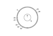
図1から図4において、本例の免震装置1は、建物の上部構造に連結される上部フランジプレート2と、基礎等からなる下部構造に連結される下部フランジプレート3と、上部フランジプレート2及び下部フランジプレート3間に設けられていると共に、鉛直方向Vにおいて交互に積層された天然ゴム又は減衰特性を有する高減衰ゴム等からなる円環状のゴム弾性材料層4及び円環状の剛性材料層5並びに剛性材料層5の外周縁16に加硫接着されていると共にゴム弾性材料層4と一体となった円筒状の被覆層6を有した積層ゴム体7と、積層ゴム体7に設けられた少なくとも一つの柱状孔、本例では一つの柱状孔8と、柱状孔8に配されている振動エネルギ吸収体9と、振動エネルギ吸収体9の下面及び上面において上部フランジプレート2及び下部フランジプレート3に固定されて柱状孔8を閉塞している円盤上の一対の閉塞部材10及び11とを具備している。
1 to 4, the seismic isolation device 1 of the present example includes an
柱状孔8は、積層ゴム体7の内周面12に加えて、上方の閉塞部材10の下面13と下方の閉塞部材11の上面14とによって規定されており、水平方向Hにおいて積層ゴム体7の中央に配されている。振動エネルギ吸収体9は、柱状孔8に密に配された鉛、錫、錫合金又は熱可塑性樹脂製の塑性体、例えば円柱状鉛15からなる。円柱状鉛15は、塑性変形により振動エネルギを吸収する。
The
剛性材料層5は、鉛直方向Vにおいて上部フランジプレート2に近接配置された少なくとも一つの上部剛性材料層としての二枚の円環状の上部剛性鋼板21及び22と、下部フランジプレート3に近接配置された少なくとも一つの下部剛性材料層としての二枚の円環状の下部剛性鋼板23及び24と、上部剛性鋼板21及び22と下部剛性鋼板23及び24との間に鉛直方向Vに並んで配された複数の中間部剛性材料層としての複数の円環状の中間部剛性鋼板25とを具備している。上部剛性鋼板21及び22、下部剛性鋼板23及び24並びに複数の中間部剛性鋼板25の夫々は、同一の軸心Oを有している。
The
上部剛性鋼板21及び22は、鉛直方向Vに夫々互いに並んで配されており、下部剛性鋼板23及び24は、鉛直方向Vに夫々互いに並んで配されており、上部剛性鋼板21及び22、下部剛性鋼板23及び24並びに複数の中間部剛性鋼板25は、鉛直方向Vにおいて夫々互いに等しい間隔をもって配されており、夫々互いに等しい肉厚を有している。このように等しい肉厚を有した鋼板が等間隔をもって配されることにより、ゴム弾性材料層4もまた、夫々互いに等しい肉厚をもって等間隔に配されることになる。
The upper
上部剛性鋼板21及び22のうちの上部フランジプレート2に最も近接して配置された最上部剛性材料層としての上部剛性鋼板21は、上部剛性鋼板22に対して、水平方向Hに長くなるように形成されており、上部剛性鋼板21の円形外周縁31は、上部剛性鋼板22の円形外周縁32よりも大径であって水平方向外方に位置している。上部剛性鋼板21の円形外周縁31及び上部剛性鋼板22の円形外周縁32は、複数の中間部剛性鋼板25の円形外周縁35よりも大径であって水平方向外方に位置している。
Of the upper
下部剛性鋼板23及び24のうちの下部フランジプレート3に最も近接して配置された最下部剛性材料層としての下部剛性鋼板23は、下部剛性鋼板24に対して、水平方向Hに長くなるように形成されており、下部剛性鋼板23の円形外周縁33は、下部剛性鋼板24の円形外周縁34よりも大径であって水平方向外方に位置しており、下部剛性鋼板23の円形外周縁33及び下部剛性鋼板24の円形外周縁34は、複数の中間部剛性鋼板25の円形外周縁35よりも大径であって水平方向外方に位置している。
Of the lower
本例においては、上部剛性鋼板21及び下部剛性鋼板23は夫々互いに同様に形成されており、上部剛性鋼板22及び下部剛性鋼板24は夫々互いに同様に形成されている。以上の剛性材料層5においては、上部剛性鋼板21及び22の夫々は、複数の中間部剛性鋼板25のうちの上部剛性鋼板22に隣接する隣接中間部剛性材料層としての中間部剛性鋼板26に対して水平方向Hにおいて長くなるように形成されており、下部剛性鋼板23及び24の夫々は、複数の中間部剛性鋼板25のうちの下部剛性鋼板24に隣接する隣接中間部剛性材料層としての中間部剛性鋼板27に対して水平方向Hにおいて長くなるように形成されている。
In this example, the upper
複数の中間部剛性鋼板25は、本例では夫々互いに同様に形成されており、これにより、これらは夫々互いに水平方向Hにおいて等しい長さを有することになり、中間部剛性鋼板26及び27は、これらよりも鉛直方向Vにおいて中央側に位置する中央側中間部剛性材料層としての中間部剛性鋼板28に対して、水平方向Hにおいて等しい長さを有することとなる。尚、本例では、複数の中間部剛性鋼板25は夫々互いに同様に形成されているが、この構成に代えて、例えば、中間部剛性鋼板26及び27が、鉛直方向Vにおいて当該中間部剛性鋼板26及び27よりも中央側に位置している中間部剛性鋼板28に対して、水平方向Hにおいて短くなるように形成されていてもよい。
In the present example, the plurality of intermediate
被覆層6は、上部剛性鋼板21及び22を覆っている大径円環状の被覆部41と、下部剛性鋼板23及び24を覆っている大径円環状の被覆部42と、複数の中間部剛性鋼板25を覆っている円環状の被覆部43とを有している。被覆部43の上縁には被覆部41が一体的に連結されており、被覆部43の下縁には被覆部42が一体的に連結されている。被覆部41及び42は、被覆部43に対して、水平方向Hに突出している。
The
免震装置1を製造する場合には、まず、ゴム弾性材料層4と剛性材料層5とを交互に積層して積層体を形成し、その積層体の上面及び下面に上部フランジプレート2及び下部フランジプレート3を配置し、型内における加圧下での加硫接着等によりこれらを相互に固定してなる積層ゴム体7を準備し、その後、円柱状鉛15を柱状孔8に形成すべく、柱状孔8に鉛を圧入する。鉛の圧入は、円柱状鉛15が積層ゴム体7により柱状孔8において隙間なしに拘束されるように、鉛を柱状孔8に油圧ラム等により押し込んで行う。鉛の圧入後、閉塞部材10及び11を取り付ける。尚、型内における加圧下での加硫接着による積層ゴム体7の形成において、剛性弾性材料層5の外周縁16を覆って、円筒状の被覆層6が形成されるようにするとよい。
When manufacturing the seismic isolation device 1, first, a rubber
以上の免震装置1は、地震等が生じて下部構造が水平方向Hに振動すると、図5に示すように、積層ゴム体7が水平方向Hに関して弾性変形し、これにより上部構造を下部構造の水平方向Hの振動に対して免震し、しかも、円柱状鉛15に塑性変形を生じさせて、下部構造の上部構造に対する振動エネルギを吸収して、当該振動を減衰させる。このように積層ゴム体7が水平方向Hに関して弾性変形すると、中間部剛性鋼板28は中間部剛性鋼板27に対して水平方向H1に水平変位し、中間部剛性鋼板27は下部剛性鋼板23及び24に対して水平方向H1に水平変位し、そして、下部剛性鋼板24は下部剛性鋼板23に対して水平方向H1に水平変位する。この際、下部剛性鋼板23及び24は中間部剛性鋼板25、主に中間部剛性鋼板27を支えているので、積層ゴム体7の下部フランジプレート3に近接した圧縮側の部分(フィレット部)に応力集中を生じさせにくくして座屈の虞をなくし得る一方、十分な横断面積を有した複数の中間部剛性鋼板25及びゴム弾性材料層4が交互に積層された部分(中間部)でもって本来有する免震機構を発揮させることができ、しかも、斯かる弾性変形時においても下部剛性鋼板23が下部剛性鋼板24を支えているので、積層ゴム体7の塑性変形及び水平方向の剛性をより安定させることができる。上部剛性鋼板21及び22もまた中間部剛性鋼板26及び28との関係において積層ゴム体7の弾性変形時に下部剛性鋼板23及び24と同様に作用する。
In the seismic isolation device 1 described above, when an earthquake or the like occurs and the lower structure vibrates in the horizontal direction H, the
本例の免震装置1によれば、上部構造に連結される上部フランジプレート2と、下部構造に連結される下部フランジプレート3と、上部フランジプレート2及び下部フランジプレート3間に設けられていると共に、鉛直方向Vにおいて交互に積層されたゴム弾性材料層4及び剛性材料層5を有した積層ゴム体7とを具備しており、剛性材料層5は、上部フランジプレート2に近接配置された少なくとも一つの上部剛性材料層としての上部剛性鋼板21及び22と、下部フランジプレート3に近接配置された少なくとも一つの下部剛性材料層としての下部剛性鋼板23及び24と、上部剛性鋼板21及び22と下部剛性鋼板23及び24との間に鉛直方向Vに並んで配された複数の中間部剛性材料層としての中間部剛性鋼板25とを具備しており、上部剛性鋼板21及び22並びに下部剛性鋼板23及び24は、これらに隣接する複数の中間部剛性鋼板25のうちの隣接中間部剛性材料層としての中間部剛性鋼板26及び27に対して水平方向Hにおいて長くなるように形成されており、中間部剛性鋼板26及び27は、鉛直方向Vにおいて当該中間部剛性鋼板26及び27よりも中央側に位置する複数の中間部剛性鋼板25のうちの中央側中間部剛性材料層としての中間部剛性鋼板28に対して、水平方向Hにおいて等しい長さとなるように又は短くなるように形成されているために、上部フランジプレート2及び下部フランジプレート3の夫々に近接した積層ゴム体7の部分(フィレット部)における応力集中を解消することができ、しかも、本来有する繰り返し応力の耐久性を発揮でき、捻れ方向にも免震機能を発揮できる等、装置を大型化させることなく当該装置が本来有する免震機能を発揮し得る。
According to the seismic isolation device 1 of this example, the
免震装置1によれば、剛性材料層5は、鉛直方向Vに夫々互いに並んで配されている複数の上部剛性鋼板21及び22を具備しており、上部剛性材料層21及び22のうちの上部フランジプレート2に最も近接して配置された最上部剛性材料層としての上部剛性鋼板21は、上部剛性鋼板22に対して、水平方向Hに長くなるように形成されているために、積層ゴム体7の水平方向変形時においても複数の上部剛性鋼板21及び22に塑性変形が生じにくく、これにより、水平方向Hの剛性を安定させることができ、フィレット部の応力集中に基づく座屈等を生じさせる虞をなくし得る。
According to the seismic isolation device 1, the
免震装置1によれば、剛性材料層5は、鉛直方向Vに夫々互いに並んで配されている複数の下部剛性鋼板23及び24を具備しており、下部剛性鋼板23及び24のうちの下部フランジプレート3に最も近接して配置された最下部剛性材料層としての下部剛性鋼板23は、下部剛性鋼板24に対して、水平方向Hに長くなるように形成されているために、積層ゴム体7の水平方向変形時においても複数の下部剛性鋼板23及び24に塑性変形が生じにくく、これにより、水平方向Hの剛性を安定させることができ、フィレット部の応力集中に基づく座屈等を生じさせる虞をなくし得る。
According to the seismic isolation device 1, the
尚、免震装置1の剛性材料層5は、下部剛性鋼板23及び24に代えて、例えば図6に示すように、鉛直方向Vに夫々互いに並んで配されていると共に水平方向Hにおいて夫々互いに等しい長さを有している複数の下部剛性材料層としての下部剛性鋼板53及び54を具備していてもよい。また、剛性材料層5は、前記同様に、上部剛性鋼板21及び22に代えて、鉛直方向Vに夫々互いに並んで配されていると共に水平方向Hにおいて夫々互いに等しい長さを有している複数の上部剛性材料層(図示せず)を具備していてもよい。
In addition, the
上部剛性鋼板21及び22並びに下部剛性鋼板23及び24は、円形外周縁31、32、33及び34を夫々有しているが、これに代えて、例えば図7に示すように、複数の中間部剛性鋼板25の外周縁16よりも水平方向外方に位置している多角形外周縁55を有していてもよい。外周縁16は上述のように円形外周縁であってもよく、また、多角形外周縁であってもよい。この場合、被覆層6は多角筒状であってもよい。
The upper
免震装置1は、本例では振動エネルギ吸収体9を具備しているが、この構成を省いてもよく、この場合、ゴム弾性材料層4及び剛性材料層5の夫々が円板状に形成され、積層ゴム体7が円柱状に形成されてもよい。
The seismic isolation device 1 includes the
1 免震装置
2 上部フランジプレート
3 下部フランジプレート
4 ゴム弾性材料層
5 剛性材料層
6 被覆層
7 積層ゴム体
9 振動エネルギ吸収体
21、22 上部剛性鋼板
23、24、53、54 下部剛性鋼板
25、26、27、28 中間部剛性鋼板
DESCRIPTION OF SYMBOLS 1
Claims (8)
Priority Applications (1)
| Application Number | Priority Date | Filing Date | Title |
|---|---|---|---|
| JP2013231622A JP5692335B2 (en) | 2013-11-07 | 2013-11-07 | Seismic isolation device |
Applications Claiming Priority (1)
| Application Number | Priority Date | Filing Date | Title |
|---|---|---|---|
| JP2013231622A JP5692335B2 (en) | 2013-11-07 | 2013-11-07 | Seismic isolation device |
Related Parent Applications (1)
| Application Number | Title | Priority Date | Filing Date |
|---|---|---|---|
| JP2012193289A Division JP5541329B2 (en) | 2012-09-03 | 2012-09-03 | Seismic isolation device |
Publications (3)
| Publication Number | Publication Date |
|---|---|
| JP2014047926A JP2014047926A (en) | 2014-03-17 |
| JP2014047926A5 JP2014047926A5 (en) | 2014-04-24 |
| JP5692335B2 true JP5692335B2 (en) | 2015-04-01 |
Family
ID=50607794
Family Applications (1)
| Application Number | Title | Priority Date | Filing Date |
|---|---|---|---|
| JP2013231622A Active JP5692335B2 (en) | 2013-11-07 | 2013-11-07 | Seismic isolation device |
Country Status (1)
| Country | Link |
|---|---|
| JP (1) | JP5692335B2 (en) |
Families Citing this family (6)
| Publication number | Priority date | Publication date | Assignee | Title |
|---|---|---|---|---|
| JP2019127994A (en) * | 2018-01-24 | 2019-08-01 | オイレス工業株式会社 | Aseismic base isolation support device |
| JP7182517B2 (en) * | 2019-06-18 | 2022-12-02 | 株式会社ブリヂストン | Seismic isolation device |
| JP7182519B2 (en) * | 2019-06-18 | 2022-12-02 | 株式会社ブリヂストン | Seismic isolation device |
| JP7182518B2 (en) * | 2019-06-18 | 2022-12-02 | 株式会社ブリヂストン | Seismic isolation device |
| JP7404138B2 (en) | 2020-04-06 | 2023-12-25 | 株式会社ブリヂストン | Seismic isolation device |
| JP7390234B2 (en) | 2020-03-30 | 2023-12-01 | 株式会社ブリヂストン | Seismic isolation device |
-
2013
- 2013-11-07 JP JP2013231622A patent/JP5692335B2/en active Active
Also Published As
| Publication number | Publication date |
|---|---|
| JP2014047926A (en) | 2014-03-17 |
Similar Documents
| Publication | Publication Date | Title |
|---|---|---|
| JP5541329B2 (en) | Seismic isolation device | |
| JP5692335B2 (en) | Seismic isolation device | |
| TW200829811A (en) | Seismic isolation device | |
| US20170276204A1 (en) | Vibration damping device for structure | |
| JP3205393U (en) | Seismic isolation device | |
| JP2014047926A5 (en) | ||
| JP4941601B2 (en) | Seismic isolation device | |
| JP6432271B2 (en) | Seismic isolation support device | |
| JP2016223586A (en) | Lamination rubber support | |
| TW201738434A (en) | Seismic isolation bearing for bridge and bridge using the same | |
| JP5703035B2 (en) | Seismic isolation device | |
| JP2019127994A (en) | Aseismic base isolation support device | |
| JP4736715B2 (en) | Seismic isolation device | |
| JP4581832B2 (en) | Composite viscoelastic damper | |
| JP6354303B2 (en) | Laminated rubber bearing device | |
| JP4783627B2 (en) | Laminated rubber bearing | |
| JP6636300B2 (en) | Sliding bearing device | |
| JP2012145197A (en) | Base isolation device | |
| JP4631274B2 (en) | Laminated rubber seismic isolation device mounting structure | |
| JP6611591B2 (en) | Seismic isolation device or seismic isolation member | |
| JP2012052644A (en) | Base isolation device | |
| JP2010180959A (en) | Base isolation device | |
| JP2020204383A (en) | Seismic isolation device | |
| JP5205145B2 (en) | Bearing device | |
| JP2020204384A (en) | Seismic isolation device |
Legal Events
| Date | Code | Title | Description |
|---|---|---|---|
| A521 | Request for written amendment filed |
Free format text: JAPANESE INTERMEDIATE CODE: A523 Effective date: 20140206 |
|
| A621 | Written request for application examination |
Free format text: JAPANESE INTERMEDIATE CODE: A621 Effective date: 20140206 |
|
| A977 | Report on retrieval |
Free format text: JAPANESE INTERMEDIATE CODE: A971007 Effective date: 20141114 |
|
| TRDD | Decision of grant or rejection written | ||
| A01 | Written decision to grant a patent or to grant a registration (utility model) |
Free format text: JAPANESE INTERMEDIATE CODE: A01 Effective date: 20150106 |
|
| A61 | First payment of annual fees (during grant procedure) |
Free format text: JAPANESE INTERMEDIATE CODE: A61 Effective date: 20150119 |
|
| R150 | Certificate of patent or registration of utility model |
Ref document number: 5692335 Country of ref document: JP Free format text: JAPANESE INTERMEDIATE CODE: R150 |
|
| R250 | Receipt of annual fees |
Free format text: JAPANESE INTERMEDIATE CODE: R250 |
|
| R250 | Receipt of annual fees |
Free format text: JAPANESE INTERMEDIATE CODE: R250 |
|
| R250 | Receipt of annual fees |
Free format text: JAPANESE INTERMEDIATE CODE: R250 |
|
| R250 | Receipt of annual fees |
Free format text: JAPANESE INTERMEDIATE CODE: R250 |
|
| R250 | Receipt of annual fees |
Free format text: JAPANESE INTERMEDIATE CODE: R250 |
|
| R250 | Receipt of annual fees |
Free format text: JAPANESE INTERMEDIATE CODE: R250 |
|
| R250 | Receipt of annual fees |
Free format text: JAPANESE INTERMEDIATE CODE: R250 |