JP5688701B2 - Air ring shower - Google Patents
Air ring shower Download PDFInfo
- Publication number
- JP5688701B2 JP5688701B2 JP2012092583A JP2012092583A JP5688701B2 JP 5688701 B2 JP5688701 B2 JP 5688701B2 JP 2012092583 A JP2012092583 A JP 2012092583A JP 2012092583 A JP2012092583 A JP 2012092583A JP 5688701 B2 JP5688701 B2 JP 5688701B2
- Authority
- JP
- Japan
- Prior art keywords
- air
- air ring
- nozzle
- ring
- shower
- Prior art date
- Legal status (The legal status is an assumption and is not a legal conclusion. Google has not performed a legal analysis and makes no representation as to the accuracy of the status listed.)
- Expired - Fee Related
Links
Images


Description
本発明は、人体の塵埃除去に係るクリーンルーム内に設置されるエアーシャワーの利用法に関する。 The present invention relates to a method for using an air shower installed in a clean room for removing dust from a human body.
現在エアーシャワーの利用法としてクリーンルーム内において圧縮空気をエアーノズルより噴射し人体に付着した塵埃を除去する装置が多数考案されている。例えば、特許文献1の場合クリーンルーム内にて人体の上部から下部へと順次に圧縮空気を噴射する方法として、ノズル形状をエアーナイフにより上部から下部へと移動する形態と、エアーノズルを多数備え制御装置により上部から下部へと順次開閉する形態とがある。Currently, as a method of using an air shower, many devices have been devised that eject compressed air from an air nozzle in a clean room to remove dust adhering to a human body. For example, in the case of Patent Document 1, as a method of injecting compressed air sequentially from the upper part to the lower part of the human body in a clean room, a mode in which the nozzle shape is moved from the upper part to the lower part with an air knife, and a number of air nozzles are controlled. There is a form in which the device is opened and closed sequentially from the upper part to the lower part.
本発明はエアーシャワーの利用法として、入浴後及びプール利用後等の濡れた人体に付着した水滴を除去し乾燥を促す装置を提供する事を目的とする。特許文献1においては設備費用が嵩み設置場所も条件が強いられる。又クリーンルームには出入り口が設けられる為圧縮空気の噴射は側方からのみとなる。その為人体に均等に圧縮空気の噴射を受ける為には人体を回転する必要も生ずる。An object of the present invention is to provide an apparatus that removes water droplets attached to a wet human body after bathing or after using a pool as a method of using an air shower and promotes drying. In Patent Document 1 , the equipment cost is increased and the installation location is also constrained. In addition, since the clean room is provided with an entrance, compressed air is injected only from the side. Therefore, it is necessary to rotate the human body so that the human body receives the jet of compressed air evenly.
そこで家庭での設置も考慮しコストパフォーマンスに優れる装置を提供するものでもある。 Therefore, considering the installation at home, we also provide a device with excellent cost performance.
前記目的を達成する為、本発明によるエアーリングシャワーは、エアーリングの内側方向で且つ下方向約30度の噴射角をもつエアーノズルを数箇所に備え、該エアーリングにコンプレッサー又は送風ファン等により圧縮空気を通気管を経由し送り込み、エアーリングの移動に用いる支柱内のレールを最上位置により最下位置へと移動する形態により水滴を除去し乾燥を促す事を可能とする。又通気管内に発熱帯を備え温風を利用する事により乾燥をより促すものとなる。 In order to achieve the above object, the air ring shower according to the present invention includes air nozzles having an injection angle of about 30 degrees in the inner direction of the air ring and a downward direction, and the air ring is provided with a compressor or a blower fan. Compressed air is sent in through a vent pipe, and the rail in the support column used for moving the air ring is moved from the uppermost position to the lowermost position, thereby removing water droplets and promoting drying. In addition, the ventilation pipe is provided with a tropical area, and warm air is used to further promote drying.
エアーノズルにより下方向へ噴射する為人体に付着した水滴を効率よく除去する形態であり、又下降速度を緩やかにする事により乾燥効果をより高めるものである。又下降手段は自重式とする事によりコストパフォーマンスにも優れるものとなる。 This is a mode in which water droplets adhering to the human body are efficiently removed because it is jetted downward by the air nozzle, and the drying effect is further enhanced by slowing the descending speed. Moreover, the descent means is excellent in cost performance by adopting its own weight type.
本発明による人体に付着した水滴除去と乾燥手段は、入浴後の拭き取り作業を簡素化し特に障害者や体の不自由な高齢者には利便性に優れるものである。又、温風や涼風を使い分ける事により、冬期の入浴後は温風により湯冷め防止となり夏期の入浴後は発汗を防ぐ為涼風での利用が効果的である。特にプール利用後の冷えた体の状態での温風利用は非常に快適である。 The water droplet removal and drying means adhering to the human body according to the present invention simplifies the wiping work after bathing, and is particularly convenient for the disabled and disabled elderly. In addition, by using warm air and cool air properly, it is effective to use hot air after bathing in winter to prevent water from being cooled by hot air and to prevent sweating after bathing in summer. The use of hot air in the cold body state after using the pool is very comfortable.
又エアーリングシャワーの利用により温泉旅館等でのバスタオルの利用をなくす事も可能であり、巨大プールにおいては脱衣ケージの利用時間の短縮につながり混雑の解消を促すものである。家庭においても児童の体を親が拭く必要もなく脱衣所の床が濡れる事もなく、特にバスタオルの利用をなくす事が洗濯においても大きな効果を得る事となる。
又、クリーンルームにての利用も可能であり非常に経済的である。
It is also possible to eliminate the use of bath towels at hot spring inns, etc. by using air ring showers, and in a huge pool, it shortens the use time of the dressing cage and promotes the elimination of congestion. Even at home, parents do not need to wipe their children's bodies and the floor of the dressing room does not get wet. In particular, eliminating the use of bath towels can have a great effect on washing.
It can also be used in a clean room and is very economical.
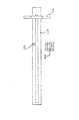
本発明によるエアーリングシャワー本体の構造は送風機4から送られた圧縮空気が通気管3を経由しエアーリング1へ到達しエアーノズル2より噴射される。エアーノズル2による噴射方向はエアーリング1の内側方向であり、且つ下方向へ約30度とする。仮に下方向へ45度の噴射角の場合人体に対する風圧が減少し水滴の飛散効果が低下するものである。
In the structure of the air ring shower main body according to the present invention, the compressed air sent from the
支柱5は主に壁面に取り付け、又送風機4の設置箇所はケース1として隣室、ケース2としてエアーリングシャワーの最上部、ケース3として仮設型に適する支柱背面の最下部が考えられる。
The
エアーリング1の形状は円形状でも可能ではあるが、体形に適応しやすくする為左右対称となる分割可動型(図4参照)の形状とし、エアーリング1を開く事により(図5参照〉大柄な体形でも利用が容易となるサイズへと変更する事ができる。The shape of the air ring 1 can be circular, but in order to make it easier to adapt to the body shape, it is a split movable type (see FIG. 4) that is symmetrical to the left and right, and the air ring 1 is opened (see FIG. 5). Even a simple body shape can be changed to a size that makes it easy to use.
まずエアーリングシャワー本体の第1の形態としてコストパフォーマンスを重視し、家庭用或いは簡易設置型を用途とする簡易タイプの構造を説明する。 First, as a first form of the air ring shower main body, a simple type structure will be described in which a cost performance is emphasized and a household type or a simple installation type is used.
エアーリング1の移動方法においては、支柱内に備えたレールを移動し降下時はエアーリング1に重りを設け自重にて降下する構造である。降下速度はエアーリング1のレール通過部分を摩擦により抵抗を持つ構造とし、その摩擦係数の大きさにより降下速度を設定する事ができる。 The moving method of the air ring 1 is a structure in which a rail provided in the support column is moved and a weight is provided on the air ring 1 and lowered by its own weight when lowered. The descending speed is a structure in which the rail passing portion of the air ring 1 has resistance by friction, and the descending speed can be set by the magnitude of the friction coefficient.
又エアーシリンダーを利用し降下速度を調節する方法もある。その一つとして例をあげると(図11参照)この場合例えばエアーリング1はウェイトを含み約800グラムの自重とし、エアーシリンダー内のウェイト11を約200グラムとする。エアーリング1はエアーシリンダーの下部に設けられた開口部の吸気量により降下速度が設定される為、開口部を可動式の蓋となるスライド板13を移動する事により吸気量を調節する事ができエアーリング1の降下速度は任意の速度に設定可能となる。又手動にてエアーリング1を最上部へ移動する際エアー排気量が少ない為エアーシリンダー内のウェイト11の降下速度が遅くワイヤー12に弛みが生ずる。そこで排気専用の開口部を設け外側より排気弁を用いて塞ぐ事によりウェイト11が降下する際には排気弁14が開き排気量が増大する為ウェイト11は速やかに降下しワイヤー12の弛みが生ずる事もない。There is also a method of adjusting the descent speed using an air cylinder. As an example (see FIG. 11), for example, the air ring 1 includes a weight and has a weight of about 800 grams, and the weight 11 in the air cylinder is about 200 grams. Since the air ring 1 has a descending speed set by the amount of intake air in the opening provided at the lower part of the air cylinder, it is possible to adjust the intake air amount by moving the
次に始動と停止において説明をすると、始動時は支柱に備えたストッパー解除ボタン6を押す事によりストッパー機能が解除されエアーリング1が降下を始める。又ストッパー解除ボタン6の操作と連動した送風機4の作動によりエアーノズル2より圧縮空気が噴射される。稼動修了後エアーリング1が最下位置に到達すると同時にセンサーに依り送風機4が停止する。エアーリングシャワー利用後はエアーリング1を手動にて最上位置まで移動させる事によりストッパー機能が働きエアーリング1が固定される。又エアーリング1のサイズ変更も手動によるものである。この形状は浴室内に設置した場合でも入浴時に支障をきたすものではない。Next, starting and stopping will be described. At the time of starting, the stopper function is released by pushing the
次に通気管3の構造としては特に極度の高圧を要しない為ゴムやビニールのホース状のものでも可能で配管部分は一部露出又は全部露出の方法でもよい。又通気管3を支柱内に備える場合は、支柱の幅を広くし支柱内において通気管3の動きを制御する為の適度な重さを持つリール7(図3)が支柱壁面に備えたレールを利用し上下する構造とする。それによりエアーリング1の上下動によって生ずる通気管3の弛みを防ぐ事ができる。又カール形状のホースを利用する方法もある。Next, as the structure of the vent pipe 3, it is possible to use a rubber or vinyl hose shape because no extremely high pressure is required, and the piping portion may be partially exposed or entirely exposed. In addition, when the vent pipe 3 is provided in the column, the rail 7 is provided with a reel 7 (FIG. 3) having a moderate weight for controlling the movement of the vent tube 3 in the column by widening the column . A structure that moves up and down using Thereby, the slackness of the vent pipe 3 caused by the vertical movement of the air ring 1 can be prevented. There is also a method using a curled hose.
次に第2の形態として電動タイプの場合を説明すると、コストとしては非常にリスクの高いものであるが、体の不自由な方には便利であり病院や療養所において活用できるものである。又多くの利用者がある旅館の大浴場や銭湯、又プール等には利用価値が高いと言える。 Next, the case of the electric type will be described as the second form. Although the cost is very high, it is convenient for people with physical disabilities and can be used in hospitals and nursing homes. In addition, it can be said that the utility value is high in large baths, public baths, and swimming pools of inns with many users.
電動式の場合駆動部と駆動伝達部によりエアーリング1を上下させエアーの吹き出しも降下と同時に作動し降下修了時には自動停止となる。利用後は再び最上位置にて準備状態となる。 In the case of the electric type, the air ring 1 is moved up and down by the drive unit and the drive transmission unit, and the air blowing is also activated at the same time as the descent. After use, it is ready again at the top position.
温風供給方法としては例えば通気管3の末端、つまりエアーリング1の直前近傍の通気管3内に発熱体を2個備え、高温利用時には2個発熱、中温利用時には1個発熱、低温利用時には送風のみとなる構造とする。又は1個の発熱体の発熱量をコントロールする事により幅広く無段階にて温風を供給する事も可能である。 As a hot air supply method, for example, two heating elements are provided at the end of the air pipe 3, that is, in the air pipe 3 near the air ring 1. A structure that only blows air. Alternatively, it is possible to supply a wide range of warm air by controlling the amount of heat generated by a single heating element.
次に分割式エアーリング1について説明すると、利用者の体形に適合する為にはエアーリング1のサイズを変更する必要があり、センサーにより適合させる事も可能ではあるが特に高い精度を要するものではなく、最大と標準の2種類のサイズで対応する方法が適切と思われる。又危険防止の為エアーリング1にセンサーを備え体に触れた場合停止する機能とし、リセットボタンを操作する事により再起動もしくは再び準備状態へと戻る。 Next, the split-type air ring 1 will be explained. In order to adapt to the body shape of the user, it is necessary to change the size of the air ring 1 and it can be adapted by a sensor, but it requires particularly high accuracy. However, it seems appropriate to deal with the maximum and standard two sizes. In order to prevent danger, the air ring 1 is equipped with a sensor so that it stops when it touches the body. By operating the reset button, it is restarted or returned to the ready state.
次にノズル形態及び送風状況について詳しく説明する。本発明によるエアーリングシャワーは水滴を除去すると同時に乾燥の効果もあり、その乾燥効果をより利用度の高い構造とする事ができる。その方法としてノズルを2種類備え、一方は水滴除去専用のエアーノズル2としもう一方を乾燥専用のドライノズル8とする。
Next, the nozzle configuration and the blowing situation will be described in detail. The air ring shower according to the present invention has a drying effect at the same time as removing water droplets, and the drying effect can be made to have a higher utilization structure. As the method, two types of nozzles are provided, one is an
エアーノズル2はコンプレッサーによる圧縮空気を噴射し風圧により水滴を飛散する形態に対し、ドライノズル8はノズルの開口部より送風し風量により乾燥する形態である。ドライノズル8の開口部の大きさは送風される空気量と送風時間により決定され、開口部の形状は丸形に依らず平形も効果的であり、又微小なる開口部を無数に設ける形状も考えられる。エアーの噴射方向及び送風方向はエアーノズル2が下方向約30度に対しドライノズル8は水平方向となる。
The
これらは1本の通気管によって各々のノズルより同時に空気を噴射及び送風し利用目的に適合させる方法である。又、各々のノズルを使い分ける方法としてノズルの吹出口の切り替えを内管(図8)状の開口部を設け、内管をスライドさせる事により開口部を利用ノズルの位置に合わせエアーノズル2とドライノズル8を使い分ける事ができる。しかし風圧の状態により双方の効果が十分得られない場合は、減圧弁等の利用により2本の空気圧の異なる通気管3を利用したり、又送風機を2台備え1台をコンプレッサーによる圧縮空気にてエアーノズル2へ供給し他の1台をファンによりドライノズル8へ送風する手段も考えられる。当然エアーリング1を2本装備し1本はエアーノズル2専用、他の1本はドライノズル8専用とする手段もある(図10参照)。
These are methods in which air is jetted and blown from each nozzle at the same time through a single air pipe so as to suit the purpose of use. In addition, as a method of selectively using each nozzle, the nozzle outlet is switched by providing an opening in the shape of the inner pipe (Fig. 8), and by sliding the inner pipe, the opening is aligned with the position of the nozzle to be used and dry. The
コントロールパネル9についてはそれぞれのスイッチにパイロットランプを備え作動状態を確認できる構造とする。速度とはエアーリング1の降下速度であり乾燥利用時は低速(遅スイッチ)が適切である。 The control panel 9 has a structure in which each switch is provided with a pilot lamp so that the operation state can be confirmed. The speed is the descending speed of the air ring 1, and a low speed (slow switch) is appropriate for drying use.
第3の形態として前述にも触れた簡易設置型について説明すると、構造は第1の形態に準ずるものであるが相違点としては支柱を壁面に取り付けず独立形状の為ベースプレートを用いて設置する事となる。又送風機の設置箇所は支柱背面の下部が安定性においても適切である。その他においては大きく相違するものではない。 When the simple installation type mentioned above is explained as the third form, the structure is similar to the first form, but the difference is that the support is not attached to the wall surface and is installed using the base plate because of the independent shape. It becomes. In addition, the lower part of the back of the column is appropriate for the installation location of the blower. In other respects, there is no significant difference.
最後に頭髪の乾燥について考察を述べると、エアーリング1の降下速度を極度に遅くする方法や一時停止して頭髪の乾燥を十分行う方法、又頭髪専用の大型ノズルを上部に備える方法等が考えられるが、頭髪の乾燥においては風向きや風量・空気温度等個人により繊細さが求められる為本発明においては限定しないものとする。 Finally, to discuss the drying of the hair, there are a method of extremely slowing the descent speed of the air ring 1, a method of sufficiently stopping the hair by temporarily stopping it, and a method of providing a large nozzle exclusively for the hair at the top. However, in the drying of hair, since delicateness is required by individuals such as wind direction, air volume, and air temperature, it is not limited in the present invention.
1 エアーリング
2 エアーノズル
3 通気管
4 送風機
5 支柱
6 ストッパー解除ボタン(簡易タイプのみ)
7 リール
8 ドライノズル
9 コントロールパネル(電動タイプのみ)
10 内管
11 ウェイト
12 ワイヤー
13 スライド板
14 排気弁
1
7
10 Inner pipe 11
Claims (1)
Priority Applications (1)
| Application Number | Priority Date | Filing Date | Title |
|---|---|---|---|
| JP2012092583A JP5688701B2 (en) | 2012-04-16 | 2012-04-16 | Air ring shower |
Applications Claiming Priority (1)
| Application Number | Priority Date | Filing Date | Title |
|---|---|---|---|
| JP2012092583A JP5688701B2 (en) | 2012-04-16 | 2012-04-16 | Air ring shower |
Publications (3)
| Publication Number | Publication Date |
|---|---|
| JP2013221649A JP2013221649A (en) | 2013-10-28 |
| JP2013221649A5 JP2013221649A5 (en) | 2014-05-01 |
| JP5688701B2 true JP5688701B2 (en) | 2015-03-25 |
Family
ID=49592751
Family Applications (1)
| Application Number | Title | Priority Date | Filing Date |
|---|---|---|---|
| JP2012092583A Expired - Fee Related JP5688701B2 (en) | 2012-04-16 | 2012-04-16 | Air ring shower |
Country Status (1)
| Country | Link |
|---|---|
| JP (1) | JP5688701B2 (en) |
Cited By (1)
| Publication number | Priority date | Publication date | Assignee | Title |
|---|---|---|---|---|
| KR102189863B1 (en) * | 2020-05-15 | 2020-12-11 | 신미향 | air towel |
Families Citing this family (3)
| Publication number | Priority date | Publication date | Assignee | Title |
|---|---|---|---|---|
| JP2017086137A (en) * | 2015-11-02 | 2017-05-25 | 三菱電機株式会社 | Clothing maintenance device |
| KR102334895B1 (en) * | 2020-12-03 | 2021-12-03 | 주식회사 하이젠프로 | Air towel with fine dust removal function |
| US11951516B2 (en) * | 2021-01-06 | 2024-04-09 | Hamilton Sundstrand Corporation | Multi-stage cleaning of space suit |
Family Cites Families (6)
| Publication number | Priority date | Publication date | Assignee | Title |
|---|---|---|---|---|
| JPS61101284A (en) * | 1984-10-22 | 1986-05-20 | 株式会社日立製作所 | Air shower device |
| JPH0537196U (en) * | 1991-10-23 | 1993-05-21 | 株式会社イナツクス | Air shower device |
| AUPR726101A0 (en) * | 2001-08-27 | 2001-09-20 | Lim, Dae Song | One stop shower body dryer massage assembly |
| JP2003260107A (en) * | 2002-03-09 | 2003-09-16 | Niiyama Yuji | Body dryer |
| JP4670645B2 (en) * | 2006-01-11 | 2011-04-13 | パナソニック株式会社 | Body drips removal dryer |
| JP3124427U (en) * | 2006-06-06 | 2006-08-17 | ジェイピーシー株式会社 | Air shower equipment |
-
2012
- 2012-04-16 JP JP2012092583A patent/JP5688701B2/en not_active Expired - Fee Related
Cited By (1)
| Publication number | Priority date | Publication date | Assignee | Title |
|---|---|---|---|---|
| KR102189863B1 (en) * | 2020-05-15 | 2020-12-11 | 신미향 | air towel |
Also Published As
| Publication number | Publication date |
|---|---|
| JP2013221649A (en) | 2013-10-28 |
Similar Documents
| Publication | Publication Date | Title |
|---|---|---|
| JP5688701B2 (en) | Air ring shower | |
| US3128161A (en) | After shower body drier | |
| KR20040064689A (en) | Shower recess assembly incorporating body drier | |
| CN105078338A (en) | Multifunctional environment-friendly bath aid | |
| US20180073233A1 (en) | Body cleaner for closestool | |
| CN107550358A (en) | Shower room with sauna function | |
| KR101344421B1 (en) | Device of drying for hair and body | |
| JP2006296749A (en) | Mist generator for bathroom | |
| CN106968461B (en) | A kind of multifunction power bathroom | |
| CN104674901A (en) | Wash basin structure | |
| JP4612364B2 (en) | Mist sauna equipment | |
| JP2006068130A5 (en) | ||
| CN206603022U (en) | A kind of pet cleaning drying integral machine | |
| CN105997404B (en) | A kind of mobile medical health takes up equipment | |
| KR101440683B1 (en) | A pick mugwort appliance | |
| CN204909267U (en) | Multi -functional environmental protection helps machine of bath | |
| US20160169553A1 (en) | Bathroom heater and body dryer | |
| CN107018920A (en) | A kind of domestic cat cleaning device controlled based on mobile phone A PP | |
| JP5324986B2 (en) | Mist sauna equipment | |
| CN107773111A (en) | A kind of thermostatic type modified bathing apparatus | |
| CN106724085B (en) | Multifunction wardrobe | |
| CN2484022Y (en) | Bathroom with hot-air-blasting apparatus | |
| CN209678329U (en) | A kind of bathroom cabinet with bathroom heating device | |
| CN208123509U (en) | A kind of shower faucet structure | |
| KR20150140969A (en) | Perineum dryer |
Legal Events
| Date | Code | Title | Description |
|---|---|---|---|
| A521 | Written amendment |
Free format text: JAPANESE INTERMEDIATE CODE: A523 Effective date: 20140317 |
|
| A621 | Written request for application examination |
Free format text: JAPANESE INTERMEDIATE CODE: A621 Effective date: 20140317 |
|
| A871 | Explanation of circumstances concerning accelerated examination |
Free format text: JAPANESE INTERMEDIATE CODE: A871 Effective date: 20140317 |
|
| A975 | Report on accelerated examination |
Free format text: JAPANESE INTERMEDIATE CODE: A971005 Effective date: 20140409 |
|
| A977 | Report on retrieval |
Free format text: JAPANESE INTERMEDIATE CODE: A971007 Effective date: 20140716 |
|
| A131 | Notification of reasons for refusal |
Free format text: JAPANESE INTERMEDIATE CODE: A131 Effective date: 20140729 |
|
| A521 | Written amendment |
Free format text: JAPANESE INTERMEDIATE CODE: A523 Effective date: 20140917 |
|
| TRDD | Decision of grant or rejection written | ||
| A01 | Written decision to grant a patent or to grant a registration (utility model) |
Free format text: JAPANESE INTERMEDIATE CODE: A01 Effective date: 20150113 |
|
| A61 | First payment of annual fees (during grant procedure) |
Free format text: JAPANESE INTERMEDIATE CODE: A61 Effective date: 20150119 |
|
| R150 | Certificate of patent or registration of utility model |
Ref document number: 5688701 Country of ref document: JP Free format text: JAPANESE INTERMEDIATE CODE: R150 |
|
| R250 | Receipt of annual fees |
Free format text: JAPANESE INTERMEDIATE CODE: R250 |
|
| S531 | Written request for registration of change of domicile |
Free format text: JAPANESE INTERMEDIATE CODE: R313531 |
|
| R350 | Written notification of registration of transfer |
Free format text: JAPANESE INTERMEDIATE CODE: R350 |
|
| R250 | Receipt of annual fees |
Free format text: JAPANESE INTERMEDIATE CODE: R250 |
|
| LAPS | Cancellation because of no payment of annual fees |