JP5687419B2 - Magnetic resonance imaging system - Google Patents
Magnetic resonance imaging system Download PDFInfo
- Publication number
- JP5687419B2 JP5687419B2 JP2009187064A JP2009187064A JP5687419B2 JP 5687419 B2 JP5687419 B2 JP 5687419B2 JP 2009187064 A JP2009187064 A JP 2009187064A JP 2009187064 A JP2009187064 A JP 2009187064A JP 5687419 B2 JP5687419 B2 JP 5687419B2
- Authority
- JP
- Japan
- Prior art keywords
- combination
- imaging
- coil
- coil elements
- magnetic resonance
- Prior art date
- Legal status (The legal status is an assumption and is not a legal conclusion. Google has not performed a legal analysis and makes no representation as to the accuracy of the status listed.)
- Active
Links
- 238000002595 magnetic resonance imaging Methods 0.000 title claims description 39
- 238000003384 imaging method Methods 0.000 claims description 170
- 238000005259 measurement Methods 0.000 claims description 42
- 238000012545 processing Methods 0.000 claims description 26
- 238000005481 NMR spectroscopy Methods 0.000 claims description 16
- 238000011156 evaluation Methods 0.000 claims description 6
- 239000000284 extract Substances 0.000 claims description 5
- 238000000034 method Methods 0.000 description 71
- 230000008569 process Effects 0.000 description 48
- 238000003860 storage Methods 0.000 description 26
- 230000035945 sensitivity Effects 0.000 description 21
- 238000010586 diagram Methods 0.000 description 17
- 238000005457 optimization Methods 0.000 description 16
- 230000010365 information processing Effects 0.000 description 15
- 238000009826 distribution Methods 0.000 description 11
- 238000007689 inspection Methods 0.000 description 10
- 230000005540 biological transmission Effects 0.000 description 9
- 239000011159 matrix material Substances 0.000 description 8
- 230000006870 function Effects 0.000 description 7
- 210000004185 liver Anatomy 0.000 description 6
- 230000015572 biosynthetic process Effects 0.000 description 4
- 230000005284 excitation Effects 0.000 description 4
- 230000003068 static effect Effects 0.000 description 4
- 238000003786 synthesis reaction Methods 0.000 description 4
- 210000001015 abdomen Anatomy 0.000 description 2
- 238000000605 extraction Methods 0.000 description 2
- 238000009434 installation Methods 0.000 description 2
- 238000012423 maintenance Methods 0.000 description 2
- 238000001208 nuclear magnetic resonance pulse sequence Methods 0.000 description 2
- 238000002360 preparation method Methods 0.000 description 2
- 230000000717 retained effect Effects 0.000 description 2
- 238000004904 shortening Methods 0.000 description 2
- 241000894007 species Species 0.000 description 2
- 230000002194 synthesizing effect Effects 0.000 description 2
- 230000004913 activation Effects 0.000 description 1
- 230000008859 change Effects 0.000 description 1
- 238000006243 chemical reaction Methods 0.000 description 1
- 239000000470 constituent Substances 0.000 description 1
- 238000007796 conventional method Methods 0.000 description 1
- 230000003247 decreasing effect Effects 0.000 description 1
- 239000006185 dispersion Substances 0.000 description 1
- 238000002592 echocardiography Methods 0.000 description 1
- 230000005281 excited state Effects 0.000 description 1
- 230000006698 induction Effects 0.000 description 1
- 238000004519 manufacturing process Methods 0.000 description 1
- 230000003287 optical effect Effects 0.000 description 1
- 230000002035 prolonged effect Effects 0.000 description 1
- 230000004044 response Effects 0.000 description 1
- 238000012360 testing method Methods 0.000 description 1
- XLYOFNOQVPJJNP-UHFFFAOYSA-N water Substances O XLYOFNOQVPJJNP-UHFFFAOYSA-N 0.000 description 1
Images


Description
本発明は、磁気共鳴イメージング装置において、計測時間を短縮する技術に関する。特に、パラレルイメージングにおいて、計測時間を短縮する技術に関する。 The present invention relates to a technique for shortening measurement time in a magnetic resonance imaging apparatus. In particular, the present invention relates to a technique for reducing measurement time in parallel imaging.
磁気共鳴イメージング(MRI)装置は、被検体、特に人体の組織を構成する原子核スピンが発生する核磁気共鳴(NMR)信号を計測し、その頭部、腹部、四肢等の形態や機能を2次元的に或いは3次元的に画像化する装置である。NMR信号は、印加される傾斜磁場により位相エンコードおよび周波数エンコードされ、時系列データとして取得される。取得されたNMR信号は、2次元又は3次元フーリエ変換され、画像に再構成される。 A magnetic resonance imaging (MRI) apparatus measures a nuclear magnetic resonance (NMR) signal generated by a nuclear spin constituting a subject, particularly a human tissue, and two-dimensionally describes the shape and function of the head, abdomen, limbs, etc. Or three-dimensional imaging device. The NMR signal is phase-encoded and frequency-encoded by an applied gradient magnetic field and acquired as time series data. The acquired NMR signal is two-dimensional or three-dimensional Fourier transformed and reconstructed into an image.
MRI装置において、計測時間を短縮する技術の一つとして、パラレルイメージング法と呼ばれる手法がある。パラレルイメージング法では、複数の高周波受信コイル(以下、「コイルエレメント」と略記する。)で構成される受信コイル(以下、「マルチプルコイル」と略記する。)を用いて計測空間(以下、「k空間」と略記する)の位相エンコードステップを間引きながらエコーデータの計測を行い、計測時間を短縮する。位相エンコードステップを間引くことによって再構成画像上に発生する折り返しアーチファクト(以下、「折り返し」と略記する。)は、各コイルエレメントの受信感度分布(以下、「感度分布」と略記する。)を用いた行列演算により除去する(例えば、非特許文献1、非特許文献2参照。)。
One technique for shortening measurement time in an MRI apparatus is a technique called a parallel imaging method. In the parallel imaging method, a measurement space (hereinafter referred to as “k”) using a reception coil (hereinafter abbreviated as “multiple coil”) including a plurality of high-frequency reception coils (hereinafter abbreviated as “coil elements”). The echo data is measured while thinning out the phase encoding step (abbreviated as “space”) to shorten the measurement time. A folding artifact (hereinafter abbreviated as “folding”) generated on the reconstructed image by thinning out the phase encoding step uses a reception sensitivity distribution (hereinafter abbreviated as “sensitivity distribution”) of each coil element. (See, for example, Non-Patent
例えば、N個(N≧2)のRF受信コイルを用い、位相エンコードをR倍(R≦N)に間引いて計測することで、撮像時間は1/R倍に短縮する。このような位相エンコードの間引き率Rを倍速数と呼ぶ。パラレルイメージング法では、コイルエレメント数Nを増やすことにより、倍速数Rを大きくでき、より高速な計測が可能になる。また、パラレルイメージング法で得られる画像の画質は、マルチプルコイルの構成に強く依存する。例えば、小径のコイルエレメントを用いることで各コイルエレメントの感度分布の独立性が高まり、画質が向上する。従って、高速性と画質との両立を図るため、一般には、32個以上の小径コイルエレメントを有するマルチプルコイルが使用される。 For example, by using N (N ≧ 2) RF receiving coils and measuring by thinning the phase encoding to R times (R ≦ N), the imaging time is reduced to 1 / R times. Such a phase encoding thinning rate R is called a double speed number. In the parallel imaging method, by increasing the number N of coil elements, the double speed number R can be increased, and higher speed measurement is possible. Further, the image quality of an image obtained by the parallel imaging method strongly depends on the configuration of multiple coils. For example, by using a small-diameter coil element, the independence of the sensitivity distribution of each coil element is increased, and the image quality is improved. Therefore, in order to achieve both high speed and image quality, a multiple coil having 32 or more small-diameter coil elements is generally used.
ところで、計測時に受信するNMR信号はアナログ信号であるため、受信後、AD変換する必要があり、マルチプルコイルを構成するコイルエレメント数と同数のAD変換器(チャネル)を設けることにより、効率よく処理ができる。しかし、MRI装置が備えるチャネル数をマルチプルコイルの数に合わせて増加させると、装置の製造コストの増大を招く。従って、通常、マルチプルコイルを構成するコイルエレメント数より少ないチャネルで処理を行う。このとき、いくつかのコイルエレメントで受信したNMR信号をAD変換器に送信する前に合成する必要がある。撮像条件により、コイルエレメントの最適な配置が異なるため、合成すべきコイルエレメントの組合せも、撮像条件に応じて変更する必要がある(例えば、非特許文献3参照)。 By the way, since the NMR signal received at the time of measurement is an analog signal, it is necessary to perform AD conversion after reception. By providing the same number of AD converters (channels) as the number of coil elements constituting the multiple coil, efficient processing is performed. Can do. However, if the number of channels included in the MRI apparatus is increased in accordance with the number of multiple coils, the manufacturing cost of the apparatus increases. Therefore, processing is normally performed with a smaller number of channels than the number of coil elements constituting the multiple coil. At this time, it is necessary to synthesize NMR signals received by some coil elements before transmitting them to the AD converter. Since the optimal arrangement of the coil elements varies depending on the imaging conditions, the combination of coil elements to be synthesized must also be changed according to the imaging conditions (see, for example, Non-Patent Document 3).
これを実現するため、撮像毎にマルチプルコイルを構成する全コイルエレメントについて、感度計測を行い最適な組み合わせを決定する手法が提案されている(例えば、特許文献1参照。)。また、撮像毎に全コイルエレメントについて低空間分解能画像を取得し、UI(User Interface)に表示されたこれらの画像上で操作者が撮像位置や撮像条件を考慮して、使用するコイルエレメントを選択する手法がある(例えば、特許文献2参照)。 In order to achieve this, a technique has been proposed in which sensitivity measurement is performed on all coil elements constituting a multiple coil for each imaging to determine an optimal combination (for example, see Patent Document 1). In addition, low spatial resolution images are acquired for all coil elements for each imaging, and the operator selects the coil element to be used in consideration of the imaging position and imaging conditions on these images displayed on the UI (User Interface). (For example, refer to Patent Document 2).
特許文献1の手法によれば、撮像毎に、本撮像に先立ち、全コイルエレメントの感度分布を計測する必要がある。このとき、上述のように、コイルエレメント数よりADコンバータ数の方が少ないため、全コイルエレメントの感度分布を得るためには、この感度分布計測を複数回実行する必要がある。従って、全体の計測時間が長くなる。また、特許文献2の手法によれば、最適な組み合わせは、操作者が経験で判断するため、経験によって結果にばらつきが出る。
According to the method of
本発明は、上記事情に鑑みてなされたもので、MRI装置が備えるADコンバータ数が受信コイル(マルチプルコイル)を構成するコイルエレメント数より少ない場合であっても、計測時間を長引かせることなく、安定的に高い品質の画像を得る技術を提供することを目的とする。 The present invention has been made in view of the above circumstances, and even when the number of AD converters included in the MRI apparatus is smaller than the number of coil elements constituting the receiving coil (multiple coil), the measurement time is not prolonged. An object is to provide a technique for stably obtaining a high-quality image.
本発明は、取り得る全ての撮像条件毎の、取り得る全てのコイルエレメント組み合わせに応じた画質スコアを保持するデータベースを、出荷時等に1回作成し、保持する。各検査時は、データベースの中から選択することにより、出力信号を合成する最適なコイルエレメント組合せを自動的に決定する。 In the present invention, a database that stores image quality scores corresponding to all possible coil element combinations for every possible imaging condition is created and held once at the time of shipment or the like. At each inspection, the optimum coil element combination for synthesizing the output signal is automatically determined by selecting from the database.
具体的には、複数のコイルエレメントで構成される受信コイルで受信した核磁気共鳴信号を複数の受信チャネルで処理し、画像化する磁気共鳴イメージング装置であって、検査毎に、当該検査を構成する各撮像の撮像条件の入力を受け付ける受付手段と、前記コイルエレメント数が前記受信チャネル数より多い場合、当該コイルエレメントの中で、合成して1の前記受信チャネルに出力するコイルエレメントの組合せを決定する組合せ決定手段と、前記組合せ決定手段の決定に基づき、前記コイルエレメントで受信した核磁気共鳴信号を合成して前記受信チャネルに出力するよう制御する出力制御手段と、を備え、前記組合せ決定手段は、撮像パラメータと、画質を特定する指標と、に基づいて、前記コイルエレメントの組合せを決定することを特徴とする磁気共鳴イメージング装置を提供する。 Specifically, a magnetic resonance imaging apparatus that processes and images nuclear magnetic resonance signals received by a receiving coil composed of a plurality of coil elements with a plurality of receiving channels, and configures the examination for each examination. Receiving means for receiving an input of imaging conditions for each imaging, and when the number of coil elements is larger than the number of reception channels, a combination of coil elements that are combined and output to one reception channel among the coil elements A combination determining means for determining; and an output control means for controlling to synthesize and output a nuclear magnetic resonance signal received by the coil element to the reception channel based on the determination of the combination determining means, and determining the combination means includes an imaging parameter, and have based the index for identifying the image quality, the, child determine a combination of the coil elements To provide a magnetic resonance imaging apparatus according to claim.
本発明によれば、MRI装置が備えるADコンバータ数がマルチプルコイルを構成するコイルエレメント数より少ない場合であっても、計測時間を長引かせることなく、得られる画像の画質を維持できる。 According to the present invention, even when the number of AD converters included in the MRI apparatus is smaller than the number of coil elements constituting the multiple coil, the image quality of the obtained image can be maintained without prolonging the measurement time.
以下、本発明を適用する実施形態について説明する。以下、本発明の実施形態を説明するための全図において、同一機能を有するものは同一符号を付し、その繰り返しの説明は省略する。 Hereinafter, embodiments to which the present invention is applied will be described. Hereinafter, in all the drawings for explaining the embodiments of the present invention, those having the same function are denoted by the same reference numerals, and repeated explanation thereof is omitted.
まず、本実施形態のMRI装置について説明する。本実施形態のMRI装置は、撮像対象スピン種の密度の空間分布や、励起状態の緩和現象の空間分布を画像化することで、人体頭部、腹部、四肢等の形態または、機能を2次元もしくは3次元的に撮像する。なお、現在臨床で普及している撮像対象スピン種は、被検体の主たる構成物質であるプロトンである。 First, the MRI apparatus of this embodiment will be described. The MRI apparatus of the present embodiment visualizes the form or function of the human head, abdomen, extremities, etc. in two dimensions by imaging the spatial distribution of the density of the spin species to be imaged and the spatial distribution of the relaxation phenomenon of the excited state. Alternatively, three-dimensional imaging is performed. Note that the imaging target spin species that is currently widely used in clinical practice is proton, which is the main constituent of the subject.
図1は、本実施形態のMRI装置100の一例の全体構成を示すブロック図である。本図に示すように、本実施形態のMRI装置100は、NMR現象を利用して被検体1の断層画像を得るもので、静磁場発生系2と、傾斜磁場発生系3と、シーケンサ4と、送信系5と、受信系6と、情報処理系7と、を備える。
FIG. 1 is a block diagram showing an overall configuration of an example of the MRI apparatus 100 of the present embodiment. As shown in the figure, the MRI apparatus 100 of the present embodiment obtains a tomographic image of the
静磁場発生系2は、被検体1の周りの空間にその体軸方向または体軸と直交する方向に均一な静磁場を発生させるもので、被検体1の周りに配置される永久磁石方式または常電導方式あるいは超電導方式の磁場発生手段により構成される。
The static magnetic
傾斜磁場発生系3は、X、Y、Zの3軸方向に巻かれた傾斜磁場コイル31と、それぞれの傾斜磁場コイルを駆動する傾斜磁場電源32とから成り、後述のシ−ケンサ4からの命令に従ってそれぞれのコイルの傾斜磁場電源32を駆動することにより、X、Y、Zの3軸方向の成分を有する傾斜磁場パルスGx,Gy、Gzを被検体1に印加する。例えば、X、Y、Zのいずれかの1方向にスライス方向傾斜磁場パルス(Gs)を印加して被検体1に対するスライス面を設定し、残り2つの方向に位相エンコード方向傾斜磁場パルス(Gp)と周波数エンコード方向傾斜磁場パルス(Gf)を印加して、エコー信号にそれぞれの方向の位置情報をエンコードする。
The gradient magnetic field generation system 3 includes a gradient magnetic field coil 31 wound in three axial directions of X, Y, and Z, and a gradient magnetic field power source 32 that drives each gradient magnetic field coil. By driving the gradient magnetic field power supply 32 of each coil in accordance with the command, gradient magnetic field pulses Gx, Gy, and Gz having components in the three axial directions of X, Y, and Z are applied to the
シーケンサ4は、RFパルスと傾斜磁場パルスとを所定の撮像シーケンスに従って繰り返し印加する制御手段で、情報処理系7の制御で動作し、被検体1の断層画像のデータ収集に必要な種々の命令を送信系5、傾斜磁場発生系3、および受信系6に送る。撮像シーケンスは、RFパルスと傾斜磁場の印加およびエコー信号検出の手順を定めたパルスシーケンスと、これらのタイミング、強度、繰返し時間等を決定する撮像パラメータとにより定まる。なお、パルスシーケンスは、撮像の目的に従って予め作成され、プログラムおよびデータとして情報処理系7内の後述する記憶装置72等に格納される。
The sequencer 4 is a control unit that repeatedly applies an RF pulse and a gradient magnetic field pulse in accordance with a predetermined imaging sequence. The sequencer 4 operates under the control of the
送信系5は、被検体1の生体組織を構成する原子の原子核スピンに核磁気共鳴を起こさせるために高周波磁場(RF)パルスを印加するもので、高周波発振器52と変調器53と高周波増幅器54と送信側の高周波コイル(送信コイル)51とを備える。高周波発振器52から出力された高周波パルスは、シーケンサ4からの指令によるタイミングで変調器53により振幅変調され、高周波増幅器54で増幅された後、被検体1に近接して配置された送信コイル51に供給され、被検体1にRFパルスとして印加される。
The transmission system 5 applies a high-frequency magnetic field (RF) pulse to cause nuclear magnetic resonance to occur in the nuclear spins of the atoms constituting the biological tissue of the subject 1, and includes a high-frequency oscillator 52, a modulator 53, and a high-frequency amplifier 54. And a high-frequency coil (transmission coil) 51 on the transmission side. The high-frequency pulse output from the high-frequency oscillator 52 is amplitude-modulated by the modulator 53 at a timing according to a command from the sequencer 4, amplified by the high-frequency amplifier 54, and then applied to the transmission coil 51 disposed in the vicinity of the
受信系6は、被検体1の生体組織を構成する原子核スピンの核磁気共鳴により放出されるNMR信号(エコー信号)を検出するもので、受信側の高周波コイル(受信コイル)61と増幅器62と直交位相検波器63とA/D変換器64とを備える。送信コイル51から印加されたRFパルスによって誘起される被検体1の応答のエコー信号は、被検体1に近接して配置された受信コイル61で検出され、増幅器62で増幅された後、シーケンサ4からの指令によるタイミングで直交位相検波器63により直交する二系統の信号に分割され、それぞれがA/D変換器64でディジタル量に変換されて、受信信号として情報処理系7に送られる。
The receiving
本実施形態では、受信コイル61は、複数のコイルエレメントからなるマルチプルコイルで構成される。本実施形態の受信系6の詳細な構成を図2に示す。ここでは、直交位相検波器63は省略する。本実施形態の受信コイル61は、N(Nは正の整数)個のコイルエレメント161を備える。増幅器62は、コイルエレメント161と同数の信号増幅器162を備え、A/D変換器64は、M(MはNより小さい正の整数)個のチャネル164を備える。そして、増幅器62とA/D変換器64との間に、エレメント信号合成器163を備える。各コイルエレメントおよび各チャネルには、それぞれを一意に特定するため、エレメント番号n(nは1≦n≦Nを満たす整数)およびチャネル番号m(mは1≦m≦Mを満たす整数)がそれぞれ付与される。
In the present embodiment, the receiving coil 61 is composed of a multiple coil composed of a plurality of coil elements. A detailed configuration of the receiving
エレメント信号合成器163は、N個(コイルエレメント161の数)の入力信号を合成し、M個(チャネル164の数)の出力信号を出力するデバイスである。後述するスイッチングパターンに従って、入力信号を、破棄または合成し、出力する。なお、信号合成時には、合成前の信号に、位相変調を加えるよう構成してもよい。
The
情報処理系7は、操作者から指示に従って、MRI装置100全体の動作の制御、信号処理、画像再構成処理等を行う。本図に示すように、情報処理系7は、CPU71、ROM、RAMなどの記憶装置72、光ディスク、磁気ディスク等の外部記憶装置73と、ディスプレイ等の表示装置74と、マウス、トラックボール、キーボード等の入力装置75とを備える。受信系6から受信信号が入力されると、CPU71が信号処理、画像再構成処理を実行し、その結果として得られる被検体1の断層画像を表示装置74に表示すると共に、記憶装置72または外部記憶装置73に記録する。また、情報処理系7は、予め記憶装置72等に格納されている撮像シーケンスに従って、シーケンサ4に指令を与える。
The
本実施形態の情報処理系7は、さらに、被検体1が配置され、撮像条件が入力される毎に、入力された撮像条件に基づき、コイルエレメント161の有効無効を判別し、有効と判別されたコイルエレメント161の中で、その出力信号をエレメント信号合成器163で合成する組合せを決定し、決定に応じて出力信号を合成し各チャネル164に振り分けるスイッチングパターンを決定する。以下、本処理を、各コイルエレメント161の中で、その出力信号を合成する最適な組合せを決定するものであるため、エレメント組合せ最適化処理と呼ぶ。
The
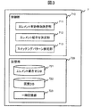
上記エレメント組合せ最適化処理を実現する本実施形態の情報処理系7の機能構成について説明する。図3は、本実施形態の情報処理系7の、エレメント組合せ最適化処理を実現する機能を抽出した機能ブロック図である。本図に示すように、本実施形態の情報処理系7の最適化処理部700は、制御部710と記憶部720とを備える。
A functional configuration of the
制御部710は、受信コイル61を構成する各コイルエレメント161について、検査で実行する全撮像の撮像領域内で所定以上の感度を有する有効コイルエレメントであるか、それ以外の無効コイルエレメントであるかを決定するエレメント有効無効決定部711と、有効コイルエレメントと決定されたコイルエレメント161の数が、チャネル164数以上の場合、その出力信号を、同じチャネル164で処理するコイルエレメント161の組み合わせを決定するエレメント組合せ決定部712と、決定した組合せに従って、各コイルエレメント161からの信号を合成し、各チャネル164に出力するようエレメント信号合成器163を制御するスイッチングパターンを設定するスイッチングパターン設定部713と、を備える。
Whether the
記憶部720は、エレメント組合せ最適化処理を行うために必要な各種の情報を記憶する。本実施形態では、出力を合成するコイルエレメント161の、取り得る全ての組合せ(エレメント組合せ)を保持するエレメント組合せデータベース(エレメント組合せDB)721と、撮像条件およびエレメント組合せ毎の画像の質を示す指標(画質スコアと呼ぶ。)を保持する画質データベース(画質DB)722と、エレメント組合せ最適化処理中に生成される情報を記憶する一時記憶部723と、を備える。一時記憶部723には、例えば、後述する、エレメント有効無効テーブル724、最適エレメント組合せ725、スイッチングパターン726等が保持される。
The
なお、撮像毎の撮像条件は、入力装置75を介して操作者から入力される。入力された撮像条件は、一時記憶部723に格納される。
The imaging conditions for each imaging are input from the operator via the input device 75. The input imaging conditions are stored in the
情報処理系7の制御部710が実現する各機能は、記憶装置72または外部記憶装置73に格納されたプログラムを、CPU71がメモリ(不図示)にロードすることにより実現される。また、記憶部720は、記憶装置72または外部記憶装置73により実現される。
Each function realized by the
次に、上記各機能を用いた本実施形態の最適化処理部700によるエレメント組合せ最適化処理の手順について説明する。図4は、本実施形態のエレメント組合せ最適化処理の処理フローである。ここでは、検査は、1以上の撮像からなるものとする。 Next, the procedure of element combination optimization processing by the optimization processing unit 700 of the present embodiment using the above functions will be described. FIG. 4 is a process flow of the element combination optimization process of the present embodiment. Here, the inspection is made up of one or more images.
このエレメント組合せ最適化処理は、被検体1および受信コイル61がセッティングされ、検査を構成する各撮像について、それぞれ撮像条件が入力され、検査開始の指示を受け付けると、検査を構成する全撮像に先立ち、実行される。ここでは、コイルエレメント161の数をN、チャネル164の数をM(M、Nは、N>M≧2を満たす正の整数)とする。
In this element combination optimization process, when the
被検体1および受信コイル61がセッティングされ、検査開始の指示を受け付けると、エレメント有効無効決定部711は、エレメント有効無効決定処理を実行し、各コイルエレメントの有効無効を決定する(ステップS201)。エレメント有効無効決定処理の詳細は後述する。
When the subject 1 and the receiving coil 61 are set and an instruction to start examination is received, the element validity /
次に、エレメント組合せ決定部712は、ステップS201で有効とされたコイルエレメント161の数Ne(Neは自然数)をカウントし(ステップS202)、チャネル164の数Mとの大小を判別する(ステップS203)。有効なコイルエレメント161の数Neがチャネル164の数M以下である場合、エレメント組合せ決定部712は、有効とされたコイルエレメント161からの出力を、そのまま各チャネル164に割り当て(ステップS211)、エレメント組合せ最適化処理を終了する。
Next, the element
一方、有効なコイルエレメント161の数Neがチャネル164の数Mより大きい場合、エレメント組合せ決定部712は、エレメント信号合成器163で合成する最適なコイルエレメント161の組み合わせを最適エレメント組合せとして決定するエレメント組合せ決定処理を実行する(ステップS204)。エレメント組合せ決定処理の詳細は後述する。
On the other hand, when the number Ne of
エレメント信号合成器163で出力信号を合成するエレメントの組み合わせが決定したら、スイッチングパターン設定部713は、決定に従って、信号受信時に、当該コイルエレメント161からの出力信号を合成する指示であるスイッチングパターンを生成するスイッチングパターン生成処理を行い、スイッチングパターンとして一時記憶部723に保持する(ステップS205)。そして、エレメント組合せ最適化処理を終了する。
When the
以下、各処理の詳細を説明する。まず、ステップS201のエレメント有効無効決定部711によるエレメント有効無効決定処理について説明する。本実施形態のエレメント抽出処理では、検査で実行される各撮像の撮像領域全てを包含する領域の中で、所定以上の感度を有するコイルエレメント161を、有効なコイルエレメントと判別する。そして、一時記憶部723に、図5に示すエレメント有効無効テーブル724を完成させる。エレメント有効無効テーブル724には、エレメント有効無効決定部711により決定された各コイルエレメントの有効無効を示す有効無効フラグが格納される。
Details of each process will be described below. First, the element validity / invalidity determining process by the element validity /
図6は、本実施形態のエレメント有効無効決定処理の処理フローである。また、図7は、エレメント有効無効決定処理の具体例を説明するための図である。図7(a)は、マルチスライス撮像を1回行う計測の場合であって、図7(b)は、マルチスライス撮像を、異なる撮像領域について1回ずつ計2回行う計測の場合を示す。 FIG. 6 is a process flow of the element validity / invalidity determination process of the present embodiment. FIG. 7 is a diagram for explaining a specific example of the element valid / invalid determination process. FIG. 7A shows the case of measurement in which multi-slice imaging is performed once, and FIG. 7B shows the case of measurement in which multi-slice imaging is performed twice for each different imaging region.
エレメント有効無効決定部711は、エレメント有効無効決定処理開始の指示を受け付けると、設置された受信コイル61のコイルエレメント数Nを抽出する(ステップS301)。なお、このエレメント数Nは、コイル認識番号、撮像条件として入力されるコイル情報等から抽出する。
When the element validity /
次に、エレメント有効無効決定部711は、検査を構成する各撮像の撮像条件に基づき、各コイルエレメント161の有効無効を判別する判別領域を設定する(ステップS302)。上述のように、本実施形態の検査では、1以上の撮像が実行され、撮像毎に異なる断面および視野(FOV; Field Of View)が撮像条件として設定される。ここでは、これらの入力された撮像条件から、各撮像の撮像領域を決定し、決定した全撮像領域を含む領域を判別領域として設定する。例えば、図7(a)の例では、マルチスライス撮像(スライス数6枚)の撮像領域901を含む領域902を判別領域と設定する。また、図7(b)の例では、2回のマルチスライス撮像(共にスライス数6枚)の、それぞれの撮像領域903および904の両方を含む領域905を、判別領域と設定する。
Next, the element validity /
次に、エレメント有効無効決定部711は、カウンタnに1を設定する(ステップS303)。そして、エレメント番号がnであるコイルエレメント161(以下、コイルエレメントnと呼ぶ。)のみを信号受信可能な状態(アクティブ化)とする(ステップS304)。このとき、コイルエレメントn以外のコイルエレメントは、信号受信不可能な状態とする。
Next, the element validity /
そして、エレメント有効無効決定部711は、励起RFパルスを照射しない状態で、コイルエレメントnで信号を受信し、コイルエレメントnのノイズレベルを示すノイズレベル信号を計測する(ステップS305)。続いて、上記ステップS302で設定した判別領域を空間選択する励起RFパルスを照射し(ステップS306)、エコー信号を計測する(ステップS307)。
Then, the element validity /
そして、エレメント有効無効決定部711は、ステップS305で計測したノイズレベル信号とステップS307で計測したエコー信号とを比較する(ステップS308)。ここで、両信号は、複素数で表される複素信号であるため、それぞれ絶対値化し、各信号の最大値または平均値を比較する。比較は、両者の値の差分を取ることによって行う。比較した結果、両者の値の差が予め定められた値以上の場合は、有効とし、そうでない場合は無効と判別する(ステップS309)。これは、ノイズレベルとエコー信号強度との差が所定以上ある場合は、当該コイルエレメントは本計測の計測領域に対して、受信感度を有すると判断できるためである。そして、エレメント有効無効テーブル724に、判別を行ったコイルエレメントnの判別結果として有効無効フラグを追記する(ステップS310)。ここでは、例えば、有効無効フラグとして、有効と判別されたコイルエレメントには1を、無効と判別されたコイルエレメントには0を記録する。
Then, the element validity /
その後、エレメント有効無効決定部711は、全てのコイルエレメントについて、有効、無効の判別を終えたか判断する(ステップS311)。ここでは、カウンタnがNと等しくなったか否かで判別する。全てのコイルエレメントについて判別を終えている場合は、処理を終了する。一方、未処理のコイルエレメントがある場合は、カウンタnを1インクリメントし(ステップS312)、ステップS304に移行し、処理を継続する。
Thereafter, the element validity /
なお、上記ステップS307で計測するエコー信号は、FID(Free Induction Decay:自由誘導減衰)信号、照射する励起RFパルスについで再収束RFパルスを印加することにより発生させるスピンエコー型信号、および、照射する励起RFパルスについで再収束傾斜磁場を印加することにより発生させるグラディエントエコー信号のいずれであってもよい。 Note that the echo signal measured in step S307 includes a FID (Free Induction Decay) signal, a spin echo type signal generated by applying a refocusing RF pulse following an excitation RF pulse to be irradiated, and an irradiation signal. Any of gradient echo signals generated by applying a refocusing gradient magnetic field to the excitation RF pulse to be performed may be used.
以上の処理により、本実施形態のエレメント有効無効決定部711は、エレメント有効無効テーブル724を完成させる。
Through the above processing, the element validity /
次に、ステップS204の、エレメント組合せ決定部712によるエレメント組合せ決定処理について説明する。本実施形態のエレメント組合せ決定部712は、有効なコイルエレメント161の数が、チャネル数164以上である場合、その出力信号を合成し、一のチャネル164で処理するコイルエレメント161の組み合わせを決定する。決定には、撮像条件毎にコイルエレメント161の組み合わせ毎の画質スコアを保持する、画質DB722を用いる。
Next, the element combination determination process by the element
エレメント組合せ決定処理の説明に先立ち、画質DB722について説明する。画質DB722は、所定の撮像パラメータ値で所定のコイルエレメント組合せで撮像した場合の画質スコアを保持する。画質DB722は、予め作成され、記憶部720に保持される。図8は、本実施形態の画質DB722の一例を説明するための図である。
Prior to the description of the element combination determination process, the
本図に示すように、本実施形態の画質DB722には、撮像パラメータ722aおよびコイルエレメントの組み合わせを特定する情報である組合せID722bと、これらにより決定する画質スコア722cとが対応づけられ、1レコードとして保持される。
As shown in this figure, in the
ここで、撮像パラメータ722aとして保持される撮像パラメータの種は、撮像結果、すなわち、画質スコア722cに影響を与えるものが選択される。選択される撮像パラメータ種は、例えば、撮像断面を特定する断面情報、位相エンコード方向を特定する位相方向、FOV、パラレルイメージング倍速数、マルチスライス撮像の場合、スライス方向、などである。各撮像パラメータの値を、所定の範囲で、所定の増分で変化させ、登録する。撮像パラメータの値を変化させる範囲(定義域)および増分は、MRI装置100のスペック、臨床使用範囲、画質DB722のレコード数と記憶領域との関係などにより定められる。
Here, the type of the imaging parameter held as the
本図においては、断面情報と位相方向とFOVと例示する。断面情報は、断面中心の3次元位置および3つのオブリーク角の計6つのパラメータからなる。また、位相方向としては、断面情報で決定した面内の横方向(Horizontal)および縦方向(vertical)の2種の値が格納される。 In this figure, cross-sectional information, phase direction, and FOV are illustrated. The cross-section information is composed of a total of six parameters including a three-dimensional position of the cross-section center and three oblique angles. In addition, as the phase direction, two kinds of values, that is, a horizontal direction (Horizontal) and a vertical direction (vertical) in the plane determined by the cross-sectional information are stored.
組合せID722bは、コイルエレメント161を合成する必要がある場合の、合成対象のコイルエレメント161の組合せを特定する情報である。組合せID722bとして、予め作成された発生する可能性のある全組み合せを保持するエレメント組合せDB721の組合せIDが格納される。
The
ここで、エレメント組合せDB721について説明する。本実施形態では、エレメント組合せDB721には、無効なコイルエレメント161の組み合わせ毎の、残りの有効なコイルエレメント161に関する、その出力を合成するコイルエレメント161の組合せ(エレメント組合せ)が格納される。無効なコイルエレメント161数は、有効なコイルエレメント161の数がチャネル164の数より多くなる範囲の値である。
Here, the
図9はエレメント組合せDB721を説明するための図である。本図に示すように、エレメント組合せDB721には、各コイルエレメント161の無効または組合せを特定する無効組合せ情報721bが、各無効組合せ情報721bを一意に特定する組合せID721aに対応づけて保持される。無効組合せ情報721bとして、コイルエレメント161が無効の場合は、無効を示す情報(図では、Disableと示す。)、有効の場合は、組み合わせるコイルエレメント161毎を1のグループとし、各グループを特定する情報(図ではGrm;mは1≦m≦Mを満たす自然数と示す。)が保持される。
FIG. 9 is a diagram for explaining the
組合せのグループ数は、チャネル数M以下1以上の任意の数である。また、無効なコイルエレメントの数は、N−M−1個以下の任意の数である。保持される最大レコード数Rは、以下の式(1)で表される。

例えば、コイルエレメント数Nが6で、チャネル数Mが3の場合、無効コイルエレメント数Nnとして取り得る値は、1または2である。また、組合せのグループ数は、3、2、1のいずれかである。具体的には、Nnが1の場合、無効なコイルエレメントの選択は6通りである。残りの5つのコイルエレメント161を、3以下のグループに分類する際の場合の数は、1+(35−3)/3!=41通りである。従って、Nnが1の場合、組合せは、41×6=246通りとなる。Nnが2の場合、無効なコイルエレメントの選択は、6×5/2!=15通りである。残りの4つのコイルエレメントを3以下のグループに分類する。この場合の数は、1+(34−3)/3!=14通りである。従って、Nnが2の場合、組合せは、15×14=210通りとなる。従って、コイルエレメント数Nが6で、チャネル数Mが3の場合、246+210=456通りの組合せを取り得、同数のレコードが保持される。
For example, when the number of coil elements N is 6 and the number of channels M is 3, the value that can be taken as the number of invalid coil elements Nn is 1 or 2. Further, the number of groups of combinations is either 3, 2, or 1. Specifically, when Nn is 1, there are six invalid coil element selections. When the remaining five
例えば、各コイルエレメント161について、(N−M−1)個から0個までの無効なコイルエレメント161の全組み合わせについて、それぞれ、残りの有効なコイルエレメント161の、可能な全組み合わせ(グループ化)を抽出し、格納する。なお、エレメント組合せDB721は、MRI装置100の出荷時、据付時等に、受信コイル61毎に作成する。
For example, for each
また、画質スコア722cとして保持される値は、以下の式(2)に従って算出されるスコア(Score)の値である。
Score=10−a(g−1) (2)
ここで、gはジオメトリックファクタであり、パラレルイメージング撮像条件下における各コイルエレメント161の受信感度の適合度を示す値である。aは0より大きい実数であって、予め定められた定数とする。一般に、5〜10程度が用いられる。なお、ジオメトリックファクタgは、以下の式(3)により計算される。
![]()
Score = 10−a (g−1) (2)
Here, g is a geometric factor, which is a value indicating the adaptability of the reception sensitivity of each
![]()
また、着目位置(x0、y0、z0)におけるチャンネル感度行列S(x0、y0、z0)は、以下の式(4)で表される。
式(3)に示すように、使用するコイルエレメント161の組合せおよび/およびまたは上記撮影パラメータが変化すると、チャンネル感度行列Sが変化し、ジオメトリックファクタgの値が変化する。従って、式(2)で計算されるスコアも変化する。
As shown in Expression (3), when the combination of
以上説明した画質DB722の作成手順を説明する。図10は、画質DB722の作成手順を説明するための図である。ここでは、説明を簡単にするため、選択される撮像パラメータが3種(それぞれp1、p2、p3と呼び、その値をp1v、p2v、p3vとする)の場合を例にあげて説明する。各撮像パラメータの定義域をp1start≦p1v≦p1end、p2start≦p2v≦p2end、p3start≦p3v≦p3end、増分をΔp1、Δp2、Δp3とする。なお、上記位相方向のように、取り得る値が離散的で、予め特定される場合は、その値のみを採用する。
A procedure for creating the
受信コイル61がMRI装置100にセットされた後、操作者の作成開始の指示をトリガとして作成処理は開始される。まず、エレメント組合せデータベース721を参照し、エレメント組合せの総数Q(Qは自然数)を抽出する(ステップS401)。そして、画質DB722の撮像パラメータ722aとして保持する撮像パラメータ、および各々の撮像パラメータの定義域と増分との入力を受け付け、保持する(ステップS402)。
After the reception coil 61 is set in the MRI apparatus 100, the creation process is started with an operator's creation start instruction as a trigger. First, referring to the
次に、従来の手法で、全コイルエレメント161の感度分布を計測する(ステップS403)。コイルエレメント161の数Nが、チャネル164数Mより大きい場合、全てのコイルエレメント161のデータを処理できるまで、複数回感度計測を行う。計測対象として水や脂肪を含むファントムを用いて行う。なお、ボランティアの被検体を用いて計測してもよい。なお、以上のステップS401からS403の順序は問わない。これらの処理がこの時点までに行われればよい。
Next, the sensitivity distribution of all the
パラメータp1の値p1vとして、初期値p1startを設定する(ステップS404)。次に、パラメータp2の値p2vとして、初期値p2startを設定する(ステップS405)。次に、パラメータp3の値p3vとして、初期値p3startを設定する(ステップS406)。次に、組合せIDをカウントするカウンタqに1を設定する(ステップS407)。 An initial value p1 start is set as the value p1v of the parameter p1 (step S404). Next, an initial value p2 start is set as the value p2v of the parameter p2 (step S405). Next, an initial value p3 start is set as the value p3v of the parameter p3 (step S406). Next, 1 is set to the counter q that counts the combination ID (step S407).
組合せID721aがqであるレコードをエレメント組合せデータベース721から抽出し(ステップS408)、現時点での各撮像パラメータの値p1v、p2v、p3vおよび抽出した組合せIDで特定される組み合わせの場合の画質スコア722cを上記式(2)に従って、算出する(ステップS409)。
A record whose
算出結果を、現時点での各撮像パラメータの値p1v、p2v、p3vおよび組合せIDqに対応付けて、組合せ画質データベース722の画質スコア722cとして保持する(ステップS410)。そして、全組合せID721aに対して処理を行ったか否かを判別する(ステップS411)。未処理のレコードがある場合は、カウンタqを1インクリメントし(ステップS412)、ステップS408に戻る。 The calculation results, the values of the imaging parameters at the moment P1V, p2v, in association with p3v and combinations I Dq, held as the image quality score 722c combination quality database 722 (step S410). And it is discriminate | determined whether the process was performed with respect to all the combination ID721a (step S411). If there is an unprocessed record, the counter q is incremented by 1 (step S412), and the process returns to step S408.
一方、全てのレコードについて処理を終えたと判別された場合は、撮像パラメータp3の値p3vをΔp3だけ増加させ(ステップS413)、増加後の撮像パラメータp3vの値が定義域の最大値p3endを超えたか否かを判別する(ステップS414)。超えていないと判別された場合は、ステップS407に戻る。 On the other hand, if it is determined that the processing has been completed for all records, the value p3v of the imaging parameter p3 is increased by Δp3 (step S413), and the value of the imaging parameter p3v after the increase exceeds the maximum value p3 end of the domain It is determined whether or not (step S414). If it is determined that it has not exceeded, the process returns to step S407.
一方、ステップS414において、超えていると判別された場合は、撮像パラメータp2の値p2vをΔp2だけ増加させ(ステップS415)、増加後の撮像パラメータの値p2vが定義域の最大値p2endを超えたか否かを判別する(ステップS416)。超えていないと判別された場合は、ステップS406に戻る。 On the other hand, if it is determined in step S414 that it has exceeded, the value p2v of the imaging parameter p2 is increased by Δp2 (step S415), and the increased imaging parameter value p2v exceeds the maximum value p2 end of the domain. It is determined whether or not (step S416). If it is determined that it has not exceeded, the process returns to step S406.
一方、ステップS416において、超えていると判別された場合は、撮像パラメータp1の値p1vをΔp1だけ増加させ(ステップS417)、増加後の撮像パラメータの値p1vが定義域の最大値p1endを超えたか否かを判別する(ステップS418)。超えていないと判別された場合は、ステップS405に戻る。 On the other hand, if it is determined in step S416 that it has exceeded, the value p1v of the imaging parameter p1 is increased by Δp1 (step S417), and the increased imaging parameter value p1v exceeds the maximum value p1 end of the domain. It is determined whether or not (step S418). If it is determined that it has not exceeded, the process returns to step S405.
一方、ステップS418において、超えていると判別された場合は、処理を終了する。以上の手順により、本実施形態の組合せ画質DB722を作成する。
On the other hand, if it is determined in step S418 that the number has exceeded, the process ends. The combined
なお、画質DB722は、受信コイル61毎に、MRI装置100の出荷時、据付時といった検査開始前の所定の時期に作成される。メンテナンス時に再度作成し、更新するよう構成してもよい。また、ここでは、考慮する撮像パラメータ数が3つである場合を例にあげて説明しているが、撮像パラメータ数はこれに限られない。撮像パラメータ数に応じて、組合せ画質データベース722作成処理中の多重ループの段数を増減させる。また、画質DB722およびエレメント組合せDB721は、制御部710が作成してもよいし、外部の他の装置で作成し、記憶部720に格納するよう構成してもよい。
Note that the
ステップS204のエレメント組合せ決定部712によるエレメント組合せ決定処理に戻り、その手順を説明する。図11は、本実施形態のエレメント組合せ決定処理の処理フローである。
Returning to the element combination determination process by the element
エレメントの有効無効の決定を終えると、エレメント組合せ決定部712は、まず、画質DB722から、コイルエレメントの有効無効の組合せが、ステップS201で決定したエレメントの有効無効の組合せに合致し、かつ、撮像パラメータ722aが検査で行われる各撮像条件に合致するレコードを抽出する。
Upon completion of the determination of effective disabling element, the element
ここでは、エレメント組合せ決定部712は、エレメント組合せDB721を参照し、エレメント有効無効決定部711が作成したエレメント有効無効テーブル724と、各コイルエレメントの有効無効の組合せが合致するレコードの組合せID721aを抽出する(ステップS501)。そして、画質DB722を参照し、組合せID722bが、ステップS501で抽出した組合せID721aに合致するレコードを抽出する(ステップS502)。
Here, the element
次に、エレメント組合せ決定部712は、ステップS502で抽出したレコードの中から、入力された撮像条件毎に、撮像パラメータ722aが最も近いレコード群を最適組合せ候補として抽出する(ステップS503)。例えば、エレメントの有効無効が合致する組合せID721aが5つあり、入力された撮影条件が3種の場合、ここでは、15(=5×3)のレコードが最適組合せ候補として抽出される。
Next, the element
そして、エレメント組合せ決定部712は、抽出した最適組合せ候補の中のエレメント組合せから、最適組合せを決定する(ステップS504)。最適組合せと決定された組み合わせIDに対応づけてエレメント組合せDB721に格納されている無効組合せ情報721bを、図12(a)に示すように、最適エレメント組合せ725として一時記憶部723に格納する(ステップS505)。
Then, the element
なお、撮像条件が1種類の場合は、ステップS504で最適組合せとして、ステップS503で抽出した最適組合せ候補の中の、最も画質スコア722cの高いものに対応づけられる組合せID722bが抽出される。
When there is one kind of imaging condition, a
一方、検査において、異なる複数の撮像条件による撮像が含まれる場合、各撮影条件について、同数の最適組合せ候補が抽出される。そして、各撮影条件で、最も画質スコア722cが高い組合せID722bが異なる場合がある。この場合は、候補に挙がっている全組合せID722bの中から、全ての撮像条件をその組合せID722bとした場合に画質スコアの評価が最も良いものを最適組合せと決定する。以下、この最適組合せ決定処理について説明する。
On the other hand, if the examination includes imaging under a plurality of different imaging conditions, the same number of optimum combination candidates are extracted for each imaging condition. The
本実施形態では、最適組合せ決定処理では、画質スコアの評価値として、平均値および標準偏差を採用し、最適組合せ候補の中の、平均値が最も大きくなる組合せID722bの中で、標準偏差が最も小さくなる組合せID722bを選択する。
In the present embodiment, in the optimum combination determination process, the average value and the standard deviation are adopted as the evaluation values of the image quality score, and the standard deviation is the largest among the
図13は、エレメント組合せ決定部712が最適レコード候補から、最適組合せを決定する最適組合せ決定処理の処理フローである。まず、各撮像条件について、組合せID722b毎に画質スコア722cを抽出する(ステップS601)。
FIG. 13 is a processing flow of an optimal combination determination process in which the element
次に、同一の組合せID722bを全ての撮像条件に用いた場合の、画質スコア722cの平均値を、組合せID722b毎に算出する(ステップS602)。算出結果から、平均値が最も大きくなる組合せID722bとその組み合わせID722bの個数を決定する(ステップS603)。平均値が最も大きくなる組合せID722bが複数ある場合、複数の組合せID722bが決定される。
Next, the average value of the image quality scores 722c when the
ステップS603で決定した個数が1である場合(ステップS604)、ステップS603で決定した組合せID722bを、最適組合せIDとして決定する(ステップS607)。一方、ステップS603で決定した個数が2以上である場合(ステップS604)、決定した組合せID722bそれぞれについて、当該組合せID722bを全ての撮像条件に用いた場合の、画質スコア722cの標準偏差を算出する(ステップS605)。
When the number determined in step S603 is 1 (step S604), the
算出結果から、標準偏差が最も小さくなる組合せID722bを決定し(ステップS606)、それを、最適組合せIDとする(ステップS607)。なお、ここで、標準偏差が最も小さくなる組合せID722bが複数ある場合は、いずれを最適組合せIDとして決定しもよい。
From the calculation result, the
なお、上記においては、平均値が最も大きくなる組合せIDの中で、標準偏差が最も小さくなる組合せIDを抽出するよう構成しているが、これに限られない。例えば、標準偏差が最も小さくなる組合せIDの中で、平均値が最も大きくなる組合せIDを選択するよう構成してもよい。この場合も、該当する組合せIDが複数ある場合は、いずれの組合せIDを用いてもよい。 In the above description, the combination ID having the smallest standard deviation is extracted from the combination ID having the largest average value. However, the present invention is not limited to this. For example, a combination ID having the largest average value may be selected from among the combination IDs having the smallest standard deviation. Also in this case, if there are a plurality of corresponding combination IDs, any combination ID may be used.
ここで、上記ステップS503における、撮像パラメータ722aが最も近いレコード群を抽出する処理の詳細について説明する。画質DB722に撮像パラメータ722aとして保持される撮像パラメータは、開始の値pstartから増分Δpのステップで増加させた離散的な値が格納される。従って、必ずしも、実際の撮像用に入力された撮像パラメータの値とは合致しない。従って、例えば、以下の式(5)に示すdが最も小さくなる撮像パラメータの組を、最も近いレコード群として抽出する。
次に、上記ステップS205における、スイッチングパターン設定部713によるスイッチングパターン生成処理について説明する。ここでは、エレメント組合せ決定部712が決定した最適エレメント組合せ725に従って、コイルエレメント161からの信号を組み合わせ(合成し)、また、無効と決定されたコイルエレメント161からの信号を破棄し、チャネル164数の出力信号を出力するよう指示するスイッチングパターンを生成する。
Next, switching pattern generation processing by the switching
図12(b)は、本実施形態のスイッチングパターン726の一例を説明するための図である。ここでは、図12(a)に示す最適エレメント組合せ725に従って、上記スイッチングパターン726を生成する。ここでは、各コイルエレメント毎に、無効であれば破棄する指示を、有効であれば、処理するチャネル164を特定する情報を格納する。処理するチャネルは、例えば、グループ毎に順にチャネル164を割り当て、決定する。
FIG. 12B is a diagram for explaining an example of the
エレメント信号合成器163は、スイッチングパターンに従って、信号を破棄、合成し、該当するチャネルに出力する。なお、信号合成時は、合成前信号に位相変調を加えるよう構成してもよい。
The
なお、エレメント組合せDB721に保持するレコードは、可能性のある全組合せである必要はなく、コイルエレメント161間の距離が一定値以下であるコイルエレメント161間の信号のみ合成可能といった制約を設けてもよい。このような制約条件を設け、制約条件に合致した組合せのみ、エレメント組合せDB721に登録するよう構成してもよい。
Note that the records held in the
制約条件を設ける場合は、全ての組み合わせを算出し、その中から、制約条件に合致するレコードのみ抽出して、エレメント組合せDB721に登録する。この場合の、エレメント組合せDB721の作成手順について説明する。図14は、制約条件付きエレメント組合せDB721の作成手順を説明するための図である。ここでは、制約条件は、コイルエレメント161間の距離が一定値以下であるコイルエレメント161からの信号のみ合成可能、すなわち、同じ出力先(チャネル164)を設定可能とする。また、全ての組み合わせの総数をRとする。rは、カウンタである。
When providing constraint conditions, all combinations are calculated, and only records that match the constraint conditions are extracted and registered in the
まず、全ての組合せを算出し、仮のデータベースに登録する(ステップS801)。なお、このとき算出される全ての組合せは、上記図9に示すエレメント組合せDB721に格納されるレコード群である。また、ここでは、各レコードに、1から始まる連番をレコード番号として付与する。そして、仮のデータベースに登録されたレコード数Rを、全レコード数として設定し(ステップS802)、制約条件を設定し(ステップS803)、カウンタrに1(初期値)を設定する(ステップS804)。
First, all combinations are calculated and registered in a temporary database (step S801). Note that all combinations calculated at this time are records stored in the
次に、レコード番号がrのレコードを仮のデータベースから抽出し(ステップS805)、制約条件との合致を判別する(ステップS806)。ここでは、組み合わせると指定されている全てのコイルエレメント161間の距離が、条件に合致しているか否か判別する。合致していれば、当該レコードを、エレメント組合せDB721のレコードとして登録する(ステップS807)。そして、全レコードについて処理を終えたか判別し(ステップS808)、全レコードの処理を終えていれば、エレメント組合せDB作成処理を終了する。
Next, the record with the record number r is extracted from the temporary database (step S805), and a match with the constraint condition is determined (step S806). Here, it is determined whether or not the distances between all the
ステップS808で終えていなければ、カウンタrを1インクリメントし(ステップS809)、ステップS805へ移行する。また、ステップS806で合致していなければ、ステップS808へ移行する。 If not finished in step S808, the counter r is incremented by 1 (step S809), and the process proceeds to step S805. If not matched in step S806, the process proceeds to step S808.
以上の手順で、制約条件付きエレメント組合せDB721を作成する。なお、この制約条件付きエレメント組合せDB721も、出荷時、据付時等に、受信コイル61毎に作成する。
The
以上説明したように、本実施形態によれば、予め作成されたデータベースを用い、コイルエレメント161からの出力を合成する最適な組合せを決定する。このため、本実施形態では、コイルエレメントの組合せを決定するための感度分布計測は、画質DB722を作成時に1回行うだけでよく、従来のように撮影毎に行う必要がない。従って、検査全体にかかる時間を短縮することができる。
As described above, according to the present embodiment, an optimal combination for combining the outputs from the
また、用いるデータベースには、取り得る範囲の撮影条件について、取り得るコイルエレメントの組合せ毎の画質スコアが保持される。本実施形態では、この中から、撮影条件に応じて、画質スコアの評価の高い組合せを決定する。また、取り得るコイルエレメントの組合せには、撮像領域内でのコイルエレメントの有効性も考慮される。従って、撮像領域内で有効なコイルエレメントの中で、最適な組合せを決定することができる。 In addition, the image quality score for each possible combination of coil elements is stored in the database to be used with respect to a possible range of imaging conditions. In this embodiment, a combination with a high evaluation of the image quality score is determined according to the shooting conditions. Moreover, the effectiveness of the coil element in an imaging region is also considered in the combination of the coil element which can be taken. Therefore, the optimal combination can be determined among the coil elements effective in the imaging region.
さらに、本実施形態によれば、組合せの決定は、情報処理系7により自動的に行われ、操作者が介在しない。このため、操作者によるばらつきもなく、ユーザビリティも向上する。
Furthermore, according to the present embodiment, the combination is automatically determined by the
なお、上記実施形態では、画質DB722は、装置の出荷時に加え、据付時、メンテナンス時に、改めて感度分布計測を行い、更新するよう構成してもよい。この場合、本実施形態のMRI装置が、画質DB722を生成する機能を備えるよう構成してもよい。
In the above embodiment, the
また、撮像には3次元計測が含まれていてもよい。3次元計測では、位相方向のみならず、スライス方向にもパラレルイメージングが適用可能である。 Further, the imaging may include three-dimensional measurement. In three-dimensional measurement, parallel imaging can be applied not only in the phase direction but also in the slice direction.
2方向にパラレルイメージングを適用する場合、まず、位相方向にのみパラレルイメージングを行うとし、上述のエレメント組合せ最適化処理の中で、画質スコアの平均値が高い組み合わせの抽出まで行い、結果を、位相方向最適候補組み合わせとして記憶(件数は任意、コイルエレメント数と同数程度)する。次に、スライス方向にのみパラレルイメージングを使用するとし、先に記憶した位相方向最適候補組み合わせを適用し、各組み合わせの画質スコア(スライス方向画質スコア)の平均値を算出する。このとき、画質DB722の、FOVは3D計測厚さに、位相方向パラレルイメージング倍速数はスライス方向パラレルイメージング倍速数にそれぞれ読み替えて検索する。そして、位相方向最適候補組み合わせの画質スコアとスライス方向画質スコアとの平均値を算出し、最も高くなる組み合わせを、真の最適組み合わせとして決定する。
When parallel imaging is applied in two directions, first, parallel imaging is performed only in the phase direction, and in the above-described element combination optimization processing, a combination having a high average image quality score is extracted, and the result is expressed in phase. Store as a direction optimum candidate combination (the number of cases is arbitrary, the same number as the number of coil elements). Next, assuming that parallel imaging is used only in the slice direction, the previously stored phase direction optimum candidate combination is applied, and the average value of the image quality scores (slice direction image quality score) of each combination is calculated. At this time, the
本実施形態のMRI装置100を、肝臓検査に適用した場合を例にあげて説明する。ここでは、肝臓検査として、2次元AX(アキシャル)断面(位相方向A−P)および3次元AX(アキシャル)断面(位相方向A−P、スライス方向H−F)の2種の撮像をパラレルイメージング法にて行う。 A case where the MRI apparatus 100 of the present embodiment is applied to a liver examination will be described as an example. Here, as a liver examination, two types of imaging of a two-dimensional AX (axial) section (phase direction AP) and a three-dimensional AX (axial) section (phase direction AP, slice direction HF) are parallel imaging. Perform by law.
図15は、上記肝臓検査を説明するための図である。図15(a)は、肝臓領域911のコロナル面(冠状断面)の模式図である。図15(b)は、2次元AX断面計測による撮像断面912を示す図であり、図15(c)は、2次元AX断面913を示す図であり、図15(d)は、3次元AX断面計測による撮像領域914を示す図である。また、図15(e)は、2次元AX断面計測による撮像断面912および3次元AX断面計測による撮像領域914の両方を含む領域915を示す図である。
FIG. 15 is a diagram for explaining the liver examination. FIG. 15A is a schematic diagram of a coronal surface (a coronal cross section) of the
本実施形態のMRI装置100では、検査に含まれる全撮像の領域を含む領域を判別領域と設定するため、この実施例では、上記領域915が判別領域として設定される。エレメント有効無効決定部711は、この領域915で各コイルエレメントの有効無効を決定する。
In the MRI apparatus 100 of the present embodiment, since the area including the entire imaging area included in the examination is set as the discrimination area, the
そして、上述のように、スライス方向の撮像条件も含めた画質DB722を用い、エレメント組合せ決定部712は、最適な組合せを決定する。決定の手順は上記と同じである。そして、スイッチングパターン設定部713は、決定した組み合わせで出力信号を合成し、チャネルに出力するよう、スイッチングパターンを設定する。
Then, as described above, using the
さらに、撮像は、ハイブリッドラディアル法を用いる計測であってもよい。図16は、上記ハイブリッドラディアル法による計測に、本実施形態を適用する場合の例を説明するための図である。 Further, the imaging may be measurement using a hybrid radial method. FIG. 16 is a diagram for explaining an example in which the present embodiment is applied to the measurement by the hybrid radial method.
図16(a)および(b)に示すように、ハイブリッドラディアル計測では、全計測を複数のブレード921に分割し、各ブレードを異なる計測空間922の回転角で計測する。そして、各ブレード内では、1つの回転角に対して、通常計測の場合と同様に位相エンコードを付与して複数のエコー信号を取得する。このようなハイブリッドラディアル計測にパラレルイメージングを適用する場合、図16(c)に示すように、計測空間923において、1のブレード内でエコーを間引いて取得する。ここで、実線は取得したエコー信号、点線は、間引いたエコー信号位置を示す。
As shown in FIGS. 16A and 16B, in the hybrid radial measurement, all measurements are divided into a plurality of
ハイブリッドラディアル計測にパラレルイメージングを適用する場合、各ブレード内でパラレルイメージング再構成を行い、一つのk空間に配置する。このとき、各ブレードはk空間内で回転しているため、位相方向はそれぞれ異なる。 When parallel imaging is applied to hybrid radial measurement, parallel imaging reconstruction is performed in each blade and the parallel imaging is arranged in one k-space. At this time, since each blade rotates in the k space, the phase directions are different from each other.
この場合、撮像条件として、各ブレードにおける位相方向を採用し、最適な組合せIDを決定する。なお、回転角の異なるブレード毎に、最適な組合せIDは決定される。 In this case, the phase direction in each blade is adopted as the imaging condition, and the optimum combination ID is determined. An optimum combination ID is determined for each blade having a different rotation angle.
また、受信コイル61を構成するコイルエレメント161が、明らかに全てが有効とわかっている場合は、上記コイルエレメント有効無効決定処理は省略するよう構成してもよい。
In addition, when all the
1:被検体、2:静磁場発生系、3:傾斜磁場発生系、4:シーケンサ、5:送信系、6:受信系、7:情報処理系、51:送信コイル、52:高周波発振器、53:変調器、54:高周波増幅器、61:受信コイル、62:増幅器、63:直交位相検波器、64:A/D変換器、71:CPU、72:記憶装置、73:外部記憶装置、74:表示装置、75:入力装置、100:MRI装置、161:コイルエレメント、162:信号増幅器、163:エレメント信号合成器、164:チャネル、700:最適化処理部、710:制御部、711:有効エレメント抽出部、712:エレメント組合せ決定部、713:スイッチングパターン設定部、720:記憶部、721:エレメント組合せDB、721a:組合せID、721b:無効組合せ情報、722:画質DB、722a:撮像パラメータ、722b:組合せID、722c:画質スコア、723:一時記憶部、724:エレメント有効無効テーブル、725:最適エレメント組合せ、726:スイッチングパターン、901:撮像領域、902:領域、903:撮像領域、904:撮像領域、905:領域、911:肝臓領域、912:撮像断面、913:AX断面、914:撮像領域、915:領域、921:ブレード、922:計測空間、923:計測空間 1: subject, 2: static magnetic field generation system, 3: gradient magnetic field generation system, 4: sequencer, 5: transmission system, 6: reception system, 7: information processing system, 51: transmission coil, 52: high frequency oscillator, 53 : Modulator, 54: high frequency amplifier, 61: receiver coil, 62: amplifier, 63: quadrature detector, 64: A / D converter, 71: CPU, 72: storage device, 73: external storage device, 74: Display device, 75: input device, 100: MRI device, 161: coil element, 162: signal amplifier, 163: element signal synthesizer, 164: channel, 700: optimization processing unit, 710: control unit, 711: effective element Extraction unit, 712: element combination determination unit, 713: switching pattern setting unit, 720: storage unit, 721: element combination DB, 721a: combination ID, 721b: invalid Alignment information, 722: Image quality DB, 722a: Imaging parameter, 722b: Combination ID, 722c: Image quality score, 723: Temporary storage unit, 724: Element valid / invalid table, 725: Optimal element combination, 726: Switching pattern, 901: Imaging Area, 902: area, 903: imaging area, 904: imaging area, 905: area, 911: liver area, 912: imaging section, 913: AX section, 914: imaging area, 915: area, 921: blade, 922: Measurement space, 923: Measurement space
Claims (10)
検査毎に、当該検査を構成する各撮像の撮像条件の入力を受け付ける受付手段と、
前記コイルエレメント数が前記受信チャネル数より多い場合、当該コイルエレメントの中で、合成して1の前記受信チャネルに出力するコイルエレメントの組合せを決定する組合せ決定手段と、
前記組合せ決定手段の決定に基づき、前記コイルエレメントで受信した核磁気共鳴信号を合成して前記受信チャネルに出力するよう制御する出力制御手段と、
前記撮像条件に基づいて、前記撮像条件で定まる計測領域における信号ノイズ比を用いて各コイルエレメントの有効無効を決定する有効無効決定手段と、を備え、
前記組合せ決定手段は、前記有効無効決定手段において有効と決定された有効コイルエレメント数が前記受信チャネル数より多い場合、当該有効コイルエレメントの中で、撮像パラメータと、画質を特定する指標と、に基づいて、前記コイルエレメントの組合せを決定すること
を特徴とする磁気共鳴イメージング装置。 A magnetic resonance imaging apparatus for processing and imaging a nuclear magnetic resonance signal received by a receiving coil composed of a plurality of coil elements in a plurality of receiving channels,
Receiving means for receiving an input of imaging conditions of each imaging constituting the examination for each examination;
When the number of coil elements is greater than the number of reception channels, combination determination means for determining a combination of coil elements to be combined and output to one reception channel among the coil elements;
Based on the determination of the combination determination means, output control means for controlling to synthesize and output the nuclear magnetic resonance signal received by the coil element to the reception channel;
Based on the imaging condition, comprising valid / invalid determination means for determining the validity / invalidity of each coil element using a signal-to-noise ratio in a measurement region determined by the imaging condition,
When the number of effective coil elements determined to be valid by the valid / invalid determining means is greater than the number of reception channels, the combination determining means includes an imaging parameter and an index for specifying image quality in the effective coil elements. A combination of the coil elements is determined based on the magnetic resonance imaging apparatus.
検査毎に、当該検査を構成する各撮像の撮像条件の入力を受け付ける受付手段と、
前記コイルエレメント数が前記受信チャネル数より多い場合、当該コイルエレメントの中で、合成して1の前記受信チャネルに出力するコイルエレメントの組合せを決定する組合せ決定手段と、
前記組合せ決定手段の決定に基づき、前記コイルエレメントで受信した核磁気共鳴信号を合成して前記受信チャネルに出力するよう制御する出力制御手段と、を備え、
前記組合せ決定手段は、撮像パラメータと、前記撮像パラメータおよび前記コイルエレメントの出力信号を合成する組み合わせであるエレメント組み合わせに対応づけられた画質を特定する指標と、に基づいて、前記コイルエレメントの組み合わせを決定し、
前記撮像パラメータおよび前記コイルエレメントの出力信号を合成する組合せであるエレメント組合せと、前記画質を特定する指標とは、対応づけられて、画質データベースとして格納されること
を特徴とする磁気共鳴イメージング装置。 A magnetic resonance imaging apparatus for processing and imaging a nuclear magnetic resonance signal received by a receiving coil composed of a plurality of coil elements in a plurality of receiving channels,
Receiving means for receiving an input of imaging conditions of each imaging constituting the examination for each examination;
When the number of coil elements is greater than the number of reception channels, combination determination means for determining a combination of coil elements to be combined and output to one reception channel among the coil elements;
Output control means for controlling to synthesize and output a nuclear magnetic resonance signal received by the coil element to the reception channel based on the determination of the combination determination means,
The combination determining means determines the combination of the coil elements based on the imaging parameters and an index that identifies the image quality associated with the element combination that is a combination of the imaging parameters and the output signals of the coil elements. Decide
An element combination, which is a combination of the imaging parameter and the output signal of the coil element, and an index for specifying the image quality are associated with each other and stored as an image quality database.
前記有効無効決定手段は、各コイルエレメントについて、入力された撮像条件毎に特定される撮像領域全てを包含する領域において、ノイズレベル信号とエコー信号とを比較し、両者の値の差が予め定められた値以上の場合、有効と決定すること
を特徴とする磁気共鳴イメージング装置。 The magnetic resonance imaging apparatus according to claim 1,
The valid / invalid determination means compares a noise level signal and an echo signal in a region including all imaging regions specified for each input imaging condition for each coil element, and a difference between the two values is determined in advance. A magnetic resonance imaging apparatus characterized in that if it exceeds a specified value, it is determined to be effective.
前記撮像条件に基づいて、前記撮像条件で定まる計測領域における信号ノイズ比を用いて各コイルエレメントの有効無効を決定する有効無効決定手段をさらに備え、
前記組合せ決定手段は、前記有効無効決定手段において有効と決定された有効コイルエレメント数が前記受信チャネル数より多い場合、当該有効コイルエレメントの中で、前記コイルエレメントの組合せを決定すること
を特徴とする磁気共鳴イメージング装置。 The magnetic resonance imaging apparatus according to claim 2 ,
Based on the imaging conditions, further comprising valid / invalid determination means for determining the validity / invalidity of each coil element using a signal-to-noise ratio in a measurement region determined by the imaging conditions,
The combination determining unit determines a combination of the coil elements in the effective coil elements when the number of effective coil elements determined to be effective by the effective / ineffective determining unit is larger than the number of reception channels. Magnetic resonance imaging device.
前記有効無効決定手段は、各コイルエレメントについて、入力された撮像条件毎に特定される撮像領域全てを包含する領域において、ノイズレベル信号とエコー信号とを比較し、両者の値の差が予め定められた値以上の場合、有効と決定すること
を特徴とする磁気共鳴イメージング装置。 The magnetic resonance imaging apparatus according to claim 4 ,
The valid / invalid determination means compares a noise level signal and an echo signal in a region including all imaging regions specified for each input imaging condition for each coil element, and a difference between the two values is determined in advance. A magnetic resonance imaging apparatus characterized in that if it exceeds a specified value, it is determined to be effective.
前記画質データベースには、種類および取り得る値が予め定められた前記撮像パラメータの当該取り得る値毎に、取り得る全ての前記エレメント組合せ毎の、前記指標が格納され、
前記組合せ決定手段は、前記画質データベースを用いて、前記コイルエレメントの組合せを決定すること
を特徴とする磁気共鳴イメージング装置。 A magnetic resonance imaging apparatus according to any one of claims 2, 4, and 5 , comprising:
In the image quality database, for each possible value of the imaging parameter for which a type and a possible value are determined in advance, the index for every possible element combination is stored.
The magnetic resonance imaging apparatus characterized in that the combination determining means determines the combination of the coil elements using the image quality database.
前記組合せ決定手段は、入力された撮像条件毎に、前記画質データベースにおいて、当該撮像条件に含まれる撮像パラメータの値に最も近い値に対応づけて格納される前記エレメント組合せおよび前記指標を抽出し、抽出したエレメント組合せ毎に、全撮像条件における前記指標の評価値を算出し、当該評価値の最も高い組合せを、前記コイルエレメントの組合せと決定すること
を特徴とする磁気共鳴イメージング装置。 The magnetic resonance imaging apparatus according to claim 6 ,
The combination determining unit extracts, for each input imaging condition, the element combination and the index stored in the image quality database in association with the value closest to the imaging parameter value included in the imaging condition, For each extracted element combination, an evaluation value of the index under all imaging conditions is calculated, and a combination having the highest evaluation value is determined as a combination of the coil elements.
前記評価値は、抽出した組合せ毎に、前記全撮像条件における前記指標の平均値を用いて算出すること
を特徴とする磁気共鳴イメージング装置。 The magnetic resonance imaging apparatus according to claim 7 ,
The evaluation value is calculated for each extracted combination by using an average value of the indices under the entire imaging conditions.
前記評価値は、抽出した組合せ毎に、前記全撮像条件における前記指標の標準偏差を用いて算出すること
を特徴とする磁気共鳴イメージング装置。 The magnetic resonance imaging apparatus according to claim 7 or 8 ,
The evaluation value is calculated for each extracted combination by using a standard deviation of the index under all the imaging conditions.
前記画質データベースに格納される撮像パラメータの種類は、撮像条件として設定される撮像パラメータの中で、画質に影響を与えるものであること
を特徴とする磁気共鳴イメージング装置。 The magnetic resonance imaging apparatus according to any one of claims 6 to 9 ,
The type of imaging parameter stored in the image quality database affects the image quality among imaging parameters set as imaging conditions.
Priority Applications (1)
| Application Number | Priority Date | Filing Date | Title |
|---|---|---|---|
| JP2009187064A JP5687419B2 (en) | 2009-08-12 | 2009-08-12 | Magnetic resonance imaging system |
Applications Claiming Priority (1)
| Application Number | Priority Date | Filing Date | Title |
|---|---|---|---|
| JP2009187064A JP5687419B2 (en) | 2009-08-12 | 2009-08-12 | Magnetic resonance imaging system |
Publications (3)
| Publication Number | Publication Date |
|---|---|
| JP2011036452A JP2011036452A (en) | 2011-02-24 |
| JP2011036452A5 JP2011036452A5 (en) | 2012-09-13 |
| JP5687419B2 true JP5687419B2 (en) | 2015-03-18 |
Family
ID=43764882
Family Applications (1)
| Application Number | Title | Priority Date | Filing Date |
|---|---|---|---|
| JP2009187064A Active JP5687419B2 (en) | 2009-08-12 | 2009-08-12 | Magnetic resonance imaging system |
Country Status (1)
| Country | Link |
|---|---|
| JP (1) | JP5687419B2 (en) |
Families Citing this family (4)
| Publication number | Priority date | Publication date | Assignee | Title |
|---|---|---|---|---|
| JP5897415B2 (en) * | 2012-06-29 | 2016-03-30 | ジーイー・メディカル・システムズ・グローバル・テクノロジー・カンパニー・エルエルシー | Magnetic resonance apparatus and program |
| JP6063363B2 (en) * | 2013-09-11 | 2017-01-18 | 株式会社日立製作所 | Magnetic resonance imaging apparatus, imaging parameter determination method, and imaging parameter determination program |
| JP6584767B2 (en) | 2014-11-27 | 2019-10-02 | キヤノンメディカルシステムズ株式会社 | Magnetic resonance imaging system |
| JP7292840B2 (en) * | 2018-09-05 | 2023-06-19 | キヤノンメディカルシステムズ株式会社 | Magnetic resonance imaging device |
Family Cites Families (5)
| Publication number | Priority date | Publication date | Assignee | Title |
|---|---|---|---|---|
| US5138260A (en) * | 1990-11-21 | 1992-08-11 | Picker International, Inc. | Computer controlled switching of multiple rf coils |
| JP3992934B2 (en) * | 2001-02-23 | 2007-10-17 | 株式会社日立メディコ | Magnetic resonance imaging apparatus and method |
| US6724923B2 (en) * | 2001-04-13 | 2004-04-20 | Ge Medical Systems Global Technology Co., Llc | Automatic coil selection of multi-receiver MR data using fast prescan data analysis |
| JP3455530B1 (en) * | 2001-12-14 | 2003-10-14 | 株式会社東芝 | MR signal receiving apparatus and magnetic resonance imaging apparatus |
| US7109710B2 (en) * | 2003-10-17 | 2006-09-19 | General Electric Company | Method and apparatus to improve signal-to-noise ratio without compromising field-of-view for simultaneous MR data acquisition by an array of RF coils of an MR scanner |
-
2009
- 2009-08-12 JP JP2009187064A patent/JP5687419B2/en active Active
Also Published As
| Publication number | Publication date |
|---|---|
| JP2011036452A (en) | 2011-02-24 |
Similar Documents
| Publication | Publication Date | Title |
|---|---|---|
| US9575153B2 (en) | MR imaging using a multi-point dixon technique | |
| US9575154B2 (en) | MR imaging using a multi-point dixon technique | |
| US9766313B2 (en) | MR imaging using apt contrast enhancement and sampling at multiple echo times | |
| EP2411829B1 (en) | Mr imaging using parallel signal acquisition | |
| EP2615470A1 (en) | MR imaging with B1 mapping | |
| US8754645B2 (en) | Method for spatially resolved determination of an MR parameter | |
| US20140070805A1 (en) | Mr imaging with b1 mapping | |
| US9297873B2 (en) | Method to select an undersampling scheme for magnetic resonance imaging, and magnetic resonance imaging method and system using such a selected undersampling scheme | |
| JP5914488B2 (en) | Magnetic resonance imaging of chemical species | |
| JP6458170B2 (en) | Parallel MR imaging using RF coil sensitivity mapping | |
| EP3044604B1 (en) | Metal resistant mr imaging | |
| US10295613B2 (en) | Method and apparatus for updating multiple magnetic resonance datasets acquired using a parallel acquisition technique | |
| JP5687419B2 (en) | Magnetic resonance imaging system | |
| US20140121492A1 (en) | Mri with separation of different chemical species using a spectral model | |
| US20220308148A1 (en) | Mr electric properties tomography without contrast agent | |
| EP2503348A1 (en) | MRI using a multi-point Dixon technique and a low resolution calibration scan | |
| US20180031652A1 (en) | Magnetic resonance imaging apparatus and method with slice-specific adjustment of radio frequency pulses to current ambient conditions | |
| EP3497456A1 (en) | Mr imaging with dixon-type water/fat separation | |
| US11226386B2 (en) | Systems and methods for improved simultaneous multi-slice (SMS) recording of scan data | |
| WO2018020964A1 (en) | Image diagnostic device and magnetic resonance imaging device | |
| JP6715165B2 (en) | Magnetic resonance imaging apparatus and image processing method | |
| WO2016124397A1 (en) | Mr imaging with b1 mapping |
Legal Events
| Date | Code | Title | Description |
|---|---|---|---|
| A521 | Request for written amendment filed |
Free format text: JAPANESE INTERMEDIATE CODE: A523 Effective date: 20120727 |
|
| A621 | Written request for application examination |
Free format text: JAPANESE INTERMEDIATE CODE: A621 Effective date: 20120727 |
|
| A977 | Report on retrieval |
Free format text: JAPANESE INTERMEDIATE CODE: A971007 Effective date: 20130730 |
|
| A131 | Notification of reasons for refusal |
Free format text: JAPANESE INTERMEDIATE CODE: A131 Effective date: 20130806 |
|
| A521 | Request for written amendment filed |
Free format text: JAPANESE INTERMEDIATE CODE: A523 Effective date: 20131003 |
|
| A131 | Notification of reasons for refusal |
Free format text: JAPANESE INTERMEDIATE CODE: A131 Effective date: 20140521 |
|
| A521 | Request for written amendment filed |
Free format text: JAPANESE INTERMEDIATE CODE: A523 Effective date: 20140715 |
|
| TRDD | Decision of grant or rejection written | ||
| A01 | Written decision to grant a patent or to grant a registration (utility model) |
Free format text: JAPANESE INTERMEDIATE CODE: A01 Effective date: 20150106 |
|
| A61 | First payment of annual fees (during grant procedure) |
Free format text: JAPANESE INTERMEDIATE CODE: A61 Effective date: 20150122 |
|
| R150 | Certificate of patent or registration of utility model |
Ref document number: 5687419 Country of ref document: JP Free format text: JAPANESE INTERMEDIATE CODE: R150 |
|
| S111 | Request for change of ownership or part of ownership |
Free format text: JAPANESE INTERMEDIATE CODE: R313111 |
|
| S533 | Written request for registration of change of name |
Free format text: JAPANESE INTERMEDIATE CODE: R313533 |
|
| R350 | Written notification of registration of transfer |
Free format text: JAPANESE INTERMEDIATE CODE: R350 |
|
| S111 | Request for change of ownership or part of ownership |
Free format text: JAPANESE INTERMEDIATE CODE: R313111 |
|
| R350 | Written notification of registration of transfer |
Free format text: JAPANESE INTERMEDIATE CODE: R350 |
|
| R250 | Receipt of annual fees |
Free format text: JAPANESE INTERMEDIATE CODE: R250 |
|
| R250 | Receipt of annual fees |
Free format text: JAPANESE INTERMEDIATE CODE: R250 |
|
| R250 | Receipt of annual fees |
Free format text: JAPANESE INTERMEDIATE CODE: R250 |