JP5686552B2 - Extrusion die apparatus and method for producing extruded material using the same - Google Patents
Extrusion die apparatus and method for producing extruded material using the same Download PDFInfo
- Publication number
- JP5686552B2 JP5686552B2 JP2010194841A JP2010194841A JP5686552B2 JP 5686552 B2 JP5686552 B2 JP 5686552B2 JP 2010194841 A JP2010194841 A JP 2010194841A JP 2010194841 A JP2010194841 A JP 2010194841A JP 5686552 B2 JP5686552 B2 JP 5686552B2
- Authority
- JP
- Japan
- Prior art keywords
- die
- hole
- path
- extrusion
- column
- Prior art date
- Legal status (The legal status is an assumption and is not a legal conclusion. Google has not performed a legal analysis and makes no representation as to the accuracy of the status listed.)
- Expired - Fee Related
Links
- 239000000463 material Substances 0.000 title claims description 115
- 238000001125 extrusion Methods 0.000 title claims description 43
- 238000004519 manufacturing process Methods 0.000 title claims description 10
- XAGFODPZIPBFFR-UHFFFAOYSA-N aluminium Chemical compound [Al] XAGFODPZIPBFFR-UHFFFAOYSA-N 0.000 claims description 18
- 229910052782 aluminium Inorganic materials 0.000 claims description 18
- 238000004891 communication Methods 0.000 claims description 8
- 238000000034 method Methods 0.000 claims description 8
- 229910000838 Al alloy Inorganic materials 0.000 claims description 7
- 238000009751 slip forming Methods 0.000 claims description 3
- 238000003825 pressing Methods 0.000 claims description 2
- 210000003739 neck Anatomy 0.000 description 16
- 238000003780 insertion Methods 0.000 description 10
- 230000037431 insertion Effects 0.000 description 10
- 238000005192 partition Methods 0.000 description 8
- 230000002093 peripheral effect Effects 0.000 description 5
- 239000003507 refrigerant Substances 0.000 description 5
- 229910000831 Steel Inorganic materials 0.000 description 3
- 239000010959 steel Substances 0.000 description 3
- 241000219122 Cucurbita Species 0.000 description 2
- 235000009852 Cucurbita pepo Nutrition 0.000 description 2
- 239000000956 alloy Substances 0.000 description 2
- 230000007547 defect Effects 0.000 description 2
- 238000006073 displacement reaction Methods 0.000 description 2
- 230000000694 effects Effects 0.000 description 2
- 235000012438 extruded product Nutrition 0.000 description 2
- 239000002994 raw material Substances 0.000 description 2
- 229910000997 High-speed steel Inorganic materials 0.000 description 1
- 239000000470 constituent Substances 0.000 description 1
- 238000005520 cutting process Methods 0.000 description 1
- 230000007423 decrease Effects 0.000 description 1
- 230000002950 deficient Effects 0.000 description 1
- 238000009434 installation Methods 0.000 description 1
- 238000002844 melting Methods 0.000 description 1
- 230000008018 melting Effects 0.000 description 1
- 230000000149 penetrating effect Effects 0.000 description 1
- 238000003672 processing method Methods 0.000 description 1
- 239000000758 substrate Substances 0.000 description 1
Images


Landscapes
- Extrusion Of Metal (AREA)
Description
本発明は、例えば各種のアルミニウム熱交換器に用いられる扁平多穴チューブなどを押出加工する際に用いて好適な押出加工用ダイス装置およびそれを用いた押出材の製造方法に関する。 The present invention relates to an extrusion die apparatus suitable for extruding a flat multi-hole tube used for various aluminum heat exchangers, for example, and a method for producing an extruded material using the extrusion die apparatus.
エバポレータ、コンデンサ、ラジエータ等の熱交換器に用いられる各種のアルミニウム製熱交換用チューブを製造するにあたり、素材であるアルミニウムの融点が低いことから、押出加工法が広く用いられている。
このような押出加工法は、例えば図8に示すように、先端部にダイス101を固定したコンテナ102の孔部内にアルミニウム素材(ビレット)103を挿入し、このコンテナ102内のビレット103を加圧板(ステム)104によってダイス101に形成された開口部105方向へ押圧し、開口部105内に形成された一定の断面形状を有する隙間(型孔105a)から上記アルミニウム素材103を押出すことにより、上記素材を一定の断面形状の押出部品に押出加工するものである。この押出加工法によれば、コンテナ102内に挿入されたビレット103に圧縮力を作用させることにより、一段の変形で非常に複雑な形状の押出部品を得ることができる。
In producing various types of aluminum heat exchange tubes used in heat exchangers such as evaporators, condensers, and radiators, the extrusion method is widely used because the melting point of aluminum as a raw material is low.
For example, as shown in FIG. 8, an aluminum material (billet) 103 is inserted into a hole of a
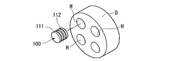
図9は、このようなアルミニウムの押出加工法によって成形される、アルミニウム製熱交換器用偏平多穴チューブ106の一例を示すものである。このチューブ106は扁平チューブ状の周壁106aと、この周壁106aを複数の流路に区画する複数の隔壁106bとから構成されている。そして、この押出偏平多穴チューブ106の製造に好適な押出用ダイス装置として、従来から、以下の特許文献1に記載のインサート型のダイスが知られている。
図10と図11に、特許文献1に記載された従来のインサート型のダイス装置の一例を示すが、この例のダイス100は、図9に示すアルミニウム製の押出偏平多穴チューブ106を押出加工するためのもので、図11に示す円盤状ダイスホルダDに形成された複数の貫通孔Hに挿脱自在とされた、嵌合離脱自在な一対の厚肉円盤ブロック状のメスダイス111とオスダイス112とから構成されている。
FIG. 9 shows an example of a flat
FIG. 10 and FIG. 11 show an example of a conventional insert-type die apparatus described in Patent Document 1. The die 100 of this example extrudes an extruded flat
図10においてメスダイス111は、先のオスダイス112と対向する端面の外周に、環状のメス側インロー部113が形成され、このインロー部113の中央側端面114に凹部115が形成されている。そして、凹部115の中央部には、メスダイス111の中心軸線に沿って一端から他端に向けて貫通するスリット状の孔部116が穿設されている。また、前記凹部115を囲む位置には、2つのねじ穴119と2つのピン穴120とが対称位置に形成されている。
In FIG. 10, the
図10においてオスダイス112は、先のメスダイス111と対向する端面にオス側インロー部122が形成されている。このオスダイス112の中央部には、複数の突起片からなる櫛歯状の突起部123が形成されている。この突起部123は、先のメスダイス111の孔部116内に挿入されることによって孔部116との間に製品形状となる間隙(型孔)を画成するためのものである。そして、オスダイス112には、突起部123の両側に沿うようにオスダイス112の両端面に開口する貫通孔124、124が形成されている。また、オスダイス112において先の貫通孔124、124の周囲側には、2つのねじ穴125と2つのピン126が形成されている。
In FIG. 10, the
そして、前記構成のオスダイス112とメスダイス111を互いのインロー部113、122を嵌合し、ピン126をピン穴120に嵌合させることにより両者を円柱状に一体化してダイス100が構成され、図11に示す円盤状のダイスホルダDに4基のダイス100を装着して全体を図8に示すコンテナ102に取り付けることで押出加工に供することができる。また、この構成のダイス100はダイスホルダDにおいて1基のダイス100が不良となった場合、該当する1基のダイス100のみ、あるいは、該当するメスダイス111かオスダイス112のみ交換することにより押出加工を再開できるので、一体型のダイスに比較して経済的であるなどの利点を有する。
Then, the
また、本願出願人は、先の押出用の型孔を構成する突起部の部分をコア部材としてオスダイスの他の部分と個別に交換できるように構成したダイスについて特許出願している。(特許文献2参照)
この特許文献2に記載の技術によれば、突起部を備えたコア部材とコア部材を装着するコアケースとからオスダイスを構成し、コア部材を摩耗に強い超硬合金から、コアケースを通常のダイス鋼から構成することにより、ダイスの長寿命化を図り、更に、部分的に損耗や破損などを生じた場合、交換性を高めることができるという特徴を有していた。
In addition, the applicant of the present application has applied for a patent on a die configured so that the protruding portion constituting the mold hole for extrusion can be individually replaced with another portion of the male die as a core member. (See Patent Document 2)
According to the technique described in
図12に前記オスダイス112の櫛刃状の突起部123を拡大して示し、図13に突起部123の先端部を更に拡大して示すが、この突起部123は、基板本体部130の先端側に細長い支柱状の突起体131を複数一列に等間隔で配列してなり、各突起体131の先端部に頭部拡径部132を有し、隣接する突起体131の間に間隙133が形成されている。
近年、図9に示す扁平多穴チューブ106を製造する場合、チューブ106の幅寸法Mが同じであっても、穴Hの数が、例えば4個から10個あるいは20個などのように増える傾向にある。これは、穴Hの数が多ければ多いほど熱交換効率が上昇する傾向となり、少しでもチューブ106の熱交換効率を高めようとする要求があるためである。
FIG. 12 is an enlarged view of the comb-
In recent years, when the flat
しかしながら、このように穴Hの数が増えると、図13に示すように突起体131の個々の頭部拡径部132…どうしの隙間Naが小さくなり、しかも、突起体131どうしの隙間Nbも自動的に小さくなることから、アルミニウム素材がこれらの隙間を介して流れ難くなる傾向となる。この結果、押出成形される製品としての扁平多穴チューブ106の隔壁106bの厚さが不足したり、隔壁106bが部分的に欠落するなどの欠陥が生じるおそれを有していた。
However, when the number of the holes H increases in this way, the gap Na between the individual head enlarged
ところで、前述のダイスホルダDにダイス100を取り付けて押出加工を行う構成のダイス装置においては、ステム104がアルミニウム素材103をダイス100に押し付け、アルミニウム素材の流動性を利用してダイス100のオスダイス112側の貫通孔124、124からメスダイス111側の孔部116に突起部123を介して流動させながら押出加工がなされるが、扁平多穴チューブ106が小型薄肉タイプの場合、突起部123と孔部116との隙間が小さく、アルミニウム素材を流動させて押し出す際に高い圧力と温度が作用するので、オスダイス112やメスダイス111をダイス鋼や超硬合金などの耐摩耗性の高い材料から構成していたとしても、長期間使用すると、損耗し易いなどの問題を生じる。
従って、オスダイス112とメスダイス111からなるダイス装置の長寿命化を図るため、あるいは、押出時の損傷や損壊を防止するため、ダイス装置の更なる改良が望まれている。
By the way, in the die apparatus configured to perform extrusion by attaching the die 100 to the die holder D described above, the
Therefore, in order to extend the life of the die device composed of the
本発明は前記した問題に鑑み創案されたものであり、押出製品が複雑な形状であっても、オスダイスの突起部とメスダイスの孔部との隙間によって構成される型孔へ素材をスムーズに流動させることができ、もって欠陥の少ない良好な押出製品を得ることができる押出加工用ダイス装置の提供を目的とする。 The present invention has been devised in view of the above-described problems, and even if the extruded product has a complicated shape, the material smoothly flows into the mold hole formed by the gap between the male die protrusion and the female die hole. Therefore, an object of the present invention is to provide an extrusion die apparatus that can be used to obtain a good extruded product with few defects.
上記の課題を解決するため、本発明は、ダイホルダと、該ダイホルダに形成された支持孔に挿入されて前記ダイホルダに組み込まれた組立ダイスとが具備され、前記組立ダイスを通過させるようにアルミニウムまたはアルミニウム合金の素材ビレットを押圧して前記組立ダイスの型孔を通過させて押出成形自在としたダイス装置において、前記組立ダイスが、櫛刃状の突起部を有するオスダイスと、前記突起部を挿入する孔部を有するメスダイスを備え、前記メスダイスが前記オスダイスを一体化するためのボディを有してなり、前記オスダイスの突起部が、オスダイスの先端部から所定間隔をあけて一列整列状態で複数相互に離間して突出形成された支柱部と、これら支柱部の先端側に支柱部の厚さ方向に膨出形成された頭部と、前記支柱部と頭部の境界部分に形成されている首部とを具備してなり、これら支柱部と首部と頭部と前記メスダイスの孔部との間の間隙が前記型孔を構成してなり、前記一列に隣接する支柱部間に形成される間隙が側面長円形状の素材導入路とされ、前記一列に隣接する支柱部に接続されている頭部間の間隙が等幅の素材通過路とされるとともに、前記素材導入路の前記素材通過路側に素材連絡路が形成され、前記支柱部の首部から前記頭部に至る部分を滑らかな曲線にて連続形成して接続部分に角部が無いように、前記素材連絡路から前記素材通路にかけて角部を生じないように接続され、前記素材導入路と素材通過路の境界部分が角取りされた素材連絡路とされてなることを特徴とする。 In order to solve the above problems, the present invention comprises a die holder and an assembly die inserted into a support hole formed in the die holder and incorporated in the die holder, and aluminum or so as to allow the assembly die to pass therethrough. In a die apparatus in which an aluminum alloy material billet is pressed and passed through a mold hole of the assembly die so as to be extrudable, the assembly die inserts a male die having a comb blade-like protrusion and the protrusion. A female die having a hole, and the female die has a body for integrating the male die, and a plurality of protrusions of the male die are arranged in a line at a predetermined interval from the tip of the male die. The struts that are formed to project apart from each other, the heads that are formed to bulge in the thickness direction of the struts on the leading ends of these struts, and the struts And a neck portion formed at the boundary portion of the head portion, and the gap between the column portion, the neck portion, the head portion, and the hole portion of the female die constitutes the mold hole, and the one row The gap formed between the struts adjacent to each other is a side elliptical material introduction path, and the gap between the heads connected to the struts adjacent to the one row is a uniform width material passage. In addition, a material communication path is formed on the material passage path side of the material introduction path, and a portion from the neck portion to the head portion of the column portion is continuously formed with a smooth curve so that there is no corner portion in the connection portion. , which is connected from the material communication path so as not to cause a corner portion to the material passage, the boundary portion of the front Kimoto material introduction path and the material passage is characterized by comprising been the material communication passage that is skived .
本発明は、前記支柱部と前記頭部と前記首部のコーナー部分の少なくとも1つがアールを付与したコーナー加工されてなり、前記コーナー部のRの範囲が0.01〜0.1mmであることを特徴とする。
本発明は、一列整列状態で隣接する前記支柱部において各支柱部の頭部間の間隔を等幅Naとし、一列整列状態の前記支柱部間の間隔をNbとした場合、Nb/Naの値が1.1〜1.6の範囲であることを特徴とする。
本発明の押出材の製造方法は、先のいずれかに記載の押出加工用ダイス装置を用い、前記の型孔に対し前記素材導入路と素材連絡路と素材通過路を通過させて素材ビレットを押出加工することを特徴とする。
The present invention, at least one will be a corner processed to impart ares range 0.01~0.1mm der Rukoto of R of the corner portion of the corner portion of the said head and the strut neck It is characterized by.
According to the present invention, when the spacing between the heads of each column portion in the column columns adjacent to each other in the aligned state is equal width Na, and the interval between the column portions in the aligned state is Nb, the value of Nb / Na Is in the range of 1.1 to 1.6 .
The extrusion material manufacturing method of the present invention uses the extrusion die apparatus according to any one of the above, and passes the material billet through the material introduction path, the material communication path, and the material passage path with respect to the mold hole. It is characterized by extruding.
以上説明したように本発明によれば、オスダイスの突起部が離間配列された支柱部と頭部と首部とを具備し、これらとメスダイスの孔部との間隙を型孔として構成し、支柱部間に形成される間隙を側面長円形状の素材導入路とし、頭部間の間隙を等幅の素材通過路とし、素材導入路と素材通過路の境界部分を角取りした素材連絡路としてなるので、アルミニウムまたはアルミニウム合金の素材ビレットが型孔を通過して押出成形される場合に、素材ビレットがスムーズに流れる結果、扁平薄型であり、隔壁が複数形成されている複雑な形状の扁平多穴チューブを押出成形する場合であっても隔壁の厚さの均一な高品質のアルミニウムまたはアルミニウム合金の扁平多穴チューブを製造することが可能となる。また、素材ビレットが型孔にスムーズに流れ込む結果、素材ビレットと型孔まわりの摩擦も少なくなるので、オスダイスの突起部において支柱部周りと頭部周りの部分の摩耗が減少し、ダイス装置の長寿命化を図ることができる。
素材ビレットを押し出す際の摩耗の減少を図るには、前記隣接する支柱部間の素材導入路の側面形状が長円形状であり、前記支柱部に隣接する前記頭部間に等幅の素材通過路が形成されたことが好ましい。この形状とすることにより、素材ビレット流動抵抗を確実に削減することができる。
また、オスダイスの突起部の支柱部と頭部と首部のコーナー部分の少なくとも1つをRの範囲0.01〜0.1mmでコーナー加工しておくことで素材ビレット流動時のコーナー部分における流動抵抗を低減してダイス装置の寿命を長くすることができる。
更に、一列整列状態の支柱部において頭部間の間隔Naと支柱部間の間隔Nbにおいて、Nb/Naの値を1.1〜1.6の範囲とすることにより、支柱部の形状と外側のバランスが良好であり、製品表面の平坦性を向上できる。
As described above, according to the present invention, the male die is provided with the support portion, the head portion, and the neck portion that are spaced apart from each other, and the gap between these and the female die hole portion is configured as a mold hole, and the support portion. The gap formed between the sides is an oval-shaped material introduction path, the gap between the heads is an equal width material passage, and the boundary between the material introduction path and the material passage is rounded. Therefore, when the aluminum or aluminum alloy material billet is extruded through the mold hole, the material billet flows smoothly, resulting in a flat and thin flat hole with a complicated shape with multiple flat walls Even when a tube is extruded, a flat multi-hole tube of high quality aluminum or aluminum alloy having a uniform partition wall thickness can be produced. In addition, since the material billet smoothly flows into the mold hole, the friction between the material billet and the mold hole is also reduced, so that the wear around the support post part and the head part is reduced in the protruding part of the male die, and the length of the die device is reduced. Life can be extended.
In order to reduce wear when extruding the material billet, the side surface shape of the material introduction path between the adjacent struts is an oval shape, and a uniform width material passes between the heads adjacent to the struts. It is preferable that a path is formed . By adopting this shape, the billet flow resistance can be reliably reduced.
Moreover, the flow resistance in the corner part at the time of material billet flow is made by corner-processing at least one of the pillar part of the protrusion part of the male die and the corner part of the head part and the neck part in the R range of 0.01 to 0.1 mm. And the life of the dice apparatus can be extended.
Further, by setting the value of Nb / Na in the range of 1.1 to 1.6 at the interval Na between the heads and the interval Nb between the columns in the columns arranged in a line, the shape and the outside of the column are changed. And the flatness of the product surface can be improved.
本発明の押出材の製造方法によれば、支柱部間の側面長円形状の素材導入路から首部間の素材連絡路と、頭部間の素材通過路を介してスムーズに素材ビレットを流動させて少ない抵抗でもって素材ビレットから押出材を製造することができる。従ってダイス装置のオスダイスの突起部とその周りにおいて損耗が少ない状態で押出加工できるので、ダイス装置の寿命を長くすることが可能となり、押出材の連続製造ができる。 According to the method for producing an extruded material of the present invention, the material billet is caused to flow smoothly through the material introduction path between the necks from the side elliptical material introduction path between the support columns and the material passage path between the heads. The extruded material can be produced from the material billet with less resistance. Therefore, since the extrusion process can be performed with little wear on and around the protrusion of the male die of the die device, the life of the die device can be extended, and the extruded material can be continuously manufactured.
以下に本発明の押出加工用ダイス装置の第1実施形態について説明する。
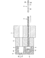
図1は本発明に係る第1実施形態の押出加工用ダイス装置を備えた押出加工装置の一例を示す断面図、図2は同押出加工装置の簡略図、図3はダイスホルダの背面図、図4はダイスホルダに取り付けられる組立ダイスの一例を示す分解図、図5は同組立ダイスのボディ部分の詳細図、図6は同組立ダイスのキャップ部分の詳細図、図7はオスダイスの突起部を拡大して示す斜視図である。
図1に示す実施形態の押出加工装置Aは、アルミニウムまたはアルミニウム合金などからなる素材ビレットBを収容する収容部1を備えた肉厚筒形容器であるコンテナ2と、このコンテナ2の一側に設けられて収容部1の素材ビレットBを押出自在に設けられたステム(加圧手段)3と、コンテナ2においてステム3の設置側と反対側に設けられたダイホルダ5とバックプレート6とボルスター7とを主体として構成されている。
A first embodiment of an extrusion die apparatus according to the present invention will be described below.
FIG. 1 is a cross-sectional view showing an example of an extrusion apparatus equipped with the extrusion die apparatus according to the first embodiment of the present invention, FIG. 2 is a simplified view of the extrusion apparatus, and FIG. 3 is a rear view of the die holder. 4 is an exploded view showing an example of the assembly die attached to the die holder, FIG. 5 is a detailed view of the body portion of the assembly die, FIG. 6 is a detailed view of the cap portion of the assembly die, and FIG. 7 is an enlarged view of the protrusion of the male die. It is a perspective view shown.
An extrusion apparatus A according to the embodiment shown in FIG. 1 includes a
図1に示す実施形態の構造では、ダイリング8の内側に肉厚円盤状のダイホルダ5とバックプレート6とが重ねた状態で挿入されて一体化された構成とされている。
前記ダイホルダ5の内部にはその中心軸回りの対称位置に4つの支持孔9が形成され、これらの支持孔9にそれぞれ図4に示す構造の組立ダイス10が装着されている。
図4に示す如くこの例の組立ダイス10は、円筒ブロック状のボディ11と、このボディ11の中心部に装着される平面視レーストラック形状の厚肉のプレート部材(入れ子部材)12と、プレート部材12の上側においてボディ11に重ねるように装着されるコアケース13と、このコアケース13に挿入されるコア部材15と、このコア部材15を部分的に覆ってコアケース13とボディ11とに装着されるキャップ部材16とを主体として構成されている。これらの部材は素材ビレットBとしてアルミニウム合金を想定した場合、ハイスピード鋼、ダイス鋼あるいは超硬合金から構成されることが好ましいが、特に、高圧の素材ビレットBと接触する部分が多い部材については超硬合金から形成することが望ましい。
In the structure of the embodiment shown in FIG. 1, a thick disc-shaped
Four
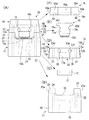
As shown in FIG. 4, the assembly die 10 of this example includes a cylindrical block-shaped
前記ボディ11は、図5に詳細に示す如く、円筒状の基台部20と、この基台部20の上部側から傾斜面21を有して若干先窄まり状に形成された嵌合部22と、この嵌合部22の上部両側に180゜間隔で突出形成された2つの突起部23とを主体として構成されている。また、各突起部23はそれらの中央部分で嵌合溝部24を介して2つに分割されているとともに、各突起部23の外周面は上窄まり状のテーパを有した傾斜面23aとされている。更に、基台部20の上面側において左右の突起部23、23の間の部分は幅広で先の嵌合溝部24よりも若干深い位置にあって基台部20の両端部まで達する凹溝部30が形成されている。
前記基台部20の中央側には基台部20の中央部を貫通するスリット状の長円形状の中央孔25が形成されるとともに、基台部20の中央上部側には中央孔25に連通する入れ子用の挿入孔26が先の凹溝部30の中央部に開口するように形成されていて、この挿入孔26に前記プレート部材(入れ子部材)12が嵌め込まれるように構成されている。また、基台部20の両側には基台部20と嵌合部21とを貫通して嵌合溝部24の中央部に開口する取付孔27が形成されている。これらの取付孔27は、後述するコアケース13とキャップ部材16とをボディ11に装着した場合にそれらの両端側に後述の如く形成されている孔と位置合わせができるように形成されている。
As shown in detail in FIG. 5, the
A slit-like oval
前記ボディ11には、スリット状の中央孔25の両側を挟む位置にボディ11の底面と挿入孔26の底面に開口する冷媒流入路20aと冷媒流出路20bが形成され、中央孔25の一側に隣接する一対の冷媒流入路20aが挿入孔26の底面に形成されている凹部状の冷媒流路20bにより接続されて側面視コ字状の冷媒流路20Aが形成されている。
In the
前記プレート部材(入れ子部材)12はその中央部にスリット状の長円形の孔部31が形成され、この孔部31は先のボディ11の中央孔25とほぼ同じ横断面形状とされている。このプレート部材12は前記ボディ11の挿入孔26に嵌め込み自在な大きさとされていて、挿入孔26にプレート部材12を嵌合した場合にプレート部材12の孔部31がボディ11の凹溝部30の中央部に位置して前記ボディ11の中央孔25と連通するように形成されている。
The plate member (nesting member) 12 has a slit-like
図4に示すコアケース13は、前記ボディ11における2分割された突起部23の間の嵌合溝部24に、コアケース13の左右両端部13aを嵌め込み自在な大きさの横長の板状に形成され、コアケース13の両端部13aを嵌合溝部24に嵌め込み接合した状態において、前記ボディ11の突起部23の外側面の凸曲面状の傾斜面23aに沿うように、コアケース13の両端部13aの外側面には凸曲面状の傾斜面13bが形状されている。
The
前記コアケース13は、前記嵌合溝部24の溝底側に向く底面13cとその両側に配置された前述の傾斜面13bと、これらの傾斜面13b、13bと底面13cに連続する支持面13d、13dと、前記底面13cに対向する支持面13eを有してなり、コアケース13の中央部には、後述のコア部材15を嵌め込むためのスリット状の嵌合孔35がコアケース13を貫通して底面13cと支持面13eの中央部に開口するように形成され、底面13cにおいて嵌合孔35の開口部の両側には突起部36が形成されている。
更に、コアケース13の両端部13aには、コアケース13の両端部13aを嵌合溝部24に嵌め込み接合した状態において前述のボディ11の取付孔27に連通するための挿通孔37が両端部13aを個々に貫通するように形成されている。また、前記突起36の底面13cからの突出長さは、図4(A)に示す如くコアケース13の両端部13aをボディ11の嵌合溝部24に嵌め込み接合した状態において、突起部36の先端がボディ11内のプレート部材12と若干の間隙をあけて対向するように形成されている。
次にコアケース13の支持面13d、13dの中央側に、突起部36、36の間に位置して先の嵌合孔35の延在方向に沿って支持面13dの上部側から底部側にまで延出する段部13gが形成されている。これらの段部13g、13gは押出加工時にコアケース13に沿って流動する素材ビレットの流れを円滑にするための作用を奏する。
The
Further, the both
Next, on the center side of the support surfaces 13d and 13d of the
前記コア部材15は、前記コアケース13のスリット状の嵌合孔35に挿通自在な大きさの扁平のヘッド部15aとヘッド部15aの先端部側に形成された櫛刃状の突起部15bとヘッド部15aの後端側に左右に突出するように形成されたストッパ片15dとからなり、ヘッド部15aの後端部左右側において各ストッパ片15dの基端部側には半円形状の受部15eが形成されている。この構成のコア部材15は、ヘッド部15aを先のコアケース13の嵌合孔35に挿通すると同時に、ストッパ片15dがコアケース13の支持面13eに当接することにより、ヘッド部15の櫛刃部15bを先のプレート部材12の長円形状の孔部31に部分的に対峙させて、孔部31の開口部と櫛刃部15bの先端部との間に隙間を形成することで、この隙間を組立ダイス10における押出成形用の型孔10Aとするように構成されている。
The
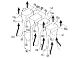
前記突起部15bの形状は詳細には図7に示す構造とされている。まず、板状のヘッド部15aの先窄まり状の先端部の先端側に、相互に所定の間隔離間して一列に複数の支柱部15fが立設され、各支柱部15fの先端部に頭部15gが形成されている。
前記支柱部15fの互いに対向する側面側は湾曲面15hとされ、隣接する支柱部15f、15f間の底部は先の湾曲面15hに連続する凹曲面15iとされていて、隣接する支柱部15f、15f間の側面の輪郭形状は長円形状とされている。
これら支柱部15fの上部側には首部15jを介して頭部15gが形成されている。首部15jと頭部15gは支柱部15fと同じ程度の幅(図7のx方向に沿う幅)とされているが、支柱部15fの厚さ方向(図7のx方向に直交する方向の厚さ)に沿う頭部15gの厚さは支柱部15fの厚さより大きくされている。また、隣接する頭部15g、15gの間隙は頭部15gの厚さ方向(図7のx方向に直交する方向)に等幅(幅:Na)とされ、一列に配列された支柱部15f、15fの間隔Nbもそれぞれ同じ値とされている。
以上構成の支柱部15fと首部15jと頭部15gにより、隣接する支柱部15f、15f間に側面視長円形状の素材導入路15kが形成され、隣接する頭部15g、15g間に等幅の素材通過路15mが形成され、素材導入路15kと素材通過路15mとの境界部分は素材連絡路15nとされている。従って、図7に示す如く支柱部15f、15fの間の部分には側面視ひょうたん型の間隙が形成されている。
また、支柱部15fの上部から首部15jを介して頭部15gに至る部分は滑らかな曲線にて連続形成されて接続部分に角部が無いように形成されているので、素材連絡路15nは素材導入路15kから素材通過路15mにかけて角部を生じないように両方を滑らかに接続する。また、頭部15gは平面視略長方形状でそのコーナ部となる角部にアール部15pを形成してなるコーナー加工が施されている。
これらの支柱部15f、首部15j、頭部15gのコーナ部のアール加工は研削、ワイヤーカット法などにより必要な曲率で形成することができる。これらコーナ部のRの範囲はR0.01〜R0.1(mm)の範囲が好ましく、Rが大きくなると製品断面が大となり、重量増となる。
また、図7に示すNb/Naの値は、1.1〜1.6の範囲であることが望ましく、この範囲であれば、外側の形状と支柱部15fのバランスが良好であり、製品表面の平坦性が向上する効果がある。
The shape of the
The side surfaces of the
A
The
In addition, since the part from the upper part of the
The rounding of the corner portions of the
In addition, the value of Nb / Na shown in FIG. 7 is desirably in the range of 1.1 to 1.6, and within this range, the balance between the outer shape and the
前記キャップ部材16は、先のコアケース13の支持面13eに当接される所望の肉厚の横長の板状の部材であり、コアケース13の支持面13eに当接される底面16aと、この底面16aに連続する左右の側面16bと、正面または背面となる主面16dと、先の底面16aに対向する天面16eを有してなる。
また、キャップ部材16の主面16dの中央には、キャップ部材16とコアケース13とを接合一体化した際に先に説明のコアケース13に形成されている段部13gと連続する段部16gが形成されている。このキャップ部材16の段部16gにあっても先のコアケース13の段部と同様に押出加工時の素材ビレットの流れを円滑にする。
The
Further, at the center of the
前記底面部16aの中央部には先のコア15のストッパ片15dを嵌め込み覆うことができる凹部16fが形成され、キャップ部材16の両端部側にはキャップ16をコアケース13の支持面13eに当接させた状態においてコアケース13の挿通孔37に連通するためのネジ穴40が形成されている。
これらのネジ穴40は、ボディ11に対して図4(A)に示すようにプレート部材12とコアケース13とコア部材15とキャップ部材16とを装着した状態において、コアケース13の挿通孔37とボディ11の段付き孔型の取付孔27とに連通するように形成されていて、これらの孔を貫通してネジ穴40にボルトなどの締結具を螺合することでボディ11とプレート部材12とコアケース13とコア部材15とキャップ部材16とを強固に一体化できるように構成されている。
A
These screw holes 40 are formed in the insertion holes 37 of the
以上説明の如く構成されたボディ11に、図4(A)に示す如くプレート部材12とコアケース13とコア部材15とキャップ部材16とを装着し、ボディ11の取付孔27とコアケース13の挿通孔37を介してボルトをキャップ部材16のネジ穴40に螺合することによりこれらを一体化し、組立ダイス10とすることができる。
この組立ダイス10を4基用意し、これらを図1に示すダイホルダ5の4つの支持孔9に個々に挿入することでダイホルダ5が完成する。
As shown in FIG. 4A, the
Four assembly dies 10 are prepared, and these are individually inserted into the four
ダイホルダ5の支持孔9は、コンテナ2の収容部1側に向いて若干先窄まり状となっている輪郭釣鐘型形状とされている。この支持孔9において収容部1側が導入口9aとされ、この導入口9aの部分から若干拡がるように形成された保持孔9bの部分に図4(A)に示す如く組み立てられた組立ダイス10が挿入され、固定されている。支持孔9の導入口9aの部分にはこの導入口9aの中心部を通過するようにロッド状のブリッジ部41が形成されるとともに、導入口9aの開口周縁部には、ダイホルダ5の収容部1側の面に段部42を形成して導入口9aの開口部が拡張されている。
The
本実施形態において、円盤型のダイホルダ5には図3に示す如くその中心部を囲む点対称位置に等間隔で4つの支持孔9が設けられ、これら4つの支持孔9において各導入口9aに形成されている段部42の一例形状を図3に示す。ダイホルダ5において、4つの導入口9aは収容部1側から見ると図3に示す如く個々にブリッジ部41にて2分割されたように見えているので、実際に1つの導入口9aに対してそれぞれ対になるように上下に段部42a、42bが形成されている。
In the present embodiment, the disk-shaped
これらの支持孔9に組立ダイス10を嵌合して組立ダイス10をダイホルダ5に取り付ける場合、組立ダイス10のキャップ部材16をブリッジ部41の長さ方向に揃って隣接するように配置する。これにより、支持孔9の内部側に、ブリッジ部41の両側に配置された導入口9a、9aから、キャップ部材16の幅方向両側の空間部と、コアケース13の幅方向両側の空間部に連通する素材ビレットの流動路を画成することができる。また、この流動路はボディ11の凹溝部30に至り、組立ダイス10のコア部材15とプレート部材12の開口部との間に画成されている型孔10Aを介し、プレート部材12の内部空間を通過してボディ11の中央孔25に至る一連の流動路を構成する。
When the assembly die 10 is fitted to the support holes 9 and the assembly die 10 is attached to the
図3に示すダイホルダ5における段部42の配置構成において、4つの導入口9aの配置された領域において、内側よりに位置する4つの段部42aは、導入口9aの開口部の半円形状の部分を囲み、それよりも若干縦横ともに大きい正面視横長の長方形状に形成され、4つの導入口9aの配置された領域の外側よりに位置する他の4つの段部42bは、先の段部42aよりもダイホルダ5の外側よりの外側部分に膨出部42cが形成されて大きくされ、その他の部分は段部42aと同等の大きさに形成されてなる。
図3では一例として段部42bにおいてそれらの外側部分に膨出部42cを左右方向及び上下方向側に若干膨出させた形状として表記しているが、この膨出形状は一例に過ぎない。本発明では図3に示す形状に限るものではなく、4つの導入口9aがダイホルダ5の中央部側に90゜間隔で配置された場合、4つの導入口9aが占める領域の外側の領域に位置する段部42bの端部側を図3の上下左右のいずれかの方向に必要な幅のみ、任意の方向に他の段部と干渉しないように拡張すれば良い。このように段部を拡張してなる膨出部42bを備えることで、後述する素材ビレット3を押し出す場合の流動抵抗を低減することができる。
In the arrangement configuration of the
In FIG. 3, as an example, the stepped
次に、前述の如く4つの支持孔9が形成されているダイホルダ5の背面側に図1に示す如く設けられたバックプレート6にはダイホルダ5の各支持孔9に連通する通過孔6aが形成され、更にその背面側に設けられているボルスター7にも同様に通過孔7aが形成され、組立ダイス10にて押出加工した押出部品Cを移動することができるように構成されている。なお、図1の構造ではボルスター7の外側に更にプッシュ部材Pが設けられているが、この部材は略しても差し支えない。
Next, through
以上説明の如く構成された押出加工装置により熱交換器用の扁平多穴チューブなどの押出部品を製造するには、組立ダイス10をダイホルダ5に装着して図1に示す押出加工装置にセットし、収容部1にアルミニウムあるいはアルミニウム合金などの素材ビレットBを収容し、この素材ビレットBにステム3で圧力を加える。
この操作により素材ビレットBは収容部1から段部42a、42bを介してダイホルダ5の導入口9a側に流入し、キャップ部材16の幅方向両側の支持孔内空間部と、コアケース13の幅方向両側の支持孔内空間部を通過し、ボディ11の凹溝部30側に至り、組立ダイス10のコア部材15とプレート部材12の開口部との間に画成されている型孔10Aを通過し、この型孔10Aの形状に加工された後、バックプレート6の通過孔6aとボルスター7の通過孔7aとを通過して押出部品Cとして得られる。
本実施形態では図4に示す如く櫛刃状の突起部15bと長円形状の孔部31を有するプレート部材12とにより画成される型孔10Aにより、図2に概略で示す横断面形状の扁平多穴チューブ(押出部品)Cが得られる。この扁平多穴チューブCは、横断面長円形状の周壁50の内側に複数の隔壁51が平行に所定の間隔で複数並列形成された扁平筒形のものとなる。
In order to manufacture extruded parts such as flat multi-hole tubes for heat exchangers by the extrusion apparatus configured as described above, the assembly die 10 is mounted on the
By this operation, the material billet B flows into the
In this embodiment, as shown in FIG. 4, a
更に、本実施形態の構造では型孔10Aをプレート部材12の孔部31とコア部材15の櫛刃状の突起部15bにより画成しているが、素材ビレットBは型孔10Aにおいて、長円形状の素材導入路15kに初め流入し、続いて素材連絡路15nを介して滑らかに素材通過路15mを通過するので、図13に示す従来構造の突起部123の周囲を通過する場合よりも少ない抵抗で滑らかに流動する結果、押出圧力の低減、突起部15bを構成する支柱部15f、首部15j、頭部15gの損耗を抑制することができる。この結果、組立ダイス10の寿命を延ばすことができる。
Further, in the structure of the present embodiment, the
ところで、以上説明した押出加工工程において、ステム3の押圧力により素材ビレットBに押出方向の面方向に均等に圧力を印加して4つの組立ダイス10側に押し出して成形しようとしても、4つの導入口9aの全面積において如何なる部分であっても等速で素材ビレットBが流動することにはならない。即ち、4つの導入口9aを図3に示すように視認した場合、ダイホルダ5の中心に近い側の導入口9aの一部分とダイホルダ5の外周に近い側の導入口9aの一部分との比較では、中心に近い側を流動する素材の流速が、外周に近い側を流動する素材の流速よりも早くなろうとする。
そこで本実施形態では、4つの導入口9aを配置した領域に位置する段部42において外側部分に膨出部42cを形成して段部の面積を大きくして導入口9aに素材を流れ込み易くしたので、4つの導入口9aの全断面積においてできるだけ素材ビレットBの流動状態を均一化できる結果として組立ダイス10の各部分に均等な圧力を付加することができ、組立ダイス10の各部分に対して適正な押出圧力を印加できる結果として、隔壁51の部分に偏肉の生じていない、均一な肉厚の高品質の扁平多穴チューブCを製造することができる。
By the way, in the extrusion process described above, even if an attempt is made to apply the pressure evenly in the surface direction of the extrusion billet B to the raw billet B by the pressing force of the stem 3 and to extrude it to the four assembly dies 10 side, four introductions are made. The material billet B does not flow at a constant speed in any part of the entire area of the
Therefore, in the present embodiment, a bulging
また、本実施形態のダイス装置では、導入口9aの素材ビレットB側の開口部に段部42a、42bを設けることで、導入口9aに対する素材ビレットBの導入部分での面積を拡大し、素材導入時の流動抵抗を減少させているので、段部を設けていない従来のダイス装置よりも円滑な素材の流れを生み出すことができ、少ない抵抗で押出加工ができる特徴を有する。
Further, in the dice apparatus of the present embodiment, by providing
次に、本実施形態のダイス装置では、組立ダイス10のキャップ部材16の素材ビレットB側にダイホルダ5のブリッジ部41を設け、このブリッジ部41が素材ビレットBからの圧力を直接受けるように構成し、ブリッジ部41の背後側に存在する組立ダイス10のキャップ部材16に作用する素材ビレットからの圧力を軽減したので、組立ダイス10の特にキャップ部材16に押出成形時の圧力が直に作用することを抑制することができ、ブリッジ部41によりキャップ部材16への圧力を軽減することができ、ひいては組立ダイス10の他の部分への印加圧力軽減をなし得るとともに、組立出ダイス10を保護し、それらの破損や損傷を防止あるいは抑制することができる。
Next, in the die apparatus according to the present embodiment, the
次に、先の実施形態のダイス装置では、キャップ部材16の主面16d、16dの中央部に段部16gを形成しているので、この段部16gに沿って素材ビレットBが流動する際の案内としなって素材ビレットの流れを安定化する。これにより素材ビレットBの流動性を制御して流動抵抗を軽減する。
そして、この素材ビレットBの流れは次にコアケース13の段部13gに至り、段部13gにおいても素材ビレットBの流動性を整えつつ櫛刃状の突起部15bとプレート部材12の孔部31との間に画成されている型孔10Aを通過して目的の形状に押出加工される。本実施形態のダイス装置では、このようにキャップ部材16とコアケース13のいずれにおいても素材ビレットBの流れを整えることができ、型孔10Aまでの素材ビレットBの流れを円滑にすることができ、押出加工においてもできる限り円滑な加工ができる特徴を有する。
Next, in the dice apparatus of the previous embodiment, the
The flow of the material billet B then reaches the stepped
また、本実施形態において組立ダイス10を支持孔9に嵌合した場合、メスダイスのボディ11の傾斜面23aが支持孔9の先窄まり形状の傾斜面9cに合致して位置決めとなるので、組立ダイス10の径方向及び長軸方向への位置ずれを防止することができ、この結果として肉厚変動の無い押出部品を製造することが可能であり、例えば、隔壁51の部分に偏肉の生じていない、均一な肉厚の高品質の扁平多穴チューブCを製造することができる。
Further, in this embodiment, when the assembly die 10 is fitted into the
更に本実施形態において、組立ダイス10を支持孔9に嵌合した場合、コアケース13の両端部に形成されている傾斜面13bが支持孔9の先窄まり状の内面と合致するので支持孔9の内面に挟まれた状態でコアケース13の位置決めもなされ、コアケース13の位置ずれも抑制される結果として、肉厚変動の無い押出部品を製造することが可能であり、例えば、隔壁51の部分に偏肉の生じていない、均一な肉厚の高品質の扁平多穴チューブCを製造することができる。
Furthermore, in this embodiment, when the assembly die 10 is fitted into the
以上説明したように本実施形態のダイス装置によれば、突起部15bが離間配列された支柱部15fと頭部15gと首部15jとを具備し、これらとメスダイスの孔部31との間隙を型孔10Aとして構成し、支柱部15f間に形成される間隙を側面長円形状の素材導入路とし、頭部間の間隙を等幅の素材通過路15mとし、素材導入路15kと素材通過路15nの境界部分を角取りした素材連絡路15nとしてなるので、素材ビレットBが型孔を通過して押出成形される場合に、素材ビレットBがスムーズに流れる結果、扁平薄型であり、隔壁106bが複数形成されている複雑な形状の扁平多穴チューブを押出成形する場合であっても隔壁の厚さの均一な高品質の扁平多穴チューブを製造することが可能となる。
また、素材ビレットBが型孔10Aにスムーズに流れ込む結果、素材ビレットBと型孔10Aまわりの摩擦も少なくなるので、オスダイスの突起部15bにおいて支柱部周りと頭部周りの部分の摩耗が減少し、ダイス装置の長寿命化を図ることができる。
更に、素材ビレットBを押し出す際の摩耗の減少を図るには、素材導入路15kの側面形状と前記素材通過路15mの側面形状とを合わせた側面輪郭形状をひょうたん型とすることが好ましい。ひょうたん型とすることにより、素材ビレットBの流動抵抗を確実に削減することができる。
また、オスダイスの突起部15の支柱部15fと頭部15gと首部15jのコーナー部分の少なくとも1つをR付きのコーナー加工しておくことで素材ビレットBの流動時のコーナー部分における流動抵抗を低減してダイス装置の寿命を長くすることができる。
As described above, according to the dice apparatus of the present embodiment, the
Further, as the material billet B smoothly flows into the
Furthermore, in order to reduce wear when the material billet B is pushed out, it is preferable that the side surface contour shape combining the side surface shape of the
Moreover, the flow resistance in the corner part at the time of the flow of the billet B is reduced by processing at least one of the corner parts of the
A…押出加工装置、B…素材ビレット、C…扁平多穴チューブ(押出部品)、1…収容部、2…コンテナ、3…ステム、5…ダイホルダ、6…バックプレート、7…ボルスター、8…ダイリング、9…支持孔、10…組立ダイス、10A…型孔、11…ボディ、12…プレート部材(入れ子部材)、13…コアケース、13b…傾斜面、15…コア部材、15b…突起部、15f…支柱部、15g…頭部、15j…首部、15k…素材導入路、15m…素材通過路、15n…素材連絡路、15p…アール部、16…キャップ部材、 A ... Extrusion device, B ... Material billet, C ... Flat multi-hole tube (extruded part), 1 ... Housing, 2 ... Container, 3 ... Stem, 5 ... Die holder, 6 ... Back plate, 7 ... Bolster, 8 ... Die ring, 9 ... support hole, 10 ... assembly die, 10A ... mold hole, 11 ... body, 12 ... plate member (nesting member), 13 ... core case, 13b ... inclined surface, 15 ... core member, 15b ... projection , 15f ... strut part, 15g ... head part, 15j ... neck part, 15k ... material introduction path, 15m ... material passage way, 15n ... material connection path, 15p ... round part, 16 ... cap member,
Claims (4)
前記組立ダイスが、櫛刃状の突起部を有するオスダイスと、前記突起部を挿入する孔部を有するメスダイスを備え、前記メスダイスが前記オスダイスを一体化するためのボディを有してなり、
前記オスダイスの突起部が、オスダイスの先端部から所定間隔をあけて一列整列状態で複数相互に離間して突出形成された支柱部と、これら支柱部の先端側に支柱部の厚さ方向に膨出形成された頭部と、前記支柱部と頭部の境界部分に形成されている首部とを具備してなり、これら支柱部と首部と頭部と前記メスダイスの孔部との間の間隙が前記型孔を構成してなり、
前記一列に隣接する支柱部間に形成される間隙が側面長円形状の素材導入路とされ、前記一列に隣接する支柱部に接続されている頭部間の間隙が等幅の素材通過路とされるとともに、前記素材導入路の前記素材通過路側に素材連絡路が形成され、前記支柱部の首部から前記頭部に至る部分を滑らかな曲線にて連続形成して接続部分に角部が無いように、前記素材連絡路から前記素材通路にかけて角部を生じないように接続され、前記素材導入路と素材通過路の境界部分が角取りされた素材連絡路とされてなることを特徴とする押出加工用ダイス装置。 A die holder and an assembly die inserted into a support hole formed in the die holder and incorporated in the die holder are provided. The assembly die is pressed by pressing a billet of aluminum or aluminum alloy so as to pass through the assembly die. In a die device that can be extruded by passing through the mold hole,
The assembly die includes a male die having a comb blade-like protrusion and a female die having a hole for inserting the protrusion, and the female die has a body for integrating the male die,
The protrusions of the male dies protrude from the front ends of the male dies at a predetermined interval and are projected in a row and spaced apart from each other, and swell in the thickness direction of the support portions at the front ends of these support portions. And a neck portion formed at a boundary portion between the column portion and the head portion, and a gap between the column portion, the neck portion, the head portion, and the hole portion of the female die is formed. Comprising the mold cavity;
A gap formed between the column portions adjacent to the one row is a side oval material introduction path, and a gap between the heads connected to the column portions adjacent to the one row is a uniform width material passage path. In addition, a material communication path is formed on the material passage path side of the material introduction path, and a portion from the neck portion to the head portion of the support column is continuously formed with a smooth curve so that there is no corner portion at the connection portion. features such, which is connected from the material communication path so as not to cause a corner portion to the material passage, that boundary portion of the front Kimoto material introduction path and the material passage is formed by a material connection path that is skived Die equipment for extrusion.
Priority Applications (5)
| Application Number | Priority Date | Filing Date | Title |
|---|---|---|---|
| JP2010194841A JP5686552B2 (en) | 2010-08-31 | 2010-08-31 | Extrusion die apparatus and method for producing extruded material using the same |
| CN201180031667.2A CN103003001B (en) | 2010-06-30 | 2011-06-30 | Extrude die for processing device |
| PCT/JP2011/064999 WO2012002474A1 (en) | 2010-06-30 | 2011-06-30 | Extrusion die device |
| US13/806,938 US8821147B2 (en) | 2010-06-30 | 2011-06-30 | Extrusion die device |
| EP11800936.4A EP2589443A4 (en) | 2010-06-30 | 2011-06-30 | Extrusion die device |
Applications Claiming Priority (1)
| Application Number | Priority Date | Filing Date | Title |
|---|---|---|---|
| JP2010194841A JP5686552B2 (en) | 2010-08-31 | 2010-08-31 | Extrusion die apparatus and method for producing extruded material using the same |
Publications (2)
| Publication Number | Publication Date |
|---|---|
| JP2012050999A JP2012050999A (en) | 2012-03-15 |
| JP5686552B2 true JP5686552B2 (en) | 2015-03-18 |
Family
ID=45904992
Family Applications (1)
| Application Number | Title | Priority Date | Filing Date |
|---|---|---|---|
| JP2010194841A Expired - Fee Related JP5686552B2 (en) | 2010-06-30 | 2010-08-31 | Extrusion die apparatus and method for producing extruded material using the same |
Country Status (1)
| Country | Link |
|---|---|
| JP (1) | JP5686552B2 (en) |
Families Citing this family (3)
| Publication number | Priority date | Publication date | Assignee | Title |
|---|---|---|---|---|
| JP5987368B2 (en) | 2011-07-05 | 2016-09-07 | 株式会社リコー | Illumination device and projection device |
| JP6019762B2 (en) * | 2012-05-30 | 2016-11-02 | 日亜化学工業株式会社 | Light source device and projector provided with the light source device |
| CN118577642B (en) * | 2024-08-07 | 2024-11-22 | 滁州瑞达新能源材料有限公司 | Aluminum extrusion splitter combination die |
Family Cites Families (7)
| Publication number | Priority date | Publication date | Assignee | Title |
|---|---|---|---|---|
| US3527079A (en) * | 1966-08-01 | 1970-09-08 | Dow Chemical Co | Feeder hole die with improved metal flow |
| JPH06114436A (en) * | 1992-10-06 | 1994-04-26 | Showa Alum Corp | Hollow material extrusion die |
| JP2564088B2 (en) * | 1993-04-30 | 1996-12-18 | 有限会社矢野エンジニアリング | Extrusion tool for simultaneous extrusion of multiple hollow materials |
| JP3305429B2 (en) * | 1993-06-29 | 2002-07-22 | 昭和電工株式会社 | Perforated tube material for heat exchanger, extrusion die for producing the tube material, and method for producing the tube material |
| JP2001191109A (en) * | 1999-12-28 | 2001-07-17 | Yano Engineering:Kk | Extruding die for hollow material, and mandrel for extruding die |
| EP2104577B1 (en) * | 2006-12-11 | 2011-08-03 | Ohio University | Apparatus and method for extruding micro-channel tubes |
| JP5641833B2 (en) * | 2010-09-07 | 2014-12-17 | 昭和電工株式会社 | Extrusion dies |
-
2010
- 2010-08-31 JP JP2010194841A patent/JP5686552B2/en not_active Expired - Fee Related
Also Published As
| Publication number | Publication date |
|---|---|
| JP2012050999A (en) | 2012-03-15 |
Similar Documents
| Publication | Publication Date | Title |
|---|---|---|
| WO2012002474A1 (en) | Extrusion die device | |
| JP5485024B2 (en) | Extrusion die equipment | |
| JP5635380B2 (en) | Extrusion die apparatus and extrusion processing method | |
| JP5727801B2 (en) | Extrusion die apparatus and extrusion processing method | |
| JP5686552B2 (en) | Extrusion die apparatus and method for producing extruded material using the same | |
| JP5624397B2 (en) | Extrusion die equipment | |
| US4814187A (en) | Honeycomb structural body-extruding die apparatus | |
| JP5504044B2 (en) | Extrusion die apparatus and method for manufacturing extruded parts | |
| CN111182815A (en) | Mold insert and method of making a mold insert | |
| JP4938500B2 (en) | Dies for metal material extrusion | |
| JP5773586B2 (en) | Extrusion die, extrusion die apparatus, and extrusion part manufacturing method | |
| KR101240494B1 (en) | Extrustion molding enable to improve durability and abrasion resistance for aluminum tube | |
| JP2003220407A (en) | Split die and die-nib thereof | |
| CN217451541U (en) | Extrusion die of hollow square-mouth aluminum alloy section | |
| KR20040075855A (en) | Extrusion tool, method for manufacturing shaped article with fins, and heat sink | |
| US6351979B1 (en) | Extrusion die | |
| JP2007307614A (en) | Extrusion die | |
| US10974315B2 (en) | Production method and production apparatus of continuously cast metal rod | |
| JP3763790B2 (en) | Dies for extruding perforated tube material | |
| US10960462B2 (en) | Production method and production apparatus of continuously cast metal rod | |
| JP6254074B2 (en) | Extrusion dies for forming flat multi-hole tubes | |
| JP2007061867A (en) | Die-casting die and method for producing die-casting die | |
| JP2003326309A (en) | Die for extruding perforated tube material and method for manufacturing perforated tube using the same | |
| JP2008030117A (en) | Extrusion die for metallic material | |
| JP4938504B2 (en) | Dies for metal material extrusion |
Legal Events
| Date | Code | Title | Description |
|---|---|---|---|
| A621 | Written request for application examination |
Free format text: JAPANESE INTERMEDIATE CODE: A621 Effective date: 20130729 |
|
| A131 | Notification of reasons for refusal |
Free format text: JAPANESE INTERMEDIATE CODE: A131 Effective date: 20140624 |
|
| A521 | Request for written amendment filed |
Free format text: JAPANESE INTERMEDIATE CODE: A523 Effective date: 20140825 |
|
| TRDD | Decision of grant or rejection written | ||
| A01 | Written decision to grant a patent or to grant a registration (utility model) |
Free format text: JAPANESE INTERMEDIATE CODE: A01 Effective date: 20150113 |
|
| A61 | First payment of annual fees (during grant procedure) |
Free format text: JAPANESE INTERMEDIATE CODE: A61 Effective date: 20150120 |
|
| R150 | Certificate of patent or registration of utility model |
Ref document number: 5686552 Country of ref document: JP Free format text: JAPANESE INTERMEDIATE CODE: R150 |
|
| R250 | Receipt of annual fees |
Free format text: JAPANESE INTERMEDIATE CODE: R250 |
|
| R250 | Receipt of annual fees |
Free format text: JAPANESE INTERMEDIATE CODE: R250 |
|
| R250 | Receipt of annual fees |
Free format text: JAPANESE INTERMEDIATE CODE: R250 |
|
| R250 | Receipt of annual fees |
Free format text: JAPANESE INTERMEDIATE CODE: R250 |
|
| R250 | Receipt of annual fees |
Free format text: JAPANESE INTERMEDIATE CODE: R250 |
|
| S111 | Request for change of ownership or part of ownership |
Free format text: JAPANESE INTERMEDIATE CODE: R313111 |
|
| R350 | Written notification of registration of transfer |
Free format text: JAPANESE INTERMEDIATE CODE: R350 |
|
| LAPS | Cancellation because of no payment of annual fees |