JP5684069B2 - Pile structure - Google Patents
Pile structure Download PDFInfo
- Publication number
- JP5684069B2 JP5684069B2 JP2011171631A JP2011171631A JP5684069B2 JP 5684069 B2 JP5684069 B2 JP 5684069B2 JP 2011171631 A JP2011171631 A JP 2011171631A JP 2011171631 A JP2011171631 A JP 2011171631A JP 5684069 B2 JP5684069 B2 JP 5684069B2
- Authority
- JP
- Japan
- Prior art keywords
- pile
- ready
- root
- plate
- outer diameter
- Prior art date
- Legal status (The legal status is an assumption and is not a legal conclusion. Google has not performed a legal analysis and makes no representation as to the accuracy of the status listed.)
- Expired - Fee Related
Links
Images


Landscapes
- Piles And Underground Anchors (AREA)
- Foundations (AREA)
Description
本発明は、杭構造に関する。詳しくは、構造物の基礎を支持する杭の構造に関する。 The present invention relates to a pile structure. In detail, it is related with the structure of the pile which supports the foundation of a structure.
従来より、構造物の基礎には杭が用いられるが、地震時にこの杭に作用する引抜き力に抵抗するため、引抜き耐力を高めた杭が知られている。
構造物の基礎を支持する杭には鉛直荷重により常時圧縮力が作用しているが、地震時には、水平荷重により曲げ応力やせん断応力が生じるとともに、転倒モーメントにより引張力が生じ、杭に引抜き方向の力が作用する。
Conventionally, piles are used for the foundations of structures, but piles with increased pulling strength are known in order to resist pulling forces acting on these piles during an earthquake.
The pile that supports the foundation of the structure is always subjected to compressive force due to the vertical load, but in the event of an earthquake, the horizontal load causes bending stress and shear stress, and the overturning moment causes tensile force. The force of acts.
上述の水平荷重や鉛直荷重に対して杭が所定の抵抗力を発揮するためには、地盤との応力伝達上、所定の杭間隔が必要であるが、大きな地震力に抵抗するためには、杭の本数を増やすか、もしくは杭を大口径にする必要があり、杭の鉄筋量が増大するとともに基礎スラブも厚くなって、基礎にかかるコストが嵩む場合がある。
そこで、基礎にかかるコストを削減するために、杭の内部に引張力を負担するアンカー材を埋設することで、杭径や鉄筋量を増さずに大きな引張力に抵抗する方法が提案されている(特許文献1参照)。
In order for the pile to exert a predetermined resistance against the horizontal load and the vertical load described above, a predetermined pile interval is necessary for stress transmission with the ground, but in order to resist a large seismic force, It is necessary to increase the number of piles or to make the piles have a large diameter, which increases the amount of reinforcing bars of the piles and thickens the foundation slab, which may increase the cost of the foundations.
Therefore, in order to reduce the cost of the foundation, a method has been proposed in which an anchor material bearing the tensile force is buried inside the pile, thereby resisting a large tensile force without increasing the pile diameter or the amount of reinforcing bars. (See Patent Document 1).
この特許文献では、杭は、先端部分が拡底された杭穴と、当該杭穴の拡底部分に設けられた根固め層と、杭穴に挿入されて根固め層に定着した中空の既製杭と、この既製杭の先端面に設けられた支圧板と、既製杭に挿通されて支圧板に連結されたアンカー材と、を備える。この既製杭の先端部分の外周面には、環状のリブが形成されている。 In this patent document, a pile includes a pile hole whose tip is widened, a root consolidation layer provided at the bottom wide portion of the pile hole, and a hollow ready-made pile that is inserted into the pile hole and fixed to the root consolidation layer. The bearing plate provided on the front end surface of the ready-made pile and the anchor member inserted through the ready-made pile and connected to the bearing plate. An annular rib is formed on the outer peripheral surface of the tip portion of the ready-made pile.
このような杭構造によれば、杭穴の拡底部分に形成された根固め層が既製杭に引抜き力が作用すると、既製杭の周面摩擦力に加えて、既製杭のリブが根固め層に係止することにより、引抜き力に抵抗する。 According to such a pile structure, when the pulling force acts on the ready-made pile, the ribbed layer of the ready-made pile has a solidified layer in addition to the peripheral frictional force of the ready-made pile. By resisting to, it resists the pulling force.
しかしながら、引抜き力に対して主として抵抗する部分は既製杭周囲の摩擦力であるが、既製杭は表面が平滑であるため、アンカー材を設けたにもかかわらず引抜き抵抗力が発揮されにくい。
また、既製杭の先端部分の外周面にリブのような突起物を設けても、実際に引抜力が作用すると、既製杭が根固め層から抜けてしまうおそれがある。
さらに、支圧板が既製杭の先端に固定されていると、アンカー材が既製杭と一体化されているため、既製杭本体の引き抜き抵抗しか得られず、既製杭先端部の根固め層を十分に活用できず、高い引抜き耐力が得られない可能性もある。
However, the portion that mainly resists the pulling force is the frictional force around the ready-made pile, but the ready-made pile has a smooth surface, so that it is difficult to exert the pulling resistance force despite the provision of the anchor material.
Moreover, even if protrusions such as ribs are provided on the outer peripheral surface of the tip portion of the ready-made pile, if the pulling force actually acts, the ready-made pile may fall out of the rooting layer.
Furthermore, if the bearing plate is fixed to the tip of the ready-made pile, the anchor material is integrated with the ready-made pile, so only the pull-out resistance of the ready-made pile body can be obtained, and the solidified layer at the tip of the ready-made pile is sufficient. May not be able to be utilized for high pullout strength.
本発明は、杭先端の根固め部を最大限に活用することで、高い引抜き耐力を確実に得ることができる杭構造を提供することを目的とする。 An object of this invention is to provide the pile structure which can obtain a high pulling-out yield strength reliably by utilizing the root-hardening part of a pile front-end | tip to the maximum.
請求項1に記載の杭構造は、構造物を支持する杭構造であって、地盤に掘削された杭穴と、当該杭穴の先端部分に充填された根固め液が固化して築造された根固め部と、前記杭穴に挿入された中空の既製杭と、前記根固め部に埋め込まれて前記既製杭の先端面より下側に離隔して配置されたプレートと、下端側を前記プレートに連結されるとともに、上端側を前記既製杭の杭体に定着させる緊張力が導入された連結部材と、を備え、前記根固め部の外径は前記既製杭の外径より大きく、該根固め部は前記杭穴の拡底部分に形成されており、前記プレートの外径は、前記既製杭の外径より大きいことを特徴とする。
The pile structure according to
この発明によれば、既製杭の先端より下側の根固め部内にプレートを配置し、このプレートに連結部材を連結した。ここで、プレートを既製杭の先端面より下側に離隔して配置したので、根固め部の一部が既製杭とプレートとの間に挟まれ、引抜き力に対して根固め部のせん断抵抗を利用できる。また、従来のように既製杭の先端にプレートを固定した場合に比べて、プレートがより根固め部の底に近くなり、引抜きが生じた際に連結部材に作用する引張力が、根固め部のより深い位置から上方にコーン状に広がって根固め部の周辺まで確実に伝達されるので、根固め部の引抜き抵抗能力を最大限に活用できる。
よって、杭に作用する引抜き力を、既製杭の周面摩擦による抵抗と、連結部材およびプレートを介した根固め部による抵抗と、で負担するから、高い引抜き耐力を確実に得ることができる。
According to the present invention, the plate is disposed in the root consolidation part below the tip of the ready-made pile, and the connecting member is connected to the plate. Here, because the plate is spaced apart from the tip of the ready-made pile, a part of the root-solidified part is sandwiched between the ready-made pile and the plate, and the shear resistance of the root-solidified part against the pulling force Can be used. In addition, compared to the case where the plate is fixed to the tip of a prefabricated pile as in the past, the plate is closer to the bottom of the root solidified portion, and the tensile force acting on the connecting member when pulling out is Since it spreads in a cone shape upward from a deeper position of the root and is reliably transmitted to the periphery of the root consolidation part, it is possible to make maximum use of the resistance to pulling out the root consolidation part.
Therefore, since the pulling force acting on the pile is borne by the resistance caused by the peripheral surface friction of the ready-made pile and the resistance caused by the rooting portion via the connecting member and the plate, a high pulling strength can be reliably obtained.
請求項2に記載の杭構造は、構造物を支持する杭構造であって、地盤に掘削された杭穴と、当該杭穴の先端部分に充填された根固め液が固化して築造された根固め部と、前記杭穴に挿入された中空の既製杭と、前記根固め部に埋め込まれて前記既製杭の先端面より下側に離隔して配置されたプレートと、下端側を前記プレートに連結されるとともに、上端側は前記既製杭の内部を挿通させて、該既製杭の上端側に設けられた基礎に定着させる緊張力が導入された連結部材と、を備え、前記根固め部の外径は前記既製杭の外径より大きく、該根固め部は前記杭穴の拡底部分に形成されており、前記プレートの外径は、前記既製杭の外径より大きいことを特徴とする。
The pile structure according to
この発明によれば、既製杭の先端より下側の根固め部内にプレートを配置し、このプレートに連結部材を連結した。ここで、プレートを既製杭の先端面より下側に離隔して配置したので、根固め部の一部が既製杭とプレートとの間に挟まれ、引抜き力に対して根固め部のせん断抵抗を利用できる。また、従来のように既製杭の先端にプレートを固定した場合に比べて、プレートがより根固め部の底に近くなり、引抜きが生じた際に連結部材に作用する引張力が、根固め部のより深い位置から上方にコーン状に広がって根固め部の周辺まで確実に伝達されるので、根固め部の引抜き抵抗能力を最大限に活用できる。
よって、杭に作用する引抜き力を、既製杭の周面摩擦による抵抗と、これと並列的に機能する連結部材およびプレートを介した根固め部による抵抗と、で負担するから、高い引抜き耐力を確実に得ることができる。
According to the present invention, the plate is disposed in the root consolidation part below the tip of the ready-made pile, and the connecting member is connected to the plate. Here, because the plate is spaced apart from the tip of the ready-made pile, a part of the root-solidified part is sandwiched between the ready-made pile and the plate, and the shear resistance of the root-solidified part against the pulling force Can be used. In addition, compared to the case where the plate is fixed to the tip of a prefabricated pile as in the past, the plate is closer to the bottom of the root solidified portion, and the tensile force acting on the connecting member when pulling out is Since it spreads in a cone shape upward from a deeper position of the root and is reliably transmitted to the periphery of the root consolidation part, it is possible to make maximum use of the resistance to pulling out the root consolidation part.
Therefore, since the pulling force acting on the pile is borne by the resistance due to the peripheral surface friction of the ready-made pile and the resistance by the rooting part via the connecting member and plate functioning in parallel with this, a high pulling strength is achieved. You can definitely get it.
本発明では、前記連結部材の上端側は、緊張力が導入された状態で、前記基礎に埋設されていることが好ましい。 In the present invention, the upper end side of the connecting member in a state where tension is introduced, which is preferably embedded in the foundation.
この発明によれば、連結部材に緊張力を導入したので、基礎の小さな浮上がり変形に対しても根固め部が有効に機能して、既製杭の周面摩擦力と相乗的に抵抗するので、引抜き耐力をより向上できる。
なお、連結材に大きな緊張力を加えることは、常時で大きな圧縮力を受けている根固め部にさらに圧縮力を導入することになるため、好ましくない。したがって、緊張力の大きさは、根固め部の強度に影響を与えない程度、例えば連結部材にたるみが生じない程度の大きさとするのが好ましい。
According to the present invention, since the tension force is introduced into the connecting member, the rooting portion functions effectively even with a small lifting deformation of the foundation, and synergistically resists the peripheral friction force of the ready-made pile. The pulling strength can be further improved.
In addition, it is not preferable to apply a large tension force to the connecting member because a compressive force is further introduced into the rooting portion that is constantly receiving a large compressive force. Therefore, it is preferable that the magnitude of the tension force is set to such a level that does not affect the strength of the root-sealed portion, for example, does not cause slack in the connecting member.
本発明では、前記根固め部の少なくとも上端部は、地盤の支持層の中に位置していることが好ましい。 In the present invention, it is preferable that at least an upper end portion of the root hardening portion is located in a support layer of the ground.
この発明によれば、根固め部の少なくとも上端部を地盤の支持層の中に位置させたので、根固め層がより強固に地盤に定着するので、引抜き耐力をさらに向上できる。 According to the present invention, since at least the upper end portion of the root consolidation portion is positioned in the ground support layer, the root consolidation layer is more firmly fixed on the ground, so that the pulling strength can be further improved.
本発明では、前記プレートは、円盤状であり、当該プレートの外径は、前記既製杭の外径以上であることが好ましい。 In the present invention, the plate is a disk-shaped, the outer diameter of the plate is preferably the a equal to or greater than the outer diameter of the ready-made pile.
この発明によれば、プレートを円盤状とし、このプレートの外径を既製杭の外径以上としたので、連結部材に作用する引張力が根固め部の周辺までより確実に伝達されるようになり、引抜き耐力をさらに向上できる。 According to the present invention, since the plate has a disk shape and the outer diameter of the plate is equal to or larger than the outer diameter of the ready-made pile, the tensile force acting on the connecting member is more reliably transmitted to the periphery of the solidified portion. Thus, the pulling strength can be further improved.
本発明によれば、既製杭の先端より下側の根固め部内にプレートを配置し、このプレートに連結部材を連結した。ここで、プレートを既製杭の先端面より下側に離隔して配置したので、根固め部の一部が既製杭とプレートとの間に挟まれ、引抜き力に対して根固め部のせん断抵抗を利用できる。また、従来のように既製杭の先端にプレートを固定した場合に比べて、プレートがより根固め部の底に近くなり、引抜きが生じた際に連結部材に作用する引張力が、根固め部のより深い位置から上方にコーン状に広がって根固め部の周辺まで確実に伝達される。よって、根固め部の引抜き抵抗能力を最大限に活用できるようになり、高い引抜き耐力を確実に得ることができる。 According to this invention, the plate was arrange | positioned in the root consolidation part below the front-end | tip of a ready-made pile, and the connection member was connected with this plate. Here, because the plate is spaced apart from the tip of the ready-made pile, a part of the root-solidified part is sandwiched between the ready-made pile and the plate, and the shear resistance of the root-solidified part against the pulling force Can be used. In addition, compared to the case where the plate is fixed to the tip of a prefabricated pile as in the past, the plate is closer to the bottom of the root solidified portion, and the tensile force acting on the connecting member when pulling out is It spreads in the shape of a cone from a deeper position and is reliably transmitted to the periphery of the root consolidation part. Therefore, it becomes possible to make maximum use of the pulling resistance capability of the rooting portion, and a high pulling strength can be obtained with certainty.
以下、本発明の一実施形態について、図面を参照しながら説明する。
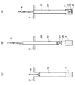
図1は、本発明の一実施形態に係る杭の側面図および断面図である。
杭1は、建物の基礎2を支持するものであり、基礎2の下面から下方に向かって鉛直方向に延びている。
杭1は、地盤3に掘削された杭穴10と、この杭穴10の先端部分に築造された根固め部12と、杭穴10に挿入された中空の鉄筋コンクリート製の既製杭20と、根固め部12に埋め込まれて定着した支圧プレート30と、既製杭20の内部に挿通されて支圧プレート30に連結される連結部材31と、を備える。
Hereinafter, an embodiment of the present invention will be described with reference to the drawings.
The
The
杭穴10の先端部分(下端部分)は拡底されており、拡底部分11が形成されている。この拡底部分11は、地盤3の支持層に形成されている。
根固め部12は、杭穴10の拡底部分11に充填された根固め液としてのセメントミルクが固化して築造されている。このセメントミルクは、ある程度の強度を安定して得られるものである。これにより、この根固め部12の全体が支持層の中に位置しており、根固め部12の外径は、既製杭20の外径よりも大きくなっている。
The front end portion (lower end portion) of the
The
連結部材31の上端側(基端側)は、緊張力が導入された状態で、プレート32を介して建物の基礎2に定着している。
既製杭20の先端部分は、根固め部12にある程度埋め込まれている。なお、この既製杭20の埋め込み深さは、適宜決定されてよい。
The upper end side (base end side) of the connecting
The tip portion of the ready-made
支圧プレート30は既製杭20の先端面より下側に離隔しており、これにより、根固め部12の一部が既製杭20と支圧プレート30との間に挟まれている。支圧プレート30は、円盤状であり、この支圧プレート30の外径は、既製杭20の外径より大きくなっている。なお、この支圧プレート30の外形寸法は、想定される引抜き力に応じて適宜決定されてよい。
連結部材31の材質および断面積は、伝達する引抜き力の大きさと既製杭20との軸剛性とを考慮して、適宜決定されてよい。
The
The material and the cross-sectional area of the connecting
以上の杭1は、以下の手順で構築される。
まず、地上にて既製杭20を現場に搬入し、この既製杭20の先端側に支圧プレート30を配置し、さらに、連結部材31を既製杭20に挿通して支圧プレート30に連結しておく。このようにして、既製杭20、支圧プレート30、および連結部材31を一体化させておく。
The
First, the ready-made
その後、図2(a)に示すように、杭打ち機40により、先端部分に拡底部分11が形成された杭穴10を形成する。その後、杭打ち機40の掘削ドリルの先端からセメントミルクを吐出して拡底部分11にセメントミルクを充填し、掘削ドリルを上下させて良く撹拌する。その後、掘削ドリルを引き上げながら、掘削ドリルの先端から杭周充填液を吐出して、杭穴10内に充填していく。
Then, as shown to Fig.2 (a), the
続いて、図2(b)に示すように、クレーン41により、地組みした既製杭20を杭穴10に挿入し、地組みした既製杭20の支圧プレート30が拡底部分11の内部に位置するようにする。また、既製杭20を杭穴10に挿入することにより、少なくとも既製杭20の周囲には杭周充填液が充填される。
Subsequently, as shown in FIG. 2 (b), the
その後、セメントミルクが固化して根固め部12が築造されると、図2(c)に示すように、この根固め部12に支圧プレート30が埋め込まれることになる。また、既製杭20の周囲の杭周充填液が固化して、既製杭20が地盤3に定着する。
その後、基礎2を構築し、連結部材31に緊張力を導入して、この緊張力を導入した状態で連結部材31の上端部分を基礎2に定着させる。
Then, when cement milk solidifies and the
Thereafter, the
本実施形態によれば、以下のような効果がある。
(1)既製杭20の先端より下側の根固め部12内に支圧プレート30を配置し、この支圧プレート30に連結部材31を連結した。ここで、支圧プレート30を既製杭20の先端面より下側に離隔して配置したので、根固め部12の一部が既製杭20と支圧プレート30との間に挟まれ、引抜き力に対して根固め部12のせん断抵抗を利用できる。また、従来のように先端にプレートを固定した場合に比べて、プレートがより根固め部12の底に近くなり、連結部材31に作用する引張力が、根固め部12のより深い位置から上方にコーン状に広がって根固め部12の周辺まで確実に伝達されるので、根固め部の引抜き抵抗能力を最大限に活用できる。
よって、杭1に作用する引抜き力を、既製杭20の周面摩擦による抵抗と、これと並列的に機能する連結部材31および支圧プレート30を介した根固め部12による抵抗と、で負担するから、高い引抜き耐力を確実に得ることができる。
According to this embodiment, there are the following effects.
(1) The bearing
Therefore, the pulling force acting on the
(2)連結部材31に緊張力を導入したので、小さな浮上がり変形に対しても根固め部12が有効に機能して、既製杭20の周面摩擦力と相乗的に抵抗するので、引抜き耐力をさらに向上できる。
(2) Since a tension force is introduced into the connecting
(3)根固め部12の全体を地盤3の支持層の中に位置させたので、根固め部12がより強固に地盤3に定着するので、引抜き耐力をさらに向上できる。
(3) Since the entire
(4)支圧プレート30を円盤状とし、この支圧プレート30の外径を既製杭20の外径より大きくしたので、連結部材31に作用する引張力が根固め部12の周辺までより確実に伝達されるようになり、引抜き耐力をさらに向上できる。
(4) Since the bearing
なお、本発明は前記実施形態に限定されるものではなく、本発明の目的を達成できる範囲での変形、改良等は本発明に含まれるものである。
例えば、本実施形態では既製杭20を鉄筋コンクリート造としたが、これに限らず、既製杭を鋼管杭としてもよい。
また、本実施形態では、連結部材31の上端側を基礎2に定着したが、これに限らない。例えば鋼管杭など、既製杭が十分な引き抜き耐力を有している場合には、図3に示すように、連結部材31Aの上端側を既製杭20の杭体に連結してもよい。
It should be noted that the present invention is not limited to the above-described embodiment, and modifications, improvements, etc. within a scope that can achieve the object of the present invention are included in the present invention.
For example, although the ready-made
Moreover, in this embodiment, although the upper end side of the
また、本実施形態では、拡底部分11にセメントミルクを充填して、固化したセメントミルクで根固め部12を築造したが、これに限らない。例えば、掘削ドリルの先端からセメントミルクを吐出して、吐出したセメントミルクと掘削した土とを攪拌してソイルセメントとし、固化したソイルセメントを根固め部としてもよい。
In this embodiment, cemented milk is filled in the expanded
1、1A…杭
2…基礎
3…地盤
10…杭穴
11…拡底部分
12…根固め部
20…既製杭
30…支圧プレート
31、31A…連結部材
32…プレート
40…杭打ち機
41…クレーン
DESCRIPTION OF
Claims (2)
地盤に掘削された杭穴と、当該杭穴の先端部分に充填された根固め液が固化して築造された根固め部と、前記杭穴に挿入された中空の既製杭と、前記根固め部に埋め込まれて前記既製杭の先端面より下側に離隔して配置されたプレートと、下端側を前記プレートに連結されるとともに、上端側を前記既製杭の杭体に定着させる緊張力が導入された連結部材と、を備え、
前記根固め部の外径は前記既製杭の外径より大きく、該根固め部は前記杭穴の拡底部分に形成されており、
前記プレートの外径は、前記既製杭の外径より大きいことを特徴とする杭構造。 A pile structure that supports the structure,
A pile hole excavated in the ground, a root-solidified portion formed by solidifying a root-solidifying liquid filled in a tip portion of the pile-hole, a hollow ready-made pile inserted into the pile-hole, and the root-solidified a plate which is spaced below the front end surface of the prefabricated pile is embedded in part, tension is to fix Rutotomoni is connected to the lower end to the plate, the upper side pile body of the prefabricated pile An introduced connecting member,
The outer diameter of the root consolidation part is larger than the outer diameter of the ready-made pile, and the root consolidation part is formed in the expanded bottom portion of the pile hole ,
A pile structure characterized in that an outer diameter of the plate is larger than an outer diameter of the ready-made pile.
地盤に掘削された杭穴と、当該杭穴の先端部分に充填された根固め液が固化して築造された根固め部と、前記杭穴に挿入された中空の既製杭と、前記根固め部に埋め込まれて前記既製杭の先端面より下側に離隔して配置されたプレートと、下端側を前記プレートに連結されるとともに、上端側は前記既製杭の内部を挿通させて、該既製杭の上端側に設けられた基礎に定着させる緊張力が導入された連結部材と、を備え、
前記根固め部の外径は前記既製杭の外径より大きく、該根固め部は前記杭穴の拡底部分に形成されおり、
前記プレートの外径は、前記既製杭の外径より大きいことを特徴とする杭構造。
A pile structure that supports the structure,
A pile hole excavated in the ground, a root-solidified portion formed by solidifying a root-solidifying liquid filled in a tip portion of the pile-hole, a hollow ready-made pile inserted into the pile-hole, and the root-solidified a plate which is spaced below the front end surface of the prefabricated pile is embedded in part, by Rutotomoni coupled the lower end to the plate, the upper side is inserted inside of the prefabricated pile, the A connecting member introduced with a tension force to be fixed to the foundation provided on the upper end side of the ready-made pile ,
The outer diameter of the root consolidation part is larger than the outer diameter of the ready-made pile, and the root consolidation part is formed in the expanded bottom portion of the pile hole ,
A pile structure characterized in that an outer diameter of the plate is larger than an outer diameter of the ready-made pile.
Priority Applications (1)
| Application Number | Priority Date | Filing Date | Title |
|---|---|---|---|
| JP2011171631A JP5684069B2 (en) | 2011-08-05 | 2011-08-05 | Pile structure |
Applications Claiming Priority (1)
| Application Number | Priority Date | Filing Date | Title |
|---|---|---|---|
| JP2011171631A JP5684069B2 (en) | 2011-08-05 | 2011-08-05 | Pile structure |
Publications (2)
| Publication Number | Publication Date |
|---|---|
| JP2013036188A JP2013036188A (en) | 2013-02-21 |
| JP5684069B2 true JP5684069B2 (en) | 2015-03-11 |
Family
ID=47886044
Family Applications (1)
| Application Number | Title | Priority Date | Filing Date |
|---|---|---|---|
| JP2011171631A Expired - Fee Related JP5684069B2 (en) | 2011-08-05 | 2011-08-05 | Pile structure |
Country Status (1)
| Country | Link |
|---|---|
| JP (1) | JP5684069B2 (en) |
Cited By (1)
| Publication number | Priority date | Publication date | Assignee | Title |
|---|---|---|---|---|
| CN111021395A (en) * | 2019-12-26 | 2020-04-17 | 四川电力设计咨询有限责任公司 | Composite foundation suitable for upper-soil-lower-rock stratum structure |
Families Citing this family (1)
| Publication number | Priority date | Publication date | Assignee | Title |
|---|---|---|---|---|
| ES2552588B1 (en) * | 2014-05-29 | 2016-09-08 | 2Pe Pilotes, S.L. | Device for anchoring a deep support for a foundation and procedure for said anchor |
Family Cites Families (3)
| Publication number | Priority date | Publication date | Assignee | Title |
|---|---|---|---|---|
| JPS62268423A (en) * | 1986-05-16 | 1987-11-21 | Kajima Corp | Construction work of underground pile used in common for earth anchor |
| JPH05171638A (en) * | 1991-12-19 | 1993-07-09 | Taisei Corp | Construction method of pile used as drawing yield strength |
| US7390144B2 (en) * | 2006-02-02 | 2008-06-24 | Nova Group Inc. | Pre-cast/pre-stressed concrete and steel pile and method for installation |
-
2011
- 2011-08-05 JP JP2011171631A patent/JP5684069B2/en not_active Expired - Fee Related
Cited By (1)
| Publication number | Priority date | Publication date | Assignee | Title |
|---|---|---|---|---|
| CN111021395A (en) * | 2019-12-26 | 2020-04-17 | 四川电力设计咨询有限责任公司 | Composite foundation suitable for upper-soil-lower-rock stratum structure |
Also Published As
| Publication number | Publication date |
|---|---|
| JP2013036188A (en) | 2013-02-21 |
Similar Documents
| Publication | Publication Date | Title |
|---|---|---|
| KR101080654B1 (en) | Construction method of Combined micro-pile with existing structure | |
| JP6021993B1 (en) | Rigid connection structure of lower end of support and concrete pile | |
| JP5259510B2 (en) | Retaining wall and its construction method | |
| JP5919675B2 (en) | Composite foundation pile and construction method of composite foundation pile | |
| JP2011236705A (en) | Foundation structure of structure and method of constructing the same | |
| JP5684069B2 (en) | Pile structure | |
| KR20120102480A (en) | Phc pile with improved end bearing capacity and piling method of phc pile using the same | |
| JP2005213904A (en) | Bearing capacity increasing method, construction method of sheet pile foundation, sheet pile foundation and bridge | |
| JP4181192B2 (en) | Ground anchor and ground anchor method | |
| JPH0547685B2 (en) | ||
| JP3185440U (en) | Solar panel installation structure | |
| JP2019218795A (en) | Joint structure of foundation pile and foundation slab | |
| JP6461690B2 (en) | Foundation structure and foundation construction method | |
| JP2023001572A (en) | Pile foundation, and design method of the same | |
| WO2012114529A1 (en) | Method for reinforcing piling, and piling | |
| KR101398687B1 (en) | Micro pile with improved end bearing capacity and its construction methods thereof | |
| JP4762618B2 (en) | Pile foundation structure and construction method | |
| KR20100110224A (en) | Precast pile | |
| KR101695720B1 (en) | A based pile tip connected type based pile and construction method therefor | |
| KR101663174B1 (en) | A based pile with based pile tip and construction method therefor | |
| JP7475316B2 (en) | Ground reinforcement structure and ground reinforcement method | |
| JP2020066875A (en) | Foundation pile, foundation structure, structural body, and installation method of foundation pile | |
| JP7341579B1 (en) | Reinforcement method for retaining walls | |
| JP5543286B2 (en) | Pile reinforcement method and pile | |
| CN211872979U (en) | Multi-row ultra-deep oblique composite anchor rod pile for narrow space |
Legal Events
| Date | Code | Title | Description |
|---|---|---|---|
| A621 | Written request for application examination |
Free format text: JAPANESE INTERMEDIATE CODE: A621 Effective date: 20131113 |
|
| A977 | Report on retrieval |
Free format text: JAPANESE INTERMEDIATE CODE: A971007 Effective date: 20140604 |
|
| A131 | Notification of reasons for refusal |
Free format text: JAPANESE INTERMEDIATE CODE: A131 Effective date: 20140618 |
|
| A521 | Written amendment |
Free format text: JAPANESE INTERMEDIATE CODE: A523 Effective date: 20140806 |
|
| A02 | Decision of refusal |
Free format text: JAPANESE INTERMEDIATE CODE: A02 Effective date: 20140826 |
|
| A521 | Written amendment |
Free format text: JAPANESE INTERMEDIATE CODE: A523 Effective date: 20141120 |
|
| A911 | Transfer to examiner for re-examination before appeal (zenchi) |
Free format text: JAPANESE INTERMEDIATE CODE: A911 Effective date: 20141128 |
|
| TRDD | Decision of grant or rejection written | ||
| A01 | Written decision to grant a patent or to grant a registration (utility model) |
Free format text: JAPANESE INTERMEDIATE CODE: A01 Effective date: 20150106 |
|
| A61 | First payment of annual fees (during grant procedure) |
Free format text: JAPANESE INTERMEDIATE CODE: A61 Effective date: 20150114 |
|
| R150 | Certificate of patent or registration of utility model |
Ref document number: 5684069 Country of ref document: JP Free format text: JAPANESE INTERMEDIATE CODE: R150 |
|
| LAPS | Cancellation because of no payment of annual fees |