JP5683247B2 - Virus inactivation apparatus, method thereof and air conditioner using the same - Google Patents
Virus inactivation apparatus, method thereof and air conditioner using the same Download PDFInfo
- Publication number
- JP5683247B2 JP5683247B2 JP2010278495A JP2010278495A JP5683247B2 JP 5683247 B2 JP5683247 B2 JP 5683247B2 JP 2010278495 A JP2010278495 A JP 2010278495A JP 2010278495 A JP2010278495 A JP 2010278495A JP 5683247 B2 JP5683247 B2 JP 5683247B2
- Authority
- JP
- Japan
- Prior art keywords
- virus
- electrode
- air
- viruses
- floating
- Prior art date
- Legal status (The legal status is an assumption and is not a legal conclusion. Google has not performed a legal analysis and makes no representation as to the accuracy of the status listed.)
- Active
Links
Images


Landscapes
- Air Filters, Heat-Exchange Apparatuses, And Housings Of Air-Conditioning Units (AREA)
- Disinfection, Sterilisation Or Deodorisation Of Air (AREA)
Description
本発明は、空間に浮遊しているウイルスを捕捉せず、放電場を通過する際に、不活化させるウイルスの不活化装置、その方法、およびそれを用いた空調機に関するものである。 The present invention relates to a virus inactivation apparatus that inactivates a virus floating in space without being captured and passes through a discharge field, a method thereof, and an air conditioner using the same.
従来から、空間に浮遊している微生物やウイルスを除去する浮遊微生物・浮遊ウイルス除去装置が存在している。そのようなものとして、風上側から、コロナ荷電部、高圧電極、フィルター、フィルターに接した電極の順で配置され、作動の間の電荷蓄積の影響を打ち消して、長い寿命全体にわたって高い除去効力を提供できるようにした浮遊微生物・浮遊ウイルス除去装置が開示されている(たとえば、特許文献1参照)。
また、空間に飛散している化学物質等のガスを浄化する装置として、化学物質を吸着するハニカム構造の吸着剤と、吸着剤に密接して設けられた給電極と、放電電極とを備え、ガス状の化学物質を効果的に捕捉し、分解できるガス浄化装置が開示されている(たとえば、特許文献2参照)。
Conventionally, there are floating microorganism / floating virus removal devices that remove microorganisms and viruses floating in the space. As such, from the windward side, the corona charging section, the high voltage electrode, the filter, and the electrode in contact with the filter are arranged in this order, counteracting the effects of charge accumulation during operation and providing high removal efficacy over a long lifetime. An apparatus for removing airborne microorganisms / airborne viruses that can be provided is disclosed (for example, see Patent Document 1).
In addition, as a device for purifying gas such as chemical substances scattered in the space, it comprises a honeycomb structure adsorbent that adsorbs chemical substances, a supply electrode provided in close contact with the adsorbent, and a discharge electrode, A gas purification device that can effectively capture and decompose gaseous chemical substances has been disclosed (see, for example, Patent Document 2).
特許文献1に記載のような浮遊微生物・浮遊ウイルス除去装置にあっては、浮遊微生物・浮遊ウイルスをフィルターに付着させ、捕捉することにより、空間中から、除去している。そのため、特許文献1に記載のような浮遊微生物・浮遊ウイルス除去装置では、ウイルスを捕捉し続けると、フィルターでの圧力損失があがり、エネルギー消費量の増大、騒音が発生し、また、ウイルス捕捉効果が低下してしまうという問題点があった。また、特許文献1に記載のような浮遊微生物・浮遊ウイルス除去装置では、フィルターで捕捉した微生物やウイルスの再飛散、またフィルター上で増殖するのを防止するためには、フィルターを清浄化する等のメンテナンス作業を行う必要があるという問題点もあった。
特許文献2に記載のようなガス浄化装置にあっては、ガス(空気)に対して、プラズマ放電のみしか行っていないため、化学物質を吸着し、効果的に分解することができるが、ウイルスを捕捉することができないことはもちろんのこと、一過性でウイルスを不活化することはできないという問題点があった。
In the floating microbe / floating virus removal apparatus as described in
In the gas purification apparatus as described in
本発明は、上記のような問題を解決するためになされたもので、ウイルスを捕捉することなく、加熱空間および電極間での放電空間を通過させることにより、一過性で、効率的にウイルスを不活化するとともに、ウイルス不活化工程において、圧力損失がなく、静音なウイルス不活化装置、その方法、およびそれを用いた空調機を提供することを目的としている。 The present invention has been made in order to solve the above-described problems. By passing the heating space and the discharge space between the electrodes without trapping the virus, the virus is transiently and efficiently transmitted. In addition, in the virus inactivation step, there is no pressure loss and a silent virus inactivation device, a method thereof, and an air conditioner using the same are provided.
本発明に係るウイルス不活化装置は、空気中に浮遊しているウイルスを捕捉することなく不活化する装置であって、空気と共に浮遊ウイルスを風路に取り込む送風機と、浮遊ウイルスが通過する風路に配置され、浮遊ウイルスを加熱処理する加熱装置と、浮遊ウイルスをプラズマ処理する高圧電極、およびこの高圧電極に対向して設置された接地電極と、正極と負極とで構成された第2電極と、前記高圧電極に高電圧を印加するために接続された高圧電源と、を備え、前記加熱装置による空気加熱温度を30℃以上とするとともに、前記風路の風上側から順に、前記加熱装置と、前記高圧電極と、前記接地電極と、前記第2電極と、を配置したものである。 The virus inactivation apparatus according to the present invention is an apparatus that inactivates without trapping viruses floating in the air, and a blower that takes in the floating viruses together with air into the air path, and an air path through which the floating viruses pass disposed, the heating apparatus for heating a floating virus, high-voltage electrode to the floating virus plasma treatment, and a ground electrode disposed to face the high voltage electrode, a second electrode composed of a positive electrode and a negative electrode A high-voltage power source connected to apply a high voltage to the high-voltage electrode, the air heating temperature by the heating device is 30 ° C. or more, and in order from the windward side of the air passage, The high-voltage electrode, the ground electrode, and the second electrode are arranged.
また、本発明に係るウイルス不活化方法は、空気中に浮遊しているウイルスを捕捉することなく不活化する方法であって、空気と共に浮遊ウイルスを風路に取り込む工程と、前記風路に取り込んだ前記空気と前記浮遊ウイルスに対し、30℃以上に加熱処理を行う工程と、プラズマ処理を行う工程と、を順に有し、前記プラズマ処理の後に、浮遊ウイルスを不活化させる少なくとも銀、銅、亜鉛のうちのいずれか1つの金属イオンを浮遊ウイルスに付着させる工程を含むものである。 Further, the virus inactivation method according to the present invention is a method for inactivation without trapping viruses floating in the air, the step of taking the floating viruses together with air into the air passage, and the incorporation into the air passage I to the floating viruses and the air, and performing heat treatment to 30 ° C. or higher, possess a step of performing a plasma treatment, in sequence, after the plasma treatment, at least silver, copper to inactivate floating viruses, The method includes a step of attaching any one metal ion of zinc to the suspended virus .
本発明において、ウイルスとは、生物に寄生し、生きた細胞内でのみ増殖する微粒子をいう。大きさは約20〜260ミリミクロンであり、化学的には核蛋白質を本体とし、大形のものは脂質や多糖類をも含む。核蛋白質中の核酸は、増殖に際して生物の遺伝子と同じような働きをする。
また、ウイルスの不活化とは、ウイルスの感染能力を失活させることをいう。
また、風路とは、管状の風路のみを意味するのではなく、筐体の中を通る場合などを含めて、広く風の流れとなる通路のことである。
In the present invention, a virus refers to a fine particle that is parasitic on a living organism and grows only in living cells. The size is about 20 to 260 millimicrons, and it is chemically composed of nucleoprotein as a main body, and large ones also contain lipids and polysaccharides. Nucleic acids in nucleoprotein function in a manner similar to organismal genes during growth.
Moreover, inactivation of a virus means deactivating the infectivity of a virus.
The air passage does not mean only a tubular air passage, but a passage through which air flows widely, including when passing through a housing.
本発明に係るウイルス不活化装置及びその方法によれば、空気中に浮遊しているウイルスを捕捉することなく、一過性で、効率的にウイルスを不活化するとともに、ウイルス不活化工程において、圧力損失がなく、静音なウイルスの不活化を行うことができる。 According to the virus inactivation apparatus and the method thereof according to the present invention, transiently and efficiently inactivating viruses without capturing viruses floating in the air, and in the virus inactivation step, There is no pressure loss, and silent virus inactivation can be performed.
以下、本発明の実施の形態を図面に基づいて説明する。 Hereinafter, embodiments of the present invention will be described with reference to the drawings.
実施の形態1.
図1は、本発明の実施の形態1に係るウイルスの不活化装置(以下、装置100と称する)の概略構成を示す縦断面図である。図1に基づいて、装置100の構成及び動作について説明する。なお、図1を含め、以下の図面では各構成部材の大きさの関係が実際のものとは異なる場合がある。また、図1では、空気の流れを矢印で示している。
装置100は、空間に浮遊しているウイルスを捕捉せず、一過性で、効率的にウイルスを不活化するものである。装置100は、風路9を形成する筐体(以下、風路筐体と称する)10の内部に、風上(上流)側から、送風機1、加熱装置2、高圧電極3、接地電極4が順に配置されて構成されている。
FIG. 1 is a longitudinal sectional view showing a schematic configuration of a virus inactivation apparatus (hereinafter, referred to as apparatus 100) according to
The
送風機1は、風路筐体10内に空気を取り込み送り出すものである。
加熱部での加熱手段としては、例えば、板状、ロット状、あるいはワイヤー状の電気ヒーター等からなる発熱体を使用し、該発熱体を風路9の外周部に密着させて設置すればよい。かかる発熱体は、空気を加熱できるものであればよく、特に電気ヒーターに限られるものではない。
The
As a heating means in the heating unit, for example, a heating element composed of a plate-like, lot-like, or wire-like electric heater is used, and the heating element may be installed in close contact with the outer peripheral portion of the
高圧電極3は、たとえば線径0.1mm〜0.3mm程度の細線が多数張られた電極で構成され、接続されている可変型の高電圧電源5から直流高電圧が印加されるようになっている。
接地電極4は、たとえば金属メッシュ等からなる電極で構成され、アースに接続されるようになっている。高圧電極3及び接地電極4でプラズマ部を構成している。なお、以下の実施の形態では、接地電極であるとして説明するが、高圧電極3と接地電極4との間に電圧が印加されればよく、接地電極4が必ずしも接地されて使用されていなくてもよい。また、高圧電極3を断面積が0.1mm×0.5mmの長方形又はその類似形状のリボン(厚み0.1mm)で構成しても同様の効果が得られる。この場合、断面積が0.1mm×0.1mmとなる面を接地電極4に向けるようにした方が効率的に荷電でき、また、放電時のスパッターによる電極磨耗による断線の影響を小さくできる効果がある。
The high-
The ground electrode 4 is composed of, for example, an electrode made of a metal mesh or the like, and is connected to the ground. The
次に、装置100の動作について説明する。
図2は、装置100が実行するウイルス不活化方法の流れを示すフローチャートである。装置100の特徴は、ウイルスを加熱する部分と、ウイルスに高電圧を印加する部分とを兼ね備えた点である。すなわち、ウイルスに加熱処理、プラズマ処理を行うことにより、ウイルスを効率的に不活化できるようになっている。
Next, the operation of the
FIG. 2 is a flowchart showing the flow of the virus inactivation method executed by the
装置100が運転を開始すると、まず送風機1が稼動する。そして、それと同時に加熱装置2が稼動する(S1)。高電圧電極付近の温度を図示省略の制御基板等に設けられている温度判定部で計測される。計測された温度は、温度判定部によって予め設定されている設定温度と比較される(S2)。そして、問題がなければ次の工程に移る。
測定された温度が設定温度値よりも低ければ、加熱装置2によりさらに加熱する。このようにして、浮遊しているウイルスを常時効率よく加熱されていることを確認する。
When the
If the measured temperature is lower than the set temperature value, the
次に、放電によるウイルス不活化工程が開始される(S3)。すなわち、高圧電極3に可変型高電圧電源5から高電圧が印加される(S4)。これにより、高圧電極3と接地電極4との間で放電が起こり(S5)、放電電流が接地電極4に流れる。ここで、接地電極4に流れる電流は、図示省略の制御基板等に設けられている電流判定部で計測される。計測された電流値は、電流判定部によって予め設定されている設定電流値と比較される。そして、問題がなければそのまま不活化処理工程が開始される。
Next, a virus inactivation step by discharge is started (S3). That is, a high voltage is applied to the
測定された電流値が設定電流値よりも低ければ、高圧電極3に印加される電圧が高くされ、測定された電流値が設定電流値よりも高ければ、高圧電極3に印加される電圧が低くされる。このようにして、ウイルスを常時効率よく不活化処理されていることを確認する。放電によるウイルス不活化工程が開始すると、タイマーが作動し、これら一連の工程における処理時間(工程の運転時間)が計測される(S6)。
これら一連の工程における処理時間が設定時間に達すると、高圧電極3への高電圧印加が停止され、不活化工程は終了する(S7)。
その後、再びウイルス不活化が必要になれば、加熱工程が開始され、上記の運転が繰り返されることになる。
If the measured current value is lower than the set current value, the voltage applied to the
When the processing time in these series of steps reaches the set time, the high voltage application to the
Thereafter, when virus inactivation becomes necessary again, the heating step is started, and the above operation is repeated.
以上のように、装置100では、ウイルスを加熱する工程と、ウイルスに高電圧を印加する工程を有するようにしたことにより、浮遊ウイルスを捕捉することなく、一過性でウイルスを不活化することができる。また、ウイルス不活化装置がウイルス等を捕捉することがないため、常時衛生的に保持することができ、かつ、圧力損失が無く静音にウイルスを不活化することができる。
As described above, the
次に、装置100の特徴事項である加熱処理工程とプラズマ処理工程とによるウイルスの不活化に関して説明する。ウイルスの不活化の試験においては、すべて大腸菌ファージφX174を供試ウイルスとして用いている。
Next, virus inactivation by the heat treatment step and the plasma treatment step, which are characteristic items of the
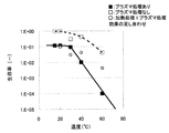
図3は、各温度でのプラズマ処理によるウイルスの生存率を示す。横軸に温度、縦軸に生存率を示す。なお、比較対象として、プラズマ処理を行っていない場合におけるウイルス生存率も記載する。プラズマ処理を行わなかった場合、温度が15℃〜40℃程度までウイルス生存率は30〜40%以上でほとんどウイルスが不活化していない。その一方で、プラズマ処理を行った場合、温度が30℃までは、生存率が10%であったのに対し、温度が30℃より高くなると、急激に生存率が低下し、40℃では9.8×10⁻³、60℃で9.9×10⁻⁵となった。 FIG. 3 shows virus viability by plasma treatment at each temperature. The horizontal axis shows temperature, and the vertical axis shows survival rate. As a comparison object, the virus survival rate when the plasma treatment is not performed is also described. When the plasma treatment was not performed, the virus survival rate was 30 to 40% or higher until the temperature was about 15 to 40 ° C., and the virus was hardly inactivated. On the other hand, when the plasma treatment was performed, the survival rate was 10% until the temperature was 30 ° C., whereas when the temperature was higher than 30 ° C., the survival rate rapidly decreased, and at 40 ° C., the survival rate was 9%. 8 × 10 −3 , and 9.9 × 10 −5 at 60 ° C.
プラズマ処理を行わなかった場合に生存率が90%以上となり、温度により不活化していない条件といえる15℃、20℃において、プラズマ処理を行った場合には、生存率が10%まで低下していることから、このウイルス生存率の低下は、プラズマ処理による不活化効果であるといえる。 When plasma treatment is not performed, the survival rate is 90% or more, and when plasma treatment is performed at 15 ° C. and 20 ° C., which are not inactivated by temperature, the survival rate decreases to 10%. Therefore, it can be said that this decrease in the virus survival rate is an inactivation effect by plasma treatment.
図4は、各温度でのプラズマ処理によるウイルスの生存率に加え、各温度での加熱処理による不活化効果とプラズマ処理による不活化効果(上記より生存率が10%になると仮定したときの効果)を単純に足し合わせたプロットを追記したグラフである。横軸に温度、縦軸に生存率を示す。
図4からわかるように温度が30℃以上になると、単純に加熱処理とプラズマ処理の効果を足し合わせた生存率よりも、実際に加熱処理と、プラズマ処理を行った処理によるウイルス生存率のほうが低く、ウイルス不活化効果が著しく増大していることがわかる。
FIG. 4 shows the inactivation effect by the heat treatment at each temperature and the inactivation effect by the plasma treatment (effect when the survival rate is assumed to be 10% based on the above) in addition to the virus survival rate by the plasma treatment at each temperature. ) Is a graph in which a plot is simply added. The horizontal axis shows temperature, and the vertical axis shows survival rate.
As can be seen from FIG. 4, when the temperature is 30 ° C. or higher, the virus survival rate by the heat treatment and the plasma treatment is actually higher than the survival rate obtained by simply adding the effects of the heat treatment and the plasma treatment. It can be seen that the virus inactivation effect is significantly increased.
プラズマ処理工程では、空気中に酸素や水が存在するため、電子や、水素イオン(H+)、酸素イオン(O2 -)等の正負のイオンが共存した状態となる。また、負イオンが水と反応すると、ヒドロキシルラジカル等の活性度の高いラジカルが生成する。それらが、たんぱく質とDNAやRNA等の核酸等から構成されるウイルスに直接アタックし、物理的に損傷を与える。その損傷効果が高ければ、ウイルスは不活化する。しかし、ウイルスのような微生物は自己再生機能を有しているため、その損傷効果が少なければ、自己修復し、その結果、活性を取り戻し、もとの感染可能な状態に戻る。 In the plasma treatment process, oxygen and water are present in the air, so that electrons and positive and negative ions such as hydrogen ions (H + ) and oxygen ions (O 2 − ) coexist. Further, when negative ions react with water, radicals with high activity such as hydroxyl radicals are generated. They directly attack and physically damage viruses composed of proteins and nucleic acids such as DNA and RNA. If the damage effect is high, the virus is inactivated. However, since microorganisms such as viruses have a self-regenerating function, if their damage effect is small, they self-repair, and as a result, regain activity and return to the original infectable state.
微生物の自己再生機能は、ある温度以上の高温に置かれると、低下することがわかっている。自己再生機能が低下すると、本来であれば、活性を取り戻し、感染可能な状態に戻るウイルスが、そのまま不活化してしまう。 It has been found that the self-renewal function of microorganisms decreases when placed at a high temperature above a certain temperature. When the self-regenerating function is lowered, the virus that regains its activity and returns to an infectable state is inactivated as it is.
本工程においては、加熱工程によりウイルスの自己再生機能を低下させ、その上でプラズマ処理を行う工程となっている。そのため、これらを総合すると、加熱工程およびプラズマ工程を組み合わせることにより、各工程でウイルスが不活化する作用に加え、各工程だけでは自己再生機能により感染力を取り戻すウイルスまでもが各工程を組み合わせることで不活化することにより、相乗的にウイルスを不活化させることができたと考えられる。 In this process, the self-regeneration function of the virus is reduced by the heating process, and the plasma treatment is performed thereon. Therefore, when these are combined, by combining the heating process and the plasma process, in addition to the action of inactivating the virus in each process, each process also combines the virus to regain infectivity by the self-regenerative function in each process alone. It is considered that the virus was able to be synergistically inactivated by inactivation.
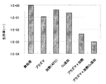
図5は、加熱温度として40℃に設定した場合において、加熱処理もプラズマ処理も行わない場合(無処理)、プラズマ処理のみ行った場合、加熱のみ行った場合、プラズマ処理と加熱処理の両者を行った場合のウイルスの生存率を調べた結果を示したものである。 FIG. 5 shows that when the heating temperature is set to 40 ° C., neither heat treatment nor plasma treatment is performed (no treatment), only plasma treatment is performed, only heating is performed, both plasma treatment and heat treatment are performed. It shows the result of examining the survival rate of the virus when it is performed.
図5に示すように、ウイルス生存率は、無処理の場合の95%に対し、プラズマ処理だけでは10%、加熱処理だけでは40%、プラズマ処理と加熱処理の両者を行った場合には0.4%となり、プラズマ処理と加熱処理の両者を行うことにより、相乗的にウイルス不活化効果が増大することがわかった。また、言い換えれば、加熱処理、プラズマ処理、そして両者の複合効果により、ウイルス不活化効果が増大したといえる。 As shown in FIG. 5, the virus survival rate is 95% for the case of no treatment, 10% for the plasma treatment alone, 40% for the heat treatment alone, and 0 for both the plasma treatment and the heat treatment. It was found that the virus inactivation effect increased synergistically by performing both plasma treatment and heat treatment. In other words, it can be said that the virus inactivation effect is increased by the heat treatment, the plasma treatment, and the combined effect of both.
以上のことから、ウイルス不活化効果を高めるためには、加熱処理とプラズマ処理の両者を行うことが必要であることがわかった。 From the above, it was found that in order to enhance the virus inactivating effect, it is necessary to perform both heat treatment and plasma treatment.
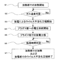
次に、加熱処理とプラズマ処理の工程の順番がウイルスの不活化に与える影響を説明する。
図6は、ウイルスに対し、加熱処理を行った後プラズマ処理を行った場合と、プラズマ処理を行った後、加熱処理を行った場合のウイルス生存率の比較を行ったグラフである。比較対象として、加熱処理とプラズマ処理単独の効果を足し合わせた結果も記載している。単純に足し合わせた処理の結果であるウイルス生存率は4.14×10⁻²であるのに対し、加熱処理を行った後プラズマ処理を行った場合のウイルス生存率は9.81×10⁻³、プラズマ処理を行った後加熱処理を行った場合のウイルス生存率は2.91×10⁻²であった。
Next, the influence of the order of the heat treatment and plasma treatment steps on virus inactivation will be described.
FIG. 6 is a graph comparing the virus viability when the virus is subjected to the heat treatment after the heat treatment, and when the virus is subjected to the heat treatment after the plasma treatment. As a comparison object, the result of adding the effects of heat treatment and plasma treatment alone is also described. Virus survival is the result of simply adding the combined treatment whereas a 4.14 × 10 -2, virus survival in the case of performing plasma treatment after the heat treatment is 9.81 × 10 - 3. When the heat treatment was performed after the plasma treatment, the virus survival rate was 2.91 × 10 −2 .
このことから、加熱処理、プラズマ処理のどちらの工程を先にしても、単なる足し合わせの効果よりもウイルス不活化効果が高いことがわかった。また、それと同時に、加熱処理後プラズマ処理のほうが、プラズマ処理後加熱処理よりもウイルス生存率が低いことから、加熱処理後プラズマ処理のほうが、より相乗的にウイルスを不活化することができることがわかった。 From this, it was found that the virus inactivating effect was higher than the mere addition effect when either the heat treatment or the plasma treatment was performed first. At the same time, the plasma treatment after the heat treatment has a lower virus survival rate than the heat treatment after the plasma treatment, and thus it can be seen that the plasma treatment after the heat treatment can inactivate the virus more synergistically. It was.
以上のことより、本装置においては、加熱部、プラズマ部の処理工程順はどちらでもウイルス不活化効果が高められるが、最も効率よくウイルスを不活化するには、加熱部の後に、プラズマ部を設けるのがよいことがわかった。 From the above, in this apparatus, the virus inactivation effect is enhanced in either order of the processing steps of the heating unit and the plasma unit. However, in order to inactivate the virus most efficiently, the plasma unit is placed after the heating unit. It turned out that it is good to install.
以上のことから、ウイルスに対し、加熱工程の後に、プラズマ処理工程を行うウイルス不活化装置の構造とすることにより、ウイルスを捕捉することなく、一過性で不活化することができるようになる。これにより、装置100では、加熱工程後、ウイルスにプラズマ処理を行うことで、ウイルスを捕捉することなく、一過性で、ウイルスを高効率的に不活化することができ、空気中に浮遊しているウイルスを圧損低下なく、低コスト、静音でウイルスを不活化することが可能となる。
From the above, it becomes possible to temporarily inactivate a virus without capturing the virus by adopting a structure of a virus inactivation apparatus that performs a plasma treatment step after the heating step. . Thereby, in the
なお、実施の形態1では、浮遊微生物を荷電する前に空気中の粗塵を取り除くフィルターを記載していないが、空気が浮遊微生物を荷電する荷電部に流れ込む前に空気中の粗塵を取り除くようなフィルターを備えるようにした方が効率的なウイルス不活化効果が得られることはいうまでもない。
また、実施の形態1では、プラズマ部で荷電されたウイルス粒子は、そのまま荷電を保持したまま、装置を通過してしまう構造となっている。そのため、加熱部、プラズマ部の後段に、中和部を配置し、ウイルス粒子の荷電を電気的に中和する構造を付加してもよい。
Although the filter for removing coarse dust in the air before charging the floating microorganisms is not described in the first embodiment, the dust in the air is removed before the air flows into the charged portion that charges the floating microorganisms. It goes without saying that an efficient virus inactivating effect can be obtained by providing such a filter.
Moreover, in
図7は、実施の形態1のウイルス不活化装置に中和部を追加した構成図である。図に中和部の詳細を示す。中和部には、プラズマ部の放電電極(高圧電極3)と逆電位の中和部電極6、次いで同電位の中和部電極7が配置されている。各中和部電極6、7は、金属メッシュ等からなる電極で構成されている。なお、図7において、8は中和部電極6と中和部電極7との間に所定の電圧を印加するための中和部電圧電源である。
この構成によれば、プラズマ部より浮遊してきた荷電されたウイルス粒子の多くは、逆電位の中和部電極6と接触し、電荷を失い、その後、装置100を通過してしまう。また、仮に逆電位の中和部電極6と接触しなかった場合でも、その後の同電位の中和部電極7により、逆電位の中和部電極6の方向に逆戻りし、その結果、逆電位の中和部電極6と接触し、電荷を失ってしまう。このようにして、ウイルス粒子は、中和部において、電荷を失う構造となっている。
FIG. 7 is a configuration diagram in which a neutralization unit is added to the virus inactivation apparatus of the first embodiment. The details of the neutralization part are shown in the figure. In the neutralization section, a discharge electrode (high voltage electrode 3) in the plasma section and a
According to this configuration, most of the charged virus particles floating from the plasma part come into contact with the neutralizing
また、実施の形態1では、送風機1を風上側に設置し、ウイルス不活化部に空気を押し込む場合について述べたが、送風機を風下側に設置し、ウイルス不活化部から空気を吸い込むようにしても、同様の殺菌効果が得られることはいうまでもない。
Moreover, in
上記実施の形態では、放電電極(高圧電極3)が細線によって構成されている場合(線電極)について示したが、放電電極(高圧電極3)は、針状の突起物を有した針状電極や、ブラシのように金属線を植毛したブラシ状電極を用いるようにしても良い。ただし、針状電極を近づけ過ぎたり、印加電圧をあげすぎると、火花放電が起こり、大量の電流が流れるため、高圧電源に出力電流制御装置を組み込んだり、高圧電源の出力電圧波形をパルス状にすることにより、大電流が流れないようにするような工夫が必要である。 In the above embodiment, the case where the discharge electrode (high voltage electrode 3) is constituted by a thin line (line electrode) is shown, but the discharge electrode (high voltage electrode 3) is a needle electrode having a needle-like projection. Alternatively, a brush-like electrode in which a metal wire is implanted like a brush may be used. However, if the needle electrode is too close or the applied voltage is increased too much, a spark discharge will occur and a large amount of current will flow.Therefore, an output current control device will be incorporated into the high voltage power supply, or the output voltage waveform of the high voltage power supply will be pulsed. Therefore, it is necessary to devise a method for preventing a large current from flowing.
高圧電極3と接地電極4との間で放電させるためには、所定の間隔を設ける必要がある。この間隔が長くなるほど放電開始に必要な放電電圧が高くなるため、高圧電源の付加が増大し、かつ、高圧電極3から装置筐体への異常放電を引き起こす可能性があるため、絶縁対策が必要となる。したがって、高電圧電極と接地電極との間隔はできるだけ短いほうが望ましいが、間隔が短くなると気体の絶縁破壊が生じ、接地電極への火花放電を誘発する。このため、高圧電極3と接地電極4との間の間隔の設定には留意を要する。
In order to discharge between the high-
放電させるために高圧電極3と接地電極4間に高電圧を共有する高圧電源としては、放電を発現させ、電子、イオン、オゾン等の活性種を精製できるものであればよく、印加される電圧波形は、正、あるいは負極性の直流電圧、交流電圧、パルス、短形波(矩形波)等、いずれの形態でもよい。
The high-voltage power source that shares a high voltage between the high-
実施の形態2.
図8は、本発明の実施の形態2に係るウイルス不活化装置(以下、装置100aと称する)の概略構成を示す縦断面図である。図8に基づいて、装置100aの構成及び動作について説明する。なお、実施の形態2では実施の形態1との相違点を中心に説明し、実施の形態1と同一部分には、同一符号を付している。また、図8では、空気の流れを矢印で示している。
FIG. 8 is a longitudinal sectional view showing a schematic configuration of a virus inactivation apparatus (hereinafter referred to as
実施の形態2に係る装置100aは、風路筐体10の内部に、風上(上流)側から、送風機1、加熱装置2、高圧電極(高電圧印加電極)3、高圧電極3に対向した接地電極4、さらに第2電極として、空気の流れに対して平行に、かつ正極と負極が交互に配置させたイオン付着部電極11、12が順に配置されて構成されている。すなわち、装置100aは、高圧電極3、接地電極4のプラズマ部の後段に、第2電極(イオン付着部電極11、12)が構成されている点が、実施の形態1に係る装置100と相違している。なお、図8において、13はイオン付着部電極11、12間に所定の電圧を印加するためのイオン付着部電圧電源である。
The
この第2電極の材料は、銅(Cu)、亜鉛(Zn)、銀(Ag)等、ウイルスを不活化する効果を有する金属を使用し、その表面は、疎水化処理が施されていることを特徴としている。ここで、金属の疎水化処理に関して説明する。
電極表面は、疎水性を有するとともに、金属がむき出しになった状態であることが必要である。そのため、金属を300℃程度の高温で処理するのが望ましい。また、その他の方法で同様の疎水性処理が行えるのであれば、それらの方法を用いてもよい。
The material of the second electrode is a metal having an effect of inactivating viruses, such as copper (Cu), zinc (Zn), silver (Ag), etc., and its surface is subjected to a hydrophobic treatment. It is characterized by. Here, the metal hydrophobization process will be described.
The electrode surface must be hydrophobic and have a bare metal. Therefore, it is desirable to treat the metal at a high temperature of about 300 ° C. In addition, as long as the same hydrophobic treatment can be performed by other methods, those methods may be used.
次に、装置100aの動作について説明する。
図9は、装置100aが実行するウイルス不活化方法の流れを示すフローチャートである。装置100aの特徴は、ウイルスを加熱する部分と、ウイルスに高電圧を印加する部分、更にウイルス粒子にイオンが溶解する部分とを兼ね備えた点である。すなわち、ウイルスに加熱処理、プラズマ処理、金属イオン付着処理を行うことにより、ウイルスを効率的に不活化できるようになっている。
Next, the operation of the
FIG. 9 is a flowchart showing the flow of the virus inactivation method executed by the
装置100aが運転を開始すると、まず送風機1が稼動する。そして、それと同時に加熱装置2が稼動する(S11)。高電圧電極付近の温度を図示省略の制御基板等に設けられている温度判定部で計測される。計測された温度は、温度判定部によって予め設定されている設定温度と比較される(S12)。そして、問題がなければ次の工程に移る。
測定された温度が設定温度値よりも低ければ、加熱装置2によりさらに加熱する。このようにして、浮遊しているウイルスを常時効率よく加熱されていることを確認する。
When the
If the measured temperature is lower than the set temperature value, the
次に、放電によるウイルス不活化工程が開始される(S13)。すなわち、高圧電極3に可変型高電圧電源5から高電圧が印加される(S14)。これにより、高圧電極3と接地電極4との間で放電が起こり(S15)、放電電流が接地電極4に流れる。ここで、接地電極4に流れる電流は、図示省略の制御基板等に設けられている電流判定部で計測される。計測された電流値は、電流判定部によって予め設定されている設定電流値と比較される。そして、問題がなければそのまま不活化処理工程が開始される。
Next, the virus inactivation process by discharge is started (S13). That is, a high voltage is applied to the
測定された電流値が設定電流値よりも低ければ、高圧電極に印加される電圧が高くされ、測定された電流値が設定電流値よりも高ければ、高圧電極に印加される電圧が低くされる。このようにして、ウイルスを常時効率よく不活化処理されていることを確認する。 If the measured current value is lower than the set current value, the voltage applied to the high voltage electrode is increased, and if the measured current value is higher than the set current value, the voltage applied to the high voltage electrode is decreased. In this way, it is confirmed that the virus is always inactivated efficiently.
次に、金属イオン付着によるウイルス不活化工程が開始される(S16)。第2電極(イオン付着部電極11、12)にイオン付着部電圧電源13から電圧が印加される(S17)。これにより、第2電極(イオン付着部電極11、12)の電極それぞれが正極、負極に帯電する(S18)。ここで、第2電極(イオン付着部電極11、12)間に流れる電流は、図示省略の制御基板等に設けられている電流判定部で計測される。計測された電流値は、電流判定部によって予め設定されている設定電流値と比較される。そして、問題がなければそのまま金属イオン付着による不活化処理工程が開始される。
Next, the virus inactivation process by metal ion attachment is started (S16). A voltage is applied from the ion attachment portion
測定された電流値が設定電流値よりも低ければ、第2電極(イオン付着部電極11、12)間に電圧が印加されており、金属イオン付着によるウイルス不活化効果が得られる。測定された電流値が設定電流値よりも高ければ、異常とみなし、電圧印加を中断する。このようにして、ウイルスを常時効率よく不活化処理されていることを確認する。
If the measured current value is lower than the set current value, a voltage is applied between the second electrodes (ion
全ウイルス不活化工程が開始すると、タイマーが作動し、これら一連の工程における処理時間(工程の運転時間)が計測される。
これら一連の工程における処理時間(工程の運転時間)が設定時間に達する(S19)と、高圧電極3への高電圧印加、第2電極(イオン付着部電極11、12)への電圧印加が停止され、不活化工程は終了する(S20)。
その後、再びウイルス不活化が必要になれば、加熱工程が開始され、上記の運転が繰り返されることになる。
When the whole virus inactivation process is started, a timer is activated, and the processing time (operation time of the process) in these series of processes is measured.
When the processing time (operation time of the process) in these series of processes reaches the set time (S19), the high voltage application to the
Thereafter, when virus inactivation becomes necessary again, the heating step is started, and the above operation is repeated.
ここで、第2電極(イオン付着部電極11、12)にウイルス粒子が捕捉されない理由について説明する。ウイルス粒子は、粒子径サブミクロンから数ミクロン程度の浮遊水分中に含まれ、浮遊している。これらの粒子は、水分からできているため、表面が親水性となっている。そのため、ウイルス粒子が高圧電極・接地電極間のプラズマ部を通過し、荷電されたまま、第2電極部にやってくると、第2電極のウイルス粒子のもつ極性とは逆の電極に引き寄せられ、接触する。しかし、ウイルス粒子は、電極と電子の授受を行っても、電極材料が疎水性であるため、電極に付着しない。その結果、ウイルス粒子は、電極に接触し、電子の授受を行い、また、新たに帯電した後、電極の向かいにある逆の極性を持つ対向電極に引き寄せられていく。以上のように、電極表面を疎水性とし、かつ、対向して正負に帯電した電極を設置することにより、ウイルス粒子は、電極に接触しながらも、付着することなく電極間を通過する。
Here, the reason why virus particles are not captured by the second electrode (ion
このような構成および電圧印加により、実施の形態2においては、高圧電極3により帯電したウイルス粒子が、第2電極(イオン付着部電極11、12)に接触するが付着することなく、移動し、その結果、第2電極を通過するため、電極に捕捉されることなく、本装置を通過することができる。
By such a configuration and voltage application, in
次に、第2電極(イオン付着部電極11、12)と接触した際に生じるウイルス不活化効果を説明する。ウイルスを含む水粒子は空気中を浮遊しているため、多少少なからず二酸化炭素が溶解し、pHが5.6程度と酸性に傾いている。そのため、第2電極に接触した際に、電極材料であるCu、Zn等の金属イオンが溶解する。Cu、Zn等の金属はウイルスを不活化する作用を有しているため、これらの金属イオンが溶解すると、ウイルスは不活化が促進される。
Next, the virus inactivation effect produced when contacting with the second electrode (ion
図10は、Cuが溶解した水溶液中でのウイルスの生存率、さらにその液に対し、プラズマ処理を行った際のウイルス生存率を調べた結果を示すグラフである。なお、図10の横軸は無処理を含む各種の処理、縦軸は各種の処理におけるウイルスの生存率を示している。
図10に示すように、Cuが溶解した溶液中で、ウイルスの生存率は、無処理の場合に対して20%程度であったが、さらにプラズマ処理を行うと、9.3×10⁻³にまで低下し、ウイルスがCu溶解とプラズマ処理により高効率的に不活化することがわかった。
FIG. 10 is a graph showing the results of examining the virus survival rate in an aqueous solution in which Cu is dissolved, and the virus survival rate when plasma treatment is performed on the solution. In FIG. 10, the horizontal axis represents various processes including no treatment, and the vertical axis represents the virus survival rate in various processes.
As shown in FIG. 10, in the solution in which Cu was dissolved, the virus survival rate was about 20% as compared with the case of no treatment. However, when plasma treatment was further performed, 9.3 × 10 −3 It was found that the virus was inactivated by Cu dissolution and plasma treatment with high efficiency.
以上のことより、Cu、Zn、Ag等のウイルスを不活化する作用を有する金属が存在すると、ウイルス不活化は促進されることがわかった。
このような構成によれば、実施の形態1で説明した効果に加え、第2電極(イオン付着部電極11、12)に接触した際に、ウイルスを含む水分中に金属が溶解し、ウイルス不活化効果をより高めることができる。
From the above, it was found that virus inactivation is promoted when a metal having an action of inactivating viruses such as Cu, Zn and Ag is present.
According to such a configuration, in addition to the effects described in the first embodiment, when the second electrode (ion
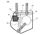
実施の形態3.
図11は、本発明の実施の形態3に係るウイルス不活化装置を冷暖房機能を有する空調機に設置した例を示す概略縦断面図である。実施の形態3における空調機20には、風上側より、プレフィルター24、熱交換器22、ファン21、およびプラズマ部23が配置されている。29は空調機本体を示す。また、図11では、空気の流れを矢印で示している。
FIG. 11: is a schematic longitudinal cross-sectional view which shows the example which installed the virus inactivation apparatus which concerns on
インフルエンザウイルス等のウイルスが流行するのは、秋ごろから春ごろにかけてであるため、空調機20は基本的に暖房運転となる。暖房運転時、熱交換器22は、温風を作成するために、Cu管、Alフィンが媒体により暖められ、40℃以上の高温状態となる。そして、その熱交換器22と外部からの冷たい空気が接触し、空気が温められ、ファン21の力で空調機外部(室内空間)へと送風されていく。
Since viruses such as influenza viruses are prevalent from autumn to spring, the
本実施の形態3における空調機20においては、熱交換器22の風下側にプラズマ部23(前述の高圧電極3、接地電極4、および可変型高圧電源5より構成される。)が装着されている。そのため、空調機20に入り込んだ空気は、熱交換器22で暖められ、その後、プラズマ部23を通ることとなる。
In the
このような構成によれば、空調機の従来の装置(プレフィルター、熱交換器、ファン)に、プラズマ部23を設置するだけで、高効率的なウイルス不活化効果を有する加熱部、プラズマ部をウイルスが通過する空調機が設計され、その結果、空調機により、ウイルスを効率的に不活化することができる。
According to such a configuration, a heating unit and a plasma unit having a highly efficient virus inactivation effect can be obtained simply by installing the
また、空調機には、プレフィルター24が装着されているが、このフィルター24は、空調機に吸引される空気中の粗塵を取り除く役割を果たしているため、効率的なウイルス不活化効果が得られることはいうまでもない。
The air conditioner is equipped with a pre-filter 24. The
また、本実施の形態3では、実施の形態1の構造に則ったウイルス不活化機能を有する空調機について、説明したが、前述したイオン付着部等を追加し、実施の形態2の構造に則ったウイルス不活化機能を有する空調機では、本実施の形態3よりも、更に高効率なウイルス不活化効果を有する空調機となることはいうまでもない。 In the third embodiment, the air conditioner having a virus inactivating function according to the structure of the first embodiment has been described. However, the ion adhering portion and the like described above are added, and the air conditioner conforms to the structure of the second embodiment. It goes without saying that an air conditioner having a virus inactivating function is an air conditioner having a more efficient virus inactivating effect than that of the third embodiment.
次に、空調機の動作について説明する。
図12は、空調機が実行するウイルス不活化方法の流れを示すフローチャートである。
装置の特徴は、空調機20が稼動し、室内に温風を送風するときのみ、プラズマ部23に高電圧を印加する点である。すなわち、空調機20の運転とウイルス不活化を連動することにより、省エネルギーなウイルス不活化運転を行うことが可能となっている。
Next, the operation of the air conditioner will be described.
FIG. 12 is a flowchart showing the flow of the virus inactivation method executed by the air conditioner.
The apparatus is characterized in that a high voltage is applied to the
空調機20が運転を開始すると、まずファン21が稼動する(S21)。そして、それと同時に室外機が稼動し、熱交換器22の加熱が始まる。空調機20に設置されている温度センサーにより、空調機20から送風される空気の温度を計測する。計測された温度は、温度判定部によって予め設定されている設定温度(室内温度)と比較される(S22)。そして、問題がなければ次の工程に移る。
測定された温度が設定温度値よりも低ければ、熱交換器22部が十分に加熱されていないことを意味するため、そのまま待機する。このようにして、浮遊しているウイルスを常時効率よく加熱していることを確認する。
When the
If the measured temperature is lower than the set temperature value, it means that 22 parts of the heat exchanger is not sufficiently heated, so that it stands by. In this way, it is confirmed that the floating virus is always heated efficiently.
次に、プラズマ部によるウイルス不活化工程が開始される(S23)。すなわち、高圧電極に可変型高電圧電源から高電圧が印加される(S24)。これにより、高圧電極と接地電極の間で放電が起こり、放電電流が接地電極に流れる。ここで、接地電極に流れる電流は、図示省略の制御基板等に設けられている電流判定部で計測される。計測された電流値は、電流判定部によって予め設定されている設定電流値と比較される。そして、問題がなければそのまま不活化処理工程が開始される。 Next, the virus inactivation process by the plasma part is started (S23). That is, a high voltage is applied to the high voltage electrode from the variable high voltage power supply (S24). Thereby, discharge occurs between the high-voltage electrode and the ground electrode, and a discharge current flows to the ground electrode. Here, the current flowing through the ground electrode is measured by a current determination unit provided on a control board (not shown). The measured current value is compared with a set current value set in advance by the current determination unit. If there is no problem, the inactivation process is started as it is.
測定された電流値が設定電流値よりも低ければ、高圧電極に印加される電圧が高くされ、測定された電流値が設定電流値よりも高ければ、高圧電極に印加される電圧が低くされる。このようにして、ウイルスを常時効率よく不活化処理されていることを確認する(S25)。
室内の温度が設定温度となったところで、空調機20は待機状態となる。これを感知し、高圧電極への高電圧印加をストップする。こうすることにより、ファン21が稼動し、空調機20から送風されているときにのみ、ウイルス不活化を実行することとなるため、無駄なエネルギーを消費することがない。
If the measured current value is lower than the set current value, the voltage applied to the high voltage electrode is increased, and if the measured current value is higher than the set current value, the voltage applied to the high voltage electrode is decreased. In this way, it is confirmed that the virus is always inactivated efficiently (S25).
When the room temperature reaches the set temperature, the
放電によるウイルス不活化工程が開始すると、タイマーが作動し、これら一連の工程における処理時間(工程の運転時間)が計測される(S26)。
これら一連の工程における処理時間(工程の運転時間)が設定時間に達すると、高圧電極3への高電圧印加が停止され、不活化工程は終了する(S27)。
その後、再び空調機20が稼動し、送風されるようになると、熱交換器22での加熱工程が開始され、上記の運転が繰り返されることになる。
When the virus inactivation process by discharge starts, a timer is activated, and the processing time (operation time of the process) in these series of processes is measured (S26).
When the processing time (process operation time) in the series of steps reaches the set time, the high voltage application to the
Thereafter, when the
なお、本実施の形態3においては、熱交換器22の下に、プラズマ部23を設置し、風上側よりプレフィルター24、熱交換器22、ファン21、およびプラズマ部23が配置されている構造となっているが、図13に示すように、熱交換器22の前部または上部に、プラズマ部25を配置し、このプラズマ部25の後に熱交換器22での加熱工程を行う空調機20aにしてもよい。その場合、図13に矢印30で示すように、プラズマ部25に吸引ファン(図示省略)を設けることにより、熱交換器22の加熱部を通過したウイルスに対し、プラズマをする構造とし、ベストモードでウイルスを不活化することができる。また、熱交換器22の前部または上部にプラズマ部25が配置されるため、冷房運転した際の結露水が付着することのない設計にすることができる。
In the third embodiment, the
1 送風機、2 加熱装置、3 高圧電極、4 接地電極、5 可変型高電圧電源、6 中和部電極、7 中和部電極、8 中和部電圧電源、9 風路、10 風路筐体、11 イオン付着部電極、12 イオン付着部電極、13 イオン付着部電圧電源、20 空調機、20a 空調機、21 ファン、22 熱交換器、23 プラズマ部、24 プレフィルター、25 プラズマ部(ファン付き)、29 空調機本体、100 装置、100a 装置、100b 装置。
DESCRIPTION OF
Claims (8)
空気と共に浮遊ウイルスを風路に取り込む送風機と、
浮遊ウイルスが通過する風路に配置され、
浮遊ウイルスを加熱処理する加熱装置と、
浮遊ウイルスをプラズマ処理する高圧電極、およびこの高圧電極に対向して設置された接地電極と、
正極と負極とで構成された第2電極と、
前記高圧電極に高電圧を印加するために接続された高圧電源と、
を備え、
前記加熱装置による空気加熱温度を30℃以上とするとともに、
前記風路の風上側から順に、前記加熱装置と、前記高圧電極と、前記接地電極と、前記第2電極と、を配置したことを特徴とするウイルス不活化装置。 A device that inactivates without trapping viruses floating in the air,
A blower that takes airborne viruses with the air into the airway;
Placed in the air passage through which airborne viruses pass,
A heating device for heating the floating virus,
A high-voltage electrode for plasma treatment of airborne viruses, and a ground electrode installed opposite to the high-voltage electrode;
A second electrode composed of a positive electrode and a negative electrode;
A high voltage power supply connected to apply a high voltage to the high voltage electrode;
With
While the air heating temperature by the said heating apparatus shall be 30 degreeC or more,
A virus inactivating apparatus comprising: the heating device, the high-voltage electrode, the ground electrode, and the second electrode arranged in order from the windward side of the air passage.
空気と共に浮遊ウイルスを風路に取り込む送風機と、
浮遊ウイルスが通過する風路に配置され、
浮遊ウイルスを加熱処理する加熱装置と、
浮遊ウイルスをプラズマ処理する高圧電極、およびこの高圧電極に対向して設置された接地電極と、
正極と負極とで構成された第2電極と、
前記高圧電極に高電圧を印加するために接続された高圧電源と、
を備え、
前記加熱装置による空気加熱温度を30℃以上とするとともに、
前記風路を形成する風路筐体と、
前記風路筐体の内部に、風上側から順に、前記加熱装置と、前記高圧電極と、前記接地電極と、空気の流れに対して平行に、かつ正極と負極が交互に配置された前記第2電極と、を配置したことを特徴とするウイルス不活化装置。 A device that inactivates without trapping viruses floating in the air,
A blower that takes airborne viruses with the air into the airway;
Placed in the air passage through which airborne viruses pass,
A heating device for heating the floating virus,
A high-voltage electrode for plasma treatment of airborne viruses, and a ground electrode installed opposite to the high-voltage electrode;
A second electrode composed of a positive electrode and a negative electrode;
A high voltage power supply connected to apply a high voltage to the high voltage electrode;
With
While the air heating temperature by the said heating apparatus shall be 30 degreeC or more,
An air passage housing forming the air passage;
Inside the air duct housing, from the windward side in order, and the heating device, and the high voltage electrode, said ground electrode, parallel to the air flow, and the positive and negative electrodes are alternately disposed first A virus inactivation apparatus characterized by comprising two electrodes.
空気と共に浮遊ウイルスを風路に取り込む送風機と、A blower that takes airborne viruses with the air into the airway;
浮遊ウイルスが通過する風路に配置され、Placed in the air passage through which airborne viruses pass,
浮遊ウイルスを加熱処理する加熱装置と、A heating device for heat-treating the floating virus;
浮遊ウイルスをプラズマ処理する高圧電極、およびこの高圧電極に対向して設置された接地電極と、A high-voltage electrode for plasma treatment of airborne viruses, and a ground electrode installed opposite to the high-voltage electrode;
前記プラズマ処理により荷電された浮遊ウイルス電気的に中和する中和部電極と、A neutralizing electrode for electrically neutralizing floating viruses charged by the plasma treatment;
前記高圧電極に高電圧を印加するために接続された高圧電源と、A high voltage power supply connected to apply a high voltage to the high voltage electrode;
を備え、With
前記加熱装置による空気加熱温度を30℃以上とするとともに、While the air heating temperature by the said heating apparatus shall be 30 degreeC or more,
前記風路の風上側から順に、前記加熱装置と、前記高圧電極と、前記接地電極と、前記中和部電極と、を配置したことを特徴とするウイルス不活化装置。A virus inactivating apparatus comprising: the heating device, the high-voltage electrode, the ground electrode, and the neutralizing portion electrode arranged in order from the windward side of the air passage.
空気と共に浮遊ウイルスを風路に取り込む工程と、
前記風路に取り込んだ前記空気と前記浮遊ウイルスに対し、30℃以上に加熱処理を行う工程と、
プラズマ処理を行う工程と、
を順に有し、
前記プラズマ処理の後に、荷電した浮遊ウイルスを電気的に中和させる工程を含むことを特徴とするウイルス不活化方法。 A method of inactivating without trapping viruses floating in the air,
Taking airborne virus with air into the airway;
A step of heat-treating the air and the airborne virus taken into the air passage to 30 ° C. or higher;
Performing a plasma treatment;
Have a in order,
A virus inactivation method characterized by comprising a step of electrically neutralizing a charged floating virus after the plasma treatment .
空気と共に浮遊ウイルスを風路に取り込む工程と、
前記風路に取り込んだ前記空気と前記浮遊ウイルスに対し、30℃以上に加熱処理を行う工程と、
プラズマ処理を行う工程と、
を順に有し、
前記プラズマ処理の後に、浮遊ウイルスを不活化させる少なくとも銀、銅、亜鉛のうちのいずれか1つの金属イオンを浮遊ウイルスに付着させる工程を含むことを特徴とするウイルス不活化方法。 A method of inactivating without trapping viruses floating in the air,
Taking airborne virus with air into the airway;
A step of heat-treating the air and the airborne virus taken into the air passage to 30 ° C. or higher;
Performing a plasma treatment;
Have a in order,
A virus inactivation method comprising a step of attaching at least one metal ion of silver, copper, or zinc to inactivate a suspended virus after the plasma treatment .
Priority Applications (1)
| Application Number | Priority Date | Filing Date | Title |
|---|---|---|---|
| JP2010278495A JP5683247B2 (en) | 2010-12-14 | 2010-12-14 | Virus inactivation apparatus, method thereof and air conditioner using the same |
Applications Claiming Priority (1)
| Application Number | Priority Date | Filing Date | Title |
|---|---|---|---|
| JP2010278495A JP5683247B2 (en) | 2010-12-14 | 2010-12-14 | Virus inactivation apparatus, method thereof and air conditioner using the same |
Publications (2)
| Publication Number | Publication Date |
|---|---|
| JP2012125360A JP2012125360A (en) | 2012-07-05 |
| JP5683247B2 true JP5683247B2 (en) | 2015-03-11 |
Family
ID=46643126
Family Applications (1)
| Application Number | Title | Priority Date | Filing Date |
|---|---|---|---|
| JP2010278495A Active JP5683247B2 (en) | 2010-12-14 | 2010-12-14 | Virus inactivation apparatus, method thereof and air conditioner using the same |
Country Status (1)
| Country | Link |
|---|---|
| JP (1) | JP5683247B2 (en) |
Families Citing this family (1)
| Publication number | Priority date | Publication date | Assignee | Title |
|---|---|---|---|---|
| JP7196550B2 (en) * | 2018-11-14 | 2022-12-27 | 三菱電機株式会社 | air purifier |
Family Cites Families (5)
| Publication number | Priority date | Publication date | Assignee | Title |
|---|---|---|---|---|
| JPS647964A (en) * | 1987-06-30 | 1989-01-11 | Toshiba Corp | Air cleaner and air conditioner equipped with this cleaner |
| JP3509741B2 (en) * | 1999-12-27 | 2004-03-22 | 株式会社セキュリティーシステム | Non-discharge air purifier, non-discharge air cleaning method, and non-discharge air sterilizer |
| JP4796281B2 (en) * | 2004-02-06 | 2011-10-19 | 財団法人工業技術研究院 | Hot-air plasma generator, hot-air plasma hand-drying sterilization device, closed-type hot-air plasma drying sterilization device, and circulating hot-air plasma sterilization device |
| JP2007260244A (en) * | 2006-03-29 | 2007-10-11 | Adhoc Kobe:Kk | Sterilizer |
| JP2011242091A (en) * | 2010-05-20 | 2011-12-01 | Osaka Gas Co Ltd | Hot air supply device |
-
2010
- 2010-12-14 JP JP2010278495A patent/JP5683247B2/en active Active
Also Published As
| Publication number | Publication date |
|---|---|
| JP2012125360A (en) | 2012-07-05 |
Similar Documents
| Publication | Publication Date | Title |
|---|---|---|
| JP5855122B2 (en) | Microbe / virus capture / inactivation apparatus and method thereof | |
| JP5546630B2 (en) | Microbe / virus capture / inactivation equipment | |
| KR101925848B1 (en) | Fine dust remover using negative and positive ionized charge | |
| JP2003035445A (en) | Air cleaner | |
| CN103331209B (en) | A kind of method and apparatus utilizing corona discharge to remove microbial aerosol in room air | |
| JP5774119B2 (en) | Methods for capturing and inactivating microorganisms and viruses | |
| CN111256248A (en) | High-efficient air disinfection purification treatment device | |
| JP2002058731A (en) | Air cleaner and air conditioner with ion generator | |
| KR101925846B1 (en) | Fine dust remover using string electric field | |
| JP5683247B2 (en) | Virus inactivation apparatus, method thereof and air conditioner using the same | |
| JP3680120B2 (en) | Ion generator, air purifier and air conditioner equipped with the same | |
| JP2010142773A (en) | Dust collector | |
| KR100535705B1 (en) | Humidification apparatus having plasma discharger with three dimensional cell structure and method thereof | |
| JP2013043114A (en) | Virus and microorganism removal device | |
| KR101569629B1 (en) | Apparatus for purifying air | |
| CN113843046A (en) | Dust collecting polar plate and air purifying device | |
| JP5800717B2 (en) | Mist-like substance removal device | |
| JP2012115798A (en) | Air cleaning device | |
| JP2018110648A (en) | Air purifier and fan filter unit | |
| JP2007196199A (en) | Discharge device, air cleaning apparatus and air-flow generating device equipped with the discharge device | |
| CN214332984U (en) | Sterilizing machine | |
| KR101600742B1 (en) | Anti-microbial apparatus using charged anti-microbial material | |
| CN211781643U (en) | High-efficient air disinfection purification treatment device | |
| CN216879839U (en) | Dust collecting polar plate and air purifying device | |
| CN212618790U (en) | Air purification module, air conditioner and air sterilizing machine |
Legal Events
| Date | Code | Title | Description |
|---|---|---|---|
| A621 | Written request for application examination |
Free format text: JAPANESE INTERMEDIATE CODE: A621 Effective date: 20121011 |
|
| A977 | Report on retrieval |
Free format text: JAPANESE INTERMEDIATE CODE: A971007 Effective date: 20130315 |
|
| A131 | Notification of reasons for refusal |
Free format text: JAPANESE INTERMEDIATE CODE: A131 Effective date: 20130409 |
|
| A131 | Notification of reasons for refusal |
Free format text: JAPANESE INTERMEDIATE CODE: A131 Effective date: 20140325 |
|
| A521 | Written amendment |
Free format text: JAPANESE INTERMEDIATE CODE: A523 Effective date: 20140418 |
|
| TRDD | Decision of grant or rejection written | ||
| A01 | Written decision to grant a patent or to grant a registration (utility model) |
Free format text: JAPANESE INTERMEDIATE CODE: A01 Effective date: 20141216 |
|
| A61 | First payment of annual fees (during grant procedure) |
Free format text: JAPANESE INTERMEDIATE CODE: A61 Effective date: 20150113 |
|
| R150 | Certificate of patent or registration of utility model |
Ref document number: 5683247 Country of ref document: JP Free format text: JAPANESE INTERMEDIATE CODE: R150 |
|
| R250 | Receipt of annual fees |
Free format text: JAPANESE INTERMEDIATE CODE: R250 |
|
| R250 | Receipt of annual fees |
Free format text: JAPANESE INTERMEDIATE CODE: R250 |
|
| R250 | Receipt of annual fees |
Free format text: JAPANESE INTERMEDIATE CODE: R250 |
|
| R250 | Receipt of annual fees |
Free format text: JAPANESE INTERMEDIATE CODE: R250 |
|
| R250 | Receipt of annual fees |
Free format text: JAPANESE INTERMEDIATE CODE: R250 |
|
| R250 | Receipt of annual fees |
Free format text: JAPANESE INTERMEDIATE CODE: R250 |