JP5683184B2 - Desk system - Google Patents
Desk system Download PDFInfo
- Publication number
- JP5683184B2 JP5683184B2 JP2010208455A JP2010208455A JP5683184B2 JP 5683184 B2 JP5683184 B2 JP 5683184B2 JP 2010208455 A JP2010208455 A JP 2010208455A JP 2010208455 A JP2010208455 A JP 2010208455A JP 5683184 B2 JP5683184 B2 JP 5683184B2
- Authority
- JP
- Japan
- Prior art keywords
- wiring
- housing portion
- electronic device
- exhaust heat
- top plate
- Prior art date
- Legal status (The legal status is an assumption and is not a legal conclusion. Google has not performed a legal analysis and makes no representation as to the accuracy of the status listed.)
- Expired - Fee Related
Links
Images


Landscapes
- Cooling Or The Like Of Electrical Apparatus (AREA)
Description
本発明は、オフィスやトレーダールームなどの執務空間にて使用され、内部に電子機器を収容可能なデスクシステムに関する。 The present invention relates to a desk system that can be used in an office space such as an office or a trader room, and can accommodate electronic devices therein.
従来より、オフィスやトレーダールームなどの執務空間では、天板下などの内部に電子機器を収容可能なデスクシステムが使用されている。このようなデスクシステムには、例えば特許文献1および2に開示されているように、収容された電子機器から生じた熱を外部へ排出する排熱ファンを備えているものがある。
Conventionally, in office spaces such as offices and trader rooms, desk systems that can accommodate electronic devices under the top board have been used. Such a desk system includes, for example, a heat exhaust fan that exhausts heat generated from a stored electronic device to the outside as disclosed in
しかしながら、内部に排熱ファンを備えているデスクシステムでは、排熱ファンの取付・取り外し作業やメンテナンス作業などをデスクシステムの内部で行うため、作業スペースが狭く作業を行いにくいという問題がある。特に近年、搭載する電子機器の性能向上もあって排熱ファンによる冷却性能の向上が求められて排熱ファンが大型化しており、取付・取り外し作業やメンテナンス作業を行いにくい。 However, in a desk system having a heat exhaust fan inside, there is a problem that the work space is narrow and difficult to perform because the work of attaching / removing the heat exhaust fan and the maintenance work are performed inside the desk system. Particularly in recent years, the performance of electronic devices to be mounted has been improved, and the cooling performance of the exhaust heat fan has been demanded, and the exhaust heat fan has become larger, making it difficult to perform installation / removal work and maintenance work.
本発明は、上述する問題点に鑑みてなされたもので、デスクシステムの内部に収容された電子機器から生じた熱を効率よく外部に排出できるとともに、排熱ファンの取付・取り外し作業やメンテナンス作業を容易に行うことができるデスクシステムを提供することを目的とする。 The present invention has been made in view of the above-described problems, and can efficiently exhaust heat generated from an electronic device housed in a desk system to the outside, and can also be used for attaching / detaching a heat exhaust fan and performing maintenance work. An object of the present invention is to provide a desk system that can easily perform the above.
上記目的を達成するため、本発明に係るデスクシステムは、天板と、床面上に立設し前記天板を支持する支持部と、を備え、前記床面と前記天板との間の内部空間には、該内部空間の下部側に位置し電子機器が収容される電子機器収容部と、該電子機器収容部の上部に隣接するとともに該電子機器収容部と連通し、該電子機器収容部の空気を前記内部空間の外方へ排出する排熱ファンが収容される排熱ファン収容部と、該排熱ファン収容部の前側に隣接し、前記天板に形成された開口部を介して前記天板の上方の空間と連通可能に設けられ、配線が収容される配線収容部と、が形成され、前記排熱ファン収容部は、前記開口部および前記配線収容部を通して前記天板の上方の空間と連通可能であり、前記排熱ファンは、前記天板の上方の空間から前記配線収容部を介して着脱可能であることを特徴とする。 In order to achieve the above object, a desk system according to the present invention includes a top plate and a support unit that stands on the floor surface and supports the top plate, and is provided between the floor surface and the top plate. The internal space is located on the lower side of the internal space and accommodates an electronic device housing, and is adjacent to the upper portion of the electronic device housing and communicates with the electronic device housing. Through the opening formed in the top plate, adjacent to the front side of the exhaust heat fan accommodating portion, and the exhaust heat fan accommodating portion for accommodating the exhaust heat fan for exhausting the air of the outside to the outside of the internal space And a wiring accommodating portion that is provided so as to be able to communicate with a space above the top plate and accommodates wiring, and the exhaust heat fan accommodating portion is formed through the opening and the wiring accommodating portion. the space above and communicable der is, the exhaust heat fan, the space above the ceiling plate Characterized in that it is detachable through al the wire housings.
本発明では、電子機器収容部の空気を内部空間の外方へ排出する排熱ファンを備えていることにより、電子機器から生じた熱によって高温となった空気を効率よく内部空間の外方へ排出することができる。
ここで、天板には配線収容部の上方に開口部が形成されていて、排熱ファン収容部が開口部および配線収容部を通して天板の上方の空間と連通可能である。このため、使用者は、天板の上方の空間から開口部および配線収容部を通して排熱ファンにアクセスすることができる。すなわち、使用者は、天板の上方から、開口部及び配線収容部を通して排熱ファンの取付・取り外し作業やメンテナンス作業を行うことができるため、天板下部の狭いスペースで排熱ファンの取付・取り外し作業やメンテナンス作業を行う従来のデスクシステムと比べて、排熱ファンの取付・取り外し作業やメンテナンス作業を容易に行うことができる。
In the present invention, by providing the exhaust heat fan that exhausts the air in the electronic device housing part to the outside of the internal space, the air that has become hot due to the heat generated from the electronic device is efficiently discharged to the outside of the internal space. Can be discharged.
Here, an opening is formed in the top plate above the wiring housing portion, and the exhaust heat fan housing portion can communicate with the space above the top plate through the opening and the wiring housing portion. For this reason, the user can access the exhaust heat fan from the space above the top plate through the opening and the wiring accommodating portion. In other words, since the user can perform installation / removal work and maintenance work of the exhaust heat fan from above the top plate through the opening and the wiring housing portion, the installation / removal of the exhaust heat fan can be performed in a narrow space below the top plate. Compared to a conventional desk system that performs removal work and maintenance work, it is possible to easily perform the work of installing / removing the heat exhaust fan and maintenance work.
また、本発明に係るデスクシステムでは、前記配線収容部は、前記電子機器収容部の上部に隣接するとともに、該電子機器収容部および前記排熱ファン収容部と通気可能であることが好ましい。
このように、配線収容部は、電子機器収容部の上部に隣接するとともに、電子機器収容部および排熱ファン収容部と通気可能であることにより、電子機器から生じた熱によって高温となった空気の一部は、配線収容部を介して排熱ファン収容部へ移動することができる。そして、電子機器から生じた熱によって高温となった空気が排熱ファンへ移動するための移動経路を広く確保することができるため、内部空間の排熱効果を高めることができる。
In the desk system according to the present invention, it is preferable that the wiring housing portion is adjacent to an upper portion of the electronic device housing portion and is ventable to the electronic device housing portion and the exhaust heat fan housing portion.
As described above, the wiring housing portion is adjacent to the upper portion of the electronic device housing portion, and is capable of ventilating with the electronic device housing portion and the exhaust heat fan housing portion, so that the air heated to high temperature by the heat generated from the electronic device. A part of can move to the exhaust heat fan accommodating part via the wiring accommodating part. And since the movement path | route for the air which became high temperature with the heat which generate | occur | produced from the electronic device moves to an exhaust heat fan can be ensured widely, the exhaust heat effect of internal space can be heightened.
また、本発明に係るデスクシステムでは、前記電子機器収容部と前記配線収容部との間、および前記排熱ファン収容部と前記配線収容部との間には、着脱可能であるとともに互いを区画する区画板が設けられていて、前記区画板には通気孔が形成されていることが好ましい。
このように、電子機器収容部と配線収容部との間、および排熱ファン収容部と配線収容部との間には、着脱可能であるとともに互いを区画する区画板が設けられていて、区画板には通気孔が形成されていることにより、高温となった空気を排熱ファンへ案内しつつ使用者が配線収容部で作業しているときに排熱ファンや電子機器に接触することを確実に防ぐことができる。
In the desk system according to the present invention, the electronic device housing portion and the wiring housing portion and the exhaust heat fan housing portion and the wiring housing portion are detachable and partition each other. It is preferable that a partition plate is provided, and a vent hole is formed in the partition plate.
Thus, between the electronic device accommodating portion and the wiring accommodating portion, and between the exhaust heat fan accommodating portion and the wiring accommodating portion, a partition plate that is detachable and partitions each other is provided. The board has ventilation holes that allow the user to contact the exhaust heat fan and electronic equipment when working in the wiring housing while guiding the hot air to the exhaust heat fan. It can be surely prevented.
また、本発明に係るデスクシステムでは、前記天板には、前記開口部を閉塞可能な閉塞部材が設けられていることが好ましい。
このように、天板には、開口部を閉塞可能な閉塞部材が設けられていることにより、開口部を閉塞すれば、開口部から配線収容部に空気が流入することを防止できる。このため、排熱ファンは、開口部から配線収容部に流入した空気を吸引することがなく、電子機器収容部の空気を外部へ確実に排出することができるため、排熱効果を高めることができる。
In the desk system according to the present invention, it is preferable that the top plate is provided with a closing member capable of closing the opening.
As described above, the top plate is provided with the closing member capable of closing the opening, so that if the opening is closed, air can be prevented from flowing into the wiring housing portion from the opening. For this reason, the exhaust heat fan can reliably exhaust the air in the electronic device housing portion to the outside without sucking the air that has flowed into the wiring housing portion from the opening, thereby enhancing the heat exhaust effect. it can.
また、本発明に係るデスクシステムでは、前記閉塞部材の縁部および前記開口部の縁部の少なくとも一方には、他方と当接する弾性部材が設けられ、前記弾性部材を弾性変形させることで前記配線収容部と前記天板の上方の空間との間で配線可能であることが好ましい。
このように、閉塞部材の縁部および開口部の縁部の少なくとも一方には、他方と当接する弾性部材が設けられていることにより、開口部を確実に閉塞することができる。また、開口部を挿通するケーブルなどが設置されている場合に、ケーブルの側面に弾性部材が弾性変形して密着することによって、ケーブルが挿通されたことによってできる開口部と閉塞部材との隙間を少なくすることができる。
In the desk system according to the present invention, at least one of the edge of the closing member and the edge of the opening is provided with an elastic member that contacts the other, and the wiring is formed by elastically deforming the elastic member. It is preferable that wiring is possible between the accommodating portion and the space above the top plate.
Thus, at least one of the edge of the closing member and the edge of the opening is provided with the elastic member that contacts the other, so that the opening can be reliably closed. In addition, when a cable or the like that passes through the opening is installed, the elastic member is elastically deformed and brought into close contact with the side surface of the cable, so that a gap between the opening and the closing member that is formed by the insertion of the cable is eliminated. Can be reduced.
本発明によれば、デスクシステムの内部に収容された電子機器から生じた熱を効率よく外部に排出できるとともに、排熱ファンの取付・取り外し作業やメンテナンス作業を容易に行うことができる。 ADVANTAGE OF THE INVENTION According to this invention, while being able to discharge | emit efficiently the heat which generate | occur | produced from the electronic device accommodated in the inside of a desk system, the attachment / detachment operation | work and maintenance operation | work of a heat exhaust fan can be performed easily.
以下、本発明の実施形態によるデスクシステムについて、図1乃至図7に基づいて説明する。
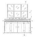
図1および図2に示すように、本実施形態によるデスクシステム1は、平面視矩形状の天板部(天板)2と、床面F上に立設し天板部2の両側端部を支持する1対の支持部3,3と、を備えている。
図1に示すように、天板部2と床面Fとの間には内部空間Sが形成されている。そして、この内部空間Sは、電子機器11が収容される電子機器収容部S1と、電子機器収容部S1の空気を内部空間Sの外方に排出する排熱ファン12が収容される排熱ファン収容部S2と、電子機器11と接続される配線13や天板部2上にて使用される機器に接続される配線13などが収容される配線収容部S3と、から構成されている。この配線13とは、電子機器11と電源や各種機器、照明装置と電源などを接続するために用いられるものであり、電源用や通信用の各種ケーブルのみならず、OAタップ、ローゼットなども含む。
Hereinafter, a desk system according to an embodiment of the present invention will be described with reference to FIGS.
As shown in FIG. 1 and FIG. 2, the
As shown in FIG. 1, an internal space S is formed between the
また、デスクシステム1は、天板部2において、使用者が位置する前部と反対側の後部で上側に突出するように立設する支柱4を備えており、この支柱4にはディスプレイ14が取り付けられている。
そして、図1において、ディスプレイ14は、表示画面が、使用者(不図示)が図中の左側となる前側から図中右側となる後側を見ることで確認できるように支柱4に取り付けられている。
In addition, the
In FIG. 1, the
図1および図3に示すように、天板部2は、電子機器11およびディスプレイ14と接続されたキーボード15(図1参照)などが載置される天板本体21と、天板本体21よりも後側に位置し支柱4が固定される支柱固定部22とを備えている。天板本体21および支柱固定部22は、ともに支持部3,3に支持されている。
天板本体21と支柱固定部22とは、同じ高さに前後方向へ互いに間隔をあけるように設置されている。この天板本体21と支柱固定部22との間には、配線用開口部(開口部)23が形成されている。
As shown in FIGS. 1 and 3, the
The top plate
配線用開口部23は、配線収容部S3の上部に位置している。そして、この配線用開口部23を介して配線収容部S3と天板部2の上方の空間とが連通可能で、使用者が天板部2の上方の空間から配線収容部S3へアクセス可能となるように構成されている。また、配線用開口部23は、天板部2の上方の空間から配線収容部S3へ配線13が挿入可能であるとともに、使用者が天板部2の上方の空間から手を挿入して配線収容部S3で作業ができる大きさに形成されている。配線用開口部23は、天板部2の略全幅にわたって形成されている。
また、天板部2は、配線用開口部23を閉塞可能なカバー部材(閉塞部材)24を備えている。なお、カバー部材24は、1つ部材で配線用開口部23を閉塞する形態としてもよく、複数の部材で配線用開口部23を閉塞する形態としてもよい。
The wiring opening 23 is located above the wiring housing portion S3. The wiring housing portion S3 and the space above the
In addition, the
カバー部材24には、その前端部および後端部にゴムなどの弾性部材25が取り付けられている。カバー部材24が配線用開口部23に設置されると、弾性部材25が配線用開口部23の縁部と接触し、配線用開口部23を略密閉することができる。
また、図3に示すように、配線用開口部23に配線(ケーブル)13が挿通された状態でカバー部材24を設置すると、弾性部材25が配線13の側面に沿った形状に弾性変形し、配線13とカバー部材24との隙間を少なくすることができる。
更に、使用者がカバー部材24を配線開口部23へ取り付けたり、配線開口部23から取り外したりする際に、弾性部材25を弾性変形させることでカバー部材24を持ち易くすることができる。
本実施形態では、弾性部材25は、中空の管状に形成されている。なお、弾性部材25は、帯状など他の形状に形成されていてもよい。また、弾性部材25は、カバー部材24の前端部および後端部だけでなく側端部に取り付けられていてもよい。
An
As shown in FIG. 3, when the
Furthermore, when the user attaches or removes the
In the present embodiment, the
図1および図3に示すように、支柱固定部22は、横方向に延在するとともに前後方向に所定の間隔をあけて設置された一対の角型パイプ26,26を備えている。
一対の角型パイプ26,26は、横方向複数箇所に設けられた固定手段30によって一体とされている。固定手段30は、一対の角型パイプ26,26の上下にそれぞれ設置された板部材27,28(図1参照)と、一対の角型パイプ26,26間に挿通されて2つの板部材27,28同士を連結する固定具29とを有する。そして、一対の角型パイプ26、26は、固定具29によって連結された板部材27、28により上下側から挟持されることで一体となるように固定されている。なお、隣り合う固定手段30は、所定の間隔をあけて一対の角型パイプ26,26に取り付けられており、一対の角型パイプ26,26間は、固定手段30が取り付けられている部分以外は、上下方向に貫通している。
また、固定手段30の上側の板部材27には支柱4が固定されており、板部材27は支柱4の支持手段としても機能している。
なお、一対の角型パイプ26,26に対して、固定手段30を取り付ける位置や、固定手段30の数は適宜設定されてもよい。
As shown in FIGS. 1 and 3, the
The pair of
Further, the
In addition, the position where the fixing means 30 is attached to the pair of
図4に示すように、天板部2と床面Fとの間の内部空間Sにおいて、後側には後面パネル31が、両側方には側面パネル32,32が、それぞれ配設されている。また、内部空間Sの前側には開口部33が形成されるとともに開口部33を開放・閉塞する扉34が設置されている。
なお、天板部2を複数配列して使用する場合は、配列された複数の天板部2の両側方に側面パネル32,32が配設されていてもよい。
内部空間Sは、扉34で開口部33を閉塞することで、外部と区画された状態となっている。
As shown in FIG. 4, in the internal space S between the
When a plurality of the
The internal space S is separated from the outside by closing the
本実施形態では、扉34は2枚の中折れ戸35,35からなる中折れ観音式扉となっている。具体的には、中折れ戸35の一方の端部35aが水平面内において回転可能に取り付けられて、他方の端部35bが開口部33に設けられたレール36に沿って水平方向に移動することで、開口部33を開放・閉鎖している。
そして、扉34を開放したときに、2枚の中折れ戸35,35の他方の端部35bをレール36から外すことによって、開口部33を更に拡張することができる。
In the present embodiment, the
When the
図1に示すように、電子機器収容部S1は、内部空間Sにおいて下部側に位置している。また、排熱ファン収容部S2および配線収容部S3は、内部空間Sにおいて上部側に位置している。そして、排熱ファン収容部S2および配線収容部S3は前後方向に隣接しており、後側に排熱ファン収容部S2、前側に配線収容部S3となるように配されている。
電子機器収容部S1は、開口部33に面していて、開口部33からのアクセスが可能となっている。また、排熱ファン収容部S2および配線収容部S3は、天板部2と面していて、配線収容部S3については上記のとおり天板部2に設けられた配線用開口部23からアクセスすることが可能となっている。
電子機器収容部S1、排熱ファン収容部S2および配線収容部S3は、それぞれ内部空間Sの全幅にわたって形成されている。
As shown in FIG. 1, the electronic device housing portion S <b> 1 is located on the lower side in the internal space S. Further, the exhaust heat fan accommodating portion S2 and the wiring accommodating portion S3 are located on the upper side in the internal space S. And the exhaust heat fan accommodating part S2 and the wiring accommodating part S3 are adjacent to the front-back direction, and are arrange | positioned so that it may become the exhaust heat fan accommodating part S2 in the rear side, and the wiring accommodating part S3 in the front side.
The electronic device housing portion S1 faces the
The electronic device housing part S1, the exhaust heat fan housing part S2, and the wiring housing part S3 are each formed over the entire width of the internal space S.
電子機器収容部S1には、収容される電子機器11を載置するとともに床面F上を走行するキャスター37を備えた棚板38が設置されている。そして、扉34を開いて開口部33を開放した状態で棚板38を移動させることで、電子機器11を電子機器収容部S1に出し入れすることができる。
In the electronic device housing portion S1, a
図1および図5に示すように、電子機器収容部S1と配線収容部S3との間には、両者を区画するための第1区画板(区画板)41および第2区画板(区画板)42が横方向に複数配列されている。第1区画板41および第2区画板42は、前後方向に隣接しており、後側に第1区画板41、前側に第2区画板42が設置されている。第1区画板41および第2区画板42には、複数のスリット(通気孔)43(図5参照)が形成されている。
そして、第1区画板41および第2区画板42に複数のスリット43が形成されていることにより、電子機器収容部S1および配線収容部S3間における空気の流出入が可能となっている。
As shown in FIG. 1 and FIG. 5, a first partition plate (partition plate) 41 and a second partition plate (partition plate) for partitioning both between the electronic device housing portion S1 and the wiring housing portion S3. A plurality of 42 are arranged in the horizontal direction. The
Since the
電子機器収容部S1と配線収容部S3との間には、前後方向に延在する長尺の支持材44が横方向に互いに間隔をあけて複数設置されている。第1区画板41および第2区画板42は、複数の支持材44の上に設置されていて、支持材44に対して着脱可能に構成されている。第1区画板41および第2区画板42の上において、配線収容部S3となる範囲には配線13(図1参照)が載置されている。
Between the electronic device housing part S1 and the wiring housing part S3, a plurality of
図5に示すように、第1区画板41は、面方向を水平面とする水平板部41aと、水平板部41aの後端部に接続されて面方向を鉛直方向とする鉛直板部41bと、水平板部41aの前端部に接続されて上方に立ち上がる立ち上がり部41cとを備えている。
鉛直板部41bは、排熱ファン収容部S2と配線収容部S3との間に位置し、その上端部は天板部2の下面近傍まで達している。
また、立ち上がり部41cは、鉛直板部41bよりも低く、配線収容部S3の空間を分割しない高さに形成されている。
スリット43は、水平板部41aおよび鉛直板部41bに形成されている。そして、鉛直板部41bにスリット43が形成されていることにより、電子機器収容部S1および排熱ファン収容部S2間における空気の流出入が可能となっている。
また、第1区画板41には、水平板部41aの横方向の端部に、配線13(図1参照)が挿通される切欠き部41dが形成されている。
As shown in FIG. 5, the
The
The rising
The
Further, the
第2区画板42は、側面視略C字型状に形成され、面方向を水平方向とする水平板部42aと、水平板部42aの前端部および後端部に接続されている立ち上がり部42bとを備えている。スリット43は、水平板部41aに形成されている。
立ち上がり部42bは第1区画板41の立ち上がり部41cと同様に、配線収容部S3の空間を分割しない高さに形成されている。
また、第2区画板42には、水平板部42aの横方向の端部に、配線13(図1参照)が挿通される切欠き部42dが形成されている。
The
Like the rising
Further, the
図1および図5に示すように、排熱ファン収容部S2は、支持材44の上側に位置している。そして、排熱ファン12は、支持材44に固定具46で固定されている。なお、本実施形態では、排熱ファン12は、防振ゴム47(図5参照)を介して支持材44に固定されている。
また、本実施形態では、排熱ファン12に横方向に延設されたクロスファンが使用されており、下方および側方の空気を吸引するとともに、この空気を上方へ排出している。
排熱ファン12の下方には電子機器収容部S1が位置し、側方には配線収容部S3が位置しているため、排熱ファン12は電子機器収容部S1および配線収容部S3の空気を吸引している。
そして、排熱ファン12は、吸引した空気を上方に排出し、この排熱ファン12から排出された空気は、支柱固定部22の一対の角型パイプ26,26の間から天板部2の上方へ排出されている。ここで、この支柱固定部22の一対の角型パイプ26,26の間を排熱用開口部48とする。排熱用開口部48は排熱ファン12の上部に位置している。
As shown in FIGS. 1 and 5, the exhaust heat fan housing portion S <b> 2 is located above the
Further, in the present embodiment, a cross fan extending in the lateral direction is used as the
Since the electronic device housing portion S1 is located below the
The
図1に示すデスクシステム1において、電子機器11を使用することによって電子機器11から熱が生じると、この熱によって電子機器収容部S1の電子機器11周辺の空気が高温となる。電子機器収容部S1の高温となった空気は上昇し、排熱ファン収容部S2および配線収容部S3へ移動する。このとき、電子機器収容部S1から配線収容部S3へ上昇する空気は、図5に示す第1区画板41の水平板部41aおよび第2区画板42の水平板部42aに形成されたスリット43を通過している。
また、排熱ファン12が駆動していることにより、電子機器収容部S1および配線収容部S3の空気が排熱ファン12に吸引される。このとき、配線収容部S3から排熱ファン12に吸引される空気は、図5に示す第1区画板41の鉛直板部41bに形成されたスリット43を通過している。
そして、排熱ファン12に吸引された空気は、上方に向かって強制的に送風され、排熱用開口部48から天板部2の上方の空間へ排出される。
なお、図5に示すように、扉34には、通気用のスリット34aが形成されているため、電子機器収容部S1には外部から空気が流入している。
In the
Further, since the
The air sucked into the
As shown in FIG. 5, the
図6および図7に示すように、配線収容部S3は、第1区画板41を取り外すと、前後方向に隣接する排熱ファン収容部S2と連通した状態となっている。そして、この状態において、使用者が天板部2の上方の空間から配線用開口部23および配線収容部S3を通して排熱ファン12に接触できるようになっている。
また、配線収容部S3および配線用開口部23は、排熱ファン12を出し入れ可能な大きさに形成されていて、排熱ファン12の取付・取り外し作業やメンテナンス作業を天板部2の上方の空間から行うことができるようになっている。
As shown in FIGS. 6 and 7, when the
Further, the wiring housing portion S3 and the
なお、排熱ファン12の取付・取り外し作業やメンテナンス作業を行うときは、図6に示すように、まず、カバー部材24(図6参照)を外して、配線用開口部23を開放させる。続いて、第1区画板41および第2区画板42を取り外して排熱ファン収容部S2と配線収容部S3とを連通させる。そして、天板部2の上方の空間から、配線用開口部23および配線収容部S3を介して排熱ファン12の取付・取り外し作業やメンテナンス作業を行う。
When performing the attaching / detaching operation or the maintenance operation of the
具体的には、排熱ファン12をデスクシステム1から取り外すときには、まず第1区画板41を取り外す。次に、排熱ファン12と支持材44との固定を解除し、支持材44上で排熱ファン12を配線収容部S3へスライドさせる。そして、排熱ファン12を持ち上げて配線用開口部23から天板部2の上方へと取り出すことで、排熱ファン12がデスクシステム1から取り外される。
排熱ファン12を取り付けるときは、同様にまず第1区画板41を取り外す。次に、排熱ファン12を配線用開口部23から配線収容部S3へ挿入し、支持材44に沿って排熱ファン収容部S2へスライドさせて支持材44へ固定する。
このように、配線収容部S3を排熱ファン12の取付・取り外し作業やメンテナンス作業を行うスペースとして使用することができる。
なお、上記においては取付・取り外し作業に際して第1区画板41を取り外すものとしたが、これに限るものではない。第1区画板41において鉛直板部41bのみを取り外すことが可能な場合には、当該鉛直板部41bのみを取り外せば良く、少なくとも配線収容部S3と排熱ファン収容部S2とが連通する状態となれば良い。
Specifically, when removing the
When the
In this way, the wiring housing portion S3 can be used as a space for performing the attaching / detaching operation and the maintenance operation of the
In the above description, the
次に、上述したデスクシステム1の効果について説明する。
本実施形態によるデスクシステム1によれば、上記のとおり天板部2の上方の空間から配線収容部S3を介して排熱ファン12に使用者が接触することができ、配線収容部S3を作業スペースとして使用することができるため、排熱ファン12の取付・取り外し作業やメンテナンス作業を容易に行うことができて、作業効率を向上させることができる。特に、排熱ファン12がクロスファンのような形状が大きい場合において、作業スペースを確保することが出来るため、作業効率を向上させることができる。
Next, the effect of the
According to the
また、電子機器11から生じた熱によって高温となった空気の一部は配線収容部S3を介して排熱ファン12に吸引されることにより、高温となった空気が排熱ファン収容部S2へ移動するための移動経路を広く確保することができるため、内部空間Sの排熱効果を高めることができる。
Further, a part of the air heated to high temperature by the heat generated from the
また、天板部2は配線用開口部23を閉塞可能なカバー部材24を備えているとともに、カバー部材24には、その前端部および後端部にゴムなどの弾性部材25が取り付けられているため、カバー部材24によって配線用開口部23が閉塞されているときは、弾性部材25が配線用開口部23の縁部と接触して配線用開口部23とカバー部材24との隙間を少なくすることができる。
これにより、配線用開口部23とカバー部材24との隙間から配線収容部S3へ空気が流入することが少ないため、外部の空気が直接排熱ファン12に吸引されることがなく、電子機器11から生じた熱によって高温となった空気を効率よく外部へ排出することができる。
The
As a result, air hardly flows into the wiring housing portion S3 from the gap between the
また、配線用開口部23に配線(ケーブル)13が挿通されているときに、弾性部材25が配線13の形状に沿って弾性変形するため、配線13が挿通されていても、カバー部材24と配線用開口部23の縁部との隙間を少なくすることができる。
また、配線収容部S3と電子機器収容部S1との間に、第1区画板41および第2区画板42が設けられて、第1区画板41の鉛直板部41bが、配線収容部S3と排熱ファン収容部S2とを区画しているため、配線収容部S3で作業する使用者が排熱ファン12および電子機器11に接触する懼れがなく、安全性を高めることができる。また、配線収容部S3に配設された配線13などが電子機器11や排熱ファン12と接触することを防止することができる。
In addition, when the wiring (cable) 13 is inserted through the
Further, a
以上、本発明によるデスクシステム1の実施形態について説明したが、本発明は上記の実施形態に限定されるものではなく、その趣旨を逸脱しない範囲で適宜変更可能である。
例えば、上述した実施形態では、天板部2から上方に突出する支柱4が設けられて、この支柱4にディスプレイ14が取り付けられているが、ディスプレイ14に代わって、照明器具や収納棚などが取り付けられていてもよい。また、支柱4を設けない形態としてもよい。
また、上述した実施形態では、電子機器収容部S1と配線収容部S3とは第1区画板41および第2区画板42に形成されたスリット43によって空気の出入が可能であるが、電子機器収容部S1と配線収容部S3との空気の出入を遮断して、電子機器11から生じる熱が配線収容部S3を介さずに排熱ファン収容部S2へ流入する形態としてもよい。
As mentioned above, although embodiment of the
For example, in the above-described embodiment, the
Moreover, in embodiment mentioned above, although electronic device accommodating part S1 and wiring accommodating part S3 can enter / exit air with the
また、上述した実施形態では、カバー部材24の前端部および後端部に弾性部材25が取り付けられているが、カバー部材24に弾性部材25を設けずに、配線用開口部23の縁部に弾性部材25を取り付けてもよい。また、カバー部材24の前端部および後端部、配線用開口部23の縁部の両方に弾性部材25を取り付けてもよく、これら両方に弾性部材25を取り付けていなくてもよい。
また、上述した実施形態では、配線収容部S3は、電子機器収容部S1の上部に隣接していて、電子機器収容部S1と通気可能であるが、電子機器収容部S1と離間していてもよく、また、電子機器収容部S1と通気可能でなくてもよい。
In the embodiment described above, the
In the above-described embodiment, the wiring housing portion S3 is adjacent to the upper portion of the electronic device housing portion S1 and can be ventilated with the electronic device housing portion S1, but may be separated from the electronic device housing portion S1. Moreover, it may not be able to ventilate with the electronic device housing part S1.
また、上述した実施形態では、一対の支持部3,3で天板部2を支持しているが、天板部2を支持する支持部3の数は2つ以外でもよい、
また、上述した実施形態では、天板部2と床面Fとの間の内部空間Sには、後側に後面パネル31が設置されているが、2台のデスクシステム1をその後面が互いに対向するように設置する場合は、後面パネル31を設置しなくてもよい。
Moreover, in embodiment mentioned above, although the top-
In the above-described embodiment, the
1 デスクシステム
2 天板部(天板)
3 支持部
11 電子機器
12 排熱ファン
13 配線
23 配線用開口部(開口部)
24 カバー部材(閉塞部材)
25 弾性部材
41 第1区画板(区画板)
42 第2区画板(区画板)
43 スリット(通気孔)
S1 電子機器収容部
S2 排熱ファン収容部
S3 配線収容部
F 床面
1
DESCRIPTION OF
24 Cover member (blocking member)
25
42 Second partition plate (partition plate)
43 Slit (vent hole)
S1 Electronic device housing portion S2 Waste heat fan housing portion S3 Wiring housing portion
F Floor
Claims (5)
床面上に立設し前記天板を支持する支持部と、を備え、
前記床面と前記天板との間の内部空間には、
該内部空間の下部側に位置し電子機器が収容される電子機器収容部と、
該電子機器収容部の上部に隣接するとともに該電子機器収容部と連通し、該電子機器収容部の空気を前記内部空間の外方へ排出する排熱ファンが収容される排熱ファン収容部と、
該排熱ファン収容部の前側に隣接し、前記天板に形成された開口部を介して前記天板の上方の空間と連通可能に設けられ、配線が収容される配線収容部と、が形成され、
前記排熱ファン収容部は、前記開口部および前記配線収容部を通して前記天板の上方の空間と連通可能であり、
前記排熱ファンは、前記天板の上方の空間から前記配線収容部を介して着脱可能であることを特徴とするデスクシステム。 With the top plate,
A support unit that stands on the floor and supports the top plate,
In the internal space between the floor and the top plate,
An electronic device housing part that is located on the lower side of the internal space and houses an electronic device;
An exhaust heat fan housing portion that is adjacent to an upper portion of the electronic device housing portion, communicates with the electronic device housing portion, and houses a heat exhaust fan that exhausts air in the electronic device housing portion to the outside of the internal space; ,
Formed is a wiring housing portion that is adjacent to the front side of the exhaust heat fan housing portion and is provided so as to be able to communicate with a space above the top plate through an opening formed in the top plate and accommodates wiring. And
The exhaust heat fan housing section, Ri upper space communicable with Der of the top plate through the opening and the wire housings,
The desk system characterized in that the heat exhaust fan is detachable from the space above the top plate via the wiring housing portion .
前記区画板には通気孔が形成されていることを特徴とする請求項2に記載のデスクシステム。 Between the electronic device housing portion and the wiring housing portion, and between the exhaust heat fan housing portion and the wiring housing portion, partition plates that are detachable and partition each other are provided,
The desk system according to claim 2, wherein a vent hole is formed in the partition plate.
At least one of the edge of the closing member and the edge of the opening is provided with an elastic member that contacts the other, and the elastic member is elastically deformed to elastically deform the space above the wiring housing portion and the top plate. The desk system according to claim 4, wherein wiring is possible between the desk system and the desk system.
Priority Applications (1)
| Application Number | Priority Date | Filing Date | Title |
|---|---|---|---|
| JP2010208455A JP5683184B2 (en) | 2010-09-16 | 2010-09-16 | Desk system |
Applications Claiming Priority (1)
| Application Number | Priority Date | Filing Date | Title |
|---|---|---|---|
| JP2010208455A JP5683184B2 (en) | 2010-09-16 | 2010-09-16 | Desk system |
Publications (2)
| Publication Number | Publication Date |
|---|---|
| JP2012061172A JP2012061172A (en) | 2012-03-29 |
| JP5683184B2 true JP5683184B2 (en) | 2015-03-11 |
Family
ID=46057534
Family Applications (1)
| Application Number | Title | Priority Date | Filing Date |
|---|---|---|---|
| JP2010208455A Expired - Fee Related JP5683184B2 (en) | 2010-09-16 | 2010-09-16 | Desk system |
Country Status (1)
| Country | Link |
|---|---|
| JP (1) | JP5683184B2 (en) |
Cited By (1)
| Publication number | Priority date | Publication date | Assignee | Title |
|---|---|---|---|---|
| CN108783901A (en) * | 2018-06-01 | 2018-11-13 | 苏州市东成办公科技有限公司 | A kind of computer desk with heat sinking function |
Families Citing this family (3)
| Publication number | Priority date | Publication date | Assignee | Title |
|---|---|---|---|---|
| JP6040001B2 (en) * | 2012-11-05 | 2016-12-07 | 株式会社岡村製作所 | Workstation equipment |
| KR101526176B1 (en) * | 2015-02-12 | 2015-06-05 | 팬톰 주식회사 | Console Desk |
| CN105919285A (en) * | 2016-06-02 | 2016-09-07 | 华北理工大学 | Multimedia teaching desk |
Family Cites Families (3)
| Publication number | Priority date | Publication date | Assignee | Title |
|---|---|---|---|---|
| JP2553835Y2 (en) * | 1992-02-05 | 1997-11-12 | 株式会社イトーキクレビオ | Panel mounting structure on desk |
| JPH063137U (en) * | 1992-06-29 | 1994-01-18 | 株式会社イトーキ | desk |
| JP2000041752A (en) * | 1998-07-31 | 2000-02-15 | Kokuyo Co Ltd | Desk |
-
2010
- 2010-09-16 JP JP2010208455A patent/JP5683184B2/en not_active Expired - Fee Related
Cited By (1)
| Publication number | Priority date | Publication date | Assignee | Title |
|---|---|---|---|---|
| CN108783901A (en) * | 2018-06-01 | 2018-11-13 | 苏州市东成办公科技有限公司 | A kind of computer desk with heat sinking function |
Also Published As
| Publication number | Publication date |
|---|---|
| JP2012061172A (en) | 2012-03-29 |
Similar Documents
| Publication | Publication Date | Title |
|---|---|---|
| US7600720B2 (en) | Horizontal cable manager | |
| JP5683184B2 (en) | Desk system | |
| JP2014240727A (en) | Outdoor unit | |
| JP5444513B2 (en) | control panel | |
| EP1453367B1 (en) | Control box | |
| EP3402318A1 (en) | 4-post rack with integrated intake/exhaust regions | |
| EP1491079B1 (en) | Assembly for installation of power electronics modules and installation method | |
| JP5130960B2 (en) | Rack for mounting electronic equipment and cooling mechanism thereof | |
| TW201346502A (en) | Heat dissipating system for computer | |
| JP2018189267A (en) | Outdoor unit for air conditioner | |
| JP5542598B2 (en) | Desk system | |
| JP2015005657A (en) | Equipment unit-housing cabinet | |
| JP2768602B2 (en) | control panel | |
| JP7248393B2 (en) | Communication equipment rack | |
| JP4212441B2 (en) | Electronic equipment rack | |
| JP2011089687A (en) | Air conditioning system for computer room | |
| JP2009218519A (en) | Cooling device of electronic apparatus | |
| JP2015090950A (en) | Cabinet for storing electrical and electronic apparatuses | |
| JP2015005656A (en) | Equipment unit-housing cabinet | |
| JP5201611B2 (en) | Electronic equipment cooling structure | |
| WO2021064986A1 (en) | Electronic apparatus | |
| JP2018189265A (en) | Outdoor unit for air conditioner | |
| JP2018189264A (en) | Outdoor unit for air conditioner | |
| NL2006026C2 (en) | Housing for electrical equipment. | |
| JP2006040918A (en) | Rack for electronic apparatus |
Legal Events
| Date | Code | Title | Description |
|---|---|---|---|
| A621 | Written request for application examination |
Free format text: JAPANESE INTERMEDIATE CODE: A621 Effective date: 20130912 |
|
| A977 | Report on retrieval |
Free format text: JAPANESE INTERMEDIATE CODE: A971007 Effective date: 20140311 |
|
| A131 | Notification of reasons for refusal |
Free format text: JAPANESE INTERMEDIATE CODE: A131 Effective date: 20140408 |
|
| A521 | Written amendment |
Free format text: JAPANESE INTERMEDIATE CODE: A523 Effective date: 20140606 |
|
| TRDD | Decision of grant or rejection written | ||
| A01 | Written decision to grant a patent or to grant a registration (utility model) |
Free format text: JAPANESE INTERMEDIATE CODE: A01 Effective date: 20141216 |
|
| A61 | First payment of annual fees (during grant procedure) |
Free format text: JAPANESE INTERMEDIATE CODE: A61 Effective date: 20150113 |
|
| R150 | Certificate of patent or registration of utility model |
Ref document number: 5683184 Country of ref document: JP Free format text: JAPANESE INTERMEDIATE CODE: R150 |
|
| R250 | Receipt of annual fees |
Free format text: JAPANESE INTERMEDIATE CODE: R250 |
|
| S533 | Written request for registration of change of name |
Free format text: JAPANESE INTERMEDIATE CODE: R313533 |
|
| R350 | Written notification of registration of transfer |
Free format text: JAPANESE INTERMEDIATE CODE: R350 |
|
| R250 | Receipt of annual fees |
Free format text: JAPANESE INTERMEDIATE CODE: R250 |
|
| LAPS | Cancellation because of no payment of annual fees |