JP5680864B2 - Water spray nozzle - Google Patents
Water spray nozzle Download PDFInfo
- Publication number
- JP5680864B2 JP5680864B2 JP2010036847A JP2010036847A JP5680864B2 JP 5680864 B2 JP5680864 B2 JP 5680864B2 JP 2010036847 A JP2010036847 A JP 2010036847A JP 2010036847 A JP2010036847 A JP 2010036847A JP 5680864 B2 JP5680864 B2 JP 5680864B2
- Authority
- JP
- Japan
- Prior art keywords
- nozzle
- sealing member
- water
- water discharge
- outlet
- Prior art date
- Legal status (The legal status is an assumption and is not a legal conclusion. Google has not performed a legal analysis and makes no representation as to the accuracy of the status listed.)
- Active
Links
Images


Description
この発明は、車輌が通過するトンネルの壁面等に設置される、消火設備の水噴霧ノズルに関するものであり、更に述べると、水噴霧ノズルの防塵構造に関するものである。 The present invention relates to a water spray nozzle for fire extinguishing equipment installed on a wall surface of a tunnel through which a vehicle passes, and more particularly to a dustproof structure for a water spray nozzle.
従来、例えば、トンネル用の消火設備として、遠投用ノズルと近投用ノズルととを備えた水噴霧ヘッドが用いられている(例えば、特許文献1、2参照)。
Conventionally, for example, as a fire extinguishing equipment for a tunnel, a water spray head including a long throw nozzle and a near throw nozzle is used (see, for example,
前記トンネル内では、塵埃が発生するが、この塵埃が水噴霧ノズルの放水口に堆積すると、放水障害が発生し、設計通りに放水区画に放水することができなくなる。そこで、前記塵埃の堆積を防止するため、水噴霧ノズルの放水口にキャップ状の防塵カバーを装着している。この防塵カバーは、放水点検時や実火災時に前記水噴霧ノズルに消火用水が圧送されると、その圧力により押されて外れる様になっている。 Dust is generated in the tunnel, but if this dust accumulates on the water outlet of the water spray nozzle, a water discharge failure occurs, and the water cannot be discharged into the water discharge section as designed. In order to prevent the accumulation of dust, a cap-shaped dustproof cover is attached to the water outlet of the water spray nozzle. This dustproof cover is pushed and removed by the pressure when water for fire extinguishing is pumped to the water spray nozzle at the time of water discharge check or actual fire.
従来の防塵カバーは、前述のように消火用水の圧力により自動的に水噴霧ノズルから外れるが、放水の停止により自動的に元の状態に戻るように構成されていない。そのため、放水停止後、作業員の手により前記防塵カバーを前記水噴霧ノズルに装着し元の状態に戻している。一般に、トンネル内には、多数の水噴霧ノズルが配設され、しかも、背の届かぬ高所に配設されているので、人手による防塵カバーの装着作業は、時間及び労力がかかるとともに、危険でもある。又、この点検作業は、法的義務はないものの、比較的頻繁に行われ、例えば、毎年2回行われており、前記防塵カバーの装着作業に時間がかかればかかるほどメンテナンス費用が嵩むことになる。 As described above, the conventional dustproof cover is automatically removed from the water spray nozzle by the pressure of fire-extinguishing water, but is not configured to automatically return to the original state when the water discharge is stopped. Therefore, after the water discharge is stopped, the dust cover is attached to the water spray nozzle by an operator's hand to return to the original state. In general, a large number of water spray nozzles are installed in tunnels, and they are installed at high places where they cannot be reached. Therefore, it is time consuming and labor intensive to install the dust cover manually. But there is. In addition, although there is no legal obligation, this inspection work is performed relatively frequently. For example, it is performed twice a year, and the longer it takes to install the dust cover, the higher the maintenance cost. Become.
この発明は、上記事情に鑑み、簡単に防塵カバーを元の状態に戻すことができるようにすることを目的にする。 In view of the above circumstances, an object of the present invention is to easily return the dust cover to the original state.
この発明は、先端内側にノズル放水口が形成されるノズル本体と、前記ノズル放水口の前面に設けられた変位可能な封止部材と、を備えた水噴霧ノズルであって、前記ノズル本体の胴部には、連通孔が設けられ、前記封止部材は、回動可能に軸支されて、ノズル放水口を閉鎖する封止部と、該封止部に連続しノズル本体に回動可能に軸止されているアーム部と、該アーム部の内面に設けられ、前記連通孔を封止する栓部材と、前記封止部材を軸支する軸部に設けられ、前記封止部材を前記ノズル放水口に圧接させる付勢手段と、を備え、放水時には、放水圧により前記封止部材が変位して前記ノズル放水口が開放され、放水停止時には、前記付勢手段の付勢力により前記封止部材が元の位置に戻り前記ノズル放水口を閉鎖することを特徴とする。 The present invention is a water spray nozzle comprising a nozzle body in which a nozzle water outlet is formed inside the tip, and a displaceable sealing member provided on the front surface of the nozzle water outlet . The body portion is provided with a communication hole, and the sealing member is pivotally supported so as to close the nozzle outlet, and can be rotated to the nozzle body continuously to the sealing portion. An arm portion that is pivotally fixed to the inner surface, a plug member that is provided on an inner surface of the arm portion and seals the communication hole, a shaft portion that pivotally supports the sealing member, and the sealing member is Urging means that press-contacts the nozzle outlet, and when the water is discharged, the sealing member is displaced by the water discharge pressure to open the nozzle water outlet, and when the water discharge is stopped, the sealing is performed by the urging force of the urging means. to the stop member, characterized that you close the nozzle outlets back to the original position .
この発明は、先端内側にノズル放水口が形成されるノズル本体と、前記ノズル放水口の前面に設けられた変位可能な封止部材と、を備えた水噴霧ノズルであって、前記封止部材は、回動可能に軸支されて、前記封止部材を軸支する軸部に設けられ、前記封止部材を前記ノズル放水口に圧接させる付勢手段と、ヘッド本体のノズル放水口と反対側に、放水圧によって摺動するピストンと、該ピストンを収容したシリンダ部を設け、該ピストンのピストンロッドと前記封止部材の連結部を連結部材により連結し、放水時には、放水圧により前記封止部材が変位して前記ノズル放水口が開放され、放水停止時には、前記付勢手段の付勢力により前記封止部材が元の位置に戻り前記ノズル放水口を閉鎖することを特徴とする。 The present invention is a water spray nozzle comprising a nozzle body in which a nozzle water outlet is formed inside a tip, and a displaceable sealing member provided in front of the nozzle water outlet, the sealing member Is pivotally supported and provided on a shaft portion that pivotally supports the sealing member, and biasing means that presses the sealing member against the nozzle water outlet, opposite to the nozzle water outlet of the head body. on the side, a piston sliding by releasing water pressure, provided the cylinder accommodating the piston, and connected by a connecting member connecting portions of the sealing member and the piston rod of the piston, at the time of water discharge, said the release pressure sealing The stop member is displaced to open the nozzle water outlet, and when the water discharge is stopped, the sealing member returns to its original position and closes the nozzle water outlet by the urging force of the urging means .
この発明は、先端内側にノズル放水口が形成されるノズル本体と、前記ノズル放水口の前面に設けられた変位可能な封止部材と、を備えた水噴霧ノズルであって、前記ノズル本体の胴部には、連通孔が設けられ、前記封止部材は、回動可能に軸支されて、ノズル放水口を閉鎖する封止部と、該封止部に連続しノズル本体に回動可能に軸止されているアーム部と、該アーム部の内面に設けられ、前記連通孔を封止する栓部材と、前記封止部材を軸支する軸部に設けられ、前記封止部材を前記ノズル放水口に圧接させる付勢手段と、を備え、放水時には、放水圧により前記封止部材が変位して前記ノズル放水口が開放され、放水停止時には、前記付勢手段の付勢力により前記封止部材が元の位置に戻り前記ノズル放水口を閉鎖するので、放水中にはノズル本体内を流れる消火用水の一部が 連通孔から放出され、栓部を押し上げる。そのため、前記封止部は、放水パターンの外側まで押圧され、放水されている間中、その開放状態を維持するので、この機構は、開度保持機構ということもできる。前記開放状態では、前記封止部材が放水パターンを制限することがないので、設計通りの放水パターンを得ることができる。また、放水が終了すると、ノズル放水口を確実に閉鎖することができる。 The present invention is a water spray nozzle comprising a nozzle body in which a nozzle water outlet is formed inside the tip, and a displaceable sealing member provided on the front surface of the nozzle water outlet . The body portion is provided with a communication hole, and the sealing member is pivotally supported so as to close the nozzle outlet, and can be rotated to the nozzle body continuously to the sealing portion. An arm portion that is pivotally fixed to the inner surface, a plug member that is provided on an inner surface of the arm portion and seals the communication hole, a shaft portion that pivotally supports the sealing member, and the sealing member is Urging means that press-contacts the nozzle outlet, and when the water is discharged, the sealing member is displaced by the water discharge pressure to open the nozzle water outlet, and when the water discharge is stopped, the sealing is performed by the urging force of the urging means. Runode to close the nozzle outlets are stop members return to the original position, during the water discharge Some of Fire water flowing in the nozzle body is released from the communicating hole, pushing up the plug portion. Therefore, since the sealing portion is pressed to the outside of the water discharge pattern and maintains its open state while water is discharged, this mechanism can also be called an opening degree holding mechanism. In the open state, since the sealing member does not limit the water discharge pattern, a water discharge pattern as designed can be obtained. Moreover, when the water discharge is completed, the nozzle water outlet can be reliably closed.
この発明は、先端内側にノズル放水口が形成されるノズル本体と、前記ノズル放水口の前面に設けられた変位可能な封止部材と、を備えた水噴霧ノズルであって、前記封止部材は、回動可能に軸支されて、前記封止部材を軸支する軸部に設けられ、前記封止部材を前記ノズル放水口に圧接させる付勢手段と、ヘッド本体のノズル放水口と反対側に、放水圧によって摺動するピストンと、該ピストンを収容したシリンダ部を設け、該ピストンのピストンロッドと前記封止部材の連結部を連結部材により連結し、放水時には、放水圧により前記封止部材が変位して前記ノズル放水口が開放され、放水停止時には、前記付勢手段の付勢力により前記封止部材が元の位置に戻り前記ノズル放水口を閉鎖するので、放水開始時にはヘッド本体内を流れる消火用水の一部がピストンを押圧し、前記封止部材が連結部材により引っ張られる。そのため、前記封止部材は、放水パターンの外側まで押圧され、放水されている間中、その開放状態を維持するので、この機構は、開度保持機構ということもできる。前記開放状態では、前記封止部材が放水パターンを制限することがないので、設計通りの放水パターンを得ることができる。また、放水が終了すると、ノズル放水口を確実に閉鎖することができる。 The present invention is a water spray nozzle comprising a nozzle body in which a nozzle water outlet is formed inside a tip, and a displaceable sealing member provided in front of the nozzle water outlet, the sealing member Is pivotally supported and provided on a shaft portion that pivotally supports the sealing member, and biasing means that presses the sealing member against the nozzle water outlet, opposite to the nozzle water outlet of the head body. on the side, a piston sliding by releasing water pressure, provided the cylinder accommodating the piston, and connected by a connecting member connecting portions of the sealing member and the piston rod of the piston, at the time of water discharge, said the release pressure sealing When the water discharge is stopped, the sealing member returns to its original position and closes the nozzle water discharge port when the water discharge is stopped. Flowing in Some of the fire water presses the piston, the sealing member is pulled by the connecting member. Therefore, since the sealing member is pressed to the outside of the water discharge pattern and maintains its open state while water is discharged, this mechanism can also be called an opening degree holding mechanism. In the open state, since the sealing member does not limit the water discharge pattern, a water discharge pattern as designed can be obtained. Moreover, when the water discharge is completed, the nozzle water outlet can be reliably closed.
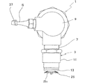
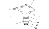
この発明の第1実施形態を図1〜図5により説明する。車輌の通過するトンネルの壁面(図示省略)には、消火設備の放水ヘッド1が配設されている。この放水ヘッド1は、垂直方向に配設される近投水噴霧ノズル(以下、「近投用ノズル」という)3と、水平方向に配設される遠投水噴霧ノズル(以下、「遠投用ノズル」という)5と、を備えている。
A first embodiment of the present invention will be described with reference to FIGS. On the wall surface (not shown) of the tunnel through which the vehicle passes, a
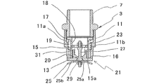
この近投用ノズル3は、ヘッド連結筒7を介してヘッド本体9に連通されている。前記近投用ノズル3は、筒状の外筒11と、該外筒11内に挿着され、先端15a外側に環状鍔部13を有する内筒15と、を備え、前記内筒15と外筒11との間には、円環状の第1のノズル放水口16が形成されている。
The
前記内筒15の後端部にはガイドフランジ部17が設けられ、該ガイドフランジ部17は、外筒11の第1段部11aの内周面に摺動可能に当接している。前記第1段部11aは第2段部11bと連続しており、この第2段部11bと前記ガイドフランジ部17との間には、コイルばね等の付勢部材19が張設され、前記両者11b、17は、離れる方向に付勢されている。そのため、内筒15の環状鍔部13は外筒11に圧接されるので、前記第1のノズル放水口16は閉鎖される。前記内筒15のガイドフランジ部17側には、前記第1のノズル放水口16に連通する複数の連通孔18が所定の間隔で設けられている。
A
前記内筒15の先端15a側には、第2のノズル放水口20を有するノズル取付部材21が螺着され、該ノズル取付部材21の先端には、前記環状鍔部13が設けられている。前記内筒15内には、支持環23と封止部材25とを連結する連結ロッド27が同心状に配設されている。前記支持環23は、その内側に複数の通水用開口が円環状に設けられている。前記支持環23は封止部材25を第2のノズル放水口の前面側に保持する。
A
前記封止部材25は、消火用水を分散させるデフレクタの形状に形成され、平板部25aと折曲部25bとを備え、前記折曲部25bには、複数の切欠部25cが設けられている。前記連結ロッド27の封止部材25側には、膨出部29が設けられているが、この膨出部29は、例えば、コーンの形状に形成され、火災監視時には、第1のノズル放水口20内に収まっているが、放水時には、該ノズル放水口20から飛び出しコーンの役割をする。つまり、水の流れを斜め方向に変える。
The sealing
前記ノズル取付部材21と前記支持環23との間には、コイルばね等の付勢部材31が張設され、前記両者21,23は互いに離れる方向に付勢されている。そのため、前記封止部材25は第2のノズル放水口20に圧接されるので、前記ノズル放水口20は閉鎖される。
An urging
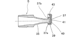
前記遠投用ノズル5は、前記近投用ノズル3と直交方向に設けられている。この遠投用ノズル5は、ヘッド本体9に螺着されるノズル本体35と、該ノズル本体35に装着されるアタッチメント部材37と、を備えている。前記ノズル本体35の先端外側には、矩形状の鍔部39が設けられ、該鍔部39の内側には矩形状のノズル放水口40が設けられている。
The
前記アタッチメント部材37は、前記鍔部39の上部を挟持する第1のアタッチメント37bと、前記鍔部39の下部を挟持する第2のアタッチメント37aと、を備えているが、この第1及び第2アタッチメント部材37a、37bは、前記ノズル放水口40を包囲するように前記鍔部39に装着された後、ボルト等により締め付けられて一体となる。前記アタッチメント部材37には、回動可能に軸支された封止部材41と、該封止部材41をノズル放水口40側に付勢するコイルばね等の付勢部材43と、を備えている。
The
次に、本実施形態の作動について説明する。
「通常時(火災監視時)」
図2に示すように、放水ヘッド1の近投用ノズル3の第1のノズル放水口16は、環状鍔部13の圧接により閉鎖され、第2のノズル放水口20は、封止部材25の圧接により閉鎖され、又、図4に示すように、遠投用ノズル5のノズル放水口40は、封止部材41の圧接により閉鎖されている。そのため、前記ノズル放水口16,20,40内に塵埃が堆積する恐れはない。
Next, the operation of this embodiment will be described.
"Normal time (when monitoring fire)"
As shown in FIG. 2, the first nozzle
「点検作業時又は実火災時」
図示しないポンプが起動し消火用水が放水ヘッド1に圧送されると、該消火用水は近投用ノズル3と遠投用ノズル5に流れ込む。
"During inspection work or actual fire"
When a pump (not shown) is activated and fire extinguishing water is pumped to the
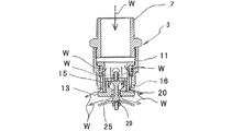
前記近投用ノズル3に流れ込んだ消火用水Wは、内筒15内を直進し第2のノズル放水口20へ向かうと共に、その一部は、連通孔18を通って第1のノズル放水口16に向かうので、前記消火用水Wは、ノズル取付部材21、膨出部29及び封止部材25を押圧するとともに、環状鍔部13を押圧する。そのため、付勢部材19、31により付勢されていた環状鍔部13及び封止部材25は、水圧を受けて移動するので、前記ノズル放水口16、20が開放され、消火用水Wが放出される。
The fire-extinguishing water W that has flowed into the
前記近投用ノズル3の第1のノズル放水口16から放出される消火用水Wは、環状鍔部13に衝突して流れ方向を変えられながら放出され、又、第2のノズル放水口20から放出される消火用水Wは、コーンの働きをして水の流れの向きを斜め方向に変える、膨出部29に衝突した後、封止部材25に案内されながら放出される。この時、前記封止部材25は、デフレクタとして機能できる形状に形成されているので、所望の放水パターンを得ることができる。
The fire-extinguishing water W discharged from the
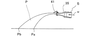
又、前記遠投用ノズル5に流れ込んだ消火用水Wは、ノズル本体35内を直進しノズル放水口40へ向かうので、前記消火用水Wは封止部材41を押圧する。そのため、付勢部材43により付勢されていた封止部材41は、水圧を受けて回動するので、前記ノズル放水口40が開放され、消火用水Wが放出される。前記遠投用ノズルの第2のノズル放水口40から放出された消火用水Wは、例えば、図5に示す放水パターンPで放水されるが、この遠投用ノズル5では、前記封止部材41がノズル放水口40の上側で軸支されているために、消火用水の一部(上側)が、開放した前記封止部材41の下端部に衝突しその放出方向が規制される。そのため、前記放水パターンPの最短着地距離(遠投用ノズル5から最も近い点迄の長さ)Paは、封止部材41をつけない場合と同一であるが、最長着地距離(遠投用ノズル5から最も離れた点迄の長さ)Pbは、封止部材41をつけない場合よりも短くなる。
Further, the fire-extinguishing water W that has flowed into the long-
「点検作業終了後又は復旧作業時」
前記ポンプを停止させ、放水ヘッド1への給水を停止すると、放水が終了するとともに、付勢部材19、31のばね力により内筒15及び封止部材25が摺動して元の状態に戻る(図2参照)。そのため、前記環状鍔部13及び封止部材25は、前記ノズル放水口16、20に圧接されるので、前記ノズル放水口16.20は、確実に閉鎖される。
又、遠投用ノズル5においては、放水が終了すると、付勢部材43のばね力により封止部材41が回動して元の状態に戻る(図4参照)。そのため、封止部材41は、ノズル放水口40に圧接されるので、ノズル放水口40は、確実に閉鎖される。
"After inspection work or during recovery work"
When the pump is stopped and the water supply to the
In the
この発明の第2実施形態を図6により説明するが、図1〜図5と同一図面符号は、その名称も機能も同一である。この実施形態と第1実施形態との相違点は、封止部材41をノズル放水口40の上側で軸支する代わりに、その下側で軸支し、上側から下側に向かって回転するようにしたことである。
A second embodiment of the present invention will be described with reference to FIG. 6. The same reference numerals as those in FIGS. 1 to 5 have the same names and functions. The difference between this embodiment and the first embodiment is that instead of pivotally supporting the sealing
この実施形態では、前記遠投用ノズル5の第2のノズル放水口40から放出された消火用水Wは、例えば、図6に示す放水パターンP1で放水される。この放水パターンP1では、封止部材41がノズル放水口40の下側で軸支されているために、消火用水の一部(下側)が、開放した前記封止部材41の上端部に衝突しその放出方向が規制される。そのため、前記放水パターンP1の最短着地距離Paは、第1実施形態のそれより短くなり、又、最長着地距離Pbは、第1実施形態のそれより長くなり、封止部材41を設けていない場合と同一となる。
In this embodiment, the fire-extinguishing water W discharged from the second
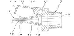
この発明の第3実施形態を図7〜図8により説明するが、図1〜図6と同一図面符号は、その名称も機能も同一である。この実施形態と第1の実施形態との主なる相違点は、次の通りである。
(1)遠投用ノズル5の封止部材41が、封止部41aとアーム部41bとからなる略L字状部材であり、前記封止部41aでノズル放水口40を閉鎖すること。なお、前記アーム部41bの後端部は、ノズル本体35の後端部に回動可能に軸止されている。
A third embodiment of the present invention will be described with reference to FIGS. 7 to 8. The same reference numerals as those in FIGS. 1 to 6 have the same names and functions. The main differences between this embodiment and the first embodiment are as follows.
(1) The sealing
(2)前記アーム部41bの内面に栓部44が突設され、ノズル本体35の外周面とアーム部41bの内面は、離間していること。
(3)前記ノズル本体35の胴部に、前記栓部44により閉鎖される連通孔42が設けられていること。この連通孔42の中心軸は、ノズル本体35の軸芯に対し、斜め上方に傾斜しているが、その傾斜角度は必要に応じて適宜選択される。
(2) The
(3) A communication hole 42 that is closed by the
(4)ばねなどの付勢部材43は、ノズル放水口40及び連通孔42の閉方向に封止部材41を付勢していること。
(4) The biasing
この実施形態では、消火用水Wがノズル本体35に供給されると、封止部41aを押圧するとともに、その一部は連通孔42を通り栓部44に衝突する。そのため、封止部材41の封止部41aは、ノズル放水口40から離れ、放水が開始されるとともに、連通孔42を通る消火用水により前記アーム部41bは押し上げられるので、封止部41aの先端部は、ノズル放水口40の上方の位置で維持される。前記封止部41aの位置は、放水の間中、維持され、ノズル放水口40の開放状態を維持するので、この機構は、いわば、開度保持機構ということもできる。前記開放状態では、前記封止部材41が放水パターンを制限することがない様に保持開度が設定されているので、設計通りの放水パターンを得ることができる。
In this embodiment, when fire-extinguishing water W is supplied to the
ノズル本体35に対する消火用水Wの供給を停止すると、付勢部材43の付勢力により、封止部41aはノズル放水口40を圧接閉鎖し、栓部44は連通孔42を圧接閉鎖する。なお、本実施の形態では、封止部材41のアーム部41bをノズル本体35の上側に配設したが、その下側に設け、連通孔を下側に設けても良いことは勿論である。
When the supply of the fire-extinguishing water W to the
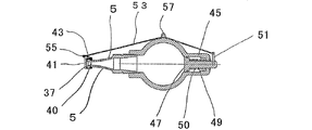
この発明の第4実施形態を図9〜図11により説明するが、図1〜図8と同一図面符号は、その名称も機能も同一である。この実施形態と前記第1実施形態との相違は、封止部材41を消火用水Wの水圧で開放させる代わりに、ピストンで開放させるようにしたことである。
A fourth embodiment of the present invention will be described with reference to FIGS. 9 to 11. The same reference numerals as those in FIGS. 1 to 8 have the same names and functions. The difference between this embodiment and the first embodiment is that the sealing
即ち、放水ヘッド1内の遠投用ノズル5と反対側に、シリンダ部45を設け、該シリンダ部45にピストン47を嵌着するとともに、該ピストン47に前記シリンダ部45を貫通するピストンロッド49を連結する。前記シリンダ部45内のピストンロッド49の外周には、前記ピストン47を遠投用ノズル5側に付勢するコイルばね等の付勢部材50が設けられている。
That is, a
該ピストンロッド49の後端部、即ち、シリンダ部45から露出している部分、に支持棒51を立設し、該支持棒51の先端部に、ワイヤやロープなどの連結部材53の一端を連結し、その他端を前記封止部材41の連結部55に連結する。この連結部材53の長さは、放水時に封止部材41が放水パターンに接触しない位置、例えば、ノズル放水口40の斜め上方、まで引っ張れる長さに調整されている。前記連結部材53は、ヘッド本体9の頂部に設けた案内突部57内を挿通されることによりその移動を規制される。
A
本実施形態の遠投用ノズル5の作動について説明する。
「通常時(火災監視時)」
図9、10に示すように、遠投用ノズル5のノズル放水口40は、封止部材41の圧接により封鎖されている。そのため、前記ノズル放水口40内に塵埃が堆積する恐れはない。
The operation of the
"Normal time (when monitoring fire)"
As shown in FIGS. 9 and 10, the
「点検作業時又は実火災時」
図示しないポンプが起動し消火用水Wが放水ヘッド1に圧送されると、該消火用水Wは遠投用ノズル5に流れ込む。そうすると、ヘッド本体9内のピストン47は、前記消火用水Wにより押圧されて摺動するので、ピストンロッド49が遠投用ノズル5と反対方向に摺動する。そのため、前記封止部材41は、放水圧で押圧されると同時に連結部材53により引っ張られるため、矢印A41方向に回転するので、ノズル放水口40が開放され、放水が開始される(図11参照)。
"During inspection work or actual fire"
When a pump (not shown) is activated and the fire-extinguishing water W is pumped to the
この時、前記封止部材41は、例えば、130度以上回転し、ノズル放水口40の斜め上方に位置するが、この封止部材41は、放水されている間中、その開放状態を維持するので、この機構は、開度保持機構ということもできる。前記開放状態では、前記封止部材41が放水パターンを制限することがない。そのため、前記封止部材41が設けられていない状態と同一状態で放水されるので、設計通りの放水パターンを得ることができる。
At this time, the sealing
「点検作業終了後又は復旧作業時」
前記ポンプを停止させ、放水ヘッド1への給水を停止すると、放水が終了するとともに、ピストン47は付勢部材50の付勢力によりシリンダ部45内を摺動して元の状態に戻る(図10参照)。そのため、前記封止部材41は、前記ノズル放水口40に圧接されるので、前記ノズル放水口40は、確実に閉鎖される。
"After inspection work or during recovery work"
When the pump is stopped and the water supply to the
この発明の実施形態は、上記に限定されるものではなく、例えば、第4実施形態における封止部材を、放水ヘッドの上側で支持する代わりに、その下側で支持するようにしても良い。この場合には、案内突部は、放水ヘッドの下側に設けられ、連結部材も前記下側を通って張設される。又、前記第1、第2、第4の実施形態における遠投用ノズルは、付勢部材及び封止部材がアタッチメント部材を介して取り付けられる別体の構成であり、また、前記第3の実施形態における遠投用ノズルは、付勢部材及び封止部材がアタッチメント部材を介さずに一体に設けられる構成であったが、いずれの実施形態における遠投用ノズルにおいても、一体又は別体で構成することができる。 Embodiment of this invention is not limited above, For example, you may make it support the sealing member in 4th Embodiment on the lower side instead of supporting it on the upper side of a water discharge head. In this case, the guide protrusion is provided on the lower side of the water discharge head, and the connecting member is also stretched through the lower side. The long throw nozzle in the first, second, and fourth embodiments is a separate configuration in which the biasing member and the sealing member are attached via an attachment member, and the third embodiment The long throw nozzle in the embodiment is configured such that the urging member and the sealing member are integrally provided without using the attachment member, but the long throw nozzle in any of the embodiments is configured integrally or separately. can do.
1 放水ヘッド
3 近投用水噴霧ノズル
5 遠投用水噴霧ノズル
9 ノズル本体
11 外筒
13 環状鍔部
15 内筒
16 第1のノズル放水口
18 連通孔
19 付勢部材
20 第2のノズル放水口
25 封止部材
31 付勢部材
35 ノズル本体
37 アタッチメント部材
40 ノズル放水口
41 封止部材
43 付勢部材
45 シリンダ部
47 ピストン
50 付勢部材
DESCRIPTION OF
Claims (2)
前記ノズル本体の胴部には、連通孔が設けられ、The body of the nozzle body is provided with a communication hole,
前記封止部材は、回動可能に軸支されて、ノズル放水口を閉鎖する封止部と、該封止部に連続しノズル本体に回動可能に軸止されているアーム部と、該アーム部の内面に設けられ、前記連通孔を封止する栓部材と、前記封止部材を軸支する軸部に設けられ、前記封止部材を前記ノズル放水口に圧接させる付勢手段と、を備え、The sealing member is pivotally supported so as to close a nozzle water outlet, an arm portion that is continuous with the sealing portion and pivotally supported on the nozzle body, and A plug member that is provided on an inner surface of the arm portion and seals the communication hole; and a biasing unit that is provided on a shaft portion that pivotally supports the sealing member and presses the sealing member against the nozzle water outlet; With
放水時には、放水圧により前記封止部材が変位して前記ノズル放水口が開放され、At the time of water discharge, the sealing member is displaced by the water discharge pressure and the nozzle water discharge port is opened,
放水停止時には、前記付勢手段の付勢力により前記封止部材が元の位置に戻り前記ノズル放水口を閉鎖することを特徴とする水噴霧ノズル。The water spray nozzle characterized in that when the water discharge is stopped, the sealing member returns to its original position and closes the nozzle water discharge port by the biasing force of the biasing means.
前記封止部材は、回動可能に軸支されて、前記封止部材を軸支する軸部に設けられ、前記封止部材を前記ノズル放水口に圧接させる付勢手段と、ヘッド本体のノズル放水口と反対側に、放水圧によって摺動するピストンと、該ピストンを収容したシリンダ部を設け、該ピストンのピストンロッドと前記封止部材の連結部を連結部材により連結し、The sealing member is pivotally supported so as to be provided on a shaft portion that pivotally supports the sealing member, and an urging unit that presses the sealing member against the nozzle water outlet, and a nozzle of the head body On the side opposite to the water discharge port, a piston that slides by the water discharge pressure and a cylinder part that accommodates the piston are provided, and the piston rod of the piston and the connecting part of the sealing member are connected by a connecting member,
放水時には、放水圧により前記封止部材が変位して前記ノズル放水口が開放され、At the time of water discharge, the sealing member is displaced by the water discharge pressure and the nozzle water discharge port is opened,
放水停止時には、前記付勢手段の付勢力により前記封止部材が元の位置に戻り前記ノズル放水口を閉鎖することを特徴とする水噴霧ノズル。The water spray nozzle characterized in that when the water discharge is stopped, the sealing member returns to its original position and closes the nozzle water discharge port by the biasing force of the biasing means.
Priority Applications (1)
| Application Number | Priority Date | Filing Date | Title |
|---|---|---|---|
| JP2010036847A JP5680864B2 (en) | 2010-02-23 | 2010-02-23 | Water spray nozzle |
Applications Claiming Priority (1)
| Application Number | Priority Date | Filing Date | Title |
|---|---|---|---|
| JP2010036847A JP5680864B2 (en) | 2010-02-23 | 2010-02-23 | Water spray nozzle |
Related Child Applications (1)
| Application Number | Title | Priority Date | Filing Date |
|---|---|---|---|
| JP2014208641A Division JP5852205B2 (en) | 2014-10-10 | 2014-10-10 | Long throw water spray nozzle |
Publications (3)
| Publication Number | Publication Date |
|---|---|
| JP2011172610A JP2011172610A (en) | 2011-09-08 |
| JP2011172610A5 JP2011172610A5 (en) | 2013-04-04 |
| JP5680864B2 true JP5680864B2 (en) | 2015-03-04 |
Family
ID=44686078
Family Applications (1)
| Application Number | Title | Priority Date | Filing Date |
|---|---|---|---|
| JP2010036847A Active JP5680864B2 (en) | 2010-02-23 | 2010-02-23 | Water spray nozzle |
Country Status (1)
| Country | Link |
|---|---|
| JP (1) | JP5680864B2 (en) |
Families Citing this family (8)
| Publication number | Priority date | Publication date | Assignee | Title |
|---|---|---|---|---|
| JP5503482B2 (en) * | 2010-09-30 | 2014-05-28 | 能美防災株式会社 | Water spray nozzle |
| JP6568792B2 (en) * | 2015-12-25 | 2019-08-28 | 能美防災株式会社 | Fire hydrant equipment |
| JP6568793B2 (en) * | 2015-12-25 | 2019-08-28 | 能美防災株式会社 | Fire hydrant equipment |
| CN105964474A (en) * | 2016-05-13 | 2016-09-28 | 北京金瀑布环境艺术有限责任公司 | Trailing-free spray head |
| JP6418201B2 (en) * | 2016-06-07 | 2018-11-07 | Jfeスチール株式会社 | Intermittent flow generation nozzle and oil / water separation equipment |
| CN105999600A (en) * | 2016-07-12 | 2016-10-12 | 快达消防科技有限公司 | Shower nozzle for deck |
| CN106215354A (en) * | 2016-08-18 | 2016-12-14 | 轶为机电设备(上海)有限公司 | A kind of low-expansion foam injection apparatus |
| JP7226963B2 (en) * | 2018-10-22 | 2023-02-21 | 能美防災株式会社 | Dust-proof cap and water discharge nozzle provided with it |
Family Cites Families (7)
| Publication number | Priority date | Publication date | Assignee | Title |
|---|---|---|---|---|
| JPS5845354Y2 (en) * | 1980-10-28 | 1983-10-14 | リンフオ−ス工業株式会社 | Flush toilet nozzle |
| JPH0228752U (en) * | 1988-08-15 | 1990-02-23 | ||
| JPH09122537A (en) * | 1995-10-31 | 1997-05-13 | Nohmi Bosai Ltd | Fire extinguishing nozzle |
| JP3681862B2 (en) * | 1997-07-25 | 2005-08-10 | ホーチキ株式会社 | Open-type water discharge head |
| JP2000051383A (en) * | 1998-08-06 | 2000-02-22 | Sakura Gomme Kk | Impulse fire extinguishing gun |
| JP2001276256A (en) * | 2000-03-31 | 2001-10-09 | Nohmi Bosai Ltd | Water spraying head |
| JP4704770B2 (en) * | 2005-02-24 | 2011-06-22 | ホーチキ株式会社 | Dustproof cap |
-
2010
- 2010-02-23 JP JP2010036847A patent/JP5680864B2/en active Active
Also Published As
| Publication number | Publication date |
|---|---|
| JP2011172610A (en) | 2011-09-08 |
Similar Documents
| Publication | Publication Date | Title |
|---|---|---|
| JP5680864B2 (en) | Water spray nozzle | |
| JP5503482B2 (en) | Water spray nozzle | |
| JP4990913B2 (en) | sprinkler | |
| US20190388718A1 (en) | Fire extinguishing system valve, in particular wet alarm valve, dry alarm valve or spray water valve, and fire extinguishing system comprising same | |
| JP5852205B2 (en) | Long throw water spray nozzle | |
| US10933265B2 (en) | Ambient mist sprinkler head | |
| EP2694165B1 (en) | Spray head | |
| JP6443923B2 (en) | Water spray head | |
| FI106929B (en) | The spray head | |
| JP2007215710A (en) | Water flow detector | |
| DK2512607T3 (en) | FIRE-FIGHTING DEVICE FOR TRANSFORMING A LIQUID TO A LIQUID MIST | |
| CN100467088C (en) | Rotation type large space sprinkling extinguishing device | |
| US10933268B2 (en) | Suppression unit and method | |
| KR102564859B1 (en) | Suppression unit, nozzle for suppression unit, and method | |
| JP5808283B2 (en) | Sprinkler head | |
| JP2009539523A (en) | Method and apparatus associated with spray head and spray head protective member | |
| ATE302045T1 (en) | FIRE HOSE WITH A SAFETY DEVICE TO PREVENT THE HOSE FROM MOVING UNDER THE WATER PRESSURE FEEDING IT | |
| JP2008125656A (en) | Flush type sprinkler head | |
| JP5700308B2 (en) | Nozzle hook of oiling device | |
| JP2011136041A (en) | Foam fire extinguishing system | |
| US1781028A (en) | Nonclogging nozzle for fire-extinguishing systems | |
| DK200500045U3 (en) | Fire protection system with water mist nozzle | |
| EP3151927B1 (en) | Evacuation device | |
| JP2008029876A (en) | Flow water detector | |
| JP5767942B2 (en) | Nozzle holder and boom sprayer provided with the nozzle holder |
Legal Events
| Date | Code | Title | Description |
|---|---|---|---|
| A521 | Written amendment |
Free format text: JAPANESE INTERMEDIATE CODE: A523 Effective date: 20130215 |
|
| A621 | Written request for application examination |
Free format text: JAPANESE INTERMEDIATE CODE: A621 Effective date: 20130215 |
|
| A977 | Report on retrieval |
Free format text: JAPANESE INTERMEDIATE CODE: A971007 Effective date: 20130912 |
|
| A131 | Notification of reasons for refusal |
Free format text: JAPANESE INTERMEDIATE CODE: A131 Effective date: 20131008 |
|
| A521 | Written amendment |
Free format text: JAPANESE INTERMEDIATE CODE: A523 Effective date: 20131128 |
|
| A131 | Notification of reasons for refusal |
Free format text: JAPANESE INTERMEDIATE CODE: A131 Effective date: 20140121 |
|
| A521 | Written amendment |
Free format text: JAPANESE INTERMEDIATE CODE: A523 Effective date: 20140318 |
|
| A02 | Decision of refusal |
Free format text: JAPANESE INTERMEDIATE CODE: A02 Effective date: 20140715 |
|
| A521 | Written amendment |
Free format text: JAPANESE INTERMEDIATE CODE: A523 Effective date: 20141010 |
|
| A911 | Transfer of reconsideration by examiner before appeal (zenchi) |
Free format text: JAPANESE INTERMEDIATE CODE: A911 Effective date: 20141017 |
|
| TRDD | Decision of grant or rejection written | ||
| A01 | Written decision to grant a patent or to grant a registration (utility model) |
Free format text: JAPANESE INTERMEDIATE CODE: A01 Effective date: 20141209 |
|
| A61 | First payment of annual fees (during grant procedure) |
Free format text: JAPANESE INTERMEDIATE CODE: A61 Effective date: 20150108 |
|
| R150 | Certificate of patent or registration of utility model |
Ref document number: 5680864 Country of ref document: JP Free format text: JAPANESE INTERMEDIATE CODE: R150 |