JP5680335B2 - Spinning reel spool - Google Patents
Spinning reel spool Download PDFInfo
- Publication number
- JP5680335B2 JP5680335B2 JP2010114385A JP2010114385A JP5680335B2 JP 5680335 B2 JP5680335 B2 JP 5680335B2 JP 2010114385 A JP2010114385 A JP 2010114385A JP 2010114385 A JP2010114385 A JP 2010114385A JP 5680335 B2 JP5680335 B2 JP 5680335B2
- Authority
- JP
- Japan
- Prior art keywords
- spool
- flange portion
- connecting portions
- spinning reel
- bobbin trunk
- Prior art date
- Legal status (The legal status is an assumption and is not a legal conclusion. Google has not performed a legal analysis and makes no representation as to the accuracy of the status listed.)
- Active
Links
- 238000009987 spinning Methods 0.000 title claims description 26
- 230000002093 peripheral effect Effects 0.000 claims description 45
- 238000001746 injection moulding Methods 0.000 claims description 7
- 230000003014 reinforcing effect Effects 0.000 claims description 7
- 229920003002 synthetic resin Polymers 0.000 claims description 5
- 239000000057 synthetic resin Substances 0.000 claims description 5
- 238000004080 punching Methods 0.000 claims description 2
- 230000008878 coupling Effects 0.000 description 10
- 238000010168 coupling process Methods 0.000 description 10
- 238000005859 coupling reaction Methods 0.000 description 10
- 235000013372 meat Nutrition 0.000 description 9
- 238000004804 winding Methods 0.000 description 5
- 229910000838 Al alloy Inorganic materials 0.000 description 4
- 238000004519 manufacturing process Methods 0.000 description 4
- 230000002265 prevention Effects 0.000 description 3
- 230000015572 biosynthetic process Effects 0.000 description 2
- 239000011248 coating agent Substances 0.000 description 2
- 238000000576 coating method Methods 0.000 description 2
- 230000008602 contraction Effects 0.000 description 1
- 238000004512 die casting Methods 0.000 description 1
- 239000003365 glass fiber Substances 0.000 description 1
- 238000007733 ion plating Methods 0.000 description 1
- 238000000465 moulding Methods 0.000 description 1
- 238000007747 plating Methods 0.000 description 1
- 229920006122 polyamide resin Polymers 0.000 description 1
- 239000007787 solid Substances 0.000 description 1
Images


Classifications
-
- A—HUMAN NECESSITIES
- A01—AGRICULTURE; FORESTRY; ANIMAL HUSBANDRY; HUNTING; TRAPPING; FISHING
- A01K—ANIMAL HUSBANDRY; CARE OF BIRDS, FISHES, INSECTS; FISHING; REARING OR BREEDING ANIMALS, NOT OTHERWISE PROVIDED FOR; NEW BREEDS OF ANIMALS
- A01K89/00—Reels
- A01K89/01—Reels with pick-up, i.e. with the guiding member rotating and the spool not rotating during normal retrieval of the line
- A01K89/0111—Spool details
Description
本発明は、スプール、特に、スピニングリールのリール本体に前後移動可能に装着され釣り糸を巻き取るためのスプールに関する。 The present invention relates to a spool, and more particularly to a spool that is mounted on a reel body of a spinning reel so as to be movable back and forth and winds a fishing line.
スピニングリールのスプールにおいて、射出成形により形成される合成樹脂製のものが従来知られている(例えば、特許文献1参照)。従来のスプールは、釣り糸を巻付可能な糸巻胴部と、糸巻胴部の先端に大径に形成された前フランジ部と、糸巻胴部の基端に大径に形成された補強リブと、を備えている。前フランジ部及び補強リブは、糸巻胴部と一体形成されている。補強リブは、スプール軸方向に間隔を隔てて2つ設けられている。 As a spinning reel spool, a synthetic resin formed by injection molding is conventionally known (see, for example, Patent Document 1). A conventional spool includes a bobbin trunk around which a fishing line can be wound, a front flange part having a large diameter at the tip of the bobbin trunk part, a reinforcing rib formed in a large diameter at the base end of the bobbin trunk part, It has. The front flange portion and the reinforcing rib are integrally formed with the bobbin trunk. Two reinforcing ribs are provided at an interval in the spool axial direction.
前記従来の構成では、前フランジ部及び2つの補強部において、肉厚が環状に厚くなる。このため、射出成形の際に冷却すると肉厚が厚い部ほど収縮量が大きくなる。この結果、肉厚が厚い部分でシンクマーク(ひけ)が外側面に発生し、外観の見栄えが悪くなる。 In the conventional configuration, the thickness of the front flange portion and the two reinforcing portions is increased annularly. For this reason, if it cools in the case of injection molding, the amount of contraction will become large, so that a thick part will be. As a result, a sync mark (sink mark) is generated on the outer side surface in the thick part, and the appearance is deteriorated.
本発明の課題は、スピニングリールの合成樹脂製のスプールにおいて、スプールの外側面でのシンクマークの発生を抑えることにある。 An object of the present invention is to suppress the occurrence of sync marks on the outer surface of a spinning reel in a synthetic resin spool.
発明1に係るスピニングリールのスプールは、スピニングリールのリール本体に前後移動可能に設けられたスプール軸に装着され釣り糸を巻き付けるための全体が射出成形により形成される合成樹脂製のスプールである。スプールは、前フランジ部と、後フランジ部と、糸巻胴部と、を有している。後フランジ部は、前フランジ部の後方に配置されている。糸巻胴部は、前フランジ部と後フランジ部とを連結するように周方向に間隔を隔てて配置された複数条の連結部を有し、前フランジ部及び後フランジ部より小径に両者と一体形成されている。糸巻胴部は、前フランジ部形成部分の内周部に形成された円板状の前壁部と、貫通孔を有し前壁部の内周部に設けられたボス部と、を有する。前壁部の後面には、ボス部の外周部から放射状に延びる補強用の複数のリブが後方に突出して形成されている。糸巻胴部は、前フランジ部と後フランジ部との間で複数条の連結部の内周部を連結する連結筒部をさらに有する。連結筒部の内周面には、抜きテーパが形成されている。 The spinning reel spool according to the first aspect of the present invention is a synthetic resin spool that is mounted on a spool shaft that is provided on the reel body of the spinning reel so as to be movable back and forth, and is entirely formed by injection molding for winding a fishing line. The spool has a front flange portion, a rear flange portion, and a bobbin trunk. The rear flange portion is disposed behind the front flange portion. The bobbin trunk has a plurality of connecting portions arranged at intervals in the circumferential direction so as to connect the front flange portion and the rear flange portion, and has a smaller diameter than the front flange portion and the rear flange portion. Is formed. The bobbin trunk includes a disc-shaped front wall portion formed on the inner peripheral portion of the front flange portion forming portion, and a boss portion having a through hole and provided on the inner peripheral portion of the front wall portion. A plurality of reinforcing ribs extending radially from the outer peripheral portion of the boss portion are formed on the rear surface of the front wall portion so as to protrude rearward. The bobbin trunk further includes a connecting cylinder portion that connects the inner peripheral portions of the plurality of connecting portions between the front flange portion and the rear flange portion. A draft taper is formed on the inner peripheral surface of the connecting cylinder portion.
このスプールでは、複数条の連結部が前フランジ部と後フランジ部とを連結している。この複数条の連結部により、前フランジ部及び後フランジ部に対して糸巻胴部の肉厚の変動が少なくなるように調整することができる。ここでは、糸巻胴部を周方向に間隔を隔てて配置された複数条の連結部で構成することにより、前フランジ部及び後フランジ部と糸巻胴部との肉厚の変動を調整できる。このため、スプールの外側面でのシンクマークの発生を抑えることができる。 In this spool, a plurality of connecting portions connect the front flange portion and the rear flange portion. By the plurality of connecting portions, adjustment can be made so that the fluctuation of the thickness of the bobbin trunk portion with respect to the front flange portion and the rear flange portion is reduced. Here, by configuring the bobbin trunk with a plurality of connecting portions arranged at intervals in the circumferential direction, it is possible to adjust fluctuations in the thickness of the front flange, the rear flange, and the bobbin trunk. For this reason, generation | occurrence | production of the sync mark on the outer surface of a spool can be suppressed.
また、連結筒部で連結部の内周部を連結しているので、糸巻胴部の周方向の剛性が高くなる。 Further, since the connecting inner circumferential portion of the connecting portion in the consolidated tube portion, circumferential stiffness of the bobbin trunk portion increases.
発明2に係るスピニングリールのスプールは、発明1に記載のスプールにおいて、複数条の連結部は、前後方向に沿って配置されている。この場合には、連結部の構造が簡素になり、連結部を含むスプールを射出成形により製造しやすくなる。 The spinning reel spool according to a second aspect is the spool according to the first aspect, the connecting portion of the plural rows are arranged along the longitudinal direction. In this case, the structure of the connecting portion is simplified, and a spool including the connecting portion is easily manufactured by injection molding.
発明3に係るスピニングリールのスプールは、発明1に記載のスプールにおいて、複数条の連結部は、前後方向と交差するように斜めに配置されている。この場合には、連結部が斜めに配置されるので、糸巻胴部の周方向の剛性がさらに高くなる。 The spinning reel spool according to a third aspect of the invention is the spool according to the first aspect, wherein the plurality of connecting portions are arranged obliquely so as to intersect the front-rear direction. In this case, since the connecting portion is disposed obliquely, the circumferential rigidity of the bobbin trunk is further increased.
発明4に係るスピニングリールのスプールは、発明3に記載のスプールにおいて、複数条の連結部は、前後方向と交差する第1方向に沿って斜めに配置される第1連結部と、第1方向と交差する第2方向に沿って斜めに配置される第2連結部と、を有している。この場合には、第1方向と第2方向とに斜めに交差する第1連結部と第2連結部とで連結部が構成される。このため、第1連結部と第2連結部との複数の交差部分が周方向及び前後方向に形成される。この結果、糸巻胴部の周方向の剛性がさらに高くなる。 A spinning reel spool according to a fourth aspect of the invention is the spool according to the third aspect , wherein the plurality of connecting portions are arranged in a first direction obliquely along a first direction intersecting the front-rear direction, and in the first direction. And a second connecting portion disposed obliquely along a second direction that intersects with. In this case, a connection part is comprised by the 1st connection part and 2nd connection part which cross | intersect the 1st direction and the 2nd direction diagonally. For this reason, a plurality of intersecting portions between the first connecting portion and the second connecting portion are formed in the circumferential direction and the front-rear direction. As a result, the circumferential rigidity of the bobbin trunk is further increased.
発明5に係るスピニングリールのスプールは、発明1から4のいずれかに記載のスプールにおいて、糸巻胴部は、スプール軸と直交して配置され連結部を周方向に連結する少なくとも一つの環状部をさらに有する。この場合は、周方向に間隔を隔てて配置された連結部が環状部により周方向に連結されるので、糸巻胴部の周方向の剛性がさらに高くなる。 A spool of a spinning reel according to a fifth aspect of the present invention is the spool according to any one of the first to fourth aspects, wherein the bobbin trunk includes at least one annular portion that is arranged orthogonal to the spool shaft and connects the connecting portions in the circumferential direction. Also have. In this case, since the connecting portions arranged at intervals in the circumferential direction are connected in the circumferential direction by the annular portion, the circumferential rigidity of the bobbin trunk is further increased.
発明6に係るスピニングリールのスプールは、発明1から5のいずれかに記載のスプールにおいて、後フランジ部の外周側に筒状に一体形成されたスカート部をさらに備える。この場合には、筒状のスカート部によりスプール全体の剛性を高めることができる。 A spinning reel spool according to a sixth aspect of the present invention is the spool according to any one of the first to fifth aspects, further comprising a skirt portion integrally formed in a cylindrical shape on the outer peripheral side of the rear flange portion. In this case, the rigidity of the entire spool can be increased by the cylindrical skirt portion.
本発明によれば、糸巻胴部を周方向に間隔を隔てて配置された複数条の連結部で構成することにより、前フランジ部及び後フランジ部と糸巻胴部との肉厚の変動を調整できる。このため、スプールの外側面でのシンクマークの発生を抑えることができる。 According to the present invention, by configuring the bobbin trunk portion with a plurality of connecting portions arranged at intervals in the circumferential direction, the variation in the thickness of the front flange portion, the rear flange portion, and the bobbin trunk portion is adjusted. it can. For this reason, generation | occurrence | production of the sync mark on the outer surface of a spool can be suppressed.
<第1実施形態>
本発明の第1実施形態を採用したスピニングリールは、図1、図2及び図3に示すように、投げ釣り用のスピニングリールであって、ハンドル1を有し、釣り竿に装着されるリール本体2と、リール本体2の前部に回転自在に装着されたロータ3と、ロータ3の前部に配置された前後移動するスプール4とを主に備えている。また、スピニングリールは、ハンドル1の回転に連動してロータ3を回転駆動するロータ駆動機構5と、ロータ3の回転に連動してスプール4を前後移動させるオシレーティング機構6とを備えている。
<First Embodiment>
As shown in FIGS. 1, 2 and 3, the spinning reel adopting the first embodiment of the present invention is a spinning reel for throw fishing, has a handle 1, and is a reel body mounted on a fishing rod. 2, a
リール本体2は、内部にロータ駆動機構5とオシレーティング機構6とを収納している。リール本体2は、両側が開口する筐体部10と、筐体部10の両側をそれぞれ塞ぐ第1蓋部材11及び第2蓋部材12と、筐体部10に一体形成された竿取付脚部13と、筐体部10及び第1蓋部材11、第2蓋部材12を後方から覆う第1カバー部材14及び第2カバー部材15とを有している。
The
ロータ駆動機構5は、図2及び図3に示すように、ハンドル1のハンドル軸1aがねじ込み固定されるマスターギア軸8と、マスターギア軸8に一体形成されたマスターギア7と、マスターギア7と噛み合うピニオンギア9とを備えている。
2 and 3, the rotor drive mechanism 5 includes a master gear shaft 8 to which the
マスターギア軸8は、図3に示すように、マスターギア7とアルミニウム合金により一体成形された中実部材であって、リール本体2の第1蓋部材11、第2蓋部材12に形成された第1ボス部11a及び第2ボス部12aに装着された軸受19a、19bによりリール本体2に回転自在に装着されている。
As shown in FIG. 3, the master gear shaft 8 is a solid member integrally formed with the master gear 7 and an aluminum alloy, and is formed on the
マスターギア7は、たとえばアルミニウム合金製のフェースギアであって、マスターギア軸8とともに一体成形されている。マスターギア7は、図3に示すように、ピニオンギア9に噛み合う斜歯で構成されるギア部7aが右側に向くように配置されている。
The master gear 7 is a face gear made of aluminum alloy, for example, and is integrally formed with the master gear shaft 8. As shown in FIG. 3, the master gear 7 is arranged such that a gear portion 7 a configured by oblique teeth meshing with the
ピニオンギア9は、図2に示すように、中空筒状の部材であり、前部がロータ3を貫通してロータ3を回転不能に装着している。ピニオンギア9の内周部には、スプール軸16が貫通して配置されている。ピニオンギア9の前部には、ナット17が装着されており、ナット17によりロータ3がピニオンギア9に固定されている。ピニオンギア9は、その軸方向の中間部と後端部とがそれぞれ軸受18a、18bによりリール本体2の筐体部10に回転自在に支持されている。
オシレーティング機構6は、図2及び図3に示すように、トラバースカム方式のレベルワインド機構であって、ピニオンギア9に噛み合う減速機構20(図2)と、減速機構20に連動して回転するトラバースカム軸21と、トラバースカム軸21に係合して前後に往復移動するスライダ22と、スライダ22をスプール軸16方向に案内する2本のガイド軸23a、23bを有している。トラバースカム軸21は、外周面に交差する螺旋状溝21aが形成された軸である。
As shown in FIGS. 2 and 3, the oscillating mechanism 6 is a traverse cam type level wind mechanism, and is rotated in conjunction with a speed reduction mechanism 20 (FIG. 2) meshing with the
スライダ22は、図2及び図3に示すように、スプール軸16の後端を回転不能に連結する部材である。スライダ22は、トラバースカム軸21の螺旋状溝21aに係合する係合部材22aと、係合部材22aが装着されトラバースカム軸21の回転に連動して前後移動するスライダ本体22bとを有している。スライダ22は、係合部材22aの先端が螺旋状溝21aに係合することにより、トラバースカム軸21の回転に応じてスプール軸方向に往復移動し、スプール軸16をハンドル1の回転に連動して往復移動させる。
As shown in FIGS. 2 and 3, the
ロータ3は、図2に示すように、ピニオンギア9を介してリール本体2に回転自在に装着されたロータ本体35と、ロータ本体35に揺動自在に装着されたベールアーム34とを有している。ロータ本体35は、たとえばアルミニウム合金製であり、ピニオンギア9に固定された筒状の支持部30と、支持部30の後端部外周面の対向する位置から支持部30と間隔を隔ててそれぞれ前方に延びる第1ロータアーム31及び第2ロータアーム32とを有している。ロータ本体35を構成する支持部30、第1ロータアーム31及び第2ロータアーム32は、たとえばアルミニウム合金製であり、ダイカスト成形により一体成形されている。第1ロータアーム31及び第2ロータアーム32の径方向外周側には、図1及び図2に示すように、それぞれ、第1カバー部材36及び第2カバー部材37により覆われている。また、第1ロータアーム31及び第2ロータアーム32の先端の外周側には、ベールアーム34を構成する第1ベール支持部材40及び第2ベール支持部材42が揺動自在に装着されている。ベールアーム34は、釣り竿からスプール4に釣り糸をスムーズに案内してスプール4に釣り糸を巻き付けるために設けられている。ベールアーム34は、糸案内姿勢とそれから反転した糸開放姿勢との間で揺動自在である。
As shown in FIG. 2, the
ロータ3は、図2に示すように、逆転防止機構50により糸繰り出し方向の回転を禁止及び解除可能である。逆転防止機構50は、筐体部10に装着されたローラ型のワンウェイクラッチ51を有している。ワンウェイクラッチ51は、逆転禁止状態と逆転可能状態とに切換可能である。逆転防止機構50は、ワンウェイクラッチ51を逆転禁止状態と逆転可能状態とに切り換える切換操作部52をさらに有している。切換操作部52は、筐体部10の下部に揺動自在に支持されている。
As shown in FIG. 2, the rotation of the
<スプールの構成>
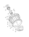
スプール4は、図4及び図5に示すように、浅溝形のものである。スプール4は、スプール軸16の先端部に回転不能かつ着脱可能に連結されている。スプール軸16の先端部外周面には、平行な面取り部を有する回り止め部16aと、雄ねじ部16bと、が形成されている。スプール4は、雄ねじ部16bに螺合するスプールつまみ54によりスプール軸16の先端部に着脱可能に固定されている。また、スプール4は、背面にねじ止めされた回り止め部材55によりスプール軸16に対して回り止めされる。回り止め部材55は、断面視正六角形の外周面55aを有している。この外周面55aは、スプール軸16に回転不能に装着された有底筒状の音出し部材56の内周面に係合する。音出し部材56は、円形のスプール受け57に接触している。これらの音出し部材56及びスプール受け57は、回り止め部16aに係合してスプール軸16に回転不能に装着される。スプール受け57は、回り止め部16aのスプール軸16の外周面との間の段差で軸方向後方への移動が規制される。なお、音出し部材56は、第1実施形態では、スプール4がスプール軸16に対して回転しないので発音機構としては機能しない。
<Spool configuration>
As shown in FIGS. 4 and 5, the
スプール4は、外周に釣り糸が巻き付けられる糸巻胴部4aと、糸巻胴部4aの後端部に糸巻胴部4aより僅かに大径に形成された後フランジ部4bと、糸巻胴部4aの先端部に糸巻胴部4aより僅かに大径に形成された前フランジ部4cと、後フランジ部の外周側に筒状に一体形成されたスカート部4dと、を有している。これらの各部は、例えば、ガラス短繊維で強化されたポリアミド樹脂等の合成樹脂製であり、射出成形により形成されている。
The
糸巻胴部4aは、ロータ3の支持部30の外周側に配置されている。糸巻胴部4aは、周方向に間隔を隔てて配置された複数条の連結部25と、前フランジ部4cと後フランジ部4bとの間で連結部25の内周部を連結する連結筒部26と、を有している。また、糸巻胴部4aは、前フランジ部4c形成部分の内周部に形成された円板状の前壁部27と、貫通孔28aを有し前壁部27の内周部に設けられたボス部28と、を有している。前壁部27の後面には、ボス部28の外周部から放射状に延びる補強用の複数(例えば4つ)のリブ27aが後方に突出して形成されている。ボス部28の貫通孔28aに、スプール軸16の外周面が回転自在に嵌合している。また、ボス部28の背面に回り止め部材55が固定されている。
The bobbin trunk 4 a is disposed on the outer peripheral side of the
連結部25は、前フランジ部4cと後フランジ部4bとを連結するように前後方向に沿って形成されている。複数条の連結部25は、糸巻胴部4aと前フランジ部4c及び後フランジ部4bとの肉厚の変動を抑えるために設けられている。連結部25は、前後方向において、直径が同一の円弧面で外周面が構成されている。第1実施形態では、連結部25は、例えば16条設けられている。
The connecting
連結筒部26の内周面には、成形時の金型の離脱を良好にするために抜きテーパが形成されている。したがって、スプール軸に対して0.5度から2度程度の角度のテーパ面となっており、後方側が前方側に比べて内径が大きくなっている。
A punching taper is formed on the inner peripheral surface of the connecting
後フランジ部4bは、前フランジ部4cより僅かに大径に形成されている。後フランジ部4bは、糸巻胴部4aと実質的に直交するように円板状に形成されている。前フランジ部4cは、糸巻胴部4a側に前方に向かって傾斜するテーパ面を有している。前フランジ部4cの前面には、前フランジ部4cの肉厚を調整するための第1肉盗み部4gが環状に凹んで形成されている。第1肉盗み部4gは、前フランジ部4cの前面全体に形成されているが、全面に周方向に間隔を隔て形成してもよい。
The
スカート部4dには、釣り糸を係止する釣り糸係止部4eが設けられている。釣り糸係止部4eは、U字状に凹んだ部分に配置されている。釣り糸係止部4eの装着部分を除くスカート部4dの外周面には、軽量化を図るとともに肉厚を調整するための矩形に凹んだ複数(例えば15個)の第2肉盗み部4fが周方向に間隔を隔てて形成されている。第2肉盗み部4fの形成部分には、環状の凹み部4hが形成されている。この凹み部4hにより、糸巻胴部4aからスカート部4dに釣り糸が侵入しても、侵入した釣り糸が凹み部4hで引っ掛かってそれ以上後方に移動しにくくなくなる。このため、スプール4から後方への糸落ちが生じにくくなる。
The
このような構成のスプール4では、複数条の連結部25により、前フランジ部4c及び後フランジ部4bに対して肉厚の変動が少なくなるように調整することができる。このため、スプール4の外側部でのシンクマークの発生を抑えることができる。
In the
<第2実施形態>
第1実施形態では、スプール4の糸巻胴部4aの連結部25を前後方向に沿って配置した。しかし、第2実施形態では、図6に示すように、スプール104の糸巻胴部104aの連結部125を前後方向と交差させて斜めに形成している。具体的には、連結部125は、前フランジ部4cとの連結部分と後フランジ部4bとの連結部分との周方向の位相が、例えば22.5度ずれて配置されている。連結筒部126は、連結部125の内周部を連結する。その他のスプールの構成は、第1実施形態と同様なため説明を省略する。
Second Embodiment
In the first embodiment, the connecting
<第3実施形態>
図7に示すように、第3実施形態に係るスプール204の糸巻胴部204aは、スプール軸16と直交して配置され連結部225を周方向に連結する少なくとも一つの環状部229をさらに有している。第3実施形態では、環状部229は、前後方向に間隔を隔てて3個設けられている。連結筒部226は、連結部225の内周部を連結する。その他のスプールの構成は、第1実施形態と同様なため説明を省略する。
<Third Embodiment>
As shown in FIG. 7, the
<第4実施形態>
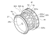
図8に示すように、第4実施形態に係るスプール304の糸巻胴部304aは、複数条の連結部325と、連結筒部326と、を有している。連結部325は、前後方向と交差する第1方向に沿って斜めに配置される複数条の第1連結部325aと、第1方向と交差する第2方向に沿って斜めに配置される複数条の第2連結部325bと、を有している。第1連結部325aと第2連結部325bとは、逆方向に斜めに配置されている。したがって、第1連結部325aと第2連結部325bは、前後方向の途中で交差している。このため、交差部分325cにより連結部325が補強され、周方向の剛性を高めることができる。連結筒部326は、連結部325の内周部を連結する。その他のスプールの構成は、第1実施形態と同様なため説明を省略する。
<Fourth embodiment>
As shown in FIG. 8, the
<第5実施形態>
図9に示すように、第5実施形態のスプール404の糸巻胴部404aは、第1実施形態のスプール4に対して、連結筒部26が形成されていない。連結部425は、第1実施形態の連結筒部26の内周面が形成されている部分までの厚みを有している。
<Fifth Embodiment>
As shown in FIG. 9, the
また、スカート部404dに形成された肉盗み部404fがスカート部404dの内外周面を貫通して形成されている。このようにスカート部404dの内外周面を貫通して肉盗み部404fを形成すると、スプール404をさらに軽量化できる。その他のスプールの構成は、第1実施形態と同様なため説明を省略する。
Further, a
<第6実施形態>
図10に示すように、第6実施形態のスプール504の糸巻胴部504aは、第3実施形態の環状部229を有する糸巻胴部204aに対して、連結筒部226が形成されていない。したがって、第5実施形態と同様に連結部525及び環状部529は、連結筒部226の内周面が形成された部分までの厚みを有している。また、肉盗み部504fは、第5実施形態と同様に、スカート部504dの内外周面を貫通して形成されている。その他のスプールの構成は、第1実施形態と同様なため説明を省略する。
<Sixth Embodiment>
As shown in FIG. 10, the
<第7実施形態>
図11に示すように、第7実施形態のスプール604の糸巻胴部604aは、第4実施形態の第1連結部325a及び第2連結部325bが形成された連結部325を有する糸巻胴部304aに対して、連結筒部326が形成されていない。したがって、第5実施形態と同様に第1連結部625a及び第2連結部625bを有する連結部625は、連結筒部326の内周面が形成された部分までの厚みを有している。肉盗み部4fを含むその他のスプールの構成は、第1実施形態と同様なため説明を省略する。
<Seventh embodiment>
As shown in FIG. 11, the
<第8実施形態>
図12に示すように、第8実施形態のスプール704の糸巻胴部704aは、第7実施形態の第1連結部625a及び第2連結部625bが形成された連結部625を有する糸巻胴部604aに対して、環状部729が形成されている。したがって、第7実施形態と同様に第1連結部725a及び第2連結部725bを有する連結部725並びに環状部729は、第7実施形態の連結部625と同じ厚みを有している。肉盗み部4fを含むその他のスプールの構成は、第1実施形態と同様なため説明を省略する。
<Eighth Embodiment>
As shown in FIG. 12, the
<特徴>
(A)スピニングリールのスプール4(104,204・・・704)は、スピニングリールのリール本体2に前後移動可能に設けられたスプール軸16に装着され釣り糸を巻き付けるためのものである。スプール4(104,204・・・704)は、前フランジ部4cと、後フランジ部4bと、糸巻胴部4a(104a,204a・・・704a)と、を有している。後フランジ部4bは、前フランジ部4cの後方に配置されている。糸巻胴部4a(104a,204a・・・704a)は、前フランジ部4cと後フランジ部4bとを連結するように周方向に間隔を隔てて配置された複数条の連結部25(125,225・・・725)を有し、前フランジ部4c及び後フランジ部4bより小径に両者と一体形成されている。
<Features>
(A) The spinning reel spool 4 (104, 204,... 704) is mounted on a
このスプールでは、糸巻胴部4a(104a,204a・・・704a)は、複数条の連結部25(125,225・・・725)を有している。連結部25(125,225・・・725)が前フランジ部4cと後フランジ部4bとを連結している。この複数条の連結部25(125,225・・・725)により、前フランジ部4c及び後フランジ部4bに対して糸巻胴部4a(104a,204a・・・704a)の肉厚の変動が少なくなるように調整することができる。ここでは、糸巻胴部4a(104a,204a・・・704a)を周方向に間隔を隔てて配置された複数条の連結部25(125,225・・・725)で構成することにより、前フランジ部4c及び後フランジ部4bと糸巻胴部4a(104a,204a・・・704a)との肉厚の変動を調整できる。このため、スプール4(104,204・・・704)の外側面でのシンクマークの発生を抑えることができる。
In this spool, the bobbin trunk 4a (104a, 204a,... 704a) has a plurality of connecting portions 25 (125, 225,... 725). The connecting portion 25 (125, 225,... 725) connects the
(B)スプール4(104,204,304)において、糸巻胴部4a(104a,204a,304a)は、複数条の連結部25(125,225,325)の内周部を連結する連結筒部26(126,226,326)をさらに有する。この場合には、連結筒部26(126,226,326)で連結部25(125,225,325)の内周部を連結しているので、糸巻胴部4a(104a,204a,304a)の周方向の剛性が高くなる。 (B) In the spool 4 (104, 204, 304), the bobbin trunk 4a (104a, 204a, 304a) is a connecting cylinder portion that connects the inner peripheral portions of the plurality of connecting portions 25 (125, 225, 325). 26 (126, 226, 326). In this case, since the inner peripheral part of the connecting part 25 (125, 225, 325) is connected by the connecting cylinder part 26 (126, 226, 326), the bobbin trunk 4a (104a, 204a, 304a) The circumferential rigidity increases.
(C)スプール4(204,404,504)において、複数条の連結部25(225,425,525)は、前後方向に沿って配置されている。この場合には、連結部25(225,425,525)の構造が簡素になり、連結部25(225,425,525)を含むスプール4(204,404,504)を射出成形により製造しやすくなる。 (C) In the spool 4 (204, 404, 504), the plurality of connecting portions 25 (225, 425, 525) are arranged along the front-rear direction. In this case, the structure of the connecting portion 25 (225, 425, 525) is simplified, and the spool 4 (204, 404, 504) including the connecting portion 25 (225, 425, 525) can be easily manufactured by injection molding. Become.
(D)スプール104(304,604,704)において、複数条の連結部125(325,625,725)は、前後方向と交差するように斜めに配置されている。この場合には、連結部125(325,625,725)が斜めに配置されるので、糸巻胴部104a(304a,604a,704a)の周方向の剛性がさらに高くなる。
(D) In the spool 104 (304, 604, 704), the plurality of connecting portions 125 (325, 625, 725) are arranged obliquely so as to intersect the front-rear direction. In this case, since the connecting portion 125 (325, 625, 725) is disposed obliquely, the circumferential rigidity of the
(E)スプール604(704)において、複数条の連結部625(725)は、前後方向と交差する第1方向に沿って斜めに配置される第1連結部625a(725a)と、第1方向と交差する第2方向に沿って斜めに配置される第2連結部625b(725b)と、を有している。この場合には、第1方向と第2方向とに斜めに交差する第1連結部625a(725a)と第2連結部625b(725b)とで連結部625(725)が構成される。このため、第1連結部625a(725a)と第2連結部625b(725b)との複数の交差部分が周方向及び前後方向に形成される。この結果、糸巻胴部604a(704a)の周方向の剛性がさらに高くなる。
(E) In the spool 604 (704), the plurality of connecting portions 625 (725) includes a first connecting
(F)スプール204(504,704)において、糸巻胴部204a(504a,704a)は、スプール軸16と直交して配置され連結部225(525,725)を周方向に連結する少なくとも一つの環状部229(529,729)をさらに有する。この場合は、周方向に間隔を隔てて配置された連結部225(525,725)が環状部229(529,729)により周方向に連結されるので、糸巻胴部204a(504a,704a)の周方向の剛性がさらに高くなる。
(F) In the spool 204 (504, 704), the
(G)スプール4(104,204・・・704)において、後フランジ部4bの外周側に筒状に一体形成されたスカート部4d(404d)をさらに備える。この場合には、筒状のスカート部4d(404d)によりスプール4(104,204・・・704)全体の剛性を高めることができる。
(G) The spool 4 (104, 204... 704) further includes a
<他の実施形態>
以上、本発明の一実施形態について説明したが、本発明は上記実施形態に限定されるものではなく、発明の要旨を逸脱しない範囲で種々の変更が可能である。
<Other embodiments>
As mentioned above, although one Embodiment of this invention was described, this invention is not limited to the said embodiment, A various change is possible in the range which does not deviate from the summary of invention.
(a)前記実施形態では、連結部を前後方向に沿って又は前後方向と交差するように直線的な形状にしたが、連結部の形成方向は、前フランジ部と後フランジ部とを連結できればどのような形状でもよい。例えば、前フランジ部と後フランジ部とを屈曲した複数条の直線又は湾曲した複数条の曲線(例えばスパイラル形状の曲線)で連結してもよい。 (A) In the said embodiment, although the connection part was made into the linear shape so that it might cross | intersect the front-back direction or the front-back direction, if the formation direction of a connection part can connect a front flange part and a rear flange part, Any shape is acceptable. For example, the front flange portion and the rear flange portion may be connected by a plurality of straight lines or a plurality of curved curves (for example, a spiral curve).
(b)前記実施形態では、ドラグ機構を有さない投げ釣り用のスピニングリールの浅溝形のスプールを例示したが、ドラグ機構を有するスプール等のすべての形式のスピニングリールのスプールに本発明を適用できる。 (B) In the above embodiment, the shallow groove type spool of the spinning reel for throwing fishing without the drag mechanism is exemplified, but the present invention is applied to all types of spinning reel spools such as a spool having the drag mechanism. Applicable.
(c)前記実施形態では、スプール表面に何も処理をしていないが、スプールの糸巻胴部及び前後のフランジ部等の釣り糸が接触する部分に硬質メッキやイオンプレーティング被膜等の硬質被膜を形成してもよい。 (C) In the above embodiment, the spool surface is not subjected to any treatment, but a hard coating such as hard plating or ion plating coating is applied to the portion of the spool where the fishing line contacts, such as the bobbin trunk and the front and rear flanges. It may be formed.
(d)前記実施形態では、糸巻胴部の内周側にロータの支持部が収納されるスプールを例に本発明を説明したが、スカート部の内周側にロータの支持部が収納されるスプールにも本発明を適用できる。 (D) In the above embodiment, the present invention has been described by taking the spool in which the support portion of the rotor is housed on the inner peripheral side of the bobbin trunk as an example, but the support portion of the rotor is housed on the inner peripheral side of the skirt portion The present invention can also be applied to a spool.
2 リール本体
4 スプール
4a 糸巻胴部
4b 後フランジ部
4c 前フランジ部
4d スカート部
4e 釣り糸係止部
16 スプール軸
25 連結部
26 連結筒部
104 スプール
104a 糸巻胴部
125 連結部
126 連結筒部
204 スプール
204a 糸巻胴部
225 連結部
226 連結筒部
229 環状部
304 スプール
304a 糸巻胴部
325 連結部
325a 第1連結部
325b 第2連結部
326 連結筒部
404 スプール
404a 糸巻胴部
404d スカート部
425 連結部
504 スプール
504a 糸巻胴部
525 連結部
529 環状部
604 スプール
604a 糸巻胴部
625 連結部
625a 第1連結部
625b 第2連結部
704 スプール
704a 糸巻胴部
725 連結部
725a 第1連結部
725b 第2連結部
729 環状部
2
Claims (6)
前フランジ部と、
前記前フランジ部の後方に配置された後フランジ部と、
前記前フランジ部と前記後フランジ部とを連結するように周方向に間隔を隔てて配置された複数条の連結部を有し、前記前フランジ部及び前記後フランジ部より小径に両者と一体形成された糸巻胴部と、を備え、
前記糸巻胴部は、前記前フランジ部形成部分の内周部に形成された円板状の前壁部と、貫通孔を有し前記前壁部の内周部に設けられたボス部と、を有し、
前記前壁部の後面には、前記ボス部の外周部から放射状に延びる補強用の複数のリブが後方に突出して形成されており、
前記糸巻胴部は、前記前フランジ部と前記後フランジ部との間で前記複数条の連結部の内周部を連結する連結筒部をさらに有し、
前記連結筒部の内周面には、抜きテーパが形成されている、
スピニングリールのスプール。 A spool made of synthetic resin, which is formed by injection molding as a whole, is mounted on a spool shaft provided on a reel body of a spinning reel so as to be movable back and forth and winds a fishing line,
Front flange,
A rear flange portion disposed behind the front flange portion;
It has a plurality of connecting portions arranged at intervals in the circumferential direction so as to connect the front flange portion and the rear flange portion, and is integrally formed with both at a smaller diameter than the front flange portion and the rear flange portion. A wound bobbin body ,
The bobbin trunk includes a disc-shaped front wall portion formed on the inner peripheral portion of the front flange portion forming portion, a boss portion having a through hole and provided on the inner peripheral portion of the front wall portion, Have
A plurality of reinforcing ribs extending radially from the outer peripheral portion of the boss portion are formed on the rear surface of the front wall portion so as to protrude rearward.
The bobbin trunk further includes a connecting cylinder portion that connects inner peripheral portions of the plurality of connecting portions between the front flange portion and the rear flange portion,
On the inner peripheral surface of the connecting cylinder part, a punching taper is formed,
Spinning reel spool.
前記前後方向と交差する第1方向に沿って斜めに配置される複数条の第1連結部と、
前記第1方向と交差する第2方向に沿って斜めに配置される複数条の第2連結部と、
を有している、請求項3に記載のスピニングリールのスプール。 The plurality of connecting portions are
A plurality of first connecting portions disposed obliquely along a first direction intersecting the front-rear direction;
A plurality of second connecting portions disposed obliquely along a second direction intersecting the first direction;
The spinning reel spool according to claim 3 , comprising:
Priority Applications (5)
| Application Number | Priority Date | Filing Date | Title |
|---|---|---|---|
| JP2010114385A JP5680335B2 (en) | 2010-05-18 | 2010-05-18 | Spinning reel spool |
| EP11159490.9A EP2387881B1 (en) | 2010-05-18 | 2011-03-24 | Spinning reel spool |
| TW100110413A TWI566695B (en) | 2010-05-18 | 2011-03-25 | Spinning reel spool |
| KR1020110036314A KR101740930B1 (en) | 2010-05-18 | 2011-04-19 | Spinning reel spool |
| CN201110104003.6A CN102246730B (en) | 2010-05-18 | 2011-04-22 | Spinning reel spool |
Applications Claiming Priority (1)
| Application Number | Priority Date | Filing Date | Title |
|---|---|---|---|
| JP2010114385A JP5680335B2 (en) | 2010-05-18 | 2010-05-18 | Spinning reel spool |
Publications (3)
| Publication Number | Publication Date |
|---|---|
| JP2011239722A JP2011239722A (en) | 2011-12-01 |
| JP2011239722A5 JP2011239722A5 (en) | 2013-06-27 |
| JP5680335B2 true JP5680335B2 (en) | 2015-03-04 |
Family
ID=44475092
Family Applications (1)
| Application Number | Title | Priority Date | Filing Date |
|---|---|---|---|
| JP2010114385A Active JP5680335B2 (en) | 2010-05-18 | 2010-05-18 | Spinning reel spool |
Country Status (5)
| Country | Link |
|---|---|
| EP (1) | EP2387881B1 (en) |
| JP (1) | JP5680335B2 (en) |
| KR (1) | KR101740930B1 (en) |
| CN (1) | CN102246730B (en) |
| TW (1) | TWI566695B (en) |
Families Citing this family (3)
| Publication number | Priority date | Publication date | Assignee | Title |
|---|---|---|---|---|
| JP5779516B2 (en) * | 2012-02-06 | 2015-09-16 | グローブライド株式会社 | Fishing line winding spool and fishing reel equipped with this spool |
| JP6462382B2 (en) * | 2015-01-29 | 2019-01-30 | 株式会社シマノ | Engaging pin and reciprocating mechanism of fishing reel having engaging pin |
| CN112262828A (en) * | 2020-11-19 | 2021-01-26 | 许一帆 | Positioning wire clamping device capable of achieving buffering |
Family Cites Families (18)
| Publication number | Priority date | Publication date | Assignee | Title |
|---|---|---|---|---|
| JPS4970088U (en) * | 1972-10-03 | 1974-06-18 | ||
| JPH0445506Y2 (en) * | 1985-07-22 | 1992-10-26 | ||
| JPH0452470U (en) * | 1990-09-07 | 1992-05-01 | ||
| JP3137902B2 (en) | 1996-05-31 | 2001-02-26 | 株式会社熊谷組 | Drilling rig for underground diaphragm wall construction |
| JP3033414U (en) * | 1996-07-10 | 1997-01-28 | ダイワ精工株式会社 | Spinning reel for fishing |
| JP3443811B2 (en) * | 1997-01-28 | 2003-09-08 | ダイワ精工株式会社 | Spinning reel for fishing |
| JPH1146635A (en) * | 1997-08-08 | 1999-02-23 | Shimano Inc | Spool for fishing reel |
| JP3512683B2 (en) * | 1999-08-04 | 2004-03-31 | ダイワ精工株式会社 | Fishing reel |
| JP2001148973A (en) * | 1999-11-26 | 2001-06-05 | Shimano Inc | Spool of spinning reel |
| JP2004081097A (en) * | 2002-08-27 | 2004-03-18 | Shimano Inc | Sounding mechanism of spinning reel |
| JP3981325B2 (en) * | 2002-12-06 | 2007-09-26 | 株式会社シマノ | Spool support structure for spinning reel |
| JP3958737B2 (en) | 2003-12-03 | 2007-08-15 | 弘孝 寺田 | Fishing reel spool |
| JP4476790B2 (en) * | 2004-11-25 | 2010-06-09 | グローブライド株式会社 | Fishing spinning reel |
| JP4795135B2 (en) * | 2006-06-27 | 2011-10-19 | グローブライド株式会社 | Fishing spinning reel spool |
| JP3137902U (en) * | 2007-09-28 | 2007-12-13 | 世淵 葉 | Fishing reel |
| JP5205121B2 (en) * | 2008-04-30 | 2013-06-05 | 株式会社シマノ | Spinning reel spool |
| KR20100040393A (en) * | 2008-10-10 | 2010-04-20 | 강석운 | Fly reel |
| CN201388450Y (en) * | 2009-02-23 | 2010-01-27 | 威海光威精密机械有限公司 | Coiling wheel of fishing coil wheel |
-
2010
- 2010-05-18 JP JP2010114385A patent/JP5680335B2/en active Active
-
2011
- 2011-03-24 EP EP11159490.9A patent/EP2387881B1/en active Active
- 2011-03-25 TW TW100110413A patent/TWI566695B/en active
- 2011-04-19 KR KR1020110036314A patent/KR101740930B1/en active IP Right Grant
- 2011-04-22 CN CN201110104003.6A patent/CN102246730B/en not_active Expired - Fee Related
Also Published As
| Publication number | Publication date |
|---|---|
| KR101740930B1 (en) | 2017-06-15 |
| CN102246730A (en) | 2011-11-23 |
| KR20110127065A (en) | 2011-11-24 |
| EP2387881B1 (en) | 2015-07-29 |
| TW201200013A (en) | 2012-01-01 |
| EP2387881A1 (en) | 2011-11-23 |
| CN102246730B (en) | 2014-11-26 |
| TWI566695B (en) | 2017-01-21 |
| JP2011239722A (en) | 2011-12-01 |
Similar Documents
| Publication | Publication Date | Title |
|---|---|---|
| JP5143757B2 (en) | Fishing reel screw shaft and fishing reel reciprocating mechanism using the same | |
| KR101293173B1 (en) | Reciprocating mechanism for spinning reel | |
| JP2010166882A5 (en) | ||
| JP4045167B2 (en) | Spinning reel handle assembly | |
| KR20090028459A (en) | Spinning reel | |
| KR20110086496A (en) | Spinning reel spool support structure | |
| JP5680335B2 (en) | Spinning reel spool | |
| KR102002854B1 (en) | Handle assembly for spinning reel | |
| JP4015957B2 (en) | Spinning reel handle assembly | |
| US8939391B2 (en) | Spinning reel body and spinning reel | |
| JP5869240B2 (en) | Handle handle for fishing reel | |
| KR20040036639A (en) | Reel unit for spinning reel | |
| JP5010860B2 (en) | Handle handle for fishing reel | |
| JP2004236571A (en) | Handle fixing structure of fishing reel | |
| JP4476128B2 (en) | Spinning reel master gear | |
| JP2010172272A (en) | Reciprocating movement mechanism of spinning reel | |
| JP2008022756A (en) | Spinning reel and its handle assembly | |
| JP6376756B2 (en) | Fishing reel reciprocating mechanism | |
| JP2009065933A (en) | Spinning reel | |
| US10028494B2 (en) | Spinning reel rotor and spinning reel | |
| JP2009065935A (en) | Rotor and rotor main body of spinning reel | |
| JP2003079287A (en) | Structure for attaching handle of spinning reel | |
| JP2015128403A5 (en) | ||
| JP4827242B2 (en) | Fishing spinning reel | |
| JP4121871B2 (en) | Spinning reel body |
Legal Events
| Date | Code | Title | Description |
|---|---|---|---|
| A521 | Request for written amendment filed |
Free format text: JAPANESE INTERMEDIATE CODE: A523 Effective date: 20130515 |
|
| A621 | Written request for application examination |
Free format text: JAPANESE INTERMEDIATE CODE: A621 Effective date: 20130515 |
|
| A977 | Report on retrieval |
Free format text: JAPANESE INTERMEDIATE CODE: A971007 Effective date: 20140210 |
|
| A131 | Notification of reasons for refusal |
Free format text: JAPANESE INTERMEDIATE CODE: A131 Effective date: 20140218 |
|
| A521 | Request for written amendment filed |
Free format text: JAPANESE INTERMEDIATE CODE: A523 Effective date: 20140507 |
|
| TRDD | Decision of grant or rejection written | ||
| A01 | Written decision to grant a patent or to grant a registration (utility model) |
Free format text: JAPANESE INTERMEDIATE CODE: A01 Effective date: 20141209 |
|
| A61 | First payment of annual fees (during grant procedure) |
Free format text: JAPANESE INTERMEDIATE CODE: A61 Effective date: 20150107 |
|
| R150 | Certificate of patent or registration of utility model |
Ref document number: 5680335 Country of ref document: JP Free format text: JAPANESE INTERMEDIATE CODE: R150 |
|
| R250 | Receipt of annual fees |
Free format text: JAPANESE INTERMEDIATE CODE: R250 |
|
| R250 | Receipt of annual fees |
Free format text: JAPANESE INTERMEDIATE CODE: R250 |
|
| R250 | Receipt of annual fees |
Free format text: JAPANESE INTERMEDIATE CODE: R250 |
|
| R250 | Receipt of annual fees |
Free format text: JAPANESE INTERMEDIATE CODE: R250 |
|
| R250 | Receipt of annual fees |
Free format text: JAPANESE INTERMEDIATE CODE: R250 |
|
| R250 | Receipt of annual fees |
Free format text: JAPANESE INTERMEDIATE CODE: R250 |
|
| S111 | Request for change of ownership or part of ownership |
Free format text: JAPANESE INTERMEDIATE CODE: R313113 |
|
| R350 | Written notification of registration of transfer |
Free format text: JAPANESE INTERMEDIATE CODE: R350 |
|
| R250 | Receipt of annual fees |
Free format text: JAPANESE INTERMEDIATE CODE: R250 |