JP5680053B2 - Gas turbine with improved partial load emission characteristics - Google Patents
Gas turbine with improved partial load emission characteristics Download PDFInfo
- Publication number
- JP5680053B2 JP5680053B2 JP2012502550A JP2012502550A JP5680053B2 JP 5680053 B2 JP5680053 B2 JP 5680053B2 JP 2012502550 A JP2012502550 A JP 2012502550A JP 2012502550 A JP2012502550 A JP 2012502550A JP 5680053 B2 JP5680053 B2 JP 5680053B2
- Authority
- JP
- Japan
- Prior art keywords
- turbine
- combustor
- fuel
- load
- burner
- Prior art date
- Legal status (The legal status is an assumption and is not a legal conclusion. Google has not performed a legal analysis and makes no representation as to the accuracy of the status listed.)
- Expired - Fee Related
Links
- 230000036961 partial effect Effects 0.000 title claims description 43
- 239000000446 fuel Substances 0.000 claims description 136
- 238000001816 cooling Methods 0.000 claims description 55
- 238000000034 method Methods 0.000 claims description 49
- 230000001105 regulatory effect Effects 0.000 claims description 32
- 238000002485 combustion reaction Methods 0.000 claims description 28
- 238000000926 separation method Methods 0.000 claims description 26
- 230000002829 reductive effect Effects 0.000 claims description 25
- 238000009826 distribution Methods 0.000 claims description 19
- 230000009467 reduction Effects 0.000 claims description 8
- 230000001419 dependent effect Effects 0.000 claims description 3
- 230000006835 compression Effects 0.000 claims 1
- 238000007906 compression Methods 0.000 claims 1
- 239000003570 air Substances 0.000 description 111
- 239000007789 gas Substances 0.000 description 76
- 239000000567 combustion gas Substances 0.000 description 25
- 101100152436 Saccharomyces cerevisiae (strain ATCC 204508 / S288c) TAT2 gene Proteins 0.000 description 23
- 101100457843 Schizosaccharomyces pombe (strain 972 / ATCC 24843) tit1 gene Proteins 0.000 description 11
- 101000969630 Homo sapiens Monocarboxylate transporter 10 Proteins 0.000 description 8
- 102100021425 Monocarboxylate transporter 10 Human genes 0.000 description 8
- 238000007710 freezing Methods 0.000 description 6
- 230000008859 change Effects 0.000 description 5
- 230000008901 benefit Effects 0.000 description 4
- 238000006243 chemical reaction Methods 0.000 description 4
- 238000013461 design Methods 0.000 description 4
- 230000010349 pulsation Effects 0.000 description 3
- 238000011084 recovery Methods 0.000 description 3
- 230000006978 adaptation Effects 0.000 description 2
- 230000033228 biological regulation Effects 0.000 description 2
- 239000003426 co-catalyst Substances 0.000 description 2
- 238000007796 conventional method Methods 0.000 description 2
- 230000003247 decreasing effect Effects 0.000 description 2
- 230000008014 freezing Effects 0.000 description 2
- 229930195733 hydrocarbon Natural products 0.000 description 2
- 150000002430 hydrocarbons Chemical class 0.000 description 2
- 238000002347 injection Methods 0.000 description 2
- 239000007924 injection Substances 0.000 description 2
- 239000007788 liquid Substances 0.000 description 2
- 238000004519 manufacturing process Methods 0.000 description 2
- VNWKTOKETHGBQD-UHFFFAOYSA-N methane Chemical compound C VNWKTOKETHGBQD-UHFFFAOYSA-N 0.000 description 2
- 238000002156 mixing Methods 0.000 description 2
- 230000002265 prevention Effects 0.000 description 2
- XLYOFNOQVPJJNP-UHFFFAOYSA-N water Substances O XLYOFNOQVPJJNP-UHFFFAOYSA-N 0.000 description 2
- 239000004215 Carbon black (E152) Substances 0.000 description 1
- UGFAIRIUMAVXCW-UHFFFAOYSA-N Carbon monoxide Chemical compound [O+]#[C-] UGFAIRIUMAVXCW-UHFFFAOYSA-N 0.000 description 1
- 230000004913 activation Effects 0.000 description 1
- 239000012080 ambient air Substances 0.000 description 1
- 230000002528 anti-freeze Effects 0.000 description 1
- 229910002091 carbon monoxide Inorganic materials 0.000 description 1
- 230000000295 complement effect Effects 0.000 description 1
- 230000009849 deactivation Effects 0.000 description 1
- 238000011161 development Methods 0.000 description 1
- 238000010586 diagram Methods 0.000 description 1
- 238000010790 dilution Methods 0.000 description 1
- 239000012895 dilution Substances 0.000 description 1
- 230000009977 dual effect Effects 0.000 description 1
- 230000000694 effects Effects 0.000 description 1
- 238000000605 extraction Methods 0.000 description 1
- 239000002737 fuel gas Substances 0.000 description 1
- 230000006872 improvement Effects 0.000 description 1
- 238000010348 incorporation Methods 0.000 description 1
- 238000007689 inspection Methods 0.000 description 1
- 239000000463 material Substances 0.000 description 1
- 230000004048 modification Effects 0.000 description 1
- 238000012986 modification Methods 0.000 description 1
- 239000003345 natural gas Substances 0.000 description 1
- 238000005457 optimization Methods 0.000 description 1
- 238000005086 pumping Methods 0.000 description 1
- 230000000087 stabilizing effect Effects 0.000 description 1
- 230000003068 static effect Effects 0.000 description 1
- 230000001360 synchronised effect Effects 0.000 description 1
- 230000007704 transition Effects 0.000 description 1
- 238000011144 upstream manufacturing Methods 0.000 description 1
- 239000002918 waste heat Substances 0.000 description 1
- 230000003313 weakening effect Effects 0.000 description 1
Images


Classifications
-
- F—MECHANICAL ENGINEERING; LIGHTING; HEATING; WEAPONS; BLASTING
- F02—COMBUSTION ENGINES; HOT-GAS OR COMBUSTION-PRODUCT ENGINE PLANTS
- F02C—GAS-TURBINE PLANTS; AIR INTAKES FOR JET-PROPULSION PLANTS; CONTROLLING FUEL SUPPLY IN AIR-BREATHING JET-PROPULSION PLANTS
- F02C9/00—Controlling gas-turbine plants; Controlling fuel supply in air- breathing jet-propulsion plants
- F02C9/26—Control of fuel supply
-
- F—MECHANICAL ENGINEERING; LIGHTING; HEATING; WEAPONS; BLASTING
- F02—COMBUSTION ENGINES; HOT-GAS OR COMBUSTION-PRODUCT ENGINE PLANTS
- F02C—GAS-TURBINE PLANTS; AIR INTAKES FOR JET-PROPULSION PLANTS; CONTROLLING FUEL SUPPLY IN AIR-BREATHING JET-PROPULSION PLANTS
- F02C6/00—Plural gas-turbine plants; Combinations of gas-turbine plants with other apparatus; Adaptations of gas-turbine plants for special use
- F02C6/003—Gas-turbine plants with heaters between turbine stages
-
- F—MECHANICAL ENGINEERING; LIGHTING; HEATING; WEAPONS; BLASTING
- F23—COMBUSTION APPARATUS; COMBUSTION PROCESSES
- F23C—METHODS OR APPARATUS FOR COMBUSTION USING FLUID FUEL OR SOLID FUEL SUSPENDED IN A CARRIER GAS OR AIR
- F23C6/00—Combustion apparatus characterised by the combination of two or more combustion chambers or combustion zones, e.g. for staged combustion
- F23C6/04—Combustion apparatus characterised by the combination of two or more combustion chambers or combustion zones, e.g. for staged combustion in series connection
- F23C6/042—Combustion apparatus characterised by the combination of two or more combustion chambers or combustion zones, e.g. for staged combustion in series connection with fuel supply in stages
-
- F—MECHANICAL ENGINEERING; LIGHTING; HEATING; WEAPONS; BLASTING
- F23—COMBUSTION APPARATUS; COMBUSTION PROCESSES
- F23N—REGULATING OR CONTROLLING COMBUSTION
- F23N1/00—Regulating fuel supply
- F23N1/02—Regulating fuel supply conjointly with air supply
- F23N1/022—Regulating fuel supply conjointly with air supply using electronic means
-
- F—MECHANICAL ENGINEERING; LIGHTING; HEATING; WEAPONS; BLASTING
- F23—COMBUSTION APPARATUS; COMBUSTION PROCESSES
- F23R—GENERATING COMBUSTION PRODUCTS OF HIGH PRESSURE OR HIGH VELOCITY, e.g. GAS-TURBINE COMBUSTION CHAMBERS
- F23R7/00—Intermittent or explosive combustion chambers
-
- F—MECHANICAL ENGINEERING; LIGHTING; HEATING; WEAPONS; BLASTING
- F23—COMBUSTION APPARATUS; COMBUSTION PROCESSES
- F23N—REGULATING OR CONTROLLING COMBUSTION
- F23N2237/00—Controlling
- F23N2237/02—Controlling two or more burners
-
- F—MECHANICAL ENGINEERING; LIGHTING; HEATING; WEAPONS; BLASTING
- F23—COMBUSTION APPARATUS; COMBUSTION PROCESSES
- F23N—REGULATING OR CONTROLLING COMBUSTION
- F23N2241/00—Applications
- F23N2241/20—Gas turbines
-
- F—MECHANICAL ENGINEERING; LIGHTING; HEATING; WEAPONS; BLASTING
- F23—COMBUSTION APPARATUS; COMBUSTION PROCESSES
- F23R—GENERATING COMBUSTION PRODUCTS OF HIGH PRESSURE OR HIGH VELOCITY, e.g. GAS-TURBINE COMBUSTION CHAMBERS
- F23R2900/00—Special features of, or arrangements for continuous combustion chambers; Combustion processes therefor
- F23R2900/03341—Sequential combustion chambers or burners
-
- Y—GENERAL TAGGING OF NEW TECHNOLOGICAL DEVELOPMENTS; GENERAL TAGGING OF CROSS-SECTIONAL TECHNOLOGIES SPANNING OVER SEVERAL SECTIONS OF THE IPC; TECHNICAL SUBJECTS COVERED BY FORMER USPC CROSS-REFERENCE ART COLLECTIONS [XRACs] AND DIGESTS
- Y02—TECHNOLOGIES OR APPLICATIONS FOR MITIGATION OR ADAPTATION AGAINST CLIMATE CHANGE
- Y02E—REDUCTION OF GREENHOUSE GAS [GHG] EMISSIONS, RELATED TO ENERGY GENERATION, TRANSMISSION OR DISTRIBUTION
- Y02E20/00—Combustion technologies with mitigation potential
- Y02E20/16—Combined cycle power plant [CCPP], or combined cycle gas turbine [CCGT]
Landscapes
- Engineering & Computer Science (AREA)
- Chemical & Material Sciences (AREA)
- Combustion & Propulsion (AREA)
- Mechanical Engineering (AREA)
- General Engineering & Computer Science (AREA)
- Control Of Turbines (AREA)
- Turbine Rotor Nozzle Sealing (AREA)
Description
本発明は、主として、少なくとも1つの圧縮機と、該圧縮機に後置された、第1のタービンに衝突する高温ガスを有する第1の燃焼器と、第1のタービンに後置された、第2のタービンに衝突する高温ガスを有する第2の燃焼器とから成るシーケンシャル燃焼式のガスタービンを低COエミッション運転するための方法に関する。 The present invention mainly includes at least one compressor, a first combustor having a hot gas impinging on the first turbine, which is disposed behind the compressor, and a first turbine. The present invention relates to a method for low CO emissions operation of a sequential combustion gas turbine comprising a second combustor having a hot gas impinging on a second turbine.
さらに、本発明は、このような方法を実施するためのガスタービンに関する。 Furthermore, the invention relates to a gas turbine for carrying out such a method.
背景技術
シーケンシャル燃焼式のガスタービン、つまり、再熱式のガスタービンは、かなり以前から商業的に成果を上げて運転されている。シーケンシャル燃焼式のガスタービンでは、圧縮された空気が第1の燃焼器内で燃料と共に燃焼され、高圧タービンと呼ばれる第1のタービンに高温ガスが衝突させられる。高圧タービンから流出させられた高温ガスの温度は、第2の燃焼器において、燃料の再度の添加と燃焼とによって再び上昇させられ、低圧タービンと呼ばれる第2のタービンにこの高温ガスが衝突させられる。
BACKGROUND OF THE INVENTION Sequential combustion gas turbines, or reheat gas turbines, have been operating commercially for quite some time. In a sequential combustion type gas turbine, compressed air is combusted together with fuel in a first combustor, and a hot gas is collided with a first turbine called a high-pressure turbine. In the second combustor, the temperature of the hot gas discharged from the high-pressure turbine is raised again by re-addition and combustion of the fuel, and this hot gas is made to collide with a second turbine called a low-pressure turbine. .
ただ1つの燃焼器を備えた従来のガスタービンに比べて、シーケンシャル燃焼式のガスタービンは、第1の燃焼器と第2の燃焼器とに対する別個の燃料調整の付加的な自由度の点で優れている。さらに、シーケンシャル燃焼式のガスタービンは、まず、第1の燃焼器だけを運転し、負荷がより高くなった場合に初めて第2の燃焼器を作動させる可能性を提供している。これによって、ガスタービンの幅広い運転範囲にわたって良好なエミッション特性を備えたフレキシブルな運転コンセプトが可能となる。 Compared to conventional gas turbines with only one combustor, sequential combustion gas turbines have the additional freedom of separate fuel adjustments for the first and second combustors. Are better. Further, the sequential combustion type gas turbine first operates only the first combustor, and provides the possibility of operating the second combustor only when the load becomes higher. This enables a flexible operating concept with good emission characteristics over a wide operating range of the gas turbine.
過去、開発の主眼は、NOxエミッションの削減および高い部分負荷効率であった。たとえば欧州特許出願公開第0718470号明細書に記載されているような公知の方法により運転されるシーケンシャル燃焼式のガスタービンは、極めて低いNOxエミッションを有していて、卓越した部分負荷効率を実現することができる。
In the past, development has focused on reducing NOx emissions and high partial load efficiency. Sequential combustion gas turbines operated by known methods, for example as described in
しかし、上述した公知の運転コンセプトは、部分負荷が低い場合、特に相対的な負荷の約20%〜50%の範囲において、高いCOエミッション(一酸化炭素エミッション)を招くことがある。 However, the known operating concepts described above can lead to high CO emissions (carbon monoxide emissions) when the partial load is low, especially in the range of about 20% to 50% of the relative load.
この高いCOエミッションは、部分負荷が低い場合に典型的にシーケンシャル燃焼式のガスタービンの第2の燃焼器によって発生させられる。従来、低い部分負荷に際して、この第2の燃焼器は、調節可能な圧縮機案内羽根列が閉鎖されていて、高圧タービンの高温ガス温度またはタービン入口温度が上限値に達した場合に点火される。この点火のためには、第2の燃焼器に最小の燃料流量が供給される。この燃料流量は、典型的には、燃料調整弁の調整特性によって設定される。第1のタービンの高い出口温度に基づき、第2の燃焼器に供給された燃料流量の自己着火が引き起こされる。燃料流量は、負荷にわたる負荷調整のために増加させられる。燃料流量が少ない限り、第2の燃焼器内の高温ガスの温度は著しく上昇させられない。相応して、反応速度が比較的低いままであり、燃焼器内での短い滞留時間に基づき、未燃焼の炭化水素とCOとが生じることがある。この未燃焼の炭化水素とCOとは、特に希薄燃焼時、すなわち、高い空気比λでの燃焼時に生じる。空気比λとは、少なくとも必要となる化学量論的な空気質量に対する、実際に燃焼のために使用される空気質量の比である。空気比λは、空気数、空気比数または空気過剰率とも呼ばれる。 This high CO emissions is typically generated by the second combustor of a sequential combustion gas turbine when the partial load is low. Conventionally, at low part loads, this second combustor is ignited when the adjustable compressor guide vane row is closed and the hot gas temperature or turbine inlet temperature of the high pressure turbine reaches an upper limit. . For this ignition, a minimum fuel flow is supplied to the second combustor. This fuel flow rate is typically set by the adjustment characteristics of the fuel adjustment valve. Based on the high outlet temperature of the first turbine, self-ignition of the fuel flow supplied to the second combustor is caused. The fuel flow rate is increased for load regulation over the load. As long as the fuel flow rate is small, the temperature of the hot gas in the second combustor cannot be significantly increased. Correspondingly, the reaction rate remains relatively low and unburned hydrocarbons and CO may be generated based on the short residence time in the combustor. This unburned hydrocarbon and CO are generated particularly during lean combustion, that is, during combustion at a high air ratio λ. The air ratio λ is the ratio of the air mass actually used for combustion to at least the required stoichiometric air mass. The air ratio λ is also called the air number, the air ratio number, or the excess air ratio.
しかし、フレキシブルな発電プラント運転の範囲内では、低い部分負荷でのより長い運転期間を経過する可能性もますます要求される。より低い部分負荷でのより長い運転は、COエミッションも低いレベルにとどまっている場合にしか実現することができない。従来では、COエミッションの削減のために、CO触媒が使用される。このCO触媒は、高い仕入れコストのほかに、ガスタービンの排ガスシステムにおける圧力損失と、これに相俟った出力・効率損失とに繋がる。 However, within the scope of flexible power plant operation, there is an increasing demand for longer operating periods at low partial loads. Longer operation at lower partial loads can only be achieved if CO emissions remain at a low level. Conventionally, CO catalysts are used to reduce CO emissions. In addition to high purchase costs, this CO catalyst leads to pressure loss in the exhaust system of the gas turbine and power / efficiency loss combined therewith.
発明の開示
本発明の課題は、シーケンシャル燃焼式のガスタービンを運転するための方法ならびにシーケンシャル燃焼式のガスタービンを改良して、COエミッションが削減された運転が可能となるようにすることである。
DISCLOSURE OF THE INVENTION An object of the present invention is to improve a method for operating a sequential combustion gas turbine and a sequential combustion gas turbine to enable operation with reduced CO emissions. .
この課題を解決するために本発明に係る方法によれば、第2の燃焼器の作動中のバーナの空気比を最大の空気比未満に保つ。 In order to solve this problem, according to the method of the present invention, the air ratio of the burner during operation of the second combustor is kept below the maximum air ratio.
本発明に係る方法の有利な態様によれば、負荷増加時には、第2の燃焼器の作動前に、まず、第1のタービンのタービン入口温度を部分負荷限界値に上昇させて、調節可能な圧縮機案内羽根列を開放し、第2の燃焼器の作動のためにまたは第2の燃焼器の作動時に、調節可能な圧縮機案内羽根列を閉鎖して、燃料を第2の燃焼器内に導入する。 According to an advantageous aspect of the method according to the invention, when the load increases, the turbine inlet temperature of the first turbine is first raised to the partial load limit value before the second combustor is activated. The compressor guide vane row is opened and the adjustable compressor guide vane row is closed for the operation of the second combustor or during the operation of the second combustor, so that the fuel is put into the second combustor. To introduce.
本発明に係る方法の有利な態様によれば、負荷減少時には、第2の燃焼器の停止前に、まず、調節可能な圧縮機案内羽根列を閉鎖し、第2の燃焼器の停止時に、調節可能な圧縮機案内羽根列を再び開放する。 According to an advantageous aspect of the method according to the invention, when the load is reduced, before the second combustor is stopped, the adjustable compressor guide vane row is first closed, and when the second combustor is stopped, Open the adjustable compressor guide vane row again.
本発明に係る方法の有利な態様によれば、前記ガスタービンの負荷減少に際して、ヒステリシスを形成するために、第1のタービンのタービン入口温度の部分負荷限界値および開放された調節可能な圧縮機案内羽根列での第1の燃焼器による運転時に達成される負荷未満である負荷時に初めて第2の燃焼器を停止する。 According to an advantageous aspect of the method according to the invention, a partial load limit of the turbine inlet temperature of the first turbine and an open adjustable compressor are provided to form a hysteresis when the load of the gas turbine is reduced. The second combustor is stopped for the first time at a load that is less than the load achieved during operation with the first combustor in the guide vane row.
本発明に係る方法の有利な態様によれば、第2の燃焼器の少なくとも1つのバーナへの燃料供給を前記部分負荷時に停止し、これによって、第2のタービンのタービン入口温度を変えずに、運転中のバーナの空気比を減少させる。 According to an advantageous aspect of the method according to the invention, the fuel supply to the at least one burner of the second combustor is stopped during the partial load, so that the turbine inlet temperature of the second turbine is not changed. Reduce the air ratio of the burner during operation.
本発明に係る方法の有利な態様によれば、まず、分離平面に隣接した少なくとも1つのバーナへの燃料供給を停止する。 According to an advantageous embodiment of the method according to the invention, firstly the fuel supply to at least one burner adjacent to the separation plane is stopped.
本発明に係る方法の有利な態様によれば、停止されるバーナの個数が、負荷に反比例している。 According to an advantageous embodiment of the method according to the invention, the number of burners to be stopped is inversely proportional to the load.
本発明に係る方法の有利な態様によれば、第1のタービンのタービン出口温度および/または第2のタービンのタービン出口温度の前記部分負荷限界値を所定の部分負荷範囲の間に上昇させ、これによって、調節可能な圧縮機案内羽根列の開放をより高い負荷にシフトする。 According to an advantageous aspect of the method according to the invention, the partial load limit value of the turbine outlet temperature of the first turbine and / or the turbine outlet temperature of the second turbine is increased during a predetermined partial load range, This shifts the opening of the adjustable compressor guide vane row to a higher load.
本発明に係る方法の有利な態様によれば、圧縮されたかまたは部分圧縮された圧縮機空気の部分流を膨張させ、吸入空気に混加する。 According to an advantageous embodiment of the method according to the invention, a partial stream of compressed or partially compressed compressor air is expanded and mixed with the intake air.
本発明に係る方法の有利な態様によれば、前記負荷に関連して、少なくとも冷却空気温度および/または少なくとも冷却空気質量流量を調整する。 According to an advantageous embodiment of the method according to the invention, at least the cooling air temperature and / or at least the cooling air mass flow rate are adjusted in relation to the load.
本発明に係る方法の有利な態様によれば、前記負荷に関連して、第1の燃焼器の燃料温度および/または第2の燃焼器の燃料温度を調整する。 According to an advantageous embodiment of the method according to the invention, the fuel temperature of the first combustor and / or the fuel temperature of the second combustor is adjusted in relation to the load.
さらに、前述した課題を解決するために本発明に係るガスタービンによれば、該ガスタービンが、1つの圧縮機と、該圧縮機に後置された、第1のタービンに衝突する高温ガスを有する第1の燃焼器と、第1のタービンに後置された、第2のタービンに衝突する高温ガスを有する第2の燃焼器とを有している。 Furthermore, in order to solve the above-described problem, according to the gas turbine of the present invention, the gas turbine is provided with one compressor and a high-temperature gas that is placed behind the compressor and that collides with the first turbine. A first combustor having a first combustor and a second combustor having a hot gas impinging on a second turbine, followed by a first turbine.
本発明に係るガスタービンの有利な態様によれば、第2の燃焼器の少なくとも1つのバーナに通じる少なくとも1つの燃料管路内に個別切換弁が配置されている。 According to an advantageous embodiment of the gas turbine according to the invention, an individual switching valve is arranged in at least one fuel line leading to at least one burner of the second combustor.
本発明に係るガスタービンの有利な態様によれば、第2の燃焼器の少なくとも1つのバーナに通じる少なくとも1つの燃料管路内に個別調整弁が配置されている。 According to an advantageous embodiment of the gas turbine according to the invention, an individual regulating valve is arranged in at least one fuel line leading to at least one burner of the second combustor.
本発明に係るガスタービンの有利な態様によれば、燃料分配システムが、第1の燃料調整弁と、燃料を第1のバーナ分割グループのバーナに分配するための第1の燃料環状管路と、少なくとも1つの第2の燃料調整弁と、前記燃料を少なくとも1つの第2の分割グループのバーナに分配するための少なくとも1つの第2の燃料環状管路とを有している。 According to an advantageous aspect of the gas turbine according to the invention, the fuel distribution system comprises a first fuel regulating valve and a first fuel annular line for distributing fuel to the burners of the first burner split group. At least one second fuel regulating valve and at least one second fuel annular line for distributing the fuel to at least one second divided group of burners.
本発明に係るガスタービンの有利な態様によれば、高圧圧縮機が、全負荷時の確実な運転のために必要となる圧力比よりも高い圧力比に対して設計されている。 According to an advantageous embodiment of the gas turbine according to the invention, the high-pressure compressor is designed for a pressure ratio that is higher than that required for reliable operation at full load.
本発明に係るガスタービンの有利な態様によれば、タービン出口と排ガス管路とが、最大の全負荷排ガス温度よりも高い第2のタービンのタービン出口温度に対して設計されている。 According to an advantageous embodiment of the gas turbine according to the invention, the turbine outlet and the exhaust gas line are designed for a turbine outlet temperature of the second turbine which is higher than the maximum full load exhaust gas temperature.
本発明の要部は、第2の燃焼器の運転されているバーナの空気比λを部分負荷運転中に最大の空気比λmax未満に保つ、ガスタービンを運転するための方法である。この方法は、主として、個々にまたは組み合わせて実施することができる新たな3つの要素ならびに補足的な手段の点で優れている。 The main part of the present invention is a method for operating a gas turbine that keeps the air ratio λ of the burner in which the second combustor is operating below the maximum air ratio λ max during partial load operation. This method is primarily advantageous in terms of three new elements that can be implemented individually or in combination, as well as complementary means.
最大の空気比λmaxは、維持したいCOエミッション限界値、バーナおよび燃焼器の設計ならびに運転条件、すなわち、特にバーナ入口温度に左右される。 The maximum air ratio λ max depends on the CO emission limit value to be maintained, the burner and combustor design and operating conditions, ie in particular the burner inlet temperature.
第1の要素は、調節可能な圧縮機案内羽根列の運転形式における変更である。この変更によって、第2の燃焼器をより高い部分負荷の場合に初めて運転することが可能となる。アイドリング運転から出発して、単に第1の燃焼器だけが運転されている間に、調節可能な圧縮機案内羽根列がすでに開放される。これによって、第2の燃焼器を運転することが必要となる前に、より高い相対的な負荷への負荷増加が可能となる。調節可能な圧縮機案内羽根列が開放されていて、高圧タービンの高温ガス温度またはタービン入口温度が限界値に達した場合に、第2の燃焼器に燃料が供給される。引き続き、調節可能な圧縮機案内羽根列が迅速に閉鎖される。この調節可能な圧縮機案内羽根列が高圧タービンのコンスタントなタービン入口温度TITのまま閉鎖されることは、対抗策がないと、相対的な出力の著しい低下に繋がる恐れがある。この出力低下を回避するためには、第2の燃焼器内に導入される燃料質量流量が増加させられるようになっている。これによって、第2の燃焼器を運転する場合の最小の負荷と、第2の燃焼器内への最小の燃料流量とが著しく増加させられる。これによって、第2の燃焼器の最小の高温ガス温度が上昇させられ、空気比λが減少させられ、ひいては、COエミッションが削減される。 The first element is a change in the mode of operation of the adjustable compressor guide vane row. This change makes it possible to operate the second combustor for the first time at higher partial loads. Starting from the idling operation, the adjustable compressor guide vane row is already opened while only the first combustor is operating. This allows a load increase to a higher relative load before it is necessary to operate the second combustor. Fuel is supplied to the second combustor when the adjustable compressor guide vane row is open and the hot gas temperature or turbine inlet temperature of the high pressure turbine reaches a limit value. Subsequently, the adjustable compressor guide vane row is quickly closed. If this adjustable compressor guide vane row is closed at the constant turbine inlet temperature TIT of the high-pressure turbine, it can lead to a significant reduction in relative power if there is no countermeasure. In order to avoid this reduction in output, the fuel mass flow rate introduced into the second combustor is increased. This significantly increases the minimum load when operating the second combustor and the minimum fuel flow into the second combustor. This raises the minimum hot gas temperature of the second combustor, reduces the air ratio λ, and thus reduces CO emissions.
均一な負荷増加、すなわち、ガスタービンの出力の増加を実際にコンスタントな勾配で可能にするためには、調節可能な圧縮機案内羽根列が開放されていて、高圧タービンの高温ガス温度またはタービン入口温度が限界値に達した場合に、高圧タービンのコンスタントなタービン入口温度TITのまま、調節可能な圧縮機案内羽根列の閉鎖が実施される。引き続き、この調節可能な圧縮機案内羽根列の閉鎖が第2の燃焼器への燃料供給に同期化される。すなわち、両動作が同時に実施されるかまたは互いに僅かな時間遅れを伴って実施される。 In order to allow a uniform load increase, i.e. an increase in the output of the gas turbine with a practically constant gradient, the adjustable compressor guide vanes are opened and the hot gas temperature of the high-pressure turbine or the turbine inlet When the temperature reaches a limit value, an adjustable compressor guide vane closure is carried out with the constant turbine inlet temperature TIT of the high-pressure turbine. Subsequently, the closing of this adjustable compressor guide vane row is synchronized with the fuel supply to the second combustor. That is, both operations are performed simultaneously or with a slight time delay from each other.
調節可能な圧縮機案内羽根列とは、圧縮機の吸入空気質量流量を調整するために、圧縮機案内羽根列の取付け角を調節することができる少なくとも1つの案内羽根列のことである。近年の圧縮機では、典型的に少なくとも1つの圧縮機前段案内羽根列が調節可能である。一般的には、2つまたはそれ以上の案内羽根列が調節可能である。 An adjustable compressor guide vane row is at least one guide vane row in which the mounting angle of the compressor guide vane row can be adjusted to adjust the intake air mass flow rate of the compressor. In modern compressors, typically at least one compressor front guide vane row is adjustable. In general, two or more guide vane rows are adjustable.
高圧タービンのタービン入口温度TITの限界値は、部分負荷限界値とも呼ばれる。この部分負荷限界値は、一般的に全負荷限界値よりも小さいかまたは全負荷限界値に等しい。なお、この全負荷限界値とは、全負荷時の最大のタービン入口温度のことである。 The limit value of the turbine inlet temperature TIT of the high pressure turbine is also called a partial load limit value. This partial load limit value is generally smaller than or equal to the full load limit value. The full load limit value is the maximum turbine inlet temperature at full load.
負荷減少時には、方法が逆転される。すなわち、相対的な負荷、低圧タービンのタービン入口温度TIT、低圧タービンのタービン出口温度TAT、第2の燃焼器の燃料質量流量または別の適切なパラメータの適切な限界値もしくは組み合わされたパラメータの適切な限界値が達成されるまで、調節可能な圧縮機案内羽根列の閉鎖時に、第2の燃焼器に供給される燃料質量流量の減少によって、負荷が減少させられる。前述した限界値が達成されると、第2の燃焼器への燃料供給が停止され、調節可能な圧縮機案内羽根列が迅速に開放される。 When the load is reduced, the method is reversed. That is, the appropriate limit value of the relative load, the turbine inlet temperature TIT of the low pressure turbine, the turbine outlet temperature TAT of the low pressure turbine, the fuel mass flow rate of the second combustor or another suitable parameter, or the appropriateness of the combined parameter The load is reduced by reducing the fuel mass flow supplied to the second combustor when the adjustable compressor guide vane row is closed until the critical limit is achieved. When the aforementioned limit value is achieved, the fuel supply to the second combustor is stopped and the adjustable compressor guide vane row is quickly opened.
第2の燃焼器の作動および停止の繰返しと、これに相俟った調節可能な圧縮機案内羽根列の開閉とを回避するためには、第2の燃焼器の停止を招く限界値がヒステリシスを備えてよい。すなわち、第2の燃焼器が停止される場合の相対的な負荷が、第2の燃焼器が作動させられる場合の相対的な負荷よりも低く設定されている。 In order to avoid repeated operation and stop of the second combustor and the opening and closing of the adjustable compressor guide vane row corresponding thereto, the limit value that causes the stop of the second combustor is a hysteresis. May be provided. That is, the relative load when the second combustor is stopped is set lower than the relative load when the second combustor is operated.
理想的には、第1の燃焼器のタービン入口温度TITが、調節可能な圧縮機案内羽根列の迅速な開閉時に調整器によってコンスタントに保たれる。しかし、実際には、調節可能な圧縮機案内羽根列の迅速な閉鎖と、第2の燃焼器の作動および停止とによって、高圧タービンのタービン入口温度TITの過昇が生じることがある。このことを回避するために、1つの態様では、第1の燃焼器の燃料調整弁のパイロット制御が提案されている。調節可能な圧縮機案内羽根列の迅速な閉鎖時には、第1の燃焼器の燃料調整弁がパイロット制御によって相応に幾分閉鎖される。類似して、調節可能な圧縮機案内羽根列の迅速な開放時にも、燃料調整弁がパイロット制御によって相応に幾分開放される。 Ideally, the turbine inlet temperature TIT of the first combustor is kept constant by the regulator during rapid opening and closing of the adjustable compressor guide vanes. In practice, however, the rapid closing of the adjustable compressor guide vane row and the activation and deactivation of the second combustor may cause an excessive increase in the turbine inlet temperature TIT of the high pressure turbine. In order to avoid this, in one aspect, pilot control of the fuel adjustment valve of the first combustor has been proposed. Upon rapid closing of the adjustable compressor guide vane row, the fuel regulator of the first combustor is correspondingly closed somewhat by pilot control. Similarly, during quick opening of the adjustable compressor guide vane row, the fuel regulating valve is correspondingly opened somewhat by pilot control.
空気比λを減少させるための第2の要素は、部分負荷運転中の高圧タービンのタービン出口温度TAT1および/または低圧タービンのタービン出口温度TAT2の上昇による運転形式における変更である。この上昇によって、調節可能な圧縮機案内羽根列の開放をより高い負荷点にシフトする(ずらす)ことが可能となる。 The second factor for reducing the air ratio λ is a change in the operating mode due to an increase in the turbine outlet temperature TAT1 of the high pressure turbine and / or the turbine outlet temperature TAT2 of the low pressure turbine during partial load operation. This rise makes it possible to shift the opening of the adjustable compressor guide vane row to a higher load point.
従来、第2のタービンの最大のタービン出口温度は全負荷に対して規定されており、この温度に相応して、ガスタービンと、場合により、後置された排熱回収ボイラとが設計されている。これによって、閉鎖された調節可能な圧縮機案内羽根列での部分負荷運転時には、第2のタービンの最大の高温ガス温度が、第2のタービンのタービン入口温度TIT2によって制限されるのではなく、第2のタービンのタービン出口温度TAT2によって制限されている。閉鎖された少なくとも1つの調節可能な圧縮機案内羽根列での部分負荷時には、タービンに関する質量流量ひいては圧力比が減少させられるので、タービン出口温度に対するタービン入口温度の比も減少させられる。相応して、コンスタントなタービン出口温度TAT2においてタービン入口温度TIT2も低下させられ、たいてい全負荷値を著しく下回っている。全負荷限界値を超える、典型的には、10℃〜30℃のオーダ内でのタービン出口温度TAT2の提案された僅かな上昇は、確かに、タービン入口温度TIT2の上昇に繋がるものの、この上昇は全負荷値未満に保たれ、実際には寿命損失なしにまたは著しい寿命損失なしに実現することができる。設計または材料選択における適合は不要となるかまたは、典型的には、排ガス側に制限することができる。タービン入口温度TIT2を上昇させるためには、高温ガス温度が上昇させられる。このことは、燃料質量流量の増加と、これに相俟った空気比λの減少とによって実現される。相応して、COエミッションが削減される。 Conventionally, the maximum turbine outlet temperature of the second turbine is specified for the full load, and the gas turbine and possibly the post-exhaust heat recovery boiler are designed accordingly. Yes. Thus, during partial load operation with a closed adjustable compressor guide vane row, the maximum hot gas temperature of the second turbine is not limited by the turbine inlet temperature TIT2 of the second turbine, Limited by the turbine outlet temperature TAT2 of the second turbine. At partial load with at least one adjustable compressor guide vane row closed, the ratio of turbine inlet temperature to turbine outlet temperature is also reduced because the mass flow rate and thus the pressure ratio for the turbine is reduced. Correspondingly, at the constant turbine outlet temperature TAT2, the turbine inlet temperature TIT2 is also reduced, usually well below the full load value. The proposed slight increase in turbine outlet temperature TAT2 within the full load limit, typically on the order of 10 ° C. to 30 ° C., will certainly lead to an increase in turbine inlet temperature TIT2, but this increase Is kept below the full load value and can in fact be realized without any life loss or significant life loss. Adaptation in design or material selection is not required or can typically be limited to the exhaust side. In order to raise the turbine inlet temperature TIT2, the hot gas temperature is raised. This is achieved by an increase in the fuel mass flow rate and a corresponding decrease in the air ratio λ. Correspondingly, CO emissions are reduced.
運転中のバーナの空気比λを減少させるための更なる可能性は、コンスタントなタービン入口温度TIT2での個々のバーナの停止および燃料の分配変更である。 A further possibility for reducing the burner air ratio λ during operation is the individual burner shut-off and fuel distribution change at constant turbine inlet temperature TIT2.
タービン入口温度TIT2を平均的にコンスタントに保つためには、運転中のバーナが、停止されたバーナの個数に相応して、より高温で運転されなければならない。このためには、燃料供給が増加させられ、ひいては、局所的な空気比λが減少させられる。 In order to keep the turbine inlet temperature TIT2 on average constant, the operating burner must be operated at a higher temperature, corresponding to the number of burners stopped. For this purpose, the fuel supply is increased and thus the local air ratio λ is decreased.
タービン入口温度として、たとえば、ISO2314/1989に準じた、高温ガスと全ての冷却空気質量流量との理論上の混合温度が使用される。しかし、たとえば、タービンへの流入前の高温ガス温度が使用されてもよいし、いわゆる「燃焼温度」、つまり、第1のタービン案内羽根の下流側の混合温度が使用されてもよい。 As the turbine inlet temperature, for example, the theoretical mixing temperature of hot gas and all the cooling air mass flow rates according to ISO 2314/1989 is used. However, for example, the hot gas temperature before entering the turbine may be used, or the so-called “combustion temperature”, ie the mixing temperature downstream of the first turbine guide vanes may be used.
第2の燃焼器の全てのバーナが運転されている高い負荷から出発して、たとえば負荷に反比例してバーナが停止される種々異なる運転形式が可能である。 Different operating modes are possible, starting from the high load at which all the burners of the second combustor are operated, for example the burner being stopped in inverse proportion to the load.
COエミッションに対して最適化された運転のためには、分離平面を備えたガスタービンにおいて、典型的には、まず、分離平面に隣接したバーナが停止される。なお、分離平面とは、典型的には、ハウジングを上側の半部と下側の半部とに分割する平面のことである。各ハウジング半部は分離平面において、たとえばフランジで結合されている。 For operation optimized for CO emissions, in a gas turbine with a separation plane, typically the burner adjacent to the separation plane is first shut down. The separation plane is typically a plane that divides the housing into an upper half and a lower half. The housing halves are joined in a separating plane, for example by a flange.
その結果、この隣接バーナが停止されるかまたは燃焼器の反対の側で分離平面に隣接した1つのバーナが停止され、その結果、分離平面から出発して燃焼器の両側で隣接バーナが常に交互に順次停止される。 As a result, this adjacent burner is stopped or one burner adjacent to the separation plane on the opposite side of the combustor is stopped, so that the adjacent burners always alternate on both sides of the combustor starting from the separation plane. Are stopped sequentially.
ガスタービンの分離平面は、典型的には、絶対的に密でなく、たいてい、漏れ流によって、燃焼ガスの僅かな冷却および希釈ひいては局所的に高められたCOエミッションが生じるので、有利には、まず、分離平面に隣接した1つのバーナが停止される。この分離平面に隣接したバーナの停止によって、局所的なCOエミッションが回避される。 The separation plane of the gas turbine is typically not absolutely dense, and advantageously, the leakage flow causes a slight cooling and dilution of the combustion gases and thus locally increased CO emissions, First, one burner adjacent to the separation plane is stopped. By stopping the burner adjacent to this separation plane, local CO emissions are avoided.
しかし、妥協策として、個々のバーナの停止によって、運転されない低温の隣接バーナと共に少なくとも2つのバーナが作業することが甘受されなければならない。1つの低温の隣接バーナに対する各境界は潜在的にCOエミッションの増加に繋がる。したがって、低温のバーナのグループの個数が最小限に抑えられなければならない。ガスタービンの設計、特に分離平面の領域における漏れに関して、停止されたバーナのただ1つのグループ、分離平面の両側に配置された停止されたバーナの2つのグループまたは停止されたバーナの多数のグループが有利である。 However, as a compromise, it must be accepted that at least two burners work with a cold adjacent burner that is not operated by shutting down individual burners. Each boundary for one cold adjacent burner potentially leads to increased CO emissions. Therefore, the number of groups of cold burners must be minimized. With regard to gas turbine design, particularly leakage in the area of the separation plane, there is only one group of stopped burners, two groups of stopped burners arranged on either side of the separation plane, or multiple groups of stopped burners. It is advantageous.
空気比λを減少させるための別の可能性は、調整された「ステージング」である。環状燃焼器において、均質な燃焼過程は脈動を招くことがある。このことは、高い負荷の場合、典型的には、いわゆる「ステージング」によって回避される。「ステージング」とは、少なくとも1つのバーナへの燃料供給を次第に減らすことを意味している。このためには、次第に弱めたい少なくとも1つのバーナの燃料管路内にオリフィス絞りまたは別の絞りエレメントが不動に組み込まれる。次第に弱められた少なくとも1つのバーナの空気比λは、減少させられた燃料量に相応して、全ての運転状態の間、より大きくなる。このことは、高い負荷の場合、環状燃焼器における所望の不均質性に繋がる。しかし、この不均質性は、低い負荷の場合、次第に弱められた少なくとも1つのバーナのCO生成の過剰な増加を招く。ステージングによって回避したい燃焼不安定性は、通常、低い負荷時にはもはや生じないかまたは無視することができるほど小さい。したがって、1つの態様では、燃料供給を次第に減らすかもしくはバーナを次第に弱めることを不動のオリフィス絞りによって実施するのではなく、少なくとも1つの調整弁によって実施することが提案される。この少なくとも1つの調整弁は、低い負荷の場合、作動させられている全てのバーナを、いわば均質に低い空気比λで運転することができるように開放される。高い負荷の場合には、少なくとも1つの調整弁が絞られ、これによって、ステージングが実現される。 Another possibility for reducing the air ratio λ is adjusted “staging”. In an annular combustor, a homogeneous combustion process can lead to pulsations. This is typically avoided by so-called “staging” at high loads. “Staging” means to gradually reduce the fuel supply to at least one burner. For this purpose, an orifice restrictor or another restrictor element is immovably incorporated in the fuel line of at least one burner which is to be gradually weakened. The air ratio λ of the gradually weakened at least one burner becomes larger during all operating conditions, corresponding to the reduced fuel quantity. This leads to the desired heterogeneity in the annular combustor at high loads. However, this heterogeneity leads to an excessive increase in the CO production of the at least one burner that is gradually weakened at low loads. The combustion instability that one would like to avoid by staging is usually so small that it no longer occurs at low loads or can be ignored. Thus, in one aspect, it is proposed that the fuel supply is gradually reduced or the burner is gradually weakened by means of at least one regulating valve, rather than by a stationary orifice restriction. This at least one regulating valve is opened in such a way that, in the case of a light load, all activated burners can be operated in a so-called homogeneously low air ratio λ. In the case of high loads, at least one regulating valve is throttled, thereby realizing staging.
少なくとも1つの調整弁は、個別バーナの供給管路内に配置されていてよい。択一的には、バーナが、それぞれ1つの調整弁と、燃料を分配するためのそれぞれ1つの環状管路とを備えた少なくとも2つのグループにまとめられてもよい。 At least one regulating valve may be arranged in the supply line of the individual burner. Alternatively, the burners may be grouped into at least two groups, each with one regulating valve and one annular line for distributing fuel.
別の態様では、部分負荷時に空気比λを減少させるために、圧縮機最終空気または圧縮機流出空気(抽出空気とも呼ばれる)が膨張させられ、吸入空気に混加される。このことは、たとえば、空気を圧縮機プレナムから吸入空気内に混加して、吸入空気温度を上昇させる、いわゆる「凍結防止システム」の作動によって実現することができる。圧縮機空気の分岐は、燃焼器を通流する空気量の減少に繋がる。さらに、ガスタービンの総出力に関連した圧縮機仕事が増加させられる。圧縮機の出力消費の増加を補償するためには、タービン出力ひいては燃料量が増加させられなければならない。両者は空気比λの減少ひいてはCOエミッションの削減に繋がる。 In another aspect, the compressor final air or compressor bleed air (also referred to as extraction air) is expanded and mixed with the intake air to reduce the air ratio λ at partial loads. This can be achieved, for example, by the operation of a so-called “freezing prevention system” in which air is mixed into the intake air from the compressor plenum to raise the intake air temperature. The branch of the compressor air leads to a decrease in the amount of air flowing through the combustor. In addition, the compressor work associated with the total output of the gas turbine is increased. In order to compensate for the increase in compressor power consumption, the turbine output and thus the amount of fuel must be increased. Both lead to a reduction in the air ratio λ and thus a reduction in CO emissions.
COエミッションを削減するための別の可能性は、冷却空気質量流量および/または冷却空気温度の調整によって見い出される。 Another possibility for reducing CO emissions is found by adjusting the cooling air mass flow rate and / or the cooling air temperature.
部分負荷時には、たとえば第1のタービンのタービン入口温度TIT1が低下させられてよい。低下させられた高温ガス温度に相応して、高温ガス部分がより低温になり、冷却空気冷却器の下流側の高圧側冷却空気質量流量の減少および/または高圧側冷却空気温度の上昇によって、冷却出力を減少させることができる。この減少させられた冷却出力に相応して、冷却空気と冷却空気漏れとによって生じる低温の筋または流域が減少させられる。したがって、第2の燃焼器内への流入時の温度分布がより均質になる。均質な流入分布によって、火炎の局所的な冷却が回避され、ひいては、COエミッションが削減される。 At the time of partial load, for example, the turbine inlet temperature TIT1 of the first turbine may be lowered. Corresponding to the reduced hot gas temperature, the hot gas part becomes cooler and cools by decreasing the high-pressure side cooling air mass flow downstream and / or increasing the high-pressure side cooling air temperature. The output can be reduced. Corresponding to this reduced cooling output, cold streaks or watersheds caused by cooling air and cooling air leakage are reduced. Therefore, the temperature distribution at the time of inflow into the second combustor becomes more uniform. A homogeneous inflow distribution avoids local cooling of the flame and thus reduces CO emissions.
相応して、部分負荷時には、低下させられた第2のタービンのタービン入口温度TIT2により、冷却空気冷却器の下流側の低圧側冷却空気質量流量の減少および/または低圧側冷却空気温度の上昇によって、低圧側冷却出力を減少させることができる。この冷却出力の減少によって、燃焼器内の低温の領域が直接軽減される、すなわち、高温ガス温度に対して相対的に中温のかつ低温の筋が減少させられ、相応して、COエミッションが削減される。 Correspondingly, at part load, due to the reduced turbine inlet temperature TIT2 of the second turbine, the low-pressure side cooling air mass flow rate downstream of the cooling air cooler and / or the low-pressure side cooling air temperature rises. The low-pressure side cooling output can be reduced. This reduction in cooling power directly reduces the low temperature region in the combustor, ie, reduces the medium and low temperature streaks relative to the hot gas temperature and correspondingly reduces CO emissions. Is done.
択一的には、冷却空気システムに応じて、低圧側冷却空気量が増加させられてよい。低圧側冷却空気の大部分が第2のタービン内に導入されると、これによって、バーナと燃焼器とを通る空気質量流量を減少させることができる。これによって、空気比λが減少させられ、COエミッションの削減を達成することができる。 Alternatively, the amount of low-pressure side cooling air may be increased depending on the cooling air system. As most of the low pressure side cooling air is introduced into the second turbine, this can reduce the air mass flow through the burner and combustor. As a result, the air ratio λ is reduced, and a reduction in CO emissions can be achieved.
低圧側冷却空気システムをバイパスとして両燃焼器、特に第2の燃焼器に対して効率よく使用することができるようにするために、本発明の1つの態様では、第2の燃焼器と第2のタービンとに対して、低圧側冷却空気システムの分割が提案されている。冷却空気流は少なくとも一方の部分システムに対して調整可能に形成されている。理想的には、両部分システムが調整可能であり、これによって、部分負荷時にバーナと燃焼器とへの冷却空気質量流量が減少させられるのに対して、同時に第2のタービンへの冷却空気質量流量は増加させられる。 In order to be able to efficiently use the low pressure side cooling air system as a bypass for both combustors, in particular the second combustor, in one aspect of the invention, the second combustor and the second combustor For low-pressure turbines, a division of the low-pressure side cooling air system has been proposed. The cooling air flow is configured to be adjustable with respect to at least one partial system. Ideally, both partial systems are adjustable, which reduces the cooling air mass flow to the burner and combustor during partial loads, while simultaneously cooling air mass to the second turbine. The flow rate is increased.
冷却空気システムのこの調整は、典型的には、負荷または相対的な負荷に関連して実施される。圧縮機前段案内羽根列の位置、圧縮機出口圧、第1のタービンのタービン入口温度TIT1、第2のタービンのタービン入口温度TIT2または別の適切なパラメータと、組み合わされたパラメータとに関連した調整も同じく可能である。 This adjustment of the cooling air system is typically performed in relation to load or relative load. Adjustment related to the position of the compressor front guide vane row, the compressor outlet pressure, the turbine inlet temperature TIT1 of the first turbine, the turbine inlet temperature TIT2 of the second turbine or another suitable parameter and the combined parameters Is also possible.
冷却空気質量流量および/または冷却空気温度の調整の代わりに、たとえば同じパラメータまたはパラメータ組合せに関連した制御が使用されてもよい。 Instead of adjusting the cooling air mass flow rate and / or the cooling air temperature, for example, controls related to the same parameters or parameter combinations may be used.
別の態様では、予熱器内で上昇させられる燃料温度が、負荷に関連して調整される。CO部分負荷エミッションを削減するためには、部分負荷時に燃料温度が上昇させられる。この燃料温度の上昇によって、反応速度が高まり、火炎が上流側に移動する。このことは、より安定した火炎を発生させ、より良好な完全燃焼と、相応して、削減されたCOエミッションとに繋がる。 In another aspect, the fuel temperature raised in the preheater is adjusted in relation to the load. In order to reduce CO partial load emissions, the fuel temperature is raised during partial loads. This increase in fuel temperature increases the reaction rate, and the flame moves upstream. This creates a more stable flame, leading to better complete combustion and correspondingly reduced CO emissions.
燃料温度のこの調整は、典型的には、負荷または相対的な負荷に関連して実施される。圧縮機前段案内羽根列の位置、圧縮機出口圧、第1のタービンのタービン入口温度TIT1、第2のタービンのタービン入口温度TIT2または別の適切なパラメータと、組み合わされたパラメータとに関連した調整も同じく可能である。 This adjustment of fuel temperature is typically performed in relation to load or relative load. Adjustments relating to the position of the compressor front guide vane row, compressor outlet pressure, turbine inlet temperature TIT1 of the first turbine, turbine inlet temperature TIT2 of the second turbine or another suitable parameter and the combined parameters Is also possible.
燃料温度の調整の代わりに、たとえば同じパラメータまたはパラメータ組合せに関連した制御が使用されてもよい。 Instead of adjusting the fuel temperature, for example, controls related to the same parameter or parameter combination may be used.
本発明の対象は、方法のほかに、この方法を実施するためのガスタービンである。選択された方法または方法の組合せに応じて、ガスタービンの設計が適合されなければならず、かつ/または燃料分配システムおよび/または冷却空気システムが適合されなければならず、これによって、方法の実施可能性が保証される。 The subject of the invention is, in addition to the method, a gas turbine for carrying out this method. Depending on the method or combination of methods selected, the design of the gas turbine must be adapted and / or the fuel distribution system and / or the cooling air system must be adapted, thereby implementing the method. The possibility is guaranteed.
部分負荷時の個々のバーナの停止を可能にするためには、第2の燃焼器の少なくとも1つのバーナに通じる少なくとも1つの燃料管路内に個別切換弁が設けられていてよい。 In order to be able to stop individual burners during partial loads, individual switching valves may be provided in at least one fuel line leading to at least one burner of the second combustor.
負荷に関連したステージングを実現するためには、第2の燃焼器の少なくとも1つのバーナに通じる少なくとも1つの燃料管路内に調整弁が設けられていてよい。択一的には、燃料分配システムが、対応する燃料分配部を備えたバーナの少なくとも2つの分割グループに分割されてよい。各分割グループは、1つの燃料調整弁と、燃料を各分割グループのバーナに分配するための1つの燃料環状管路とを有している。 In order to achieve load-related staging, a regulating valve may be provided in at least one fuel line leading to at least one burner of the second combustor. Alternatively, the fuel distribution system may be divided into at least two divided groups of burners with corresponding fuel distributors. Each split group has one fuel regulating valve and one fuel annular line for distributing fuel to the burners of each split group.
調節可能な圧縮機案内羽根列の開放を可能にするためには、たとえば翼配列をずらすことによって、高圧圧縮機の圧送間隔の検査と、場合により、圧縮機内の増圧の適合とが実施されなければならない。 In order to allow the opening of the adjustable compressor guide vane row, an inspection of the pumping interval of the high-pressure compressor and possibly an adaptation of the pressure increase in the compressor, for example by shifting the blade arrangement. There must be.
部分負荷タービン出口温度の上昇を実現するためには、少なくともタービン出口と排ガス管路とが、最大の全負荷排ガス温度よりも高いタービン出口温度に対して設計されていなければならない。 In order to achieve an increase in the partial load turbine outlet temperature, at least the turbine outlet and the exhaust line must be designed for a turbine outlet temperature that is higher than the maximum full load exhaust gas temperature.
冷却空気質量流量および温度の調整を実現するためには、1つまたはそれ以上の冷却空気冷却器が調整可能に形成されていなければならず、冷却空気システムに対する調整弁が設けられていなければならない。さらに、システムが、拡張された運転範囲内で、冷却器の下流側の冷却空気流量の増加および最高温度の上昇に対して設計されていなければならない。 To achieve adjustment of the cooling air mass flow rate and temperature, one or more cooling air coolers must be configured to be adjustable and a regulating valve for the cooling air system must be provided . In addition, the system must be designed for increased cooling air flow and increased maximum temperature downstream of the cooler within the extended operating range.
本発明の更なる利点および態様は従属請求項に記載してあり、明細書および添付の図面から明らかである。説明した全ての利点は、それぞれ記載した組合せだけでなく、本発明の範囲を逸脱することなしに、別の組合せでも、単独でも使用可能である。 Further advantages and embodiments of the invention are set out in the dependent claims and are evident from the description and the attached drawings. All the advantages described can be used not only in the respective combinations described, but also in other combinations or alone, without departing from the scope of the invention.
1つの態様は、たとえば、局所的に生じる空気比λを減少させるための種々異なる構成要素の調整の点で優れている。ガスタービンの全ての構成部材は、許容可能な誤差の範囲内にある。この誤差は、各構成要素に対して、僅かに異なるジオメトリおよび特性に繋がる。このことは、運転中に、特にそれぞれ異なる圧力損失および流量にも繋がる。誤差は、通常運転中、特に高い部分負荷および全負荷に際して、実際に運転特性に影響を与えないように選択されている。しかし、高い空気比λでの部分負荷時には、すでに小さな障害がCOエミッションに著しい影響を与えることがある条件下で燃焼器が運転される。たとえば、低い流量係数を備えたバーナランスが、大きな横断面を備えたバーナ内に組み込まれる場合には、この組合せが、局所的に高められたCO生成を招く局所的な空気比λの増加に繋がることがある。このことを回避するためには、局所的に生じる空気比λを減少させるための構成要素の調整が提案される。このためには、種々異なる構成部材のジオメトリおよび/または流量係数が測定され、高い流量を備えた部材と、低い流量を備えた部材とが、第2の燃焼器の内部で組み合わされる。 One embodiment is advantageous in terms of adjusting different components, for example, to reduce the locally generated air ratio λ. All components of the gas turbine are within acceptable errors. This error leads to slightly different geometries and characteristics for each component. This leads to particularly different pressure losses and flow rates during operation. The error is selected so that it does not actually affect the operating characteristics during normal operation, especially at high partial loads and full loads. However, at partial loads at high air ratios λ, the combustor is operated under conditions where already small disturbances can have a significant impact on CO emissions. For example, if a burner lance with a low flow coefficient is incorporated into a burner with a large cross section, this combination will increase the local air ratio λ resulting in locally enhanced CO production. May be connected. In order to avoid this, it is proposed to adjust the components to reduce the locally generated air ratio λ. For this purpose, the geometry and / or flow coefficients of the different components are measured, and a member with a high flow rate and a member with a low flow rate are combined inside the second combustor.
バーナランスは、第2の燃焼器のバーナへの燃料供給部材に対する1つの例である。このバーナランスは、この態様でも、別の態様でも、一例として形成されている。別の種類の燃料供給、たとえば燃料ノズルを備えた管または異形材の態様も同じく有効である。 The burner lance is one example for a fuel supply member to the burner of the second combustor. This burner lance is formed as an example both in this aspect and in another aspect. Other types of fuel supplies, such as tubes with fuel nozzles or profiles, are equally effective.
典型的な例は、大きな横断面と、相応に低い圧力損失とを備えたバーナへの、高い流量を備えたバーナランスの組込みである。 A typical example is the incorporation of a burner lance with a high flow rate into a burner with a large cross section and a correspondingly low pressure drop.
更なる最適化可能性は、第1の燃焼器に対する第2の燃焼器の調整によって提供される。この態様では、通常、第1の燃焼器に設けられた高い流量を備えた構成部材が、第2の燃焼器に設けられた低い流量を備えた構成部材に組み合わされる。 Further optimization possibilities are provided by the adjustment of the second combustor with respect to the first combustor. In this aspect, the component with a high flow rate provided in the first combustor is usually combined with the component with a low flow rate provided in the second combustor.
たとえば、第1の燃焼器の、高い燃料流量を有するバーナの下流側に、低い流量を備えたバーナランスが配置される。第1の燃焼器内の局所的に高い流量は、第1の燃焼器からの局所的に高い出口温度ひいては下流側に位置する第2の燃焼器のバーナへの局所的に高められた入口温度を招く。このバーナに対する上昇させられた入口温度に相応して、このバーナ内に噴射された燃料の反応速度が、全てのバーナの平均よりも高くなる。したがって、このバーナを局所的により高い最大の空気比λmaxで運転することができる。この位置には、第1の燃焼器に対する調整のために、小さな流量係数を備えたランスを組み込むことができる。 For example, a burner lance with a low flow rate is arranged downstream of the burner with a high fuel flow rate in the first combustor. The locally high flow rate in the first combustor results in a locally high exit temperature from the first combustor and thus a locally increased inlet temperature to the burner of the second combustor located downstream. Invite. Corresponding to the increased inlet temperature for the burner, the reaction rate of the fuel injected into the burner is higher than the average of all burners. This burner can therefore be operated locally at a higher maximum air ratio λ max . In this position, a lance with a small flow coefficient can be incorporated for adjustment to the first combustor.
発明の実施の形態
本発明を、図1〜図11に示した実施の形態につき概略的に説明する。
BEST MODE FOR CARRYING OUT THE INVENTION The present invention will be schematically described with reference to the embodiments shown in FIGS.
図1には、本発明に係る方法を実施するためのシーケンシャル燃焼式のガスタービン、つまり、再熱式のガスタービンが示してある。このガスタービンは、圧縮機1と、第1の燃焼器4と、第1のタービン7と、第2の燃焼器15と、第2のタービン12とを有している。典型的には、ガスタービンは発電機19を有している。この発電機19は、ガスタービンの低温の端部、すなわち、圧縮機1において、ガスタービンの軸18に連結されている。
FIG. 1 shows a sequential combustion gas turbine for carrying out the method according to the present invention, that is, a reheat gas turbine. The gas turbine includes a compressor 1, a first combustor 4, a
第1の燃焼器4内には、燃料供給部材5を介して燃料、たとえばガスまたはオイルが導入され、圧縮機1で圧縮された空気に混合され、燃焼させられる。高温ガス6が、仕事実行のもと、後続の第1のタービン7内で部分膨張させられる。
Fuel, such as gas or oil, is introduced into the first combustor 4 through the fuel supply member 5, mixed with the air compressed by the compressor 1, and burned. The
第2の燃焼器15が運転されると、部分膨張させられたガス8に第2の燃焼器15のバーナ9において燃料供給部材10を介して更なる燃料が混加され、第2の燃焼器15内で燃焼させられる。高温ガス11が、仕事実行のもと、後続の第2のタービン12内で膨張させられる。排ガス13は、複合サイクル発電プラントの排熱回収ボイラまたは別の廃熱利用設備に有益に供給することができる。
When the
吸入質量流量を調整するためには、圧縮機1が、少なくとも1つの調節可能な圧縮機案内羽根(静翼)列14を有している。
In order to adjust the suction mass flow rate, the compressor 1 has at least one adjustable compressor guide vane (static vane)
吸入空気2の温度を上昇させることができるようにするためには、凍結防止管路26が設けられている。この凍結防止管路26を通して、圧縮された空気3の一部を吸入空気2に供給することができる。調整のためには、凍結防止調整弁25が設けられている。この凍結防止調整弁25は、従来、周辺空気中に高い相対的な空気湿分が含まれている寒い日に作動させられ、これによって、圧縮機1の凍結の危険が予防される。
In order to be able to raise the temperature of the
圧縮された空気3の一部は高圧側冷却空気22として分岐され、高圧側冷却空気冷却器35を介して冷却され、第1の燃焼器4(冷却空気管路は図示せず)と第1のタービン7とに冷却空気22として供給される。
A part of the
高圧側冷却空気22の、高圧タービン7に供給される質量流量は、この実施の形態では、高圧側冷却空気調整弁21によって調整することができる。
In this embodiment, the mass flow rate of the high-pressure
高圧側冷却空気22の一部は、いわゆる「担持空気24」として第2の燃焼器15のバーナ9のバーナランスに供給される。担持空気24の質量流量は担持空気調整弁17によって調整することができる。
A part of the high-pressure
圧縮機1から、空気の一部が部分圧縮されて分岐され、低圧側冷却空気冷却器36を介して冷却され、第2の燃焼器15と第2のタービン12とに冷却空気23として供給される。この冷却空気23の質量流量は、この実施の形態では、冷却空気調整弁16によって調整することができる。
A part of the air is partially compressed and branched from the compressor 1, cooled via the low-pressure side cooling
燃焼器は、図2および図3に第2の燃焼器15の例で示したように、たとえば多数の個別バーナ9を備えた環状燃焼器として形成されている。各バーナ9には、燃料分配システムと燃料供給部材10とを介して燃料が供給される。
As shown in the example of the
図2には、シーケンシャル燃焼式のガスタービンの、バーナ9を備えた第2の燃焼器15の断面図ならびに1つの燃料環状管路30と、8つのバーナ9を停止するための8つの個別切換弁37とを備えた燃料分配システムの断面図が示してある。個別切換弁37の閉鎖によって、個々のバーナ9への燃料供給が停止され、燃料が残りのバーナ9に分配される。全燃料質量流量は調整弁28を介して調整される。これによって、運転中のバーナ9の空気比λが減少させられる。
FIG. 2 shows a sectional view of a
図3には、第2の燃焼器15の断面図ならびに1つの燃料環状管路30と、個々のバーナ9への燃料供給部材10とを備えた燃料分配システムの断面図が示してある。この実施の形態では、4つのバーナ9が、これらの各バーナ9の燃料供給部材10内の燃料流量を調整するための個別調整弁27を備えている。全燃料質量流量は調整弁28を介して調整される。個別調整弁27による4つのバーナ9への燃料質量流量の別個の調整によって、ステージングが可能となる。4つの個別調整弁27は、部分負荷が低い場合には、第2の燃焼器15の全てのバーナ9に均一に燃料が供給されるように完全に開放されており、これによって、全てのバーナ9が等しい空気比λで運転されて、COエミッションが最小限に抑えられる。相対的な負荷が高まるにつれて、特にたとえば相対的な負荷の70%を上回って、高められた脈動が生じる場合には、個別調整弁27が僅かに閉鎖され、これによって、ステージングが実現され、ひいては、燃焼が安定化させられる。この場合には、僅かに閉鎖された個別調整弁27を介して燃料供給されるバーナ9の空気比λが高められる。しかし、このことは、負荷が高い場合には、COエミッションに関して問題とならない。
FIG. 3 shows a cross-sectional view of the
図4には、シーケンシャル燃焼式のガスタービンの第2の燃焼器15の断面図ならびに別個に調整可能な2つの分割グループのバーナ9を備えた燃料分配システムの断面図が示してある。この燃料分配システムは、それぞれ第1の分割グループに対する燃料環状管路32と、第2の分割グループに対する燃料環状管路31と、対応する燃料供給部材10とを有している。両分割システムの燃料量を独立して調整するためには、第1の分割グループに対する燃料調整弁33と、第2の分割グループに対する燃料調整弁34とが設けられている。
FIG. 4 shows a cross-sectional view of a
第1の分割グループに対する燃料調整弁33と、第2の分割グループに対する燃料調整弁34とは、部分負荷が低い場合には、各バーナ9の燃料質量流量が等しいように調整されている。
When the partial load is low, the
これによって、第2の燃焼器15の全てのバーナ9に均一に燃料が供給されるので、全てのバーナ9が等しい空気比λで運転されて、COエミッションが最小限に抑えられる。相対的な負荷が高まるにつれて、特にたとえば相対的な負荷の70%を上回って、高められた脈動が生じる場合には、第1の分割グループの調整弁33が、第2の分割グループの調整弁34ほど十分に開放されず、これによって、ステージングが実現され、ひいては、燃焼が安定させられる。
As a result, fuel is uniformly supplied to all the
択一的には、第1の分割グループの調整弁33が第2の調整弁34の下流側に接続されてよい。この形態では、図3に示した形態に類似して、部分負荷時に第1の分割グループの調整弁33が完全に開放されなければならず、高い部分負荷時には絞られなければならず、これによって、ステージングが実現される。全燃料質量流量は調整弁34を介して調整される。燃料が液状燃料、たとえばオイルである形態では、バーナの種類に応じて、NOxエミッションを減少させるために、水噴射が必要となる。この水噴射は、たとえば燃料供給に類似して実施され、相応の管路および調整システムが設けられていなければならない。
Alternatively, the regulating
液状燃料、たとえばオイルだけでなく、燃焼ガス、たとえば天然ガスでも運転することができる、いわゆる「デュアルフューエルガスタービン」では、各燃料に対して別個の燃料分配システムが設けられていなければならない。 In so-called “dual fuel gas turbines”, which can be operated not only with liquid fuels, eg oil, but also with combustion gases, eg natural gas, a separate fuel distribution system must be provided for each fuel.
図5には、シーケンシャル燃焼式のガスタービンを調整するための従来の方法が示してある。ガスタービンには、アイドリング、すなわち、0%の相対的な負荷Prelから出発して、全負荷、すなわち、100%の相対的な負荷Prelまで負荷がかけられる。0%の相対的な負荷Prelの場合には、調節可能な圧縮機案内羽根列14が閉鎖されている、すなわち、最小の開き角に調整されている。
FIG. 5 shows a conventional method for adjusting a sequential combustion gas turbine. The gas turbine is loaded starting at idling, ie 0% relative load P rel, to full load, ie 100% relative load P rel . For a relative load P rel of 0%, the adjustable compressor
第1の燃焼器5が点火されている。このことは、第1のタービン7のタービン入口温度TIT1と、対応するタービン出口温度TAT1とを招く。第2の燃焼器15はまだ運転されておらず、これによって、第2の燃焼器15内でのガスの加熱は行われていない。第1のタービン7から流出するガスの温度TAT1は、燃焼器冷却と低圧タービン冷却の考慮とによって第2のタービン12のタービン入口温度TIT2に低下させられる。第2のタービン12から、膨張させられたガスが温度TAT2で流出する。
The first combustor 5 is ignited. This leads to a turbine inlet temperature TIT1 of the
方法の段階Iでは、0%の相対的な負荷Prelから出発して、出力向上のために、まず、タービン入口温度TIT1がTIT1限界値にまで上昇させられる。タービン入口温度TIT1の上昇につれて、出口温度TAT1および後続の第2のタービン12の温度TIT2,TAT2も上昇する。
In method stage I, starting from a
TIT1限界値への到達後、出力を引き続き高めるためには、段階IIの初めに第2の燃焼器15が点火され、この第2の燃焼器15のバーナ9への燃料供給が負荷に比例して増加させられる。タービン入口温度TIT2およびタービン出口温度TAT2は、このタービン出口温度TAT2の第1の限界値が達成されるまで、段階IIでの負荷にわたって相応に急勾配で上昇する。従来では、TAT2限界値がTAT2全負荷限界値と同一である。
In order to continue to increase the output after reaching the TIT1 limit value, the
TAT2限界値への到達後、出力を引き続き高めるためには、方法の段階IIIにおいて、調節可能な圧縮機案内羽根列14が開放され、これによって、吸入質量流量の増加により出力が調整される。吸入質量流量に比例して、第2のタービン12の圧力比が増加する。したがって、コンスタントなタービン出口温度TAT2のままタービン入口温度TIT2が相対的な出力Prelにわたって引き続き上昇させられ、その後、第1のTIT2限界値が達成される。
In order to continue to increase the output after reaching the TAT2 limit value, in step III of the method, the adjustable compressor
この第1のTIT2限界値への到達後、相対的な負荷Prelを引き続き高めるためには、方法の段階IVにおいて、コンスタントなタービン入口温度TIT2のまま、調節可能な圧縮機案内羽根列14が、最大限に開放された位置に到達するまで引き続き開放される。
In order to continue to increase the relative load P rel after reaching this first TIT2 limit value, in step IV of the method, the adjustable compressor
図示の例では、方法の段階Vにおいて、100%の相対的な負荷Prelが達成されるまで、タービン入口温度TIT2が、調節可能な圧縮機案内羽根列14のコンスタントな位置のまま、第1のTIT2限界値から第2のTIT2限界値に上昇させられる。
In the illustrated example, in the method stage V, the turbine inlet temperature TIT2 remains in a constant position of the adjustable compressor
図6には、図5に示した方法に比べて段階IIが変更された、シーケンシャル燃焼式のガスタービンを調整するための方法が示してある。段階IIは、この実施の形態では、2つの部分に分割されている。段階Iの終わりにタービン入口温度TIT1が限界値に到達させられると、段階IIaにおいて、調節可能な圧縮機案内羽根列14が開放されることによって、負荷が高められる。第2の燃焼器15は段階IIaの間まだ運転されていない。調節可能な圧縮機案内羽根列14が段階IIaの終わりに開放位置を達成すると、第2の燃焼器15が作動させられ、調節可能な圧縮機案内羽根列14が迅速に閉鎖される。この調節可能な圧縮機案内羽根列14の閉鎖に同期して、第2の燃焼器15に供給される燃料質量流量が増加させられる。これによって、第2の燃焼器15が、著しく高い負荷の場合に初めて、著しく増加させられた燃料質量流量および著しく上昇させられたタービン入口温度TIT2で定常運転される。第2の燃焼器15が定常運転される場合には、吸入質量流量が変わることなく最小流量であるので、空気比λが著しく減少させられ、これによって、COエミッションが削減される。段階IIbでは、出力が、タービン入口温度TIT2の上昇によって、TAT2限界値への到達まで、段階IIに対して説明した方法に類似して高められる。調節可能な圧縮機案内羽根列14の迅速な閉鎖の間、COエミッションが増加させられることがある。したがって、調節可能な圧縮機案内羽根列14は可能な限り高い角速度で閉鎖される。この角速度は、1つには、調節可能な圧縮機案内羽根列14のアクチュエータの制限によって制限され、もう1つには、過度に迅速な閉鎖時に負荷変動およびタービン入口温度の調整における問題が生じることがある。アクチュエータによって、調節可能な圧縮機案内羽根列14の閉鎖が数秒の範囲内で可能となる場合でも、調節可能な圧縮機案内羽根列14は、たとえば数分の時間間隔、有利には1/2分(=30秒)よりも少ない間隔を置いて閉鎖される。
FIG. 6 shows a method for adjusting a sequential combustion gas turbine in which the stage II is changed compared to the method shown in FIG. Stage II is divided into two parts in this embodiment. When the turbine inlet temperature TIT1 is reached at the end of stage I, the load is increased by opening the adjustable compressor
図7には、図5に示した方法に比べて段階IIIが変更された、シーケンシャル燃焼式のガスタービンを調整するための方法が示してある。図7には、2つの変更点が示してある。 FIG. 7 shows a method for adjusting a sequential combustion gas turbine in which stage III has been modified compared to the method shown in FIG. FIG. 7 shows two changes.
段階IIIの第1の変更点は、TAT2全負荷限界値よりも高い第2の限界値へのTAT2限界値の増加である。これによって、この第2のTAT2限界値が達成されるまで、タービン入口温度TIT2の更なる上昇が可能となる。調節可能な圧縮機案内羽根列14は段階IIIaの終わりまで閉鎖されたままである。調節可能な圧縮機案内羽根列14が閉鎖されたままであり、タービン入口温度TIT2と共に燃料質量流量が増加することによって、空気比λが著しく減少させられ、これによって、CO部分負荷エミッションが削減される。段階IIIbでは、この段階IIIbの終わりに第1のTAT2限界値が達成されるまで、TAT2限界値が負荷に比例して減少させられる。タービン出口温度TAT2の低下にもかかわらず、出力を高めるためには、調節可能な圧縮機案内羽根列14が急勾配で開放される。この調節可能な圧縮機案内羽根列14の開放に比例して、第2のタービン12に関する質量流量ひいては圧力比が増加させられる。この圧力比によって、タービン出口温度TAT2に対するタービン入口温度TIT2の温度比が増加させられ、これによって、タービン出口温度TAT2の低下にもかかわらず、段階IIIbの終わりに第1のTIT2限界値が達成されるまで、タービン入口温度TIT2が引き続き上昇させられる。
The first change in stage III is the increase of the TAT2 limit value to a second limit value that is higher than the TAT2 full load limit value. This allows a further increase in the turbine inlet temperature TIT2 until this second TAT2 limit is achieved. The adjustable compressor
図7に示した第2の変更点は、段階IIIaの初めのタービン入口温度TIT1およびタービン出口温度TAT1の上昇である。図示のこの上昇は、単に一例として段階IIIの間に示してあるに過ぎない。この上昇は、方法または段階の移行点に依存していない。この上昇は、COエミッションに関して問題となる各部分負荷範囲内で実施されてよい。この形態では、空気比λに直接影響は与えられない。低エミッション燃焼を達成するための最小の空気比λminは、燃焼の周辺条件に左右される。タービン出口温度TAT1の上昇によって、周辺条件が改善される。タービン出口温度TAT1の上昇によって、第2の燃焼器15内の温度と反応速度とが高められる。これによって、完全燃焼が改善され、COエミッションが削減される。
The second modification shown in FIG. 7 is an increase in the turbine inlet temperature TIT1 and the turbine outlet temperature TAT1 at the beginning of stage IIIa. This rise shown is only shown during stage III as an example. This increase is independent of method or stage transition points. This increase may be performed within each partial load range that is problematic with respect to CO emissions. In this form, the air ratio λ is not directly affected. The minimum air ratio λ min to achieve low emission combustion depends on the ambient conditions of combustion. The ambient conditions are improved by increasing the turbine outlet temperature TAT1. As the turbine outlet temperature TAT1 rises, the temperature and reaction rate in the
図8には、全てのバーナ9が運転されている、シーケンシャル燃焼式のガスタービンの第2の燃焼器15の概略的な横断面図が示してある。バーナ9は、それぞれ符号Xによって運転されているものとして図示してある。
FIG. 8 shows a schematic cross-sectional view of the
図8aには、左右において、それぞれ分離平面38に隣接したバーナ9が停止されていて、残りのバーナ9が運転されている、シーケンシャル燃焼式のガスタービンの第2の燃焼器15の横断面図が示してある。停止されているバーナ9は、符号Oによって運転されていないものとして示してある。
FIG. 8a shows a cross-sectional view of the
図8bには、左右において、分離平面38に隣接したそれぞれ2つのバーナ9が停止されていて、残りのバーナ9が運転されている、シーケンシャル燃焼式のガスタービンの第2の燃焼器15の横断面図が示してある。
In FIG. 8b, the crossing of the
図8aおよび図8bに示した個別バーナを切り換えるためには、たとえば、図2に示したように、個々のバーナ9への燃料供給部材10に個別切換弁37が設けられてよい。本発明に係る方法の実施の形態では、高い相対的な負荷Prelにおいて、全てのバーナ9が運転されている。相対的な負荷Prelの限界値未満への負荷の減少時には、まず、図8aに相応して、分離平面38に隣接したバーナ9が停止される。
In order to switch the individual burners shown in FIGS. 8a and 8b, for example, as shown in FIG. 2, an
さらに、相対的な負荷Prelのより低い限界値未満への負荷の更なる減少後、図8bに相応して、分離平面38から位置2つ分だけ遠ざけられたバーナ9も停止される。
Furthermore, after a further reduction of the load below the lower limit value of the relative load P rel , the
図9aには、右側において、分離平面38に隣接した1つのバーナ9が停止されていて、残りのバーナ9が運転されている、シーケンシャル燃焼式のガスタービン第2の燃焼器15の横断面図が示してある。
In FIG. 9a, on the right side, a cross-sectional view of a
図9bには、左右において、それぞれ分離平面38に隣接した1つのバーナ9が停止されていて、残りのバーナ9が運転されている、シーケンシャル燃焼式のガスタービン第2の燃焼器15の横断面図が示してある。
FIG. 9b shows a cross section of the
図8a/図8bに示したバーナ分割グループの停止に対して択一的には、全てのバーナ9が運転されている高い負荷から出発して、個々のバーナ9が停止されてもよい。まず、図9aに示したように、観察方向で見て右側に位置する、分離平面38に隣接したただ1つのバーナ9が停止される。次のステップにおいて、観察方向で見て左側に位置する、分離平面38に隣接した1つのバーナ9が停止される。
As an alternative to the stop of the burner split group shown in FIGS. 8a / b, the
また、負荷に反比例して、更なるバーナ9が停止されてもよい。
Further, the
図10には、3つのグループのバーナ9が停止されていて、残りのバーナ9が運転されている、シーケンシャル燃焼式のガスタービンの第2の燃焼器15の横断面図が示してある。このような構成は、たとえば、COエミッションに与えられる、分離平面38における漏れの影響が小さく、さらに、作動させられているバーナ9のCOエミッションに与えられる、停止されている低温の隣接バーナの影響が小さい場合に選択することができる。この配置形態の利点は、燃焼器15の出口における比較的均質な温度分布である。
FIG. 10 shows a cross-sectional view of the
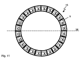
図11には、ただ1つのグループのバーナ9だけが停止されていて、残りのバーナ9は運転されている、シーケンシャル燃焼式のガスタービンの第2の燃焼器15の横断面図が示してある。この配置形態は、作動させられているバーナ9のCOエミッションに与えられる、停止されている低温の隣接バーナの影響が極めて大きく、この場合に生じる燃焼器15の好ましくない出口温度分布を後続の第2のタービン12によって許容することができるかまたは温度分布に冷却を適合させることができる場合に有利である。
FIG. 11 shows a cross-sectional view of the
上述した全ての利点は、記載した組合せに限定されているだけでなく、本発明の範囲を逸脱することなしに、別の組合せでも、単独でも使用可能である。たとえば、個々のバーナ9またはバーナ9のグループを停止するための任意に異なる形態が可能である。
All of the advantages described above are not limited to the combinations described, but can be used in other combinations or alone without departing from the scope of the present invention. For example, arbitrarily different forms for stopping
1 圧縮機
2 吸入空気
3 圧縮された空気
4 第1の燃焼器
5 燃料供給部材
6 高温ガス
7 第1のタービン
8 部分膨張させられた高温ガス
9 第2の燃焼器のバーナ
10 燃料供給部材
11 高温ガス
12 第2のタービン
13 (排熱回収ボイラへの)排ガス
14 調節可能な圧縮機案内羽根
15 第2の燃焼器
16 低圧側冷却空気調整弁
17 担持空気調整弁
18 軸
19 発電機
21 高圧側冷却空気調整弁
22 高圧側冷却空気
23 冷却空気
24 担持空気
25 凍結防止調整弁
26 凍結防止管路
27 個別調整弁
28 燃料調整弁
29 燃料供給部材
30 燃料環状管路
31 第2の分割グループに対する燃料環状管路
32 第1の分割グループに対する燃料環状管路
33 第1の分割グループに対する燃料調整弁
34 第2の分割グループに対する燃料調整弁
35 高圧側冷却空気冷却器
36 低圧側冷却空気冷却器
37 個別切換弁
38 分離平面
TAT タービン出口温度
TAT1 第1のタービンのタービン出口温度
TAT2 第2のタービンのタービン出口温度
TIT タービン入口温度
TIT1 第1のタービンのタービン入口温度
TIT2 第2のタービンのタービン入口温度
Prel 相対的な出力
X 作動させられているバーナ
O 停止されているバーナ
DESCRIPTION OF SYMBOLS 1
Claims (18)
Applications Claiming Priority (3)
| Application Number | Priority Date | Filing Date | Title |
|---|---|---|---|
| CH00536/09A CH700796A1 (en) | 2009-04-01 | 2009-04-01 | Method for CO-emission operation of a gas turbine with sequential combustion and gas turbine with improved part-load emission behavior. |
| CH00536/09 | 2009-04-01 | ||
| PCT/EP2010/053171 WO2010112318A1 (en) | 2009-04-01 | 2010-03-12 | Gas turbine exhibiting improved partial load emission behavior |
Publications (3)
| Publication Number | Publication Date |
|---|---|
| JP2012522922A JP2012522922A (en) | 2012-09-27 |
| JP2012522922A5 JP2012522922A5 (en) | 2013-05-02 |
| JP5680053B2 true JP5680053B2 (en) | 2015-03-04 |
Family
ID=40848719
Family Applications (1)
| Application Number | Title | Priority Date | Filing Date |
|---|---|---|---|
| JP2012502550A Expired - Fee Related JP5680053B2 (en) | 2009-04-01 | 2010-03-12 | Gas turbine with improved partial load emission characteristics |
Country Status (7)
| Country | Link |
|---|---|
| US (2) | US8434312B2 (en) |
| EP (1) | EP2414653B1 (en) |
| JP (1) | JP5680053B2 (en) |
| CH (1) | CH700796A1 (en) |
| ES (1) | ES2627679T3 (en) |
| RU (1) | RU2562681C2 (en) |
| WO (1) | WO2010112318A1 (en) |
Families Citing this family (39)
| Publication number | Priority date | Publication date | Assignee | Title |
|---|---|---|---|---|
| CH700796A1 (en) | 2009-04-01 | 2010-10-15 | Alstom Technology Ltd | Method for CO-emission operation of a gas turbine with sequential combustion and gas turbine with improved part-load emission behavior. |
| JP2013545916A (en) * | 2010-10-19 | 2013-12-26 | アルストム テクノロジー リミテッド | Method for operating a combined cycle power plant for cogeneration and a combined cycle power plant for implementing the method |
| ES2525168T3 (en) * | 2010-10-19 | 2014-12-18 | Alstom Technology Ltd | Operating method of a combined cycle power plant with cogeneration, and a combined cycle power plant to perform the method |
| CH704829A2 (en) * | 2011-04-08 | 2012-11-15 | Alstom Technology Ltd | Gas turbine group and associated operating method. |
| WO2014001230A1 (en) | 2012-06-29 | 2014-01-03 | Alstom Technology Ltd | Method for a part load co reduction operation for a sequential gas turbine |
| RU2561956C2 (en) | 2012-07-09 | 2015-09-10 | Альстом Текнолоджи Лтд | Gas-turbine combustion system |
| RU2563445C2 (en) * | 2012-07-13 | 2015-09-20 | Альстом Текнолоджи Лтд | Method and device to regulate surging of gas turbine engine |
| AU2013219140B2 (en) * | 2012-08-24 | 2015-10-08 | Ansaldo Energia Switzerland AG | Method for mixing a dilution air in a sequential combustion system of a gas turbine |
| CA2824124C (en) | 2012-08-24 | 2016-10-04 | Alstom Technology Ltd. | Method for mixing a dilution air in a sequential combustion system of a gas turbine |
| CA2829613C (en) | 2012-10-22 | 2016-02-23 | Alstom Technology Ltd. | Method for operating a gas turbine with sequential combustion and gas turbine for conducting said method |
| JP5899133B2 (en) * | 2013-02-01 | 2016-04-06 | 株式会社日立製作所 | 2-shaft gas turbine |
| EP2600063A3 (en) * | 2013-02-19 | 2014-05-07 | Alstom Technology Ltd | Method of operating a gas turbine with staged and/or sequential combustion |
| US9624829B2 (en) | 2013-03-05 | 2017-04-18 | Industrial Turbine Company (Uk) Limited | Cogen heat load matching through reheat and capacity match |
| US10036317B2 (en) * | 2013-03-05 | 2018-07-31 | Industrial Turbine Company (Uk) Limited | Capacity control of turbine by the use of a reheat combustor in multi shaft engine |
| EP2789915A1 (en) * | 2013-04-10 | 2014-10-15 | Alstom Technology Ltd | Method for operating a combustion chamber and combustion chamber |
| EP2829705A1 (en) * | 2013-07-24 | 2015-01-28 | Alstom Technology Ltd | Gas turbine and method of controlling gas turbine |
| EP2835516A1 (en) | 2013-08-08 | 2015-02-11 | Alstom Technology Ltd | Gas turbine with improved part load emissions behavior |
| JP6190670B2 (en) * | 2013-08-30 | 2017-08-30 | 三菱日立パワーシステムズ株式会社 | Gas turbine combustion system |
| EP2857658A1 (en) | 2013-10-01 | 2015-04-08 | Alstom Technology Ltd | Gas turbine with sequential combustion arrangement |
| RU2561754C1 (en) * | 2014-02-12 | 2015-09-10 | Открытое акционерное общество "Газпром" | Ring combustion chamber of gas-turbine engine and its operation method |
| US20160237904A1 (en) * | 2015-02-13 | 2016-08-18 | General Electric Company | Systems and methods for controlling an inlet air temperature of an intercooled gas turbine engine |
| EP3061944A1 (en) | 2015-02-26 | 2016-08-31 | General Electric Technology GmbH | Method for controlling the operation of a gas turbine with sequential combustion |
| US10316696B2 (en) | 2015-05-08 | 2019-06-11 | General Electric Company | System and method for improving exhaust energy recovery |
| US9957900B2 (en) | 2015-05-11 | 2018-05-01 | General Electric Company | System and method for flow control in turbine |
| US10330015B2 (en) * | 2015-09-25 | 2019-06-25 | General Electric Company | Transient emission temperature control of turbine systems |
| US10920676B2 (en) * | 2016-11-17 | 2021-02-16 | General Electric Company | Low partial load emission control for gas turbine system |
| HUE050483T2 (en) * | 2017-03-14 | 2020-12-28 | Gen Electric | Method and system for controlling a sequential gas turbine engine |
| US11092085B2 (en) * | 2017-03-14 | 2021-08-17 | General Electric Company | Method and system for controlling a sequential gas turbine engine |
| EP3421761B1 (en) * | 2017-06-30 | 2020-11-25 | Ansaldo Energia IP UK Limited | Second-stage combustor for a sequential combustor of a gas turbine |
| RU2685802C1 (en) * | 2017-12-28 | 2019-04-23 | Игорь Анатольевич Мнушкин | Gas pumping unit |
| EP3524799A1 (en) | 2018-02-13 | 2019-08-14 | Siemens Aktiengesellschaft | Method for operating a burner assembly of a gas turbine |
| EP3578762A1 (en) * | 2018-06-08 | 2019-12-11 | General Electric Technology GmbH | Method for determining an outlet temperature of an upstream combustion stage in a gas turbine engine having at least two serially arranged combustion stages |
| EP3683426B1 (en) * | 2019-01-15 | 2023-05-03 | Ansaldo Energia Switzerland AG | Method for operating a gas turbine power plant and gas turbine power plant |
| JP7231493B2 (en) * | 2019-06-12 | 2023-03-01 | 三菱重工業株式会社 | Control device, gas turbine, control method and program |
| EP3772616B1 (en) * | 2019-08-08 | 2024-02-07 | Ansaldo Energia Switzerland AG | Method for operating a gas turbine assembly comprising a sequential combustor |
| EP3822468B1 (en) * | 2019-11-18 | 2024-04-03 | Ansaldo Energia Switzerland AG | Gas turbine engine operable at very low partial load and method of controlling a gas turbine engine |
| US11203986B1 (en) * | 2020-06-08 | 2021-12-21 | General Electric Company | Systems and methods for extended emissions compliant operation of a gas turbine engine |
| CN112627989A (en) * | 2021-01-08 | 2021-04-09 | 大连欧谱纳透平动力科技有限公司 | System and method for controlling exhaust temperature and nitrogen oxide concentration of small gas turbine |
| EP4206452A1 (en) * | 2021-12-30 | 2023-07-05 | Ansaldo Energia Switzerland AG | Method for operating a gas turbine assembly for a power plant and gas turbine assembly for a power plant |
Family Cites Families (17)
| Publication number | Priority date | Publication date | Assignee | Title |
|---|---|---|---|---|
| US5226287A (en) | 1991-07-19 | 1993-07-13 | General Electric Company | Compressor stall recovery apparatus |
| JP3131805B2 (en) * | 1992-06-16 | 2001-02-05 | 三井造船株式会社 | Fuel distribution control device for gas turbine combustor |
| JPH06213456A (en) * | 1993-01-13 | 1994-08-02 | Mitsui Eng & Shipbuild Co Ltd | Combustion device for gas turbine and its fuel control device |
| EP0646704B1 (en) * | 1993-09-06 | 1997-11-26 | Asea Brown Boveri Ag | Method for controlling a gas turbine plan equipped with two combustion chambers |
| DE59309644D1 (en) * | 1993-09-06 | 1999-07-15 | Asea Brown Boveri | Process for creating a partial load operation for a gas turbine group |
| DE4446610A1 (en) * | 1994-12-24 | 1996-06-27 | Abb Management Ag | Process for operating a gas turbine group |
| RU2186232C2 (en) * | 1997-05-06 | 2002-07-27 | Особов Виктор Исаакович | Gas turbine plant operation method |
| EP0921292B1 (en) * | 1997-12-08 | 2003-09-10 | ALSTOM (Switzerland) Ltd | Method for controlling a gas turbine group |
| DE59811336D1 (en) * | 1998-07-22 | 2004-06-09 | Alstom Technology Ltd Baden | Method for operating a gas turbine combustion chamber with liquid fuel |
| JP2002295831A (en) * | 2001-03-30 | 2002-10-09 | Mitsubishi Heavy Ind Ltd | Combustion control system for gas turbine combustor |
| DE10160997A1 (en) * | 2001-12-12 | 2003-07-03 | Rolls Royce Deutschland | Lean premix burner for a gas turbine and method for operating a lean premix burner |
| EP1531305A1 (en) * | 2003-11-12 | 2005-05-18 | United Technologies Corporation | Multi-point fuel injector |
| JP4015656B2 (en) * | 2004-11-17 | 2007-11-28 | 三菱重工業株式会社 | Gas turbine combustor |
| JP4486549B2 (en) * | 2005-06-06 | 2010-06-23 | 三菱重工業株式会社 | Gas turbine combustor |
| US7565805B2 (en) | 2005-11-22 | 2009-07-28 | General Electric Company | Method for operating gas turbine engine systems |
| WO2010000020A1 (en) | 2008-06-30 | 2010-01-07 | Cathrx Ltd | A catheter |
| CH700796A1 (en) | 2009-04-01 | 2010-10-15 | Alstom Technology Ltd | Method for CO-emission operation of a gas turbine with sequential combustion and gas turbine with improved part-load emission behavior. |
-
2009
- 2009-04-01 CH CH00536/09A patent/CH700796A1/en not_active Application Discontinuation
-
2010
- 2010-03-12 JP JP2012502550A patent/JP5680053B2/en not_active Expired - Fee Related
- 2010-03-12 EP EP10709482.3A patent/EP2414653B1/en not_active Not-in-force
- 2010-03-12 WO PCT/EP2010/053171 patent/WO2010112318A1/en active Application Filing
- 2010-03-12 RU RU2011144106/06A patent/RU2562681C2/en not_active IP Right Cessation
- 2010-03-12 ES ES10709482.3T patent/ES2627679T3/en active Active
-
2011
- 2011-09-23 US US13/241,983 patent/US8434312B2/en not_active Expired - Fee Related
-
2013
- 2013-04-03 US US13/855,857 patent/US8794008B2/en not_active Expired - Fee Related
Also Published As
| Publication number | Publication date |
|---|---|
| RU2011144106A (en) | 2013-05-10 |
| US20130219904A1 (en) | 2013-08-29 |
| US8794008B2 (en) | 2014-08-05 |
| JP2012522922A (en) | 2012-09-27 |
| WO2010112318A1 (en) | 2010-10-07 |
| EP2414653B1 (en) | 2017-03-01 |
| ES2627679T3 (en) | 2017-07-31 |
| CH700796A1 (en) | 2010-10-15 |
| EP2414653A1 (en) | 2012-02-08 |
| RU2562681C2 (en) | 2015-09-10 |
| US20120017601A1 (en) | 2012-01-26 |
| US8434312B2 (en) | 2013-05-07 |
Similar Documents
| Publication | Publication Date | Title |
|---|---|---|
| JP5680053B2 (en) | Gas turbine with improved partial load emission characteristics | |
| US9624830B2 (en) | Gas turbine with improved part load emissions behavior | |
| CN104981663B (en) | Method for operating a gas turbine with staged and/or sequential combustion | |
| EP2846022B1 (en) | Gas turbine combustion system | |
| JP6253066B2 (en) | Method of partial load CO reduction operation and gas turbine for a two-stage combustion gas turbine | |
| US8015826B2 (en) | Engine brake for part load CO reduction | |
| US9470145B2 (en) | System and method for heating fuel in a combined cycle gas turbine | |
| US7124591B2 (en) | Method for operating a gas turbine | |
| US9435258B2 (en) | System and method for heating combustor fuel | |
| US20170058784A1 (en) | System and method for maintaining emissions compliance while operating a gas turbine at turndown condition | |
| CA2865729A1 (en) | Gas turbine with sequential combustion arrangement | |
| US20170058771A1 (en) | System and method for generating steam during gas turbine low-load conditions | |
| EP2577025B1 (en) | Method for increasing an emissions compliant load range for a combined-cycle system | |
| EP3822468B1 (en) | Gas turbine engine operable at very low partial load and method of controlling a gas turbine engine | |
| Jakoby et al. | Turn-Down Capability of Ansaldo Energia’s GT26 |
Legal Events
| Date | Code | Title | Description |
|---|---|---|---|
| A521 | Request for written amendment filed |
Free format text: JAPANESE INTERMEDIATE CODE: A523 Effective date: 20130311 |
|
| A621 | Written request for application examination |
Free format text: JAPANESE INTERMEDIATE CODE: A621 Effective date: 20130311 |
|
| A977 | Report on retrieval |
Free format text: JAPANESE INTERMEDIATE CODE: A971007 Effective date: 20131212 |
|
| A131 | Notification of reasons for refusal |
Free format text: JAPANESE INTERMEDIATE CODE: A131 Effective date: 20131216 |
|
| A601 | Written request for extension of time |
Free format text: JAPANESE INTERMEDIATE CODE: A601 Effective date: 20140317 |
|
| A602 | Written permission of extension of time |
Free format text: JAPANESE INTERMEDIATE CODE: A602 Effective date: 20140325 |
|
| A601 | Written request for extension of time |
Free format text: JAPANESE INTERMEDIATE CODE: A601 Effective date: 20140416 |
|
| A602 | Written permission of extension of time |
Free format text: JAPANESE INTERMEDIATE CODE: A602 Effective date: 20140423 |
|
| A601 | Written request for extension of time |
Free format text: JAPANESE INTERMEDIATE CODE: A601 Effective date: 20140516 |
|
| A602 | Written permission of extension of time |
Free format text: JAPANESE INTERMEDIATE CODE: A602 Effective date: 20140523 |
|
| A521 | Request for written amendment filed |
Free format text: JAPANESE INTERMEDIATE CODE: A523 Effective date: 20140526 |
|
| TRDD | Decision of grant or rejection written | ||
| A01 | Written decision to grant a patent or to grant a registration (utility model) |
Free format text: JAPANESE INTERMEDIATE CODE: A01 Effective date: 20141208 |
|
| A61 | First payment of annual fees (during grant procedure) |
Free format text: JAPANESE INTERMEDIATE CODE: A61 Effective date: 20150106 |
|
| R150 | Certificate of patent or registration of utility model |
Ref document number: 5680053 Country of ref document: JP Free format text: JAPANESE INTERMEDIATE CODE: R150 |
|
| S533 | Written request for registration of change of name |
Free format text: JAPANESE INTERMEDIATE CODE: R313533 |
|
| R350 | Written notification of registration of transfer |
Free format text: JAPANESE INTERMEDIATE CODE: R350 |
|
| S111 | Request for change of ownership or part of ownership |
Free format text: JAPANESE INTERMEDIATE CODE: R313113 |
|
| R350 | Written notification of registration of transfer |
Free format text: JAPANESE INTERMEDIATE CODE: R350 |
|
| LAPS | Cancellation because of no payment of annual fees |