CN104981663B - Method of operating a gas turbine with staged and/or continuous combustion - Google Patents
Method of operating a gas turbine with staged and/or continuous combustion Download PDFInfo
- Publication number
- CN104981663B CN104981663B CN201480009475.5A CN201480009475A CN104981663B CN 104981663 B CN104981663 B CN 104981663B CN 201480009475 A CN201480009475 A CN 201480009475A CN 104981663 B CN104981663 B CN 104981663B
- Authority
- CN
- China
- Prior art keywords
- burner
- turbine
- temperature
- load
- fuel
- Prior art date
- Legal status (The legal status is an assumption and is not a legal conclusion. Google has not performed a legal analysis and makes no representation as to the accuracy of the status listed.)
- Active
Links
Images
Classifications
-
- F—MECHANICAL ENGINEERING; LIGHTING; HEATING; WEAPONS; BLASTING
- F23—COMBUSTION APPARATUS; COMBUSTION PROCESSES
- F23R—GENERATING COMBUSTION PRODUCTS OF HIGH PRESSURE OR HIGH VELOCITY, e.g. GAS-TURBINE COMBUSTION CHAMBERS
- F23R3/00—Continuous combustion chambers using liquid or gaseous fuel
- F23R3/28—Continuous combustion chambers using liquid or gaseous fuel characterised by the fuel supply
- F23R3/34—Feeding into different combustion zones
- F23R3/346—Feeding into different combustion zones for staged combustion
-
- F—MECHANICAL ENGINEERING; LIGHTING; HEATING; WEAPONS; BLASTING
- F02—COMBUSTION ENGINES; HOT-GAS OR COMBUSTION-PRODUCT ENGINE PLANTS
- F02C—GAS-TURBINE PLANTS; AIR INTAKES FOR JET-PROPULSION PLANTS; CONTROLLING FUEL SUPPLY IN AIR-BREATHING JET-PROPULSION PLANTS
- F02C9/00—Controlling gas-turbine plants; Controlling fuel supply in air- breathing jet-propulsion plants
- F02C9/16—Control of working fluid flow
-
- F—MECHANICAL ENGINEERING; LIGHTING; HEATING; WEAPONS; BLASTING
- F02—COMBUSTION ENGINES; HOT-GAS OR COMBUSTION-PRODUCT ENGINE PLANTS
- F02C—GAS-TURBINE PLANTS; AIR INTAKES FOR JET-PROPULSION PLANTS; CONTROLLING FUEL SUPPLY IN AIR-BREATHING JET-PROPULSION PLANTS
- F02C6/00—Plural gas-turbine plants; Combinations of gas-turbine plants with other apparatus; Adaptations of gas-turbine plants for special use
- F02C6/003—Gas-turbine plants with heaters between turbine stages
-
- F—MECHANICAL ENGINEERING; LIGHTING; HEATING; WEAPONS; BLASTING
- F02—COMBUSTION ENGINES; HOT-GAS OR COMBUSTION-PRODUCT ENGINE PLANTS
- F02C—GAS-TURBINE PLANTS; AIR INTAKES FOR JET-PROPULSION PLANTS; CONTROLLING FUEL SUPPLY IN AIR-BREATHING JET-PROPULSION PLANTS
- F02C9/00—Controlling gas-turbine plants; Controlling fuel supply in air- breathing jet-propulsion plants
- F02C9/16—Control of working fluid flow
- F02C9/20—Control of working fluid flow by throttling; by adjusting vanes
- F02C9/22—Control of working fluid flow by throttling; by adjusting vanes by adjusting turbine vanes
-
- F—MECHANICAL ENGINEERING; LIGHTING; HEATING; WEAPONS; BLASTING
- F02—COMBUSTION ENGINES; HOT-GAS OR COMBUSTION-PRODUCT ENGINE PLANTS
- F02C—GAS-TURBINE PLANTS; AIR INTAKES FOR JET-PROPULSION PLANTS; CONTROLLING FUEL SUPPLY IN AIR-BREATHING JET-PROPULSION PLANTS
- F02C9/00—Controlling gas-turbine plants; Controlling fuel supply in air- breathing jet-propulsion plants
- F02C9/48—Control of fuel supply conjointly with another control of the plant
-
- F—MECHANICAL ENGINEERING; LIGHTING; HEATING; WEAPONS; BLASTING
- F23—COMBUSTION APPARATUS; COMBUSTION PROCESSES
- F23R—GENERATING COMBUSTION PRODUCTS OF HIGH PRESSURE OR HIGH VELOCITY, e.g. GAS-TURBINE COMBUSTION CHAMBERS
- F23R3/00—Continuous combustion chambers using liquid or gaseous fuel
- F23R3/28—Continuous combustion chambers using liquid or gaseous fuel characterised by the fuel supply
- F23R3/36—Supply of different fuels
-
- F—MECHANICAL ENGINEERING; LIGHTING; HEATING; WEAPONS; BLASTING
- F05—INDEXING SCHEMES RELATING TO ENGINES OR PUMPS IN VARIOUS SUBCLASSES OF CLASSES F01-F04
- F05D—INDEXING SCHEME FOR ASPECTS RELATING TO NON-POSITIVE-DISPLACEMENT MACHINES OR ENGINES, GAS-TURBINES OR JET-PROPULSION PLANTS
- F05D2270/00—Control
- F05D2270/01—Purpose of the control system
- F05D2270/05—Purpose of the control system to affect the output of the engine
- F05D2270/053—Explicitly mentioned power
-
- F—MECHANICAL ENGINEERING; LIGHTING; HEATING; WEAPONS; BLASTING
- F23—COMBUSTION APPARATUS; COMBUSTION PROCESSES
- F23R—GENERATING COMBUSTION PRODUCTS OF HIGH PRESSURE OR HIGH VELOCITY, e.g. GAS-TURBINE COMBUSTION CHAMBERS
- F23R2900/00—Special features of, or arrangements for continuous combustion chambers; Combustion processes therefor
- F23R2900/03341—Sequential combustion chambers or burners
Landscapes
- Engineering & Computer Science (AREA)
- Chemical & Material Sciences (AREA)
- Combustion & Propulsion (AREA)
- Mechanical Engineering (AREA)
- General Engineering & Computer Science (AREA)
- Physics & Mathematics (AREA)
- Fluid Mechanics (AREA)
- Control Of Turbines (AREA)
- Engine Equipment That Uses Special Cycles (AREA)
Abstract
Description
技术领域technical field
本发明涉及一种用于操作具有分级和/或连续燃烧的燃气涡轮的方法。此外,本发明涉及一种用于实施用于操作具有分级和/或连续燃烧的燃气涡轮的方法的燃气涡轮。The present invention relates to a method for operating a gas turbine with staged and/or continuous combustion. Furthermore, the invention relates to a gas turbine for implementing a method for operating a gas turbine with staged and/or continuous combustion.
背景技术Background technique
由于由非稳定可再生源(例如,风、太阳能)的发电增加,故现有的基于GT的发电站日益用于平衡电力需求和电网稳定性,因此需要改进的操作灵活性。这隐含了GT发电站通常在低于基本负载设计点的负载下操作,即,在较低燃烧器入口和燃烧温度下。在某些极限下,这降低了火焰稳定性和烧尽,同时增加了CO排放产生。As power generation from unstable renewable sources (eg, wind, solar) increases, existing GT-based power plants are increasingly used to balance power demand and grid stability, thus requiring improved operational flexibility. This implies that GT power plants typically operate at loads below the base load design point, ie, at lower combustor inlet and firing temperatures. At certain limits, this reduces flame stability and burnout, while increasing CO emissions production.
同时,排气极限值和总体排放许可变得更紧,以致于需要:At the same time, exhaust limits and overall emission permits have become tighter, so that:
在较低排放值下操作;operate at lower emission values;
在部分负载操作下且在瞬变操作期间也保持低排放,因为这些也算作累积的排放极限。Emissions are also kept low at part load operation and during transient operation as these also count as cumulative emission limits.
根据现有技术水平的燃烧系统设计成应对操作条件下的某些可变性,例如,通过调整压缩机入口质量或控制不同焚烧器、燃料级或燃烧器间的燃料分流。关于该方面的目的在关于分级或连续燃烧构想的燃气涡轮中给出,当在不同燃烧温度下操作第一和第二级或燃烧器的可能性已经允许较宽负载范围内的操作的优化时。Combustion systems according to the state of the art are designed to cope with certain variability in operating conditions, eg by adjusting compressor inlet mass or controlling fuel split between different burners, fuel stages or burners. Objects in this regard are given in gas turbines conceived in relation to staged or continuous combustion, when the possibility of operating the first and second stages or combustors at different combustion temperatures already allows optimization of operation over a wider load range .
从EP0646704A1出现了一种用于控制燃气涡轮发电站的方法,该燃气涡轮发电站基本上包括压缩机单元(1)、高压燃烧室(4)、高压涡轮(6)、低压燃烧室(9)、低压涡轮(12)和发电机(14),用于高压燃烧室(4)的燃料(FH)量通过由低压涡轮(12)的出口处的温度(T13)的值减去该处可检测的相应温升(DELTA T)构成的校正温度信号调整。该温度信号(T13-DELTA T)通过从低压涡轮(12)的出口处测得的温度减去引入到低压燃烧室(9)中的燃料(FL)量产生的温升(DELTA T)来记录。对于低压燃烧室(9)的燃料(FL)量,使用低压涡轮(12)的出口处的未校正的温度信号。From EP0646704A1 emerges a method for controlling a gas turbine power plant which basically comprises a compressor unit (1), a high pressure combustion chamber (4), a high pressure turbine (6), a low pressure combustion chamber (9) , low pressure turbine (12) and generator (14), the amount of fuel (FH) for the high pressure combustion chamber (4) is detectable by subtracting the value of the temperature (T13) at the outlet of the low pressure turbine (12) there The corresponding temperature rise (DELTA T) constitutes the correction temperature signal adjustment. The temperature signal (T13-DELTA T) is recorded by subtracting the temperature rise (DELTA T) resulting from the amount of fuel (FL) introduced into the low pressure combustion chamber (9) from the temperature measured at the outlet of the low pressure turbine (12) . For the fuel (FL) quantity of the low pressure combustion chamber (9), the uncorrected temperature signal at the outlet of the low pressure turbine (12) is used.
根据EP0646705A1的本发明提出了一种用于在涡轮发电站中提供部分负载操作的方法。该燃气涡轮发电站基本上包括压缩机单元(1)、布置在压缩机单元(1)下游的HP燃烧室(4)、布置在该HP燃烧室(4)下游的HP涡轮(5)、布置在该HP涡轮(5)下游的LP燃烧室(8),通过自燃操作,并且其热气体作用于LP涡轮(11)上。将LP燃烧室(8)中的燃料量减少至零将HP涡轮(5)的出口处的温度保持基本上恒定。在降低LP燃烧室(8)中的燃料量期间,用于HP燃烧室(4)的燃料量还保持大致恒定,并且HP涡轮(5)的入口处的温度因此同样保持恒定。The invention according to EP0646705A1 proposes a method for providing part load operation in a turbine power plant. The gas turbine power plant basically comprises a compressor unit (1), an HP combustion chamber (4) arranged downstream of the compressor unit (1), an HP turbine (5) arranged downstream of the HP combustion chamber (4), arranged The LP combustion chamber (8), downstream of this HP turbine (5), operates by auto-ignition and its hot gases act on the LP turbine (11). Reducing the amount of fuel in the LP combustion chamber (8) to zero keeps the temperature at the outlet of the HP turbine (5) substantially constant. During the reduction of the fuel quantity in the LP combustion chamber (8), the fuel quantity for the HP combustion chamber (4) also remains approximately constant, and the temperature at the inlet of the HP turbine (5) therefore also remains constant.
关于EP0718470A2的燃气涡轮包括压缩机(1)、具有对应的高压涡轮(6)和低压涡轮(10)的第一燃烧室(4)和第二燃烧室(8),以及至少一个发电机(13)。燃气涡轮的部分负载操作通过调整压缩机导叶来达到标称负载的百分之50以下的负载而实现。在调整期间,高压涡轮入口温度保持恒定,而低压涡轮入口温度连续下降。低压涡轮出口温度保持恒定。对于低于使用导叶调整实现的那些的负载,首先是低压接着是高压涡轮入口温度降低。The gas turbine with respect to EP0718470A2 comprises a compressor (1), a first combustion chamber (4) and a second combustion chamber (8) with corresponding high pressure turbine (6) and low pressure turbine (10), and at least one generator (13) ). Part load operation of the gas turbine is achieved by adjusting the compressor vanes to achieve a load below 50 percent of the nominal load. During the tuning period, the high pressure turbine inlet temperature remains constant, while the low pressure turbine inlet temperature continuously decreases. The low pressure turbine outlet temperature remains constant. For loads lower than those achieved using guide vane adjustment, first low pressure followed by high pressure turbine inlet temperature reduction.
从EP0921292A1出现了一种用于调节以连续燃烧操作的燃气涡轮发电机组的方法,其中操作第一燃烧室所必需的燃料量首先随压缩机的出口处主要的压力变化而控制。该燃料量与该压力之间的比借助于再现第一涡轮的入口处的温度与该温度的期望值的偏差的因数连续地更新。操作第二燃烧室所必需的燃料量随第二涡轮入口处主要的压力变化而控制,并且该燃料量与该压力之间的比同样借助于再现第二涡轮的入口温度与该温度的期望值的偏差的因数连续地更新。系统中的惯性借助于该压力支持调节来中和。From EP0921292A1 emerges a method for regulating a gas turbine generator set operating with continuous combustion, wherein the amount of fuel necessary to operate the first combustion chamber is first controlled with the prevailing pressure changes at the outlet of the compressor. The ratio between the fuel quantity and the pressure is continuously updated by means of a factor that reproduces the deviation of the temperature at the inlet of the first turbine from the expected value of this temperature. The amount of fuel necessary to operate the second combustion chamber is controlled as a function of the prevailing pressure change at the inlet of the second turbine, and the ratio between the amount of fuel and this pressure is likewise by means of reproducing the inlet temperature of the second turbine and the desired value for this temperature. The bias factor is updated continuously. Inertia in the system is neutralized by means of this pressure support adjustment.
此外,为了保护环境起见,燃气涡轮发动机的CO排放需要减少。此类排放已知在燃烧室中没有足够的时间确保CO到CO2的氧化和/或该氧化由于与燃烧器中的冷区接触而局部骤冷时发生。由于燃烧器入口和/或燃烧温度在部分负载状态下较小,故CO到CO2的氧化变更慢,因此CO排放通常在这些状态下趋于增加。Furthermore, in order to protect the environment, CO emissions from gas turbine engines need to be reduced. Such emissions are known to occur when there is insufficient time in the combustor to ensure oxidation of CO to CO 2 and/or this oxidation is locally quenched due to contact with a cold zone in the combustor. Since the combustor inlet and/or combustion temperature is lower at part load conditions, the oxidation of CO to CO2 is slower, so CO emissions generally tend to increase at these conditions.
CO排放的减少继而可通过在燃气涡轮的停机点处减小燃气涡轮负载来利用。这由于减少的CO2(并且在一些情况中是其它污染物)排放而减小了环境影响,并且由于发动机停机期间的较少燃料消耗而降低了电力的总成本。最后,由于节省了CO催化剂,故CO排放减少可投入降低第一成本。在该情况下,可避免CO催化剂(或至少减少)。同时,由于催化剂而出现的损失将消除(或至少减少),并且因此发电站的总体效率提高。The reduction in CO emissions can then be exploited by reducing gas turbine load at gas turbine shutdown points. This reduces the environmental impact due to reduced CO2 (and in some cases other pollutants) emissions, and reduces the overall cost of electricity due to less fuel consumption during engine shutdown. Finally, the reduction in CO emissions can be invested in lowering the first cost due to the savings in CO catalyst. In this case, CO catalysts can be avoided (or at least reduced). At the same time, losses due to the catalyst will be eliminated (or at least reduced) and thus the overall efficiency of the power plant will increase.
根据US2012/0017601A1,该现有技术水平的基础为用于操作燃气涡轮的方法,其保持了操作第二燃烧器的焚烧器的空气比λ低于部分负载操作期间的最大空气比λmax。该方法基本上特征为三个新元素,并且还为可独立地或组合地实施的补充措施。According to US 2012/0017601 A1, this state of the art is based on a method for operating a gas turbine which keeps the air ratio λ of the incinerator operating the second combustor below the maximum air ratio λmax during part load operation. The method essentially features three new elements, and is also complementary measures that can be implemented independently or in combination.
该情况中的最大空气比λmax取决于在焚烧器和燃烧器的设计时将观察到的CO排放极限,以及还取决于操作条件,即是说,尤其是焚烧器入口温度。The maximum air ratio λmax in this case depends on the CO emission limits to be observed in the design of the incinerator and the burner, and also on the operating conditions, that is to say in particular the incinerator inlet temperature.
第一元素为成排的可变压缩机入口导叶的操作原理的变化,这允许第二燃烧器仅在较高部分负载下进入操作。从空载操作开始,成排的可变压缩机入口导叶已经打开,同时仅第一燃烧器操作。这允许在第二燃烧器必须进入操作之前负载升高至较高相对负载。如果成排的可变压缩机入口导叶打开并且高压涡轮的热气体温度或涡轮入口温度达到极限,则第二燃烧器供应有燃料。The first element is a change in the operating principle of the row of variable compressor inlet guide vanes, which allows the second combustor to come into operation only at higher part loads. Beginning with no-load operation, rows of variable compressor inlet guide vanes have been opened while only the first combustor is operating. This allows the load to rise to a higher relative load before the second burner has to go into operation. The second combustor is supplied with fuel if the row of variable compressor inlet guide vanes are open and the hot gas temperature or turbine inlet temperature of the high pressure turbine reaches a limit.
此外,成排的可变压缩机入口导叶快速闭合。在高压涡轮的恒定涡轮入口温度TIT下闭合成排的可变压缩机入口导叶而没有对策将导致相对功率的显著减小。In addition, the rows of variable compressor inlet guide vanes close quickly. Closing the row of variable compressor inlet guide vanes at constant turbine inlet temperature TIT of the high pressure turbine without countermeasures will result in a significant reduction in relative power.
为了避免该功率减小,引入到第二燃烧器中的燃烧质量流可增加。第二燃烧器进入操作所处的最低负载和进入第二燃烧器中的最少燃料流因此显著地增加。To avoid this power reduction, the mass flow of combustion introduced into the second combustor can be increased. The second combustor enters the lowest load at which it operates and the minimum fuel flow into the second combustor is therefore significantly increased.
结果,第二燃烧器的最低热气体温度也增加,这减小了空气比λ,并且因此减少了CO排放。用于减小空气比λ的第二元素为通过在部分负载操作期间升高高压涡轮的涡轮排气温度TAT1和/或低压涡轮的涡轮排气温度TAT2的操作原理的变化。该升高允许了打开成排的可变压缩机入口导叶来转移至较高的负载点。As a result, the minimum hot gas temperature of the second burner also increases, which reduces the air ratio λ, and therefore CO emissions. The second element for reducing the air ratio λ is a change in the operating principle by raising the turbine exhaust temperature TAT1 of the high pressure turbine and/or the turbine exhaust temperature TAT2 of the low pressure turbine during part load operation. This elevation allows the rows of variable compressor inlet guide vanes to be opened to shift to higher load points.
常规地,第二涡轮的最高涡轮排气温度针对满载情况确定,并且燃气涡轮和可能的下游废热锅炉根据该温度来设计。这导致了第二涡轮的最高热气体温度在部分负载操作期间不由TIT2(第二涡轮的涡轮入口温度)限制,其中成排的可变压缩机入口导叶闭合,而由TAT2(第二涡轮的涡轮排气温度)限制。由于在具有至少一排可变压缩机入口导叶闭合的部分负载下,质量流和因此横跨涡轮的压力比减小,故涡轮入口温度与涡轮排气温度之比也减小。Conventionally, the maximum turbine exhaust temperature of the second turbine is determined for full load conditions, and the gas turbine and possibly downstream waste heat boilers are designed according to this temperature. This results in that the maximum hot gas temperature of the second turbine is not limited by TIT2 (turbine inlet temperature of the second turbine) during part load operation, where the row of variable compressor inlet guide vanes are closed, and is limited by TAT2 (the turbine inlet temperature of the second turbine) turbine exhaust temperature) limit. Since at part load with at least one row of variable compressor inlet guide vanes closed, the mass flow and thus the pressure ratio across the turbine is reduced, so the ratio of turbine inlet temperature to turbine exhaust gas temperature is also reduced.
发明内容SUMMARY OF THE INVENTION
由于出于机械完整性原因的可能的燃烧温度升高的限制,故现有的构想可不足以在整个部分负载范围期间将CO排放控制至给定值。Due to limitations of possible combustion temperature rises for mechanical integrity reasons, existing concepts may not be sufficient to control CO emissions to a given value during the entire part load range.
上述限制利用本发明通过同时控制第二级或第二燃烧器中的操作的焚烧器的数量和燃烧器入口导叶的位置来解决,从而允许了单个焚烧器在足够低的空气与燃料比下操作,而不需要升高涡轮操作温度。The above limitations are addressed with the present invention by simultaneously controlling the number of burners operating in the second stage or second burner and the position of the burner inlet guide vanes, thereby allowing a single burner to operate at a sufficiently low air to fuel ratio operation without the need to increase the turbine operating temperature.
因此,由本发明解决的主要技术问题在于在低负载下相对于连续发动机的CO排放、稳定燃烧和燃烧效率的改进的燃气涡轮燃烧性能,允许了提高的操作灵活性。Therefore, the main technical problem solved by the present invention is the improved gas turbine combustion performance at low load relative to continuous engine CO emissions, stable combustion and combustion efficiency, allowing for increased operational flexibility.
在卸载燃气涡轮,像例如,申请人的称为GT24/GT26的连续燃烧燃气涡轮期间,并且例如根据EP0620362A1,其中该文献形成本说明书的组成部分,第二级焚烧器独立地或组合地连续地切断,使得焚烧器在与在较高发动机负载下的相同热气体温度下保持操作,并且从而保持相同低CO排放。根据提出的方法,TAT_strike(最大局部涡轮出口温度)保持不变,这导致降低的TAT2(第二涡轮的平均涡轮出口温度),因为涡轮出口温度在切断的焚烧器下游局部地降低。During the unloading of a gas turbine, like for example the applicant's continuous combustion gas turbine called GT24/GT26, and for example according to EP0620362A1, which document forms an integral part of this specification, the second stage burners independently or in combination are continuously Switching off allows the incinerator to remain operating at the same hot gas temperature as at higher engine loads, and thus keep the same low CO emissions. According to the proposed method, TAT_strike (maximum local turbine outlet temperature) remains constant, which results in a reduced TAT2 (average turbine outlet temperature of the second turbine), as the turbine outlet temperature is locally reduced downstream of the shut-off burner.
为了保持操作中的焚烧器下游的足够热气体温度,调整压缩机的VIGV(可变入口导叶)。对于卸载,一个或多个焚烧器切断,并且VIGV可同时打开,以便保持相同的功率输出。对于加载,一个或多个焚烧器开启,并且VIGV可同时闭合,以便保持相同功率输出。在焚烧器对于略微减小的负载设定点必须切断的情况中,由于局部热气体温度限制,故燃料质量流将控制为较低,并且负载将因此下降。这通过打开VIGV来将负载调整至命令的设定点来补偿。通过打开VIGV,进入质量流增加,因此允许至有效焚烧器的燃料质量流的增大。此外,第二涡轮上的压力比增大,从而增大用于不变的TAT_strike的剩余操作的焚烧器的热气体温度(负载以相反顺序类似地执行)。In order to maintain sufficient hot gas temperature downstream of the incinerator in operation, the VIGV (variable inlet guide vane) of the compressor is adjusted. For unloading, one or more of the incinerators are switched off and the VIGVs can be switched on at the same time in order to maintain the same power output. For loading, one or more of the incinerators are open, and the VIGV can be closed at the same time in order to maintain the same power output. In the case where the burner has to shut off for a slightly reduced load set point, due to local hot gas temperature limitations, the fuel mass flow will be controlled lower and the load will drop accordingly. This is compensated by turning on the VIGV to adjust the load to the commanded set point. By opening the VIGV, the incoming mass flow increases, thus allowing an increase in fuel mass flow to the active burner. In addition, the pressure ratio on the second turbine increases, thereby increasing the hot gas temperature of the incinerator for the remainder of the operation of the constant TAT_strike (loads are performed similarly in reverse order).
基于这些发现,构想可应用于发动机,其在环形和/或筒形构架中的连续燃烧(具有或不具有高压涡轮)下运行。Based on these findings, concepts can be applied to engines that operate with continuous combustion (with or without high pressure turbines) in annular and/or canister architectures.
关于连续燃烧,燃烧器的组合可设置如下:For continuous combustion, the combination of burners can be set as follows:
至少一个燃烧器构造为筒形构架,具有至少一个操作涡轮。At least one combustor is configured as a can frame with at least one operating turbine.
第一燃烧器和第二燃烧器两者构造为连续的筒-筒构架,具有至少一个操作涡轮。Both the first combustor and the second combustor are constructed as a continuous can-can framework with at least one operating turbine.
第一燃烧器构造为环形燃烧室,并且第二燃烧器建造为筒形构造,具有至少一个操作涡轮。The first combustor is constructed as an annular combustion chamber and the second combustor is constructed in a can-shaped configuration with at least one operating turbine.
第一燃烧器构造为筒形构架,并且第二燃烧器构造为环形燃烧室,具有至少一个操作涡轮。The first combustor is configured as a can frame and the second combustor is configured as an annular combustion chamber with at least one operating turbine.
第一燃烧器和第二燃烧器两者构造为环形燃烧室,具有至少一个操作涡轮。Both the first combustor and the second combustor are configured as annular combustion chambers with at least one operating turbine.
第一燃烧器和第二燃烧器两者构造为环形燃烧室,具有中间操作涡轮。Both the first and second combustors are configured as annular combustion chambers with intermediate operating turbines.
除该方法之外,用于实施该方法的燃气涡轮为本发明的主题。取决于选择的方法或方法的组合,燃气涡轮的设计必须改变,并且/或者燃料分配系统和空气系统必须改变,以便确保方法的可行性。In addition to the method, the gas turbine used to implement the method is the subject of the present invention. Depending on the method or combination of methods chosen, the design of the gas turbine must be changed and/or the fuel distribution system and air system must be changed in order to ensure the viability of the method.
尤其还有制造公差在操作期间导致不同的压力损失和流速。公差选择成使得它们在正常操作期间实际上对操作性能没有影响,尤其是在高局部负载和满载下。然而,在具有高空气比λ的局部负载下,燃烧器可在其中甚至小扰动可对CO排放有显著影响的情况下操作。In particular there are also manufacturing tolerances that lead to different pressure losses and flow rates during operation. Tolerances are chosen such that they have virtually no effect on operational performance during normal operation, especially at high partial loads and full loads. However, at partial loads with a high air ratio λ, the combustor can operate in situations where even small disturbances can have a significant effect on CO emissions.
该过程可根据不同实施例来执行。第一实施例使用平均的测量排气温度TAT2。This process may be performed according to different embodiments. The first embodiment uses the average measured exhaust gas temperature TAT2.
1. 关于控制TAT2的瞬变状态中的过程(低压涡轮的平均测量排气温度):1. Regarding the process in the transient state of the control TAT2 (average measured exhaust gas temperature of the low pressure turbine):
1.1 燃气涡轮卸载,直到达到CO极限。1.1 The gas turbine is unloaded until the CO limit is reached.
1.2 第二燃烧器或第二级的独立焚烧器切断以减小负载。切断焚烧器导致燃料流重新分配至操作中的其余焚烧器,因此升高了局部热气体温度。此外,最高TAT2读数与算术平均值之间的差异增大。利用恒定的燃料流,负载将保持大致恒定。1.2 The second burner or the independent burner of the second stage is cut off to reduce the load. Switching off the incinerator results in a redistribution of the fuel flow to the remaining incinerators in operation, thus increasing the local hot gas temperature. In addition, the difference between the highest TAT2 reading and the arithmetic mean increased. With a constant fuel flow, the load will remain approximately constant.
1.3 利用平均TAT2限制的计划或TAT2限制的控制,使用测得的TAT_strike或从测得的TAT_strike到最大可允许TAT_strike的裕度,焚烧器操作之后的局部热气体温度控制至目标温度。例如,TAT2限制计划可基于相对负载或操作中的焚烧器的数量。由于TAT2限制的变化,故燃料质量流减小,并且因此功率降低。1.3 The local hot gas temperature after incinerator operation is controlled to the target temperature using the plan of the average TAT2 limit or the control of the TAT2 limit, using the measured TAT_strike or a margin from the measured TAT_strike to the maximum allowable TAT_strike. For example, the TAT2 limit plan may be based on relative load or the number of incinerators in operation. Due to the change in TAT2 limit, fuel mass flow is reduced, and therefore power is reduced.
1.4 为了达到目标负载,实际负载最终利用入口导叶调整,并且导致如先前部分中所述的预计CO排放减少。当开启入口导叶时,TAT2降低。燃料流可再次增加来增大至目标负载的功率。1.4 In order to reach the target load, the actual load is finally adjusted with the inlet guide vanes and results in a reduction in projected CO emissions as described in the previous section. When opening the inlet guide vanes, TAT2 decreases. Fuel flow can be increased again to increase power to the target load.
利用两个参数,TAT2限制计划或TAT2限制控制和切换的焚烧器的数量,CO排放和热气体温度限制可针对每个负载点调整。Using two parameters, the TAT2 limit schedule or the number of incinerators controlled and switched by TAT2 limit, CO emissions and hot gas temperature limits can be adjusted for each load point.
第二实施例使用平均的测得的最大局部排气温度(TAT_strike)。The second embodiment uses the average measured maximum local exhaust gas temperature (TAT_strike).
2. 具有最大局部排气温度控制的过程:2. Process with maximum local exhaust temperature control:
2.1 在燃气涡轮的低负载下,达到CO极限。2.1 At low loads of the gas turbine, the CO limit is reached.
2.2 第二燃烧器或燃烧级的焚烧器切断,以通过将之前喷射到切断的焚烧器的燃料重新分配至其余有效焚烧器来减少CO,从而恢复局部热气体温度。2.2 Burner cut-off of the second burner or combustion stage to reduce CO by redistributing fuel previously injected to the cut-off burner to the remaining active burners to restore local hot gas temperature.
2.3 如果TAT2_strike(第二涡轮的局部测得最大排气温度)增大超过最大可允许值,则控制器通过降低平均TAT2设定点来减少燃料质量流。由于降低的燃料质量流,故功率降低。2.3 If TAT2_strike (the locally measured maximum exhaust temperature of the second turbine) increases beyond the maximum allowable value, the controller reduces fuel mass flow by reducing the average TAT2 set point. Power is reduced due to the reduced fuel mass flow.
2.4 目标负载最终利用入口导叶来调整,并且导致如先前部分中所述的预计CO排放减少。当操作入口导叶时,TAT2降低。燃料流可再次增加来增大功率。2.4 The target load is finally adjusted using the inlet guide vanes and results in the projected CO emissions reduction as described in the previous section. When operating the inlet guide vanes, TAT2 decreases. Fuel flow can be increased again to increase power.
TAT2_strike可在切换焚烧器的情况下与TAT2极限的使用等同地使用。相比于公开的方法,TAT2极限对于现有技术中的较低负载保持恒定。操作中的焚烧器的数量用于控制CO排放,并且可针对每个负载点调整。TAT2_strike can be used equivalently to the use of TAT2 limit in the case of switching incinerators. Compared to the disclosed method, the TAT2 limit remains constant for lower loads in the prior art. The number of incinerators in operation is used to control CO emissions and can be adjusted for each load point.
此外,根据本发明的操作方法涉及将焚烧器定位成切换,并且基于焚烧器的识别来限定,这在局部排放点的测量的监视下产生了最高的CO排放,以及来自第一或第二燃烧器的单出口温度读数。Furthermore, the method of operation according to the present invention involves positioning the incinerator to switch, and defining based on the identification of the incinerator, which produces the highest CO emissions under the monitoring of the measurement of the local emission point, and from the first or second combustion single outlet temperature reading of the unit.
本发明的优点如下:The advantages of the present invention are as follows:
对于给定CO排放极限,燃气涡轮的操作范围可延伸至较低负载点。For a given CO emission limit, the operating range of the gas turbine can be extended to lower load points.
CO排放可在低负载点处减小至发电站空气容许极限。CO emissions can be reduced to plant air tolerance limits at low load points.
增加的TAT_strike不引起寿命损失。Increased TAT_strike does not cause life loss.
在该较低负载范围中没有关于操作时间或负载梯度的限制。There are no restrictions on operating times or load gradients in this lower load range.
主要负责CO产生的焚烧器(例如,分流线焚烧器)可首先确定目标并且切断,给出了最大的益处。The incinerators primarily responsible for CO production (eg, split line incinerators) can be targeted and shut down first, giving the greatest benefit.
该过程可在闭环中控制用于优化排放和寿命。The process can be controlled in a closed loop to optimize emissions and lifetime.
在负载变化时为了避免太频繁的焚烧器切换,焚烧器阀以一定滞后开启或切断。In order to avoid too frequent burner switching when the load changes, the burner valve is opened or shut off with a certain hysteresis.
与本发明相关联的优点如下:The advantages associated with the present invention are as follows:
CO排放尤其在较低部分负载状态下减小。因此,燃气涡轮发电站可以以增大的功率范围支持电网。此外,燃气涡轮可在如下时段期间在较低负载下停机,其中低功率输出由发电站操作者确定目标。CO emissions are especially reduced at lower part load conditions. Thus, the gas turbine power plant can support the grid with an increased power range. Additionally, the gas turbine may be shut down at lower loads during periods where low power output is targeted by the power plant operator.
利用增大的负载范围,发电站通常将称为支持电网,因为负载灵活性在增加可再生功率的贡献的情况下变得更重要。With the increased load range, the power plant will often be referred to as supporting the grid, as load flexibility becomes more important with increasing renewable power contributions.
发电站可在低功率需求的时段中在较低负载下停机,导致了较低燃料消耗和总体降低的电力成本。Power plants may be shut down at lower loads during periods of low power demand, resulting in lower fuel consumption and overall reduced electricity costs.
由减少的CO排放、较低停机点(因此较少燃料消耗和CO2产生)或两个优点的组合引起的环境益处。Environmental benefits resulting from reduced CO emissions, lower shutdown points (hence less fuel consumption and CO 2 production) or a combination of the two benefits.
消除昂贵的CO催化剂的可能性。因此,降低了第一成本。Eliminate the possibility of expensive CO catalysts. Therefore, the first cost is reduced.
在使用包括燃烧器筒之间的掺混空气切换/变化的设备时,另外的优点出现:Additional advantages arise when using equipment that includes blend air switching/change between burner cans:
由源自第一燃烧器中的CO氧化的增大的量引起的进一步CO减少,连同上文所述的所有优点。Further CO reduction resulting from the increased amount of CO oxidation originating in the first combustor, along with all the advantages described above.
不同筒形燃烧器之间的周向温度梯度的减小。因此,涡轮入口轮廓改进,并且涡轮零件的寿命改进。Reduction of circumferential temperature gradients between different can combustors. As a result, the turbine inlet profile is improved, and the life of the turbine parts is improved.
用于限定的CO和最大涡轮出口温度控制的控制逻辑随相对负载、操作中的焚烧器的数量或恒定参数像TAT_strike变化,形成本发明的组成部分。The control logic for defined CO and maximum turbine outlet temperature control as a function of relative load, number of incinerators in operation, or constant parameters like TAT_strike form an integral part of the present invention.
附图说明Description of drawings
本发明在图1至3中基于示例性实施例示出:The invention is illustrated in FIGS. 1 to 3 based on exemplary embodiments:
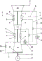
图1示意性地示出了用于实施根据本发明的方法的具有连续燃烧的燃气涡轮;Figure 1 schematically shows a gas turbine with continuous combustion for carrying out the method according to the invention;
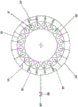
图2示意性地示出了具有焚烧器的第二燃烧器的截面;Figure 2 schematically shows a cross section of a second burner with a burner;
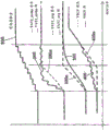
图3示意性地示出了具有焚烧器切换和温度和VIGV控制的操作构想。Figure 3 schematically shows an operational concept with burner switching and temperature and VIGV control.
具体实施方式Detailed ways
图1示意性地示出了用于实施根据本发明的方法的具有连续燃烧的燃气涡轮。其包括压缩机1、包括一定数量的焚烧器9和燃烧室4的第一燃烧器4'、第一涡轮7、包括一定数量的焚烧器9'和燃烧室15的第二燃烧室15',以及第二涡轮12。典型地,其包括发电机19,发电机19在燃气涡轮的冷端处,即是说,在压缩机1处,并且联接于燃气涡轮的轴18。第一燃烧器4'和第二燃烧器15'可为环形构架或筒形构架,同时第一涡轮7是可选的。Figure 1 schematically shows a gas turbine with continuous combustion for carrying out the method according to the invention. It comprises a compressor 1, a first burner 4' comprising a certain number of burners 9 and combustion chambers 4, a first turbine 7, a second combustion chamber 15' comprising a certain number of burners 9' and combustion chambers 15, and the second turbine 12 . Typically, it comprises a
筒形构架包括多个焚烧器,其中随后的筒以围绕涡轮轴的圆周的环形阵列布置,这允许了各个筒4,15的独立燃烧操作,并且这不在燃烧过程期间引起独立筒间的有害相互作用。The can frame includes a plurality of burners with subsequent cans arranged in an annular array around the circumference of the turbine shaft, which allows independent combustion operation of each can 4, 15, and which does not cause detrimental interactions between the individual cans during the combustion process effect.
环形构架包括布置成围绕涡轮轴的圆周的环形阵列的多个焚烧器,具有便于不同焚烧器之间的交叉点火的随后的环形燃烧室4,15。The annular framework includes a plurality of burners arranged in an annular array around the circumference of the turbine shaft, with subsequent annular combustion chambers 4, 15 that facilitate cross-firing between the different burners.
燃料、气体或油经由燃料供给部5引入到第一燃烧器4'的焚烧器4中,与在压缩机1中压缩的空气混合,并且在燃烧室4中燃烧。热气体6在随后的第一涡轮7中部分地膨胀,执行功。Fuel, gas or oil is introduced into the burner 4 of the first burner 4 ′ via the fuel supply 5 , mixed with the air compressed in the compressor 1 , and combusted in the combustion chamber 4 . The hot gas 6 is partially expanded in the subsequent first turbine 7, performing work.
一旦第二燃烧器在操作中,则附加燃料经由燃料供给部10添加至第二燃烧器15'的焚烧器9'中的部分地膨胀的气体8,并且在第二燃烧室15中燃烧。热气体11在随后的第二涡轮12中膨胀,执行功。排出气体13可有益地供给至联合循环发电站的废热锅炉或另一废热应用。Once the second burner is in operation, additional fuel is added via the
为了控制进入的质量流,压缩机1具有至少一排可变压缩机入口导叶14。In order to control the incoming mass flow, the compressor 1 has at least one row of variable compressor inlet guide vanes 14 .
作为附加选择,为了能够提高进入空气2的温度,可提供防冰线26,压缩空气3中的一些可通过其添加至进入空气2。为了控制,提供了防冰控制阀25。这通常在具有环境空气中的相对高空气湿度的冷天进行,以便预防压缩机1结冰的风险。As an additional option, in order to be able to increase the temperature of the intake air 2 , an
在该实例中,压缩空气3中的一些作为高压冷却空气22流出,经由高压冷却空气冷却器35再冷却,并且作为冷却空气22供给至第一燃烧器4'(未示出冷却空气线)和第一涡轮。In this example, some of the compressed air 3 flows out as high pressure cooling air 22, is recooled via a high pressure cooling air cooler 35, and is supplied as cooling air 22 to the first burner 4' (cooling air lines not shown) and first turbo.
供给至高压涡轮7的高压冷却空气22的质量流可在实例中借助于高压冷却空气控制阀21来控制。The mass flow of the high-pressure cooling air 22 supplied to the high-pressure turbine 7 can in the example be controlled by means of a high-pressure cooling air control valve 21 .
高压冷却空气22中的一些作为所谓的载体空气24供给至第二燃烧器15'的环形燃烧室15的焚烧器9'的焚烧器枪。载体空气24的质量流可借助于载体空气控制阀17来控制。Some of the high-pressure cooling air 22 is supplied as so-called carrier air 24 to the burner guns of the burner 9' of the annular combustion chamber 15 of the second burner 15'. The mass flow of the carrier air 24 can be controlled by means of the carrier air control valve 17 .
空气中的一些从压缩机1流出,部分地压缩,经由低压冷却空气冷却器36再冷却,并且作为冷却空气23供给至第二燃烧器15'的燃烧室15和第二涡轮。作为又一选择,冷却空气23的质量流可在实例中借助于冷却空气控制阀16来控制。Some of the air flows from the compressor 1, is partially compressed, recooled via a low pressure cooling air cooler 36, and supplied as cooling
燃烧器中的一个或更多个可构造为环形燃烧器,例如,具有大数量的独立焚烧器9或9',如在图2中经由第二燃烧器的实例大体示出的。这些焚烧器9或9'中的各个经由燃料分配系统和燃料供给部10,象征性地根据图2来供应有燃料。One or more of the burners may be configured as annular burners, eg, with a large number of individual burners 9 or 9', as generally shown in Figure 2 via the example of the second burner. Each of these burners 9 or 9 ′ is supplied with fuel, symbolically according to FIG. 2 , via a fuel distribution system and a
图2示出了例如穿过作为具有连续燃烧的燃气涡轮的环形燃烧室的第二燃烧室15',以及具有至独立焚烧器9'的燃料环干线30的燃料分配系统的截面。相同燃料分配相对于包括筒的第二燃烧室15是可能的。燃烧器9'设有独立的开/关阀37用于停用各个焚烧器9',用于控制燃料供给部10中至第一燃烧器4'和第二燃烧器15'的相应焚烧器9,9'的燃料流。Figure 2 shows a section through, for example, the second combustion chamber 15' as an annular combustion chamber with a continuous combustion gas turbine, and a fuel distribution system with a fuel ring trunk 30 to a separate burner 9'. The same fuel distribution is possible with respect to the second combustion chamber 15 comprising the canister. The burners 9' are provided with independent on/off
通过关闭独立的开/关阀37,至环形燃烧室15的独立焚烧器9'(或至每个筒的焚烧器)的燃料供给停止,并且可选的是燃料可分配至其余焚烧器9',其中总燃料质量流经由控制阀28控制。结果,操作中的焚烧器9的空气比λ减小。By closing the individual on/off
物件20示出了包括结合压缩机和涡轮的定子布置(未示出)的燃气涡轮的外壳。Item 20 shows a casing of a gas turbine including a stator arrangement (not shown) incorporating a compressor and turbine.
图3示出了关于常规过程(表示为原来的)的焚烧器开启/切断和温度和VIGV控制的操作构想。在卸载燃气涡轮时,单个第二级焚烧器100以如下方式连续切断,使得其余的焚烧器100在与在较高发动机负载下的相同热气体温度下操作,从而保持相同低CO排放。相对于原来的标准操作构想,TAT2_avg 300减小以便保持局部最大局部涡轮出口温度。只要它们与最高焚烧器热气体温度相关,则TAT2_strike 200恒定。Figure 3 shows an operational concept for burner on/off and temperature and VIGV control for a conventional process (shown as original). When unloading the gas turbine, the single second stage combustor 100 is continuously switched off in such a way that the remaining combustors 100 operate at the same hot gas temperature as at higher engine loads, maintaining the same low CO emissions. Relative to the original standard operating concept, TAT2_avg 300 is reduced in order to maintain the local maximum local turbine outlet temperature. TAT2_strike 200 is constant as long as they relate to the highest incinerator hot gas temperature.
这通过同时打开VIGV400以便保持相同功率输出来实现。This is achieved by turning on the VIGV400 at the same time in order to maintain the same power output.
在质量上考虑图3中相对于原方法和根据本发明的新操作方法所示的曲线。曲线(100-400)的不同形状是示意性的,并且形成了用于实现本发明的目的的基础。Consider qualitatively the curves shown in FIG. 3 with respect to the original method and the new method of operation according to the invention. The different shapes of the curves (100-400) are schematic and form the basis for the purpose of the present invention.
部件列表Parts List
1 压缩机1 compressor
2 进入空气2 Enter the air
3 压缩空气3 Compressed air
4 第一燃烧室(环形燃烧室/筒)4 The first combustion chamber (annular combustion chamber/tube)
5 燃料供给部5 Fuel supply section
6 热气体6 hot gas
7 第一涡轮7 first turbo
7 部分膨胀的热气体7 Partially expanded hot gas
9 第一燃烧器的焚烧器9 Burner of the first burner
10 燃料供给部10 Fuel supply section
11 热气体11 Hot gas
12 第二涡轮12 Second turbo
13 排出气体(用于废热锅炉)13 Exhaust gas (for waste heat boiler)
14 可变压缩机入口导叶14 Variable compressor inlet guide vanes
15 第二燃烧室(环形燃烧室/筒)15 Second combustion chamber (annular combustion chamber/tube)
16 低压冷却空气控制阀16 Low pressure cooling air control valve
17 载体空气控制阀17 Carrier Air Control Valve
18 轴18 axes
19 发电机19 Generator
20 燃气涡轮的外壳体20 Outer casing of gas turbine
21 高压冷却空气控制阀21 High pressure cooling air control valve
22 高压冷却空气22 High pressure cooling air
23 冷却空气23 Cooling air
24 载体空气24 Carrier Air
25 防冰控制阀25 Anti-icing control valve
26 防冰线26 Anti-icing line
28 燃料控制阀28 Fuel control valve
29 燃料供给部29 Fuel Supply Department
30 燃料环干线30 Fuel Ring Trunk
35 高压冷却空气冷却器35 High pressure cooling air cooler
36 低压冷却空气冷却器36 Low pressure cooling air cooler
37 独立开/关阀37 Independent on/off valve
TAT 涡轮排气温度TAT turbine exhaust temperature
TAT1 第一涡轮的涡轮排气(出口)温度TAT1 Turbine exhaust (outlet) temperature of the first turbine
TAT2 第二涡轮的涡轮排气(出口)温度Turbine exhaust (outlet) temperature of TAT2 second turbine
TIT 涡轮入口温度TIT turbine inlet temperature
TIT1 第一涡轮的涡轮入口温度TIT1 Turbine inlet temperature of the first turbine
TIT2 第二涡轮的涡轮入口温度Turbine inlet temperature of TIT2 2nd turbine
4’ 第一燃烧器4’ first burner
9’ 第二燃烧器的焚烧器9’ burner for second burner
15’ 第二燃烧器15' second burner
100 焚烧器数量100 Number of Incinerators
200 TAT2_strike新或发明200 TAT2_strike new or invented
200a TAT2_strike原来或现有技术200a TAT2_strike original or prior art
300 TAT2_avg(avg=平均)新或发明300 TAT2_avg (avg=average) new or invented
300a TAT2_avg原来或现有技术300a TAT2_avg original or prior art
400 VIGV新或发明400 VIGV new or invented
400a VIGV原来或现有技术400a VIGV original or prior art
VIGV 压缩机入口导叶VIGV compressor inlet guide vanes
AEV 预混焚烧器,尤其用于第一燃烧器AEV premix burners, especially for first burners
SEV 再热焚烧器,尤其用于第二燃烧器。SEV reheat burners, especially for secondary burners.
Claims (14)
Applications Claiming Priority (3)
| Application Number | Priority Date | Filing Date | Title |
|---|---|---|---|
| EP13155823.1A EP2600063A3 (en) | 2013-02-19 | 2013-02-19 | Method of operating a gas turbine with staged and/or sequential combustion |
| EP13155823.1 | 2013-02-19 | ||
| PCT/EP2014/053197 WO2014128146A1 (en) | 2013-02-19 | 2014-02-19 | Method of operating a gas turbine with staged and/or sequential combustion |
Publications (2)
| Publication Number | Publication Date |
|---|---|
| CN104981663A CN104981663A (en) | 2015-10-14 |
| CN104981663B true CN104981663B (en) | 2020-12-22 |
Family
ID=47722151
Family Applications (1)
| Application Number | Title | Priority Date | Filing Date |
|---|---|---|---|
| CN201480009475.5A Active CN104981663B (en) | 2013-02-19 | 2014-02-19 | Method of operating a gas turbine with staged and/or continuous combustion |
Country Status (6)
| Country | Link |
|---|---|
| US (1) | US20160018111A1 (en) |
| EP (2) | EP2600063A3 (en) |
| JP (1) | JP2016513211A (en) |
| CN (1) | CN104981663B (en) |
| RU (1) | RU2665773C2 (en) |
| WO (1) | WO2014128146A1 (en) |
Families Citing this family (33)
| Publication number | Priority date | Publication date | Assignee | Title |
|---|---|---|---|---|
| EP2789915A1 (en) * | 2013-04-10 | 2014-10-15 | Alstom Technology Ltd | Method for operating a combustion chamber and combustion chamber |
| EP2829705A1 (en) * | 2013-07-24 | 2015-01-28 | Alstom Technology Ltd | Gas turbine and method of controlling gas turbine |
| EP2835516A1 (en) * | 2013-08-08 | 2015-02-11 | Alstom Technology Ltd | Gas turbine with improved part load emissions behavior |
| EP2857656A1 (en) * | 2013-10-01 | 2015-04-08 | Alstom Technology Ltd | Gas turbine with cooling air cooling system and method for operation of a gas turbine at low part load |
| EP2902606B1 (en) | 2014-01-31 | 2019-01-02 | Ansaldo Energia IP UK Limited | Method for operating a gas turbine at part load |
| EP3061944A1 (en) | 2015-02-26 | 2016-08-31 | General Electric Technology GmbH | Method for controlling the operation of a gas turbine with sequential combustion |
| US10330015B2 (en) * | 2015-09-25 | 2019-06-25 | General Electric Company | Transient emission temperature control of turbine systems |
| JP6740375B2 (en) | 2016-05-12 | 2020-08-12 | シーメンス アクティエンゲゼルシャフト | A method for selective combustor control to reduce emissions. |
| CN106354938A (en) * | 2016-08-30 | 2017-01-25 | 潍柴动力股份有限公司 | Engine power classification method |
| US10062579B2 (en) * | 2016-10-07 | 2018-08-28 | Applied Materials, Inc. | Selective SiN lateral recess |
| US10280844B2 (en) * | 2016-11-17 | 2019-05-07 | General Electric Company | Control systems for controlling power systems based on fuel consumption and related program products |
| US11092085B2 (en) | 2017-03-14 | 2021-08-17 | General Electric Company | Method and system for controlling a sequential gas turbine engine |
| EP3376003B1 (en) * | 2017-03-14 | 2020-04-29 | General Electric Company | Method and system for controlling a sequential gas turbine engine |
| US20180286707A1 (en) * | 2017-03-30 | 2018-10-04 | Lam Research Corporation | Gas additives for sidewall passivation during high aspect ratio cryogenic etch |
| EP3447379B1 (en) * | 2017-08-25 | 2022-01-26 | Ansaldo Energia IP UK Limited | Method for operating a gas turbine plant and gas turbine plant |
| EP3477080A1 (en) | 2017-10-30 | 2019-05-01 | Siemens Aktiengesellschaft | Method of controlling a gas turbine engine |
| EP3477079A1 (en) * | 2017-10-30 | 2019-05-01 | Siemens Aktiengesellschaft | Method of controlling a gas turbine engine |
| EP3524799A1 (en) | 2018-02-13 | 2019-08-14 | Siemens Aktiengesellschaft | Method for operating a burner assembly of a gas turbine |
| EP3683426B1 (en) * | 2019-01-15 | 2023-05-03 | Ansaldo Energia Switzerland AG | Method for operating a gas turbine power plant and gas turbine power plant |
| US11156164B2 (en) | 2019-05-21 | 2021-10-26 | General Electric Company | System and method for high frequency accoustic dampers with caps |
| US11174792B2 (en) | 2019-05-21 | 2021-11-16 | General Electric Company | System and method for high frequency acoustic dampers with baffles |
| JP7231493B2 (en) * | 2019-06-12 | 2023-03-01 | 三菱重工業株式会社 | Control device, gas turbine, control method and program |
| EP3832091B1 (en) * | 2019-12-04 | 2023-06-14 | Ansaldo Energia Switzerland AG | Gas turbine assembly for power plant application fed by at least two different fuels (fuel-gas or fuel-oil) and a method for operating this assembly when switching fuels or when operating this assembly with fuel-oil |
| EP3845813B1 (en) * | 2019-12-31 | 2024-04-03 | Ansaldo Energia Switzerland AG | Method for operating a gas turbine assembly and gas turbine assembly |
| US11203986B1 (en) * | 2020-06-08 | 2021-12-21 | General Electric Company | Systems and methods for extended emissions compliant operation of a gas turbine engine |
| CN114791104B (en) * | 2021-01-25 | 2026-03-10 | 李华玉 | Dual-fuel high-temperature heat source and dual-fuel gas turbine device |
| CN113834095B (en) * | 2021-11-02 | 2023-02-07 | 西安热工研究院有限公司 | A Gas Turbine Annular Combustor Based on Detonation Combustion |
| EP4206452B1 (en) * | 2021-12-30 | 2026-03-11 | Ansaldo Energia Switzerland AG | Method for operating a gas turbine assembly for a power plant and gas turbine assembly for a power plant |
| US11940151B2 (en) | 2022-01-12 | 2024-03-26 | General Electric Company | Combustor with baffle |
| US12018839B2 (en) | 2022-10-20 | 2024-06-25 | General Electric Company | Gas turbine engine combustor with dilution passages |
| EP4390226A1 (en) | 2022-12-20 | 2024-06-26 | General Electric Company | Gas turbine engine combustor with a set of dilution passages |
| US12158270B2 (en) | 2022-12-20 | 2024-12-03 | General Electric Company | Gas turbine engine combustor with a set of dilution passages |
| CN116576485B (en) * | 2023-05-15 | 2025-12-23 | 清航空天(北京)科技有限公司 | Knocking combustion structure and knocking engine |
Citations (3)
| Publication number | Priority date | Publication date | Assignee | Title |
|---|---|---|---|---|
| US6463741B1 (en) * | 1999-11-03 | 2002-10-15 | Alstom (Switzerland) Ltd | Method for operating a power plant |
| CN1912367A (en) * | 2005-08-10 | 2007-02-14 | 通用电气公司 | Combustion gas turbine systems and operation method thereof |
| CN102536467A (en) * | 2010-12-17 | 2012-07-04 | 通用电气公司 | Gas turbine engine and method of operating thereof |
Family Cites Families (18)
| Publication number | Priority date | Publication date | Assignee | Title |
|---|---|---|---|---|
| CH687269A5 (en) | 1993-04-08 | 1996-10-31 | Abb Management Ag | Gas turbine group. |
| EP0646704B1 (en) | 1993-09-06 | 1997-11-26 | Asea Brown Boveri Ag | Method for controlling a gas turbine plan equipped with two combustion chambers |
| DE59309644D1 (en) | 1993-09-06 | 1999-07-15 | Asea Brown Boveri | Process for creating a partial load operation for a gas turbine group |
| DE4446610A1 (en) | 1994-12-24 | 1996-06-27 | Abb Management Ag | Process for operating a gas turbine group |
| DE19537637A1 (en) * | 1995-10-10 | 1997-04-17 | Asea Brown Boveri | Process for operating a power plant |
| EP0921292B1 (en) | 1997-12-08 | 2003-09-10 | ALSTOM (Switzerland) Ltd | Method for controlling a gas turbine group |
| RU2146769C1 (en) * | 1998-11-23 | 2000-03-20 | Кубанский государственный технологический университет | Gas turbine plant |
| JP3828738B2 (en) * | 2000-10-31 | 2006-10-04 | 株式会社日立製作所 | Gas turbine fuel control system |
| DE102004005476A1 (en) * | 2003-02-11 | 2004-12-09 | Alstom Technology Ltd | Process for operating a gas turbine group |
| ES2547641T3 (en) * | 2003-02-11 | 2015-10-07 | Alstom Technology Ltd | Procedure to operate a group of gas turbines |
| EP1655590B1 (en) * | 2004-11-09 | 2016-02-03 | Alstom Technology Ltd | Method for determining the mass averaged temperature across a flow section of a gas stream in a gas turbine |
| US8495883B2 (en) * | 2007-04-05 | 2013-07-30 | Siemens Energy, Inc. | Cooling of turbine components using combustor shell air |
| US8015826B2 (en) * | 2007-04-05 | 2011-09-13 | Siemens Energy, Inc. | Engine brake for part load CO reduction |
| ES2457819T3 (en) * | 2007-12-10 | 2014-04-29 | Alstom Technology Ltd | Procedure for the regulation of a gas turbine in a power plant |
| WO2009109446A1 (en) * | 2008-03-05 | 2009-09-11 | Alstom Technology Ltd | Method for regulating a gas turbine in a power plant and power plant to carry out the method |
| CH700796A1 (en) * | 2009-04-01 | 2010-10-15 | Alstom Technology Ltd | Method for CO-emission operation of a gas turbine with sequential combustion and gas turbine with improved part-load emission behavior. |
| US8601820B2 (en) * | 2011-06-06 | 2013-12-10 | General Electric Company | Integrated late lean injection on a combustion liner and late lean injection sleeve assembly |
| JP6253066B2 (en) * | 2012-06-29 | 2017-12-27 | アンサルド エネルジア スウィッツァーランド アクチエンゲゼルシャフトAnsaldo Energia Switzerland AG | Method of partial load CO reduction operation and gas turbine for a two-stage combustion gas turbine |
-
2013
- 2013-02-19 EP EP13155823.1A patent/EP2600063A3/en not_active Withdrawn
-
2014
- 2014-02-19 CN CN201480009475.5A patent/CN104981663B/en active Active
- 2014-02-19 WO PCT/EP2014/053197 patent/WO2014128146A1/en not_active Ceased
- 2014-02-19 EP EP14705761.6A patent/EP2959229B1/en active Active
- 2014-02-19 JP JP2015558429A patent/JP2016513211A/en active Pending
- 2014-02-19 RU RU2015139836A patent/RU2665773C2/en active
-
2015
- 2015-07-31 US US14/814,864 patent/US20160018111A1/en not_active Abandoned
Patent Citations (3)
| Publication number | Priority date | Publication date | Assignee | Title |
|---|---|---|---|---|
| US6463741B1 (en) * | 1999-11-03 | 2002-10-15 | Alstom (Switzerland) Ltd | Method for operating a power plant |
| CN1912367A (en) * | 2005-08-10 | 2007-02-14 | 通用电气公司 | Combustion gas turbine systems and operation method thereof |
| CN102536467A (en) * | 2010-12-17 | 2012-07-04 | 通用电气公司 | Gas turbine engine and method of operating thereof |
Also Published As
| Publication number | Publication date |
|---|---|
| US20160018111A1 (en) | 2016-01-21 |
| EP2600063A3 (en) | 2014-05-07 |
| EP2959229A1 (en) | 2015-12-30 |
| WO2014128146A1 (en) | 2014-08-28 |
| EP2959229B1 (en) | 2020-10-14 |
| CN104981663A (en) | 2015-10-14 |
| EP2600063A2 (en) | 2013-06-05 |
| JP2016513211A (en) | 2016-05-12 |
| RU2015139836A (en) | 2017-03-24 |
| RU2665773C2 (en) | 2018-09-04 |
Similar Documents
| Publication | Publication Date | Title |
|---|---|---|
| CN104981663B (en) | Method of operating a gas turbine with staged and/or continuous combustion | |
| JP6205118B2 (en) | Method and apparatus for optimizing turbine system operation under flexible loads | |
| US8434312B2 (en) | Gas turbine with improved part load emissions behavior | |
| EP2843211B1 (en) | Gas turbine with improved part load emissions behaviour and method thereof | |
| JP5676073B2 (en) | Gas turbine engine combustor assembly with integrated control valve | |
| US20140150438A1 (en) | System and method for operating a gas turbine in a turndown mode | |
| JP6253066B2 (en) | Method of partial load CO reduction operation and gas turbine for a two-stage combustion gas turbine | |
| US20140123651A1 (en) | System for providing fuel to a combustor assembly in a gas turbine engine | |
| US11092085B2 (en) | Method and system for controlling a sequential gas turbine engine | |
| JP2003328779A (en) | Fuel supply system and air-fuel ratio adjusting method for gas turbine and gas turbine |
Legal Events
| Date | Code | Title | Description |
|---|---|---|---|
| C06 | Publication | ||
| PB01 | Publication | ||
| C10 | Entry into substantive examination | ||
| SE01 | Entry into force of request for substantive examination | ||
| CB02 | Change of applicant information |
Address after: Baden, Switzerland Applicant after: ALSTOM TECHNOLOGY LTD Address before: Baden, Switzerland Applicant before: Alstom Technology Ltd. |
|
| COR | Change of bibliographic data | ||
| TA01 | Transfer of patent application right | ||
| TA01 | Transfer of patent application right |
Effective date of registration: 20171127 Address after: London, England Applicant after: Security energy UK Intellectual Property Ltd Address before: Baden, Switzerland Applicant before: ALSTOM TECHNOLOGY LTD |
|
| GR01 | Patent grant | ||
| GR01 | Patent grant |