JP5678317B2 - Thermally optimized microwave channel multiplexer and signal repeater comprising at least one such multiplexer - Google Patents
Thermally optimized microwave channel multiplexer and signal repeater comprising at least one such multiplexer Download PDFInfo
- Publication number
- JP5678317B2 JP5678317B2 JP2010195547A JP2010195547A JP5678317B2 JP 5678317 B2 JP5678317 B2 JP 5678317B2 JP 2010195547 A JP2010195547 A JP 2010195547A JP 2010195547 A JP2010195547 A JP 2010195547A JP 5678317 B2 JP5678317 B2 JP 5678317B2
- Authority
- JP
- Japan
- Prior art keywords
- filter
- filters
- plate
- multiplexer
- outer peripheral
- Prior art date
- Legal status (The legal status is an assumption and is not a legal conclusion. Google has not performed a legal analysis and makes no representation as to the accuracy of the status listed.)
- Expired - Fee Related
Links
Images


Classifications
-
- H—ELECTRICITY
- H01—ELECTRIC ELEMENTS
- H01P—WAVEGUIDES; RESONATORS, LINES, OR OTHER DEVICES OF THE WAVEGUIDE TYPE
- H01P1/00—Auxiliary devices
- H01P1/30—Auxiliary devices for compensation of, or protection against, temperature or moisture effects ; for improving power handling capability
-
- H—ELECTRICITY
- H01—ELECTRIC ELEMENTS
- H01P—WAVEGUIDES; RESONATORS, LINES, OR OTHER DEVICES OF THE WAVEGUIDE TYPE
- H01P1/00—Auxiliary devices
- H01P1/20—Frequency-selective devices, e.g. filters
- H01P1/213—Frequency-selective devices, e.g. filters combining or separating two or more different frequencies
- H01P1/2138—Frequency-selective devices, e.g. filters combining or separating two or more different frequencies using hollow waveguide filters
Landscapes
- Non-Reversible Transmitting Devices (AREA)
- Cooling Or The Like Of Electrical Apparatus (AREA)
- Transmitters (AREA)
- Control Of Motors That Do Not Use Commutators (AREA)
Description
本発明は熱的に最適化されたマイクロ波チャンネル多重化装置及び、少なくとも1つの多重化装置を備える信号反復装置に関する。それは特に衛星通信の分野に、そしてとりわけ人工衛星に搭載される信号反復装置に適用される。 The present invention relates to a thermally optimized microwave channel multiplexer and a signal repeater comprising at least one multiplexer. It applies in particular to the field of satellite communications, and in particular to signal repeaters mounted on artificial satellites.
例えば図1に表わされるように、人工衛星2に搭載される信号反復装置1は、地上局と特定の地理的領域に位置するユーザー間で、信号を伝達、増幅、及び経路指定するための、マイクロ波信号送信及び受信チェーンを一般に備える。受信の際、受信アンテナ3により受信された信号は、受信フィルター5を用いて受信機4に送られ、次に増幅器6により増幅されて、伝送フィルター7を通った後に送信アンテナ8によって再伝送される。技術的な増幅の理由として、増幅前には、受信信号の帯域幅は従来から(入力マルチプレクサーを表わす)IMUXと呼ばれる、逆多重化装置9を用いてユーザーのチャンネル幅に等しい、狭められた幅の幾つかのサブバンドに分割され、増幅後には、増幅された信号は単独の広帯域信号へと再結合される。単独の広帯域出力信号への信号再結合は、幾つかの要素フィルター11を含み、各要素フィルターが所定の中心周波数及び帯域幅を有する、従来から(出力マルチプレクサーを表わす)OMUXと呼ばれる、出力多重化装置10を用いて一般的に行われる。
For example, as shown in FIG. 1, a
例えば図2に表わされるように、各フィルター11は信号入力13及び信号出力14を備え、それらのフィルターは全てのチャンネルの出力14を一緒につなぐ、マニホールドと呼ばれる横断導波管16により、共通の出力ポート15に並列に接続されている。各フィルター11は無線周波数RF信号がその中を移動するチャンネルを形成するように、少なくとも1つの内部共振空洞又は、例えば連結アイリス絞りを用いて共に連結される、幾つかの内部共振空洞を備える。
For example, as shown in FIG. 2, each
OMUXの各種フィルター11は、従来から各チャンネルの長手方向Z軸が支持体12の平面に実質的に平行であるような方法で、熱伝導性で一般に金属の共通支持体12の上に、水平かつ相互に平行に固定される。各空洞の長手方向の壁は、そのとき直接又は固定ブラケット17によって支持体12と接触し、それによって熱伝導により、フィルター11の空洞によって放散される熱エネルギーを支持体12の方へ排出することを可能にする。従来、熱流束は衛星のパネル上に配置されるヒートパイプに向かって、フィルター11に直角に支持体12を横断する。
Various OMUX
大きさをそれに対して決定される周波数帯域内の、フィルターの動作に対応する公称動作モードにおいて、この熱エネルギーは基本的にフィルターの壁におけるジュール効果に起因する、表皮効果による損失に起因するものであり、これらの損失は伝導によってフィルターの内側から外側に放散される。OMUXのフィルターの周りの送信周波数における異常に相当する、「オフバンド(off−band)」と呼ばれる動作モードにおいて、フィルターはそれに対して大きさを決定される周波数帯域の外側で動作する。このオフバンド動作モードにおいて、フィルターは信号のエネルギーの大半を吸収し放散する。オフバンド動作モードにおいてフィルターにより放散される出力は、公称動作モードにおける出力よりも約3倍大きい。OMUXが熱的に補償されたタイプであり、各フィルターが、空洞の容積の制御を可能にし、従って温度に応じて動作周波数の調整を可能にするフレキシブルな膜を備える場合、この大きな出力の放散は、この部分の抵抗性が高く大きな温度勾配を生じるため、フレキシブルな膜に対して不都合となる影響を有し得る。 In a nominal mode of operation corresponding to the operation of the filter in the frequency band of which the magnitude is determined, this thermal energy is due to losses due to the skin effect, essentially due to the Joule effect on the filter wall. These losses are dissipated from the inside to the outside of the filter by conduction. In an operating mode called “off-band”, which corresponds to an anomaly in the transmission frequency around the OMUX filter, the filter operates outside the frequency band that is sized for it. In this off-band mode of operation, the filter absorbs and dissipates most of the signal energy. The output dissipated by the filter in the off-band mode of operation is about 3 times greater than the output in the nominal mode of operation. If the OMUX is a thermally compensated type and each filter has a flexible membrane that allows control of the volume of the cavity and thus allows adjustment of the operating frequency as a function of temperature, this large output dissipation Can have a detrimental effect on flexible membranes because of the high resistance of this portion and the generation of large temperature gradients.
OMUXのフィルターのチャンネルは、従って常にオフバンド・モードに対して熱的に大きさを決められる。 The OMUX filter channel is therefore always thermally sized for the off-band mode.
OMUXの水平構造は、チャンネルの温度勾配の制御に対して非常に適しているが、一方で、500W以上の非常に大きな出力を必要とする用途の場合、この構造は衛星のパネルのヒートパイプに対する、オフバンド・チャンネルのインターフェースにおいて相当に大きな熱流束密度を生じ、それはこれらのヒートパイプが乾燥する危険性を意味し、他方で、この構造は支持体の平面内で大きな設置面積を必要とし、これは非常に限られた占有スペース内での搭載機器配置の場合に不都合となるため、宇宙応用の枠組内で遭遇する新たな要求事項への適応に対して制限されたままである。 The horizontal structure of the OMUX is very suitable for controlling the temperature gradient of the channel, while for applications that require a very large output of 500W or more, this structure can be used for satellite panel heat pipes. , Resulting in a considerably higher heat flux density at the off-band channel interface, which means the risk of these heat pipes drying out, while this structure requires a large footprint in the plane of the support, This is inconvenient for placement of on-board equipment in a very limited occupancy space and remains limited to adapting to new requirements encountered within the framework of space applications.
ヒートパイプに対する流束密度の制約の問題を解決するために、従来の開発されたヒートパイプはとても大きく、これによって衛星の搭載機器の配置に不都合となっている。 Conventionally developed heat pipes are very large to solve the problem of flux density constraints on heat pipes, which makes it inconvenient for placement of satellite onboard equipment.
OMUXの占有スペースの問題を解決し、その設置を最適化するために、水平構造に対して垂直構造が好まれ得るが、しかしそれは水平構造で得られるよりも遥かに大きい温度勾配を生じる。現在、この温度勾配を解決するための既知の解決策は、各フィルターの壁の厚さを増すことにより、各チャンネルの伝熱断面積を増加させることにある。しかしながら、これはOMUXの質量を大幅に増加させる、結果として生じる追加的材料を必要とし、これは宇宙応用に対して不都合であり、あるいは実に重大障害となる。 In order to solve the OMUX footprint problem and optimize its installation, a vertical structure may be preferred over a horizontal structure, but it produces a much greater temperature gradient than can be obtained with a horizontal structure. Currently, a known solution to solve this temperature gradient is to increase the heat transfer cross section of each channel by increasing the wall thickness of each filter. However, this requires the resulting additional material that greatly increases the mass of the OMUX, which is inconvenient for space applications or indeed a serious obstacle.
本発明の目的は、特に非常に大きな出力を必要とする用途の場合に、オフバンド・チャンネルのインターフェースにおいて熱流束密度の低減を可能にする、質量において最適化されたマイクロ波チャンネル多重化装置を生み出すことである。 The object of the present invention is to provide a mass-optimized microwave channel multiplexer that enables a reduction in heat flux density at the off-band channel interface, especially for applications that require very high power. It is to produce.
このために、本発明は、横断導波管によって共通の出力ポートに並列に接続され、各フィルターが全てのフィルターに共通の支持体に固定された下端部、及び支持体から離れた上端部を含む、幾つかの要素フィルターと、外側の周囲壁と、内部チャンネルを定義する少なくとも1つの内部空洞と、内部空洞に接続された信号入力と、横断導波管に接続された信号出力とを備え、それがさらに少なくとも1つの熱伝導板を含み、前記少なくとも2つのフィルターの各々外側の周囲壁につながれ、板がフィルターの上端部のレベルに固定されている、機械的及び熱的に少なくとも2つのフィルターに連結された伝導放射装置を備えることを特徴とする、マイクロ波チャンネル多重化装置に関する。 To this end, the present invention has a lower end connected to a common output port in parallel by a transverse waveguide, each filter being fixed to a common support for all filters, and an upper end remote from the support. Including several element filters, an outer peripheral wall, at least one internal cavity defining an internal channel, a signal input connected to the internal cavity, and a signal output connected to a transverse waveguide At least two mechanically and thermally, further comprising at least one heat conducting plate, connected to the outer peripheral wall of each of the at least two filters, the plate being fixed at the level of the upper end of the filter The present invention relates to a microwave channel multiplexer comprising a conduction radiation device connected to a filter.
板はくり抜きを備え、前記フィルターの外側周囲壁が対応する板のくり抜きの中にぴったりはまるような方法で、前記少なくとも2つのフィルターの外側周囲壁と協調することが有利である。 Advantageously, the plates are provided with cutouts and cooperate with the outer peripheral walls of the at least two filters in such a way that the outer peripheral walls of the filter fit snugly into the cutouts of the corresponding plates.
各フィルターは外側の周囲壁に固定された外部の環状カラーを備え、板は前記少なくとも2つのフィルターのカラーに取り付けられ、固定されることが望ましい。 Preferably, each filter comprises an outer annular collar secured to the outer peripheral wall, and the plate is attached and secured to the collar of the at least two filters.
一実施形態において、各フィルターの上端部は長手方向のチャンネルを閉じるためのカバーを備え、板は環状カラーと前記少なくとも2つのフィルターのカバーとの間に固定される。 In one embodiment, the upper end of each filter comprises a cover for closing the longitudinal channel, and the plate is fixed between the annular collar and the cover of the at least two filters.
板は、冷却液を循環させるための回路を備える伝熱材料を含む、小形のヒートパイプを装備し得ることが有利である。 Advantageously, the plate may be equipped with a small heat pipe containing a heat transfer material with a circuit for circulating the coolant.
一実施形態によれば、板はそれぞれ下側と上側にある2つの異なる壁と、2つの壁の間に固定された小形のヒートパイプとを備え得る。 According to one embodiment, the plate may comprise two different walls on the lower and upper sides, respectively, and a small heat pipe fixed between the two walls.
板は、金属材料あるいは、伝導性ファイバーで強化された金属マトリックスを有する複合材料の中から選ばれた、伝熱材料で作られることが有利である。 The plate is advantageously made of a heat transfer material selected from a metal material or a composite material having a metal matrix reinforced with conductive fibers.
伝導放射装置は、全てのフィルターの外側周囲壁につながれ、固定された単独の熱伝導板を備え得る。 The conducted radiating device may comprise a single heat conducting plate fixed and connected to the outer peripheral wall of all filters.
代わりに、伝導放射装置は少なくとも2つのフィルターの第1組と、少なくとも2つのフィルターの第2組の外側周囲壁にそれぞれつながれた、少なくとも2枚の熱伝導板を備え得る。伝導放射装置が2枚の板を備える場合、2枚の板は相互に熱的に連結され得る。 Alternatively, the conducted radiation device may comprise at least two heat conducting plates respectively connected to the outer peripheral walls of the first set of at least two filters and the second set of at least two filters. If the conducted radiation device comprises two plates, the two plates can be thermally connected to each other.
一実施形態によれば、要素フィルターは共通の支持体上に平行に配置され、共通の支持体に対して直角な前後軸を有し、伝導放射装置はフィルターの各チャンネルの単独の空洞に熱的に連結される。 According to one embodiment, the element filters are arranged in parallel on a common support and have a longitudinal axis perpendicular to the common support, and the conducted radiating device is heated in a single cavity in each channel of the filter. Connected.
別の実施形態によれば、要素フィルターは共通の支持体上に平行に配置され、共通の支持体に対して平行な前後軸を有し、伝導放射装置はフィルターの各チャンネルの全ての空洞に熱的に連結される。 According to another embodiment, the element filters are arranged in parallel on a common support and have a longitudinal axis parallel to the common support, and the conducted radiation device is in all cavities of each channel of the filter. Thermally coupled.
本発明はまた、少なくとも1つのそのような多重化装置を備える、信号反復装置にも関する。 The invention also relates to a signal repeater comprising at least one such multiplexer.
本発明のその他の特徴及び利点は、添付の略図に関連して、純粋に例示的な限定されない例を用いて与えられる、以下に続く記述においてはっきりと明らかになるであろう。 Other features and advantages of the present invention will become apparent in the description that follows, given purely by way of non-limiting example in connection with the accompanying schematic drawings.
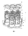
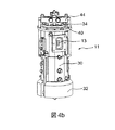
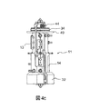
図3の例において表わされている、OMUXと呼ばれるマイクロ波チャンネル多重化装置は、チャンネルの垂直構造に従って配置された5つのフィルター11の組を備える。図4a、4b、及び4cの詳細図において表わされる各フィルター11は、長手方向Z軸に従って、外側の周囲壁30、台座32内に位置する下端部31、上部の閉塞カバー34を備える上端部33、フレキシブルで変形可能な部分及び固定カラーを備え得るカバー34、そして両端部31、33の間に配置された少なくとも1つの内部空洞35、36を含む。図4aの限定されない例において、表わされているフィルターはZ軸に沿って重ねられている2つの内部空洞35、36を備える。フィルターの位相幾何学の変形において、空洞の数及び幾何学的形状は異なり得る。例えば、2つがZ軸に沿って整列し、3番目がZ軸に直交して片側において連結される、3つの空洞を有するフィルターを用いることが可能である。2つの内部空洞は図示されていない絞りにより、共に電気的に連結されている。フィルター11は上部空洞36につながれた無線周波数信号RF用の入力インターフェース13と、下部空洞35に接続された無線周波数信号RF用の出力インターフェース14とを備える。OMUXの各フィルター11の台座32は、各フィルターの前後軸が支持体に対して実質的に直角であるような方法で、共通の支持体12に固定されている。各フィルターはOMUXのフィルターからフィルターへと変わる、所定の中心周波数において動作する。選ばれた技術のタイプによって、フィルターはインバールのような低い熱膨張係数を有する材料で作られ得るか、あるいはフィルターは随意的に温度補償されることができ、及び/又は随意的に誘電共振器を備える。図4b及び4cの例において、表わされているフィルターは温度補償され、各フィルター11のカバー34は、フィルターの動作周波数を安定させるように、温度に応じてフィルター11の内部空洞35、36の容積を自動的に変更可能にする、温度補償装置44を備える。
The microwave channel multiplexer called OMUX, represented in the example of FIG. 3, comprises a set of five
この垂直構造は、支持体12の観点から水平構造よりも小形であるという利点を示すが、しかしながら各フィルターの空洞の数が1よりも多い場合、支持体12と接触するのは下部の空洞35だけであり、支持体12から最も遠い部分の熱を排出するのは困難であるという欠点を含む。実際、上部の空洞36におけるエネルギー放散から生じる熱流束は、支持体12において排出される前に下部の空洞35を通り抜けなければならない。支持体12に接する下部の空洞35は、従ってそれ自体の熱流束及び上部の空洞36により放散される熱流束を吸収しなければならず、それによってチャンネルの熱制御の観点から重い制約を生じる。この垂直構造はそれゆえフィルターの1つがオフバンド動作モードにあるとき、相当に増加した大きさをとる、大きな熱勾配を示す。この場合、オフバンド・チャンネルの高い位置の部分は非常に高温に達し、一方で公称モードにおいて動作する、このオフバンド・チャンネルに近いチャンネルは、より低い温度に留まる。
This vertical structure has the advantage of being smaller than the horizontal structure from the standpoint of the
熱流束の拡散を改善し、オフバンド・モードにおいてOMUX内の熱勾配を減らすため、本発明は望ましくはそれらの最も高温の部分のレベルで、複数のチャンネルを共に機械的及び熱的に連結し、そしてOMUXの外側の環境との放射交換を増すことにある。図3に表わされている例示的な実施形態は、チャンネルの垂直構造の最も極限的な場合に関するが、しかし本発明はまた図8の例に表わされているように、非常に大きい出力を必要とする用途の場合の水平構造にも適用できる。 In order to improve heat flux diffusion and reduce thermal gradients in the OMUX in off-band mode, the present invention preferably connects the channels together mechanically and thermally at the level of their hottest portion. And to increase radiation exchange with the environment outside the OMUX. The exemplary embodiment represented in FIG. 3 relates to the most extreme case of the vertical structure of the channel, but the present invention also has a very large output, as represented in the example of FIG. It can also be applied to a horizontal structure in the case of applications that require
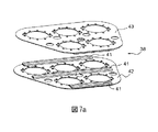
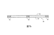
図3の例において、最も高温の部分は、各フィルター11の上部空洞36を閉じているカバー34のレベルの、チャンネル上部である。本発明は、フィルターの外側の周囲壁30上に、少なくとも1つの熱伝導板38を含む伝導放射装置を固定することにある。図3に表わされている実施形態によれば、伝導放射板と呼ばれる板38はその厚み全体を貫通するくり抜き39を備え、くり抜きは、各フィルター11の外側周囲壁30が対応する板38のくり抜き39の中にぴったりはまるような方法で、各フィルター11の外側周囲壁と協調している。有利なことに、外部の環状カラー40は各フィルターの外側周囲壁の上に、例えば各フィルター11のチャンネルの上端部33に配置され、全てのフィルターのカラー40は、支持体12の平面に実質的に平行な同一平面内に位置し、板38はカラー40へと組み立てられ固定される。板38は次に図5に表わされているようにOMUXのフィルター11の全てのカラー40をカバーし、従って各フィルターの周囲壁と接触している。伝導放射板38は、他の金属材料と比較して良好な熱伝導率と関連する低い密度の利点を示す、例えばアルミニウムか、あるいは高伝導性のファイバーで強化された金属マトリックスを有する複合材料のような、金属又は複合の伝熱材料で作られる。伝導放射板38は各フィルター11のチャンネルに対向して配置されるくり抜き39を備え、くり抜き39は板38がチャンネルの壁30の周りにぴったりはまり、各カラー40の上に留まるように、各チャンネルの直径よりも僅かに大きい寸法である。カラー40上への伝導放射板38の固定は、例えばねじのような、任意の固定手段で行われ得る。カバー34及び随意的な温度補償装置44の固定は、伝導放射板38の上方の各チャンネル端部においてその後に行われる。この構成において、無線周波数信号の入力空洞に対応する、各フィルター11の単独の空洞36は伝導放射板38につながれ、この板38に熱的に連結される。板38は上部の全てのチャンネルの外側周囲壁30と接触しており、これは全てのチャンネルをそれらの最も高温の部分において互いに熱的に連結し、そしてフィルターの周囲壁30内の熱伝導によって、公称モードで動作し次に熱シンクとして作用する、より低温のチャンネルに向かってオフバンド・モードで機能するチャンネルの熱流束を導くことを可能にする。全てのチャンネルの集積した上部によって占有される面積よりも大きい外表面積を有する伝導放射板38は、またOMUX10の様々なチャンネルの放射面積を増すこと、及びその環境に対するOMUX10全体の放射熱流束の部分割合を増すことを可能にする。伝導及び放射による交換を増し、熱流束を板38全体にわたって均一なやり方で拡散させるため、伝導放射板38は図6a及び6bに表わされているように、その外表面上にロウ付け又は接着されたヒートパイプ41を備え得る。代わりに、図7a及び7bに表わされているように、伝導放射板38は実質的に相互に平行な、それぞれ上部と下部にある2つの異なる壁42、43を備えることができ、ヒートパイプ41は板38の2つの壁42と43の間に固定され得る。ヒートパイプ41は、望ましくは冷却液の循環用回路を装備する伝熱材料の壁を含む、微小ヒートパイプ又は小形ヒートパイプの中から選ばれる。例えば、ヒートパイプの壁と流体を構成する材料の対は、銅と水のペア、又はアルミニウムとエタノールのペア、あるいはアルミニウムとメタノールのペアの中から選ばれ得る。これらの材料のペアで作られる小形ヒートパイプ及び微小ヒートパイプは、重力に対して非常に感度が低く、任意の位置においても動作可能であり、とりわけ地上試験用の垂直位置において動作できるという利点を示す。
In the example of FIG. 3, the hottest part is the upper part of the channel, at the level of the
図8に表わされている例示的な実施形態において、OMUX10の各種フィルター11は、各フィルターの長手方向Z軸が支持体12の平面に実質的に平行であるような方法で、水平に及び共通の支持体12上で相互に平行に固定され、支持体はOMUXの下部を構成している。伝導放射板38は、支持体12から離れたOMUXの上部において、支持体12の平面に実質的に平行であるように、フィルター11の長手方向の壁へと組み立てられ、固定されている。OMUXのフィルターはそのとき支持体12と伝導放射板38の間に配置される。伝導放射板38は、各フィルター11の入力オリフィス13及び出力オリフィス14の壁の形に合致する、くり抜きを備える。この構成において、各フィルター11の2つの空洞35、36は伝導放射板38につながれ、従って相互に熱的に連結されている。
In the exemplary embodiment depicted in FIG. 8, the
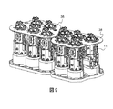
本発明の好適な実施形態において、伝導放射装置はOMUXの全てのフィルターに連結された、単独の伝導放射板38を備えるが、しかし特に図9に表わされているような、実質的に異なる長さのフィルターを備えるOMUXへの適用の場合、OMUXの少なくとも2つのフィルターの第1組と第2組にそれぞれ連結された、幾つかの伝導放射板を備える伝導放射装置を用いることもまた可能である。OMUXが幾つかの伝導放射板38を備えるとき、各種の板が相互に熱的に連結され得るか、又はそれらが独立であり得る。
In a preferred embodiment of the present invention, the conduction radiation device comprises a single
本発明は特定の実施形態に関連して説明されているが、決してそれに限定されず、記述された手段の全ての技術的に等価なものと同様に、それらの組合せが本発明の枠組み内に入る場合、後者も含むことは非常に明白である。 Although the invention has been described in connection with specific embodiments, it is in no way limited thereto, as are all technical equivalents of the means described, combinations thereof being within the framework of the invention. When entering, it is very obvious to include the latter.
1 信号反復装置
2 人工衛星
3 受信アンテナ
4 受信機
5 受信フィルター
6 増幅器
7 伝送フィルター
8 送信アンテナ
9 逆多重化装置
10 出力多重化装置
11 フィルター
12 支持体
13 信号入力
14 信号出力
15 共通の出力ポート
16 横断導波管
17 固定ブラケット
30 外側の周囲壁
31 下端部
32 台座
33 上端部
34 カバー
35 内部空洞
36 内部空洞
37 ―
38 伝導放射装置
39 くり抜き
40 外部の環状カラー
41 伝導放射装置
42 伝導放射装置
43 伝導放射装置
44 温度補償装置
DESCRIPTION OF
38
Claims (13)
Applications Claiming Priority (2)
| Application Number | Priority Date | Filing Date | Title |
|---|---|---|---|
| FR0904212A FR2949923B1 (en) | 2009-09-04 | 2009-09-04 | THERMALLY OPTIMIZED HYPERFREQUENCY CHANNEL MULTIPLEXING DEVICE AND SIGNAL REPEATING DEVICE COMPRISING AT LEAST ONE SUCH MULTIPLEXING DEVICE. |
| FR0904212 | 2009-09-04 |
Publications (2)
| Publication Number | Publication Date |
|---|---|
| JP2011061779A JP2011061779A (en) | 2011-03-24 |
| JP5678317B2 true JP5678317B2 (en) | 2015-03-04 |
Family
ID=42124291
Family Applications (1)
| Application Number | Title | Priority Date | Filing Date |
|---|---|---|---|
| JP2010195547A Expired - Fee Related JP5678317B2 (en) | 2009-09-04 | 2010-09-01 | Thermally optimized microwave channel multiplexer and signal repeater comprising at least one such multiplexer |
Country Status (8)
| Country | Link |
|---|---|
| US (1) | US8340594B2 (en) |
| EP (1) | EP2325939B1 (en) |
| JP (1) | JP5678317B2 (en) |
| CN (1) | CN102013915B (en) |
| CA (1) | CA2714127C (en) |
| ES (1) | ES2393250T3 (en) |
| FR (1) | FR2949923B1 (en) |
| RU (1) | RU2533668C2 (en) |
Families Citing this family (4)
| Publication number | Priority date | Publication date | Assignee | Title |
|---|---|---|---|---|
| DE102012011765B4 (en) | 2012-06-15 | 2016-05-19 | Tesat-Spacecom Gmbh & Co. Kg | Waveguide busbar |
| US9490766B2 (en) * | 2014-02-13 | 2016-11-08 | Ut-Battelle, Llc | Shielded multi-stage EMI noise filter |
| CN106989426A (en) * | 2017-05-23 | 2017-07-28 | 杨金钢 | A kind of low-temperature flue gas heat recovery heat exchange device based on low-grade fever Manifold technology |
| CN109557617B (en) * | 2018-12-25 | 2021-07-16 | 珠海光库科技股份有限公司 | Tunable filter |
Family Cites Families (4)
| Publication number | Priority date | Publication date | Assignee | Title |
|---|---|---|---|---|
| DE4319886C1 (en) * | 1993-06-16 | 1994-07-28 | Ant Nachrichtentech | Arrangement for compensating temperature-dependent changes in volume of a waveguide |
| US20040124954A1 (en) * | 2002-12-30 | 2004-07-01 | Strohecker Michael Robert | Composite microwave multiplexer with low coefficient of thermal expansion and method of manufacture |
| US7564327B2 (en) * | 2006-10-05 | 2009-07-21 | Com Dev International Ltd. | Thermal expansion compensation assemblies |
| RU2342787C1 (en) * | 2007-05-23 | 2008-12-27 | Общество с ограниченной ответственностью "Технологическая лаборатория" | Portable station of satellite communication |
-
2009
- 2009-09-04 FR FR0904212A patent/FR2949923B1/en not_active Expired - Fee Related
-
2010
- 2010-08-06 EP EP10172203A patent/EP2325939B1/en active Active
- 2010-08-06 ES ES10172203T patent/ES2393250T3/en active Active
- 2010-08-18 CN CN201010257808.XA patent/CN102013915B/en active Active
- 2010-08-29 US US12/870,827 patent/US8340594B2/en active Active
- 2010-08-31 CA CA2714127A patent/CA2714127C/en active Active
- 2010-09-01 JP JP2010195547A patent/JP5678317B2/en not_active Expired - Fee Related
- 2010-09-03 RU RU2010136915/07A patent/RU2533668C2/en active
Also Published As
| Publication number | Publication date |
|---|---|
| FR2949923B1 (en) | 2011-08-26 |
| JP2011061779A (en) | 2011-03-24 |
| US8340594B2 (en) | 2012-12-25 |
| RU2010136915A (en) | 2012-03-10 |
| CN102013915B (en) | 2015-05-06 |
| CN102013915A (en) | 2011-04-13 |
| CA2714127A1 (en) | 2011-03-04 |
| FR2949923A1 (en) | 2011-03-11 |
| EP2325939A1 (en) | 2011-05-25 |
| EP2325939B1 (en) | 2012-09-19 |
| US20110058809A1 (en) | 2011-03-10 |
| RU2533668C2 (en) | 2014-11-20 |
| CA2714127C (en) | 2016-09-27 |
| ES2393250T3 (en) | 2012-12-19 |
Similar Documents
| Publication | Publication Date | Title |
|---|---|---|
| JP5678317B2 (en) | Thermally optimized microwave channel multiplexer and signal repeater comprising at least one such multiplexer | |
| KR100995082B1 (en) | Temperature control system of the antenna module | |
| EP2494568B1 (en) | Device for cooling a medium-voltage apparatus using heat pipes under voltage | |
| KR20210033923A (en) | Antenna apparatus | |
| CN105206933B (en) | A kind of radiator structure of active phase array antenna | |
| JP5619069B2 (en) | Active phased array antenna device | |
| US3660784A (en) | Energy absorber and evaporative cooling system | |
| CN104104398A (en) | Transmitting assembly circuit used for rocket-mounted S-frequency-band phased-array antenna and structure thereof | |
| CN109698398B (en) | An integrated design millimeter wave phased array antenna | |
| CN115020956B (en) | Radiating system and method for satellite-borne planar integrated antenna | |
| CN114094304B (en) | A heat dissipation structure of a phased array antenna, a phased array antenna and a satellite platform | |
| US12425053B2 (en) | Wideband modular filter/duplexer system | |
| CN105187023B (en) | A kind of power amplifier device | |
| CN117374554A (en) | Low-orbit satellite phased array antenna thermal control device | |
| CN110775307A (en) | High-flux satellite transponder equipment layout | |
| KR20240140816A (en) | Heat dissipation device, heat dissipation module and antenna apparatus including the same | |
| JP2015524042A (en) | Solar array field and vacuum solar panel | |
| US7864528B2 (en) | Liquid cooled high-frequency filter | |
| US2947956A (en) | Fluid cooled energy transmission control device | |
| KR101473283B1 (en) | Antenna | |
| CN114784500B (en) | Active intelligent antenna | |
| CA3133605C (en) | Arrangement of a waveguide assembly and its manufacturing process | |
| US20250365894A1 (en) | Passive cooling system for radiofrequency components | |
| Federmann et al. | RF Loads for Energy Recovery | |
| CN207925643U (en) | A kind of high-power combiner |
Legal Events
| Date | Code | Title | Description |
|---|---|---|---|
| A621 | Written request for application examination |
Free format text: JAPANESE INTERMEDIATE CODE: A621 Effective date: 20130830 |
|
| A521 | Request for written amendment filed |
Free format text: JAPANESE INTERMEDIATE CODE: A523 Effective date: 20131107 |
|
| A977 | Report on retrieval |
Free format text: JAPANESE INTERMEDIATE CODE: A971007 Effective date: 20140911 |
|
| TRDD | Decision of grant or rejection written | ||
| A01 | Written decision to grant a patent or to grant a registration (utility model) |
Free format text: JAPANESE INTERMEDIATE CODE: A01 Effective date: 20140930 |
|
| A61 | First payment of annual fees (during grant procedure) |
Free format text: JAPANESE INTERMEDIATE CODE: A61 Effective date: 20141008 |
|
| A61 | First payment of annual fees (during grant procedure) |
Free format text: JAPANESE INTERMEDIATE CODE: A61 Effective date: 20141210 |
|
| R150 | Certificate of patent or registration of utility model |
Ref document number: 5678317 Country of ref document: JP Free format text: JAPANESE INTERMEDIATE CODE: R150 |
|
| R250 | Receipt of annual fees |
Free format text: JAPANESE INTERMEDIATE CODE: R250 |
|
| R250 | Receipt of annual fees |
Free format text: JAPANESE INTERMEDIATE CODE: R250 |
|
| R250 | Receipt of annual fees |
Free format text: JAPANESE INTERMEDIATE CODE: R250 |
|
| R250 | Receipt of annual fees |
Free format text: JAPANESE INTERMEDIATE CODE: R250 |
|
| R250 | Receipt of annual fees |
Free format text: JAPANESE INTERMEDIATE CODE: R250 |
|
| R250 | Receipt of annual fees |
Free format text: JAPANESE INTERMEDIATE CODE: R250 |
|
| R250 | Receipt of annual fees |
Free format text: JAPANESE INTERMEDIATE CODE: R250 |
|
| LAPS | Cancellation because of no payment of annual fees |