JP5677757B2 - Ultrasonic diagnostic equipment - Google Patents
Ultrasonic diagnostic equipment Download PDFInfo
- Publication number
- JP5677757B2 JP5677757B2 JP2010058891A JP2010058891A JP5677757B2 JP 5677757 B2 JP5677757 B2 JP 5677757B2 JP 2010058891 A JP2010058891 A JP 2010058891A JP 2010058891 A JP2010058891 A JP 2010058891A JP 5677757 B2 JP5677757 B2 JP 5677757B2
- Authority
- JP
- Japan
- Prior art keywords
- elasticity
- data
- unit
- physical quantity
- scanning
- Prior art date
- Legal status (The legal status is an assumption and is not a legal conclusion. Google has not performed a legal analysis and makes no representation as to the accuracy of the status listed.)
- Active
Links
- 238000011156 evaluation Methods 0.000 claims description 106
- 238000004364 calculation method Methods 0.000 claims description 62
- 239000000523 sample Substances 0.000 claims description 60
- 238000012935 Averaging Methods 0.000 claims description 20
- 238000002604 ultrasonography Methods 0.000 claims description 16
- 238000003745 diagnosis Methods 0.000 claims 1
- 238000012545 processing Methods 0.000 description 53
- 230000005540 biological transmission Effects 0.000 description 32
- 101000864232 Euglena gracilis Delta(8)-fatty-acid desaturase Proteins 0.000 description 24
- 238000012986 modification Methods 0.000 description 21
- 230000004048 modification Effects 0.000 description 21
- 238000010586 diagram Methods 0.000 description 17
- 230000006835 compression Effects 0.000 description 14
- 238000007906 compression Methods 0.000 description 14
- 238000001514 detection method Methods 0.000 description 8
- 230000010349 pulsation Effects 0.000 description 7
- 210000004204 blood vessel Anatomy 0.000 description 5
- 238000006073 displacement reaction Methods 0.000 description 5
- 238000013459 approach Methods 0.000 description 4
- 238000000034 method Methods 0.000 description 4
- 230000006870 function Effects 0.000 description 3
- 230000017531 blood circulation Effects 0.000 description 2
- 239000000463 material Substances 0.000 description 2
- 238000003825 pressing Methods 0.000 description 2
- 230000002040 relaxant effect Effects 0.000 description 2
- 230000002194 synthesizing effect Effects 0.000 description 2
- 239000010936 titanium Substances 0.000 description 2
- 206010028980 Neoplasm Diseases 0.000 description 1
- RTAQQCXQSZGOHL-UHFFFAOYSA-N Titanium Chemical compound [Ti] RTAQQCXQSZGOHL-UHFFFAOYSA-N 0.000 description 1
- 101100218648 Toxoplasma gondii (strain ATCC 50611 / Me49) BFD1 gene Proteins 0.000 description 1
- 239000002253 acid Substances 0.000 description 1
- 210000001715 carotid artery Anatomy 0.000 description 1
- 239000000919 ceramic Substances 0.000 description 1
- 238000002592 echocardiography Methods 0.000 description 1
- 230000000694 effects Effects 0.000 description 1
- 238000002474 experimental method Methods 0.000 description 1
- 230000001681 protective effect Effects 0.000 description 1
- 239000004065 semiconductor Substances 0.000 description 1
- 229910052719 titanium Inorganic materials 0.000 description 1
Images


Classifications
-
- A—HUMAN NECESSITIES
- A61—MEDICAL OR VETERINARY SCIENCE; HYGIENE
- A61B—DIAGNOSIS; SURGERY; IDENTIFICATION
- A61B8/00—Diagnosis using ultrasonic, sonic or infrasonic waves
- A61B8/08—Clinical applications
-
- A—HUMAN NECESSITIES
- A61—MEDICAL OR VETERINARY SCIENCE; HYGIENE
- A61B—DIAGNOSIS; SURGERY; IDENTIFICATION
- A61B8/00—Diagnosis using ultrasonic, sonic or infrasonic waves
- A61B8/13—Tomography
- A61B8/14—Echo-tomography
Landscapes
- Life Sciences & Earth Sciences (AREA)
- Health & Medical Sciences (AREA)
- Biomedical Technology (AREA)
- Biophysics (AREA)
- Nuclear Medicine, Radiotherapy & Molecular Imaging (AREA)
- Pathology (AREA)
- Radiology & Medical Imaging (AREA)
- Engineering & Computer Science (AREA)
- Physics & Mathematics (AREA)
- Heart & Thoracic Surgery (AREA)
- Medical Informatics (AREA)
- Molecular Biology (AREA)
- Surgery (AREA)
- Animal Behavior & Ethology (AREA)
- General Health & Medical Sciences (AREA)
- Public Health (AREA)
- Veterinary Medicine (AREA)
- Ultra Sonic Daignosis Equipment (AREA)
Description
本発明は、超音波診断装置に関し、特に生体組織の硬さ又は軟らかさを表す弾性画像を表示する超音波診断装置に関する。 The present invention relates to an ultrasonic diagnostic apparatus, and more particularly to an ultrasonic diagnostic apparatus that displays an elastic image representing the hardness or softness of a living tissue.
通常のBモード画像と、生体組織の硬さ又は軟らかさを表す弾性画像とを合成して表示させる超音波診断装置が、例えば特許文献1などに開示されている。この種の超音波診断装置において、弾性画像は次のようにして作成される。先ず、生体組織に対し、例えば超音波プローブによる圧迫とその弛緩を繰り返しながら超音波の送受信を行ってエコーを取得する。そして、得られたエコーデータに基づいて、生体組織の弾性に関する物理量を算出し、この物理量を色相情報に変換してカラーの弾性画像を作成する。ちなみに、生体組織の弾性に関する物理量としては、例えば生体組織の歪みなどを算出している。
For example,
ところで、三次元領域における超音波の走査、すなわち超音波振動子の配列方向への超音波の走査と、前記配列方向と直交する方向への超音波の走査とを行なって、三次元データを取得し、この三次元データに基づく超音波画像を表示する場合がある。前記三次元データを取得するための超音波プローブとしては、例えば超音波振動子の配列方向に超音波の走査を行なう電子的走査と、前記配列方向と直交する方向に超音波振動子を移動させて超音波の走査を行なう機械的走査とを組み合わせたメカニカル3Dプローブがある。 By the way, ultrasonic scanning in a three-dimensional region, that is, ultrasonic scanning in the direction of arrangement of the ultrasonic transducers, and ultrasonic scanning in a direction orthogonal to the arrangement direction are performed to obtain three-dimensional data. In some cases, an ultrasonic image based on the three-dimensional data is displayed. As an ultrasonic probe for acquiring the three-dimensional data, for example, an electronic scanning that performs ultrasonic scanning in the arrangement direction of the ultrasonic transducers, and an ultrasonic transducer is moved in a direction orthogonal to the arrangement direction. There is a mechanical 3D probe combined with mechanical scanning that performs ultrasonic scanning.
ここで、本願の発明者は、三次元領域における超音波の走査を行なって得られたエコーデータに基づく弾性画像の表示について鋭意検討したところ、次のような課題を認識するに至った。すなわち、生体組織の物理量の算出は、時間的に異なるフレームに属する同一音線上の二つのエコーデータに基づいて行なっている。従って、同一走査面について少なくとも二フレーム分のスキャンを行なうことが好ましい。しかし、前記メカニカル3Dプローブにおいては、前記超音波振動子の配列方向と直交する方向にこの超音波振動子を移動させながら走査を行なうため、同一走査面について二フレーム分のエコー信号を取得することが困難であり、弾性画像の画質が低下する恐れがある。 Here, the inventor of the present application diligently studied the display of an elastic image based on echo data obtained by performing ultrasonic scanning in a three-dimensional region, and as a result, recognized the following problems. That is, the physical quantity of the living tissue is calculated based on two echo data on the same sound ray belonging to different frames in time. Therefore, it is preferable to scan at least two frames on the same scanning plane. However, since the mechanical 3D probe performs scanning while moving the ultrasonic transducer in a direction orthogonal to the arrangement direction of the ultrasonic transducers, an echo signal for two frames is acquired for the same scanning plane. Is difficult, and the image quality of the elastic image may be lowered.
上述の課題を解決するためになされた第1の観点の発明は、超音波の走査を行なう超音波プローブと、該超音波プローブに三次元領域を走査させる走査制御部であって、一の走査面について複数フレーム分の走査を行なわせる走査制御部と、前記一の走査面における異なるフレームに属する同一音線上のエコーデータに基づいて、生体組織の弾性に関する弾性データを作成する弾性データ作成部と、前記弾性データに基づいて作成された生体組織の弾性画像を表示する表示部と、を備えることを特徴とする超音波診断装置である。 An invention according to a first aspect made to solve the above-described problem is an ultrasonic probe that performs ultrasonic scanning, and a scanning control unit that causes the ultrasonic probe to scan a three-dimensional region, wherein one scanning is performed. A scanning control unit that scans the surface for a plurality of frames, and an elasticity data creation unit that creates elasticity data relating to the elasticity of the living tissue based on echo data on the same sound ray belonging to different frames on the one scanning surface; An ultrasonic diagnostic apparatus comprising: a display unit configured to display an elasticity image of a living tissue created based on the elasticity data.
第2の観点の発明によれば、第1の観点の発明において、前記超音波プローブは、超音波振動子の配列方向へは電子的走査を行ない、前記配列方向と直交する方向へは機械的走査を行なうメカニカル3Dプローブであり、前記走査制御部は、一の走査面で前記機械的走査を停止して、前記配列方向に超音波の走査を行なって複数フレーム分の走査を行なうよう前記超音波プローブを制御することを特徴とする超音波診断装置である。 According to the invention of the second aspect, in the invention of the first aspect, the ultrasonic probe performs electronic scanning in the arrangement direction of the ultrasonic transducers and mechanical in the direction orthogonal to the arrangement direction. The scanning control unit is a mechanical 3D probe that performs scanning, and the scanning control unit stops the mechanical scanning on one scanning plane, and performs scanning for a plurality of frames by performing ultrasonic scanning in the arrangement direction. An ultrasonic diagnostic apparatus that controls an acoustic probe.
第3の観点の発明は、第1の観点の発明において、前記超音波プローブは、超音波振動子の配列方向と該配列方向と直交する方向に電子的走査を行なう超音波プローブであり、前記走査制御部は、一の走査面で前記配列方向に超音波の走査を行なって複数フレーム分の走査をさせることを特徴とする超音波診断装置である。 According to a third aspect of the invention, in the first aspect of the invention, the ultrasonic probe is an ultrasonic probe that performs electronic scanning in an arrangement direction of ultrasonic transducers and a direction orthogonal to the arrangement direction. The scanning control unit is an ultrasonic diagnostic apparatus that performs scanning for a plurality of frames by performing ultrasonic scanning in the arrangement direction on one scanning plane.
第4の観点の発明は、第1〜3のいずれか一の観点の発明において、前記一の走査面における複数フレームの弾性データの中から、所定の評価指標に基づいて一フレーム選択するフレーム選択部を備えることを特徴とする超音波診断装置である。 The invention according to a fourth aspect is the frame selection according to any one of the first to third aspects, wherein one frame is selected from a plurality of frames of elasticity data on the one scanning plane based on a predetermined evaluation index. An ultrasonic diagnostic apparatus comprising a unit.
第5の観点の発明は、第4の観点の発明において、前記フレーム選択部は、前記評価指標として前記弾性データの一フレームにおけるエラー画素を特定し、エラー画素が最も少ないフレームを選択することを特徴とする超音波診断装置である。 According to a fifth aspect of the invention based on the fourth aspect of the invention, the frame selection unit specifies an error pixel in one frame of the elasticity data as the evaluation index, and selects a frame having the smallest error pixel. This is a characteristic ultrasonic diagnostic apparatus.
第6の観点の発明によれば、第5の観点の発明において、前記弾性データ作成部は、生体組織の弾性に関する物理量を画素毎に算出して前記弾性データを作成し、前記フレーム選択部は、予め設定された範囲外の物理量が算出された画素をエラーとすることを特徴とする超音波診断装置である。 According to the sixth aspect of the invention, in the fifth aspect of the invention, the elasticity data creation unit creates the elasticity data by calculating a physical quantity relating to the elasticity of the living tissue for each pixel, and the frame selection unit comprises: The ultrasonic diagnostic apparatus is characterized in that a pixel for which a physical quantity outside a preset range is calculated is regarded as an error.
第7の観点の発明は、第5の観点の発明において、前記弾性データ作成部は、前記一の走査面における同一音線上の時間的に異なるエコーデータに相関ウィンドウを設定し、該相関ウィンドウ間で相関演算を行なって生体組織の弾性に関する物理量を画素毎に算出して前記弾性データの作成を行なうものであり、前記フレーム選択部は、相関係数が所定以下の画素をエラーとすることを特徴とする超音波診断装置である。 According to a seventh aspect of the invention, in the fifth aspect of the invention, the elasticity data creation unit sets a correlation window for temporally different echo data on the same sound ray on the one scanning plane, and The elasticity data is created by calculating a physical quantity related to the elasticity of the living tissue for each pixel by performing a correlation calculation in the frame selection unit, and the frame selection unit determines that a pixel having a correlation coefficient of a predetermined value or less is an error. This is a characteristic ultrasonic diagnostic apparatus.
第8の観点の発明は、第5の観点の発明において、前記フレーム選択部は、前記超音波プローブで取得されたエコー信号の振幅が所定以下である部分に相当する画素をエラーとすることを特徴とする超音波診断装置である。 In an eighth aspect of the invention according to the fifth aspect of the invention, the frame selection unit sets an error in a pixel corresponding to a portion where an amplitude of an echo signal acquired by the ultrasonic probe is equal to or less than a predetermined value. This is a characteristic ultrasonic diagnostic apparatus.
第9の観点の発明は、第4の観点の発明において、前記弾性データ作成部は、前記一の走査面における同一音線上の時間的に異なるエコーデータに相関ウィンドウを設定し、該相関ウィンドウ間で相関演算を行なって生体組織の各部における弾性に関する物理量を算出して前記弾性データの作成を行なうものであり、前記フレーム選択部は、前記評価指標として、前記相関演算で得られた相関係数の平均をフレーム毎に算出し、該相関係数の平均が最も高いフレームを選択することを特徴とする超音波診断装置である。 According to a ninth aspect of the present invention, in the fourth aspect of the invention, the elastic data creation unit sets correlation windows for temporally different echo data on the same sound ray on the one scanning plane, and The elastic coefficient is created by calculating a physical quantity related to elasticity in each part of the living tissue by performing correlation calculation in the frame selection unit, and the frame selection unit uses the correlation coefficient obtained by the correlation calculation as the evaluation index. Is calculated for each frame, and a frame having the highest average of the correlation coefficients is selected.
第10の観点の発明は、第4の観点の発明において、前記弾性データ作成部は、前記一の走査面における同一音線上の時間的に異なるエコーデータに相関ウィンドウを設定し、該相関ウィンドウ間で相関演算を行なって生体組織の各部における弾性に関する物理量を算出して前記弾性データの作成を行なうものであり、前記フレーム選択部は、前記物理量の平均をフレーム毎に算出する物理量平均部と、該物理量平均部による算出値を、予め設定された前記物理量の平均値と比較する比較部と、を有し、該比較部の比較結果を前記評価指標としてフレームの選択を行なうことを特徴とする超音波診断装置である。 According to a tenth aspect of the present invention, in the fourth aspect of the invention, the elasticity data creation unit sets a correlation window for temporally different echo data on the same sound ray on the one scanning plane, and To calculate the physical quantity related to elasticity in each part of the biological tissue and perform the creation of the elastic data, the frame selection unit, a physical quantity average unit for calculating the average of the physical quantity for each frame, A comparison unit that compares a value calculated by the physical quantity average unit with a preset average value of the physical quantity, and selects a frame using a comparison result of the comparison unit as the evaluation index. This is an ultrasonic diagnostic apparatus.
第11の観点の発明は、第4の観点の発明において、前記弾性データ作成部は、前記一の走査面における同一音線上の時間的に異なるエコーデータに相関ウィンドウを設定し、該相関ウィンドウ間で相関演算を行なって生体組織の各部における弾性に関する物理量を算出して前記弾性データの作成を行なうものであり、前記フレーム選択部は、所定の閾値以上の相関係数の相関演算が行なわれた相関ウィンドウについて得られた物理量の平均をフレーム毎に算出する物理量平均部と、予め設定された物理量の平均値に対する前記物理量平均部による算出値の比を算出する比算出部と、前記相関ウィンドウ間の相関演算における相関係数の平均をフレーム毎に算出する相関係数平均部と、前記比算出部の算出値と、前記相関係数平均部の算出値とを乗算する乗算部と、を有し、該乗算部の乗算結果を評価指標としてフレームの選択を行なうことを特徴とする超音波診断装置である。 According to an eleventh aspect of the present invention, in the fourth aspect of the invention, the elasticity data creation unit sets a correlation window for temporally different echo data on the same sound ray on the one scanning plane, and The elasticity data is created by calculating a physical quantity related to elasticity in each part of the biological tissue by performing correlation calculation in the frame selection unit, and the frame selection unit performs correlation calculation of a correlation coefficient equal to or greater than a predetermined threshold value. Between the correlation window, a physical quantity average unit that calculates an average of physical quantities obtained for the correlation window for each frame, a ratio calculation unit that calculates a ratio of a calculated value by the physical quantity average unit to a preset average value of the physical quantity, and the correlation window Correlation coefficient average part for calculating the average of correlation coefficients in the correlation calculation for each frame, the calculated value of the ratio calculation part, and the calculated value of the correlation coefficient average part Anda multiplying unit for multiplying an ultrasonic diagnostic apparatus characterized by the selection of the frame as an evaluation index a multiplication result of the multiplication unit.
第12の観点の発明は、第4の観点の発明において、前記弾性データ作成部は、前記一の走査面における同一音線上の時間的に異なるエコーデータに相関ウィンドウを設定し、該相関ウィンドウ間で相関演算を行なって生体組織の各部における弾性に関する物理量を正負の符合を伴って算出して前記弾性データの作成を行なうものであり、前記フレーム選択部は、一のフレームにおける前記正負の符合の割合を前記評価指標としてフレームの選択を行なうことを特徴とする超音波診断装置である。 According to a twelfth aspect of the present invention, in the fourth aspect of the invention, the elasticity data creation unit sets a correlation window for temporally different echo data on the same sound ray on the one scanning plane, and The physical data relating to elasticity in each part of the living tissue is calculated with a positive / negative sign to create the elasticity data, and the frame selection unit is configured to calculate the positive / negative sign in one frame. An ultrasonic diagnostic apparatus, wherein a frame is selected using a ratio as the evaluation index.
第13の観点の発明は、第1〜3のいずれか一の観点の発明において、被検体の心拍を検出する心拍検出部と、前記一の走査面について、複数フレームの弾性データの中から、前記心拍検出部で検出された心拍情報に基づいて一フレーム選択するフレーム選択部と、を備えることを特徴とする超音波診断装置である。 The invention according to a thirteenth aspect is the invention according to any one of the first to third aspects, wherein the heartbeat detecting unit for detecting the heartbeat of the subject and the one scanning plane are selected from the elasticity data of a plurality of frames. An ultrasonic diagnostic apparatus comprising: a frame selection unit that selects one frame based on heartbeat information detected by the heartbeat detection unit.
第14の観点の発明は、第4〜13のいずれか一の観点の発明において、前記表示部に表示される前記弾性画像は、前記フレーム選択部によって選択されたフレームの弾性データに基づく弾性画像であることを特徴とする超音波診断装置である。 According to a fourteenth aspect, in the invention according to any one of the fourth to thirteenth aspects, the elasticity image displayed on the display unit is an elasticity image based on elasticity data of a frame selected by the frame selection unit. This is an ultrasonic diagnostic apparatus.
第15の観点の発明は、第4〜13のいずれか一の観点の発明において、前記フレーム選択部によって選択されたフレームの弾性データを記憶する記憶部を備えることを特徴とする超音波診断装置である。 An invention according to a fifteenth aspect is the ultrasonic diagnostic apparatus according to any one of the fourth to thirteenth aspects, further comprising a storage unit that stores elasticity data of the frame selected by the frame selection unit. It is.
第16の観点の発明は、第1〜3のいずれか一の観点の発明において、前記弾性データ作成部は、前記一の走査面について得られた複数フレーム分の弾性データを重み付け加算処理して加算弾性データを作成する加算処理部を有しており、前記表示部に表示される弾性画像は、前記加算弾性データに基づく弾性画像であることを特徴とする超音波診断装置である。 According to a sixteenth aspect, in the invention according to any one of the first to third aspects, the elasticity data creation unit performs weighted addition processing on the elasticity data for a plurality of frames obtained for the one scanning plane. An ultrasonic diagnostic apparatus having an addition processing unit for generating addition elasticity data, wherein the elasticity image displayed on the display unit is an elasticity image based on the addition elasticity data.
第17の観点の発明は、第1〜3のいずれか一の観点の発明において、前弾性データ作成部は、一の走査面について得られた複数フレームの弾性データのうち、一のフレームの弾性データにおけるエラー画素のデータを、他のフレームの弾性データにおける非エラー画素のデータに置換して置換済弾性データを作成する置換済弾性データ作成部を有しており、前記表示に表示される弾性画像は、前記置換済弾性データに基づく弾性画像であることを特徴とする超音波診断装置である。 The invention according to a seventeenth aspect is the invention according to any one of the first to third aspects, wherein the pre-elasticity data creation unit is configured to determine the elasticity of one frame among the elasticity data of a plurality of frames obtained for one scanning plane. It has a replaced elasticity data creation unit for creating replaced elasticity data by replacing the error pixel data in the data with the non-error pixel data in the elasticity data of other frames, and the elasticity displayed on the display The ultrasonic diagnostic apparatus is characterized in that the image is an elasticity image based on the replaced elasticity data.
第18の観点の発明は、第1〜3のいずれか一の観点の発明において、前記一の走査面について得られた前記弾性データについて、所定の評価指標に基づいて、所定の画質の弾性画像が得られる弾性データであるか否かの評価を行なう評価部を備え、前記走査制御部は、前記一の走査面についての弾性データについて、前記評価部によって所定の画質の弾性画像が得られる弾性データであると評価された場合に、前記一の走査面から他の走査面に走査面を切り替えることを特徴とする超音波診断装置である。 According to an eighteenth aspect of the invention, in the invention according to any one of the first to third aspects, an elasticity image having a predetermined image quality is obtained based on a predetermined evaluation index for the elasticity data obtained for the one scanning plane. An evaluation unit that evaluates whether or not the elasticity data is obtained, and the scan control unit is configured to obtain elasticity data of a predetermined image quality by the evaluation unit for the elasticity data of the one scanning plane. An ultrasonic diagnostic apparatus that switches a scan plane from one scan plane to another scan plane when it is evaluated as data.
第19の観点の発明は、第18の観点の発明において、前記評価部は、前記評価指標として前記弾性データの一フレームにおけるエラー画素数に基づいて、所定の画質の弾性画像が得られる弾性データであるか否かの評価を行なうことを特徴とする超音波診断装置である。 According to a nineteenth aspect of the present invention, in the eighteenth aspect of the invention, the evaluation unit is an elastic data for obtaining an elastic image having a predetermined image quality based on the number of error pixels in one frame of the elastic data as the evaluation index. It is an ultrasonic diagnostic apparatus characterized by evaluating whether or not.
第20の観点の発明は、第18の観点の発明において、前記弾性データ作成部は、前記一の走査面における同一音線上の時間的に異なるエコーデータに相関ウィンドウを設定し、該相関ウィンドウ間で相関演算を行なって生体組織の各部における弾性に関する物理量を算出して前記弾性データの作成を行なうものであり、前記評価部は、前記評価指標として、前記相関演算で得られた相関係数の平均をフレーム毎に算出し、該相関係数の平均に基づいて、所定の画質の弾性画像が得られる弾性データであるか否かの評価を行なうことを特徴とする超音波診断装置である。 According to a twentieth aspect of the invention, in the eighteenth aspect of the invention, the elasticity data creation unit sets a correlation window for temporally different echo data on the same sound ray on the one scanning plane, and The elastic data is created by calculating a physical quantity related to elasticity in each part of the living tissue by performing a correlation calculation in the evaluation unit, and the evaluation unit uses the correlation coefficient obtained by the correlation calculation as the evaluation index. An ultrasonic diagnostic apparatus characterized in that an average is calculated for each frame, and based on the average of the correlation coefficient, an evaluation is made as to whether or not the elasticity data is an elastic image having a predetermined image quality.
第21の観点の発明は、第18の観点の発明において、前記弾性データ作成部は、前記一の走査面における同一音線上の時間的に異なるエコーデータに相関ウィンドウを設定し、該相関ウィンドウ間で相関演算を行なって生体組織の各部における弾性に関する物理量を算出して前記弾性データの作成を行なうものであり、前記評価部は、前記物理量の平均をフレーム毎に算出する物理量平均部と、該物理量平均部による算出値を、予め設定された前記物理量の平均値と比較する比較部と、を有し、該比較部の比較結果を評価指標として、所定の画質の弾性画像が得られる弾性データであるか否かの評価を行なうことを特徴とする超音波診断装置である。 According to a twenty-first aspect of the invention, in the eighteenth aspect of the invention, the elasticity data creation unit sets a correlation window for temporally different echo data on the same sound ray on the one scanning plane, and The physical data relating to elasticity in each part of the living tissue is calculated by performing a correlation operation to create the elasticity data, and the evaluation unit includes a physical quantity average unit that calculates the average of the physical quantity for each frame, A comparison unit that compares the calculated value of the physical quantity average unit with a preset average value of the physical quantity, and using the comparison result of the comparison unit as an evaluation index, the elasticity data for obtaining an elastic image of a predetermined image quality It is an ultrasonic diagnostic apparatus characterized by evaluating whether or not.
第22の観点の発明は、第18の観点の発明において、前記弾性データ作成部は、前記一の走査面における同一音線上の時間的に異なるエコーデータに相関ウィンドウを設定し、該相関ウィンドウ間で相関演算を行なって生体組織の各部における弾性に関する物理量を算出して前記弾性データの作成を行なうものであり、前記評価部は、所定の閾値以上の相関係数の相関演算が行なわれた相関ウィンドウについて得られた物理量の平均をフレーム毎に算出する物理量平均部と、予め設定された物理量の平均値に対する前記物理量平均部による算出値の比を算出する比算出部と、前記相関ウィンドウ間の相関演算における相関係数の平均をフレーム毎に算出する相関係数平均部と、前記比算出部の算出値と、前記相関係数平均部の算出値とを乗算する乗算部と、を有し、該乗算部の乗算結果を評価指標として、所定の画質の弾性画像が得られる弾性データであるか否かの評価を行なうことを特徴とする超音波診断装置である。 According to a twenty-second aspect of the invention according to the eighteenth aspect, the elasticity data creation unit sets a correlation window for temporally different echo data on the same sound ray on the one scanning plane, and The elasticity data is created by calculating a physical quantity related to elasticity in each part of the living tissue by performing a correlation calculation in the evaluation unit, and the evaluation unit is a correlation in which a correlation calculation of a correlation coefficient equal to or greater than a predetermined threshold is performed. Between the correlation window, a physical quantity average unit that calculates the average of the physical quantities obtained for the window for each frame, a ratio calculation unit that calculates a ratio of a calculated value by the physical quantity average unit to a preset average value of the physical quantity, and the correlation window Multiplying the correlation coefficient average unit for calculating the average of the correlation coefficient in the correlation calculation for each frame, the calculated value of the ratio calculation unit, and the calculated value of the correlation coefficient average unit An ultrasonic diagnostic apparatus characterized in that evaluation is made as to whether or not elasticity data is obtained by obtaining an elasticity image of a predetermined image quality by using a multiplication result of the multiplication unit as an evaluation index. is there.
第23の観点の発明は、第18の観点の発明において、前記弾性データ作成部は、前記一の走査面における同一音線上の時間的に異なるエコーデータに相関ウィンドウを設定し、該相関ウィンドウ間で相関演算を行なって生体組織の各部における弾性に関する物理量を正負の符合を伴って算出して前記弾性データの作成を行なうものであり、前記評価部は、一のフレームにおける前記正負の符合の割合を前記評価指標として所定の画質の弾性画像が得られる弾性データであるか否かの評価を行なうことを特徴とする超音波診断装置である。 According to a twenty-third aspect of the present invention, in the eighteenth aspect of the invention, the elasticity data creation unit sets a correlation window for temporally different echo data on the same sound ray on the one scanning plane, and The elasticity data is created by calculating a physical quantity related to elasticity in each part of the living tissue with a positive / negative sign by performing a correlation calculation in the above, and the evaluation unit is a ratio of the positive / negative sign in one frame. It is an ultrasonic diagnostic apparatus characterized by evaluating whether or not the elasticity data is an elastic image having a predetermined image quality using the evaluation index as the evaluation index.
第24の観点の発明は、第18の観点の発明において、前記弾性データ作成部は、生体組織の弾性に関する物理量を画素毎に算出して前記弾性データを作成し、前記評価部は、前記弾性データの一フレームにおける画素毎の前記物理量の合計を前記評価指標として所定の画質の弾性画像が得られる弾性データであるか否かの評価を行なうことを特徴とする超音波診断装置である。 According to a twenty-fourth aspect of the present invention, in the eighteenth aspect of the invention, the elasticity data creation unit creates the elasticity data by calculating a physical quantity related to the elasticity of the living tissue for each pixel, and the evaluation unit An ultrasonic diagnostic apparatus that evaluates whether or not elasticity data is obtained by using a total of the physical quantities for each pixel in one frame of data as an evaluation index to obtain an elasticity image of a predetermined image quality.
第25の観点の発明は、第18の観点の発明において、前記弾性データ作成部は、生体組織の弾性に関する物理量を画素毎に算出して前記弾性データを作成し、前記評価部は、前記弾性データの一フレームにおける画素毎の前記物理量の平均を評価指標として、所定の画質の弾性画像が得られる弾性データであるか否かの評価を行なうことを特徴とする超音波診断装置である。 In a twenty-fifth aspect of the invention according to the eighteenth aspect of the invention, the elasticity data creation unit creates the elasticity data by calculating a physical quantity related to the elasticity of the living tissue for each pixel, and the evaluation unit creates the elasticity An ultrasonic diagnostic apparatus characterized in that evaluation is made as to whether or not elastic data is obtained with an elastic image having a predetermined image quality, using an average of the physical quantities for each pixel in one frame of data as an evaluation index.
第26の観点の発明は、第1〜3の観点の発明において、被検体の心拍を検出する心拍検出部を備え、前記走査制御部は、前記心拍検出部で検出された心拍情報に基づいて、前記超音波プローブによって走査を行なう部位に応じて定まるタイミングで前記一の走査面から他の走査面に走査面を切り替えることを特徴とする超音波診断装置である。 An invention of a twenty-sixth aspect is the invention of the first to third aspects, further comprising a heartbeat detection unit that detects a heartbeat of the subject, and the scanning control unit is based on heartbeat information detected by the heartbeat detection unit. The ultrasonic diagnostic apparatus is characterized in that the scanning plane is switched from the one scanning plane to the other scanning plane at a timing determined according to a part to be scanned by the ultrasonic probe.
上記観点の発明によれば、前記走査制御部は、前記超音波プローブによって三次元領域を走査させる時に、一の走査面について複数フレーム分の走査を行なわせる。従って、同一走査面について異なるフレームに属するエコーデータを取得することができ、このようなエコーデータに基づいて、前記物理量が算出されて前記弾性画像データが作成されるので、この弾性画像データに基づく弾性画像の画質を維持することができる。 According to the invention of the above aspect, the scanning control unit performs scanning for a plurality of frames on one scanning plane when scanning the three-dimensional region with the ultrasonic probe. Accordingly, it is possible to acquire echo data belonging to different frames for the same scanning plane, and the physical quantity is calculated and the elastic image data is created based on such echo data. The image quality of the elastic image can be maintained.
また、他の観点の発明によれば、複数フレームの弾性データの中から、前記フレーム選択部によって所定の評価指標や心拍情報に基づいて一フレームの弾性データが選択され、この弾性データに基づく弾性画像が表示されるので、生体組織の弾性をより正確に反映した弾性画像を表示することができる。 According to another aspect of the invention, one frame of elasticity data is selected from a plurality of frames of elasticity data based on a predetermined evaluation index and heart rate information by the frame selection unit, and the elasticity based on the elasticity data is selected. Since the image is displayed, it is possible to display an elasticity image that more accurately reflects the elasticity of the living tissue.
また、他の観点の発明によれば、一の走査面における複数フレーム分の弾性データを重み付け加算処理して加算弾性データが作成され、この加算弾性データに基づく弾性画像が表示されるので、生体組織の弾性をより正確に反映した弾性画像を表示することができる。 According to another aspect of the invention, the elasticity data for a plurality of frames on one scanning plane is weighted and added to create addition elasticity data, and an elasticity image based on the addition elasticity data is displayed. An elastic image that more accurately reflects the elasticity of the tissue can be displayed.
また、他の観点の発明によれば、エラー画素のデータが非エラー画素の歪みデータに置換されて置換済物理量フレームデータが作成され、この置換済物理量フレームデータに基づく弾性画像が表示されるので、生体組織の弾性をより正確に反映した弾性画像を表示することができる。 Further, according to another aspect of the invention, error pixel data is replaced with non-error pixel distortion data to create replaced physical quantity frame data, and an elastic image based on the replaced physical quantity frame data is displayed. The elasticity image reflecting the elasticity of the living tissue more accurately can be displayed.
また、他の観点の発明によれば、前記評価部によって所定の画質の弾性画像が得られる弾性データであると評価された場合に、前記一の走査面から他の走査面に走査面が切り替えられるので、生体組織の弾性をより正確に反映した弾性画像を得ることができる弾性データを各走査面について取得することができる。 According to another aspect of the invention, when the evaluation unit evaluates the elasticity data to obtain an elastic image having a predetermined image quality, the scanning plane is switched from the one scanning plane to the other scanning plane. Therefore, elasticity data that can obtain an elasticity image reflecting the elasticity of the living tissue more accurately can be acquired for each scanning plane.
また、他の観点の発明によれば、心拍情報が参照されて前記一の走査面から他の走査面に走査面が切り替えられるので、生体組織の弾性をより正確に反映した弾性画像を得ることができる弾性データを各走査面について取得することができる。 According to another aspect of the invention, since the scanning plane is switched from the one scanning plane to the other scanning plane with reference to the heartbeat information, an elasticity image that more accurately reflects the elasticity of the living tissue is obtained. The elasticity data that can be obtained can be acquired for each scanning plane.
以下、本発明の実施形態について図面に基づいて詳細に説明する。
(第一実施形態)
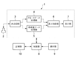
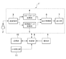
先ず、第一実施形態について図1〜図9に基づいて説明する。図1に示す超音波診断装置1は、超音波プローブ2、送受信部3、Bモードデータ処理部4、物理量データ処理部5、表示制御部6、表示部7、制御部8、操作部9及び記憶部10を備える。
Hereinafter, embodiments of the present invention will be described in detail with reference to the drawings.
(First embodiment)
First, a first embodiment will be described with reference to FIGS. 1 includes an
前記超音波プローブ2は、生体組織に対して超音波を送信しそのエコーを受信する。前記超音波プローブ2は、本発明における超音波プローブの実施の形態の一例である。この超音波プローブ2を生体組織の表面に当接させた状態で圧迫と弛緩を繰り返すなどしながら超音波の送受信を行なって取得されたエコーデータに基づいて、後述のように弾性画像が作成される。
The
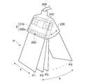
前記超音波プローブ2の概略構成について図2に基づいて説明する。前記超音波プローブ2は、メカニカル3Dプローブであり、振動子アレイ200、ダンパー210、モーター220を有し、これらを保護ケース230に収容することにより構成されている。前記振動子アレイ200は、例えばPZT(チタン(Ti)酸ジルコン(Zr)酸鉛)セラミックス等の圧電材料によって形成される複数の振動子200aが、第一方向aに沿って配列されることにより構成されている。かかる振動子アレイ200の一部の振動子200aを複数駆動することにより、超音波ビームが送信されるようになっている。そして、駆動する振動子200aを順次切り換えることにより、第一方向aに電子的走査を行い、一の走査面Pが形成されるようになっている。
A schematic configuration of the
前記ダンパー210は、前記振動子アレイ200を駆動させて超音波ビームを被検体に送信した後に、前記振動子アレイ200の自由振動を抑制するものである。また、前記ダンパー210は、吸音効果を有する材料を用いて構成され、前記ダンパー210から後方のプローブケーブル300との接続側への超音波の不必要な伝搬を抑制するようになっている。
The
前記モーター220は、前記振動子アレイ200を、機械的に前記振動子200aの配列方向(前記第一方向a)と直交する第二方向bに移動させる。これにより、第二方向bにおいて、複数の走査面P1,P2,P3,・・・,PX(Xはn番目の走査面であることを示す)を形成することができ、三次元領域の走査を行なうことができるようになっている。
The
前記送受信部3は、前記制御部8からの制御信号に基づいて前記超音波プローブ2を所定の走査条件で駆動させて音線毎の超音波の走査を行なう。本例では、前記送受信部3は、前記超音波プローブ2に、第一方向aへの電子的走査を行なわせ、また前記モーター220を駆動させて第二方向bへの機械的走査を行なわせる。詳細は後述する。前記送受信部3及び前記制御部8は、本発明における走査制御部の実施の形態の一例である。
The transmission /
また、送受信部3は、前記超音波プローブ2で受信したエコーについて、整相加算処理等の信号処理を行なう。前記送受信部3で信号処理されたエコーデータは、前記Bモードデータ処理部4及び前記物理量データ処理部5に出力される。
The transmission /
前記Bモードデータ処理部4は、前記送受信部3から出力されたエコーデータに対し、対数圧縮処理、包絡線検波処理等のBモード処理を行い、Bモードデータを作成する。一フレーム分のBモードデータをBモードフレームデータBFDとする。このBモードフレームデータBFDは、前記Bモードデータ処理部4から前記表示制御部6へ出力される。
The B-mode
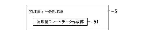
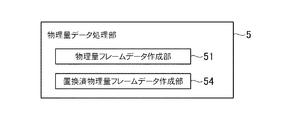
前記物理量データ処理部5は、図3に示すように物理量フレームデータ作成部51を有している。この物理量フレームデータ作成部51は、前記送受信部3から出力されたエコーデータに基づいて、生体組織における各部の弾性に関する物理量のデータからなる物理量フレームデータEFDを作成する。前記物理量データ処理部5は、例えば特開2008−126079号公報に記載されているように、一の走査面Pn(n:自然数)における同一音線上の時間的に異なるエコーデータに相関ウィンドウを設定し、この相関ウィンドウ間で相関演算を行なって前記弾性に関する物理量を算出し前記物理量フレームデータEFDを作成する。詳細は後述する。
The physical quantity
前記物理量フレームデータEFDは、弾性画像の作成に用いられるデータであり、本発明における弾性データの実施の形態の一例である。ちなみに、本発明において弾性データとは、弾性画像の作成に用いられるデータを云う。前記物理量データ処理部5は、本発明における弾性データ作成部の実施の形態の一例である。
The physical quantity frame data EFD is data used to create an elasticity image, and is an example of an embodiment of elasticity data in the present invention. Incidentally, the elasticity data in the present invention refers to data used for creating an elasticity image. The physical quantity
前記表示制御部6には、前記Bモードデータ処理部4からのBモードフレームデータBFD及び前記物理量データ処理部5からの物理量フレームデータEFDが入力されるようになっている。前記表示制御部6は、図4に示すようにメモリ61、Bモード画像データ作成部62、弾性画像データ作成部63、表示画像制御部64を有している。
The
前記メモリ61には、前記BモードフレームデータBFD及び前記物理量フレームデータEFDが記憶される。前記BモードフレームデータBFD及び前記物理量フレームデータEFDは、音線毎のデータとして前記メモリ61に記憶される。そして、このメモリ61には、三次元の走査領域における複数の走査面PnのBモードフレームデータBFD及び前記物理量フレームデータEFDが記憶される。
The
前記メモリ61は、RAM(Random Access Memory)やROM(Read Only Memory)などの半導体メモリで構成されている。ちなみに、前記BモードフレームデータBFD及び前記物理量フレームデータEFDは、HDD(Hard Disk Drive)などで構成される前記記憶部10にも記憶されるようになっていてもよい。前記メモリ61及び前記記憶部10は、本発明における記憶部の実施の形態の一例である。
The
ここで、前記超音波プローブ2で得られたエコーデータであって、後述のBモード画像データ及びカラー弾性画像データに変換される前のデータをローデータ(Raw Data)と云うものとする。前記メモリ61に記憶されるBモードフレームデータBFD及び物理量フレームデータEFDは、ローデータである。
Here, the echo data obtained by the
前記Bモード画像データ作成部62は、前記BモードフレームデータBFDを、エコーの信号強度に応じた輝度情報を有するBモード画像データBGDに変換する。また、前記弾性画像データ作成部63は、前記物理量フレームデータEFDを変位に応じた色相情報を有するカラー弾性画像データEGDに変換する。ちなみに、前記Bモード画像データBGDにおける輝度情報及び前記カラー弾性画像データEGDにおける色相情報は所定の階調(例えば256階調)からなる。
The B-mode image
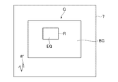
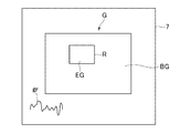
前記表示画像制御部63は、前記Bモード画像データBGD及び前記カラー弾性画像データEGDを加算処理することによって合成し、前記表示部7に表示する二次元の超音波画像の画像データを作成する。この画像データは、図5に示すように白黒のBモード画像BGとカラーの弾性画像EGとが合成された二次元の超音波画像Gとして前記表示部7に表示される。本例では、前記弾性画像EGは、関心領域R内に半透明で(背景のBモード画像が透けた状態で)表示される。前記表示部7は、本発明における表示部の実施の形態の一例である。また、前記関心領域Rは、生体組織の弾性画像が作成される領域(弾性画像作成領域)である。
The display
また、前記表示画像制御部63は、特に図示しないが各走査面Pnについての前記BモードデータBFD及び前記物理量フレームデータEFDに基づいて、三次元のBモード画像及び三次元の弾性画像とを作成し、これらを合成して得られた三次元画像を前記表示部7に表示する(例えば、特開2008−259605)。或いは、前記表示画像制御部63は、各走査面Pnについての前記物理量フレームデータEFDに基づいて、三次元の弾性画像のみを作成して前記表示部7に表示してもよい。ちなみに、本例においては、三次元画像の表示モード(前記三次元画像を表示する場合と三次元の弾性画像を表示する場合のモード)と二次元画像の表示モードとを有し、両者は別々に表示される。
The display
前記制御部8は、CPU(Central Processing Unit)で構成され、前記記憶部10に記憶された制御プログラムを読み出し、前記超音波診断装置1の各部における機能を実行させる。また、前記操作部9は、操作者が指示や情報を入力するためのキーボード及びポインティングデバイス(図示省略)などを含んで構成されている。
The
さて、本例の超音波診断装置1の作用について説明する。前記送受信部3は、前記超音波プローブ2から被検体の生体組織へ超音波を送信させ、そのエコーデータを取得する。この時、前記超音波プローブ2により、例えば被検体への圧迫とその弛緩を繰り返しながら超音波の送受信を行う。
Now, the operation of the ultrasonic
前記送受信部3は、一の走査面Pn(ここでは、1≦n≦X−1)において前記振動子アレイ200を静止させた状態で、前記一の走査面Pnについて予め設定された複数フレーム分の走査を行なわせる。そして、前記送受信部3は、一の走査面Pnについて複数フレーム分の走査を行なわせた後、次の走査面P(n+1)まで前記振動子アレイ200を移動させた後に停止し、その走査面P(n+1)において再び複数フレーム分の走査を行なわせる。
The transmission /
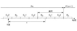
前記送受信部3は、Bモード画像を作成するためのBモード画像用走査と、弾性画像を作成するための弾性画像用走査とを別に行なう。弾性画像用走査としては、被検体における弾性画像を作成する領域(弾性画像作成領域)において、同一音線上に二回の走査を行なう。従って、前記送受信部3は、一の走査面Pnについて、図6に示すように少なくとも一フレーム分のBモード画像用走査BSを行ない、また二フレーム分の弾性画像用走査ES1,ES2を行なう。
The transmission /
ちなみに、Bモード画像用走査は、Bモード画像の作成に適したスキャンパラメータでの超音波の走査であり、また弾性画像用走査は、弾性画像の作成に適したスキャンパラメータでの超音波の走査である。 Incidentally, the B-mode image scan is an ultrasonic scan with a scan parameter suitable for creating a B-mode image, and the elastic image scan is an ultrasonic scan with a scan parameter suitable for creating an elastic image. It is.
一フレーム分のBモード画像用走査BSと、二フレーム分の弾性画像用走査ES1,ES2とから得られるデータにより、一フレーム分の超音波画像Gが得られる。以下、詳しく説明する。 And scanning B S one frame of B-mode image, the data obtained from the two-frame portion of the elastic image scanning E S 1, E S 2 Prefecture, one frame of ultrasonic image G can be obtained. This will be described in detail below.
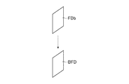
前記Bモード画像用走査BSによって得られたエコーに対して前記送受信部3において信号処理して得られた一フレーム分のエコーデータを、フレームデータFDbとする。前記Bモードデータ処理部4は、前記送受信部3から出力されたフレームデータFDbに基づいて、図7に示すようにBモードフレームデータBFDを作成する。
One frame of the echo data obtained by the signal processing at the transmitting and receiving
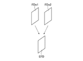
また、前記弾性画像用走査ES1によって得られたエコーに対して前記送受信部3において信号処理して得られた一フレーム分のエコーデータを、フレームデータFDe1とし、前記弾性画像用走査ES2によって得られたエコーに対して前記送受信部3において信号処理して得られた一フレーム分のエコーデータを、フレームデータFDe2とする。前記物理量フレームデータ作成部51は、図8に示すように前記送受信部3から出力されたフレームデータFDe1,FDe2に基づいて、物理量フレームデータEFDを作成する。
Further, echo data for one frame obtained by performing signal processing in the transmission /
前記物理量フレームデータEFDの作成についてもう少し詳しく説明すると、前記物理量フレームデータ作成部51は、生体組織における各部の弾性に関する物理量として、前記超音波プローブ2による圧迫とその弛緩などによって生じた生体組織の変形による各部の歪みSを算出する。前記物理量フレームデータ作成部5は、前記フレームデータFDe1及び前記フレームデータFDe2における同一音線上の二つのエコーデータに基づいて歪みSを算出する。
The creation of the physical quantity frame data EFD will be described in more detail. The physical quantity frame
より詳細には、前記物理量フレームデータ作成部51は、前記フレームデータFDe1,FDe2に属するエコーデータのそれぞれに相関ウィンドウを設定する。具体的には、前記弾性データ作成部5は、図9に示すように前記フレームデータFDe1に属するエコーデータに相関ウィンドウW1を設定し、前記フレームデータFDe2に属するエコーデータに相関ウィンドウW2を設定する。そして、前記物理量フレームデータ作成部51は、前記相関ウィンドウW1,W2間で相関演算を行なって歪みSを算出する。一対の前記相関ウィンドウW1,W2からは一画素分の歪みSのデータが得られ、この歪みSのデータを一フレーム分作成することにより、生体組織における各部の歪みSのデータからなる物理量フレームデータが得られる。
More specifically, the physical quantity frame
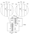
さらに具体的に説明すると、図9において、前記フレームデータFDe1,FDe2は、複数本の音線上において取得されたエコーデータからなる。図9では、前記フレームデータFDe1における複数本の音線の一部として、五本の音線L1a,L1b,L1c,L1d,L1eが示され、また前記フレームデータFDe2において前記音線L1a〜L1eに対応する音線として、音線L2a,L2b,L2c,L2d,L2eが示されている。すなわち、前記音線L1a及び前記音線L2a、前記音線L1b及び前記音線L2b、前記音線L1c及び前記音線L2c、前記音線L1d及び前記音線L2d、前記音線L1e及び前記音線L2eは、異なる二つのフレームに属する同一音線に該当する。また、図9においてR(i),R(ii)は、前記関心領域Rに対応する領域を示している。 More specifically, in FIG. 9, the frame data FDe1 and FDe2 are made of echo data acquired on a plurality of sound rays. In FIG. 9, five sound lines L1a, L1b, L1c, L1d, and L1e are shown as part of a plurality of sound lines in the frame data FDe1, and the sound lines L1a to L1e are shown in the frame data FDe2. As corresponding sound rays, sound rays L2a, L2b, L2c, L2d, and L2e are shown. That is, the sound ray L1a and the sound ray L2a, the sound ray L1b and the sound ray L2b, the sound ray L1c and the sound ray L2c, the sound ray L1d and the sound ray L2d, the sound ray L1e and the sound ray. L2e corresponds to the same sound ray belonging to two different frames. In FIG. 9, R (i) and R (ii) indicate regions corresponding to the region of interest R.
例えば、前記音線L1c上のエコーデータに、前記相関ウィンドウW1として相関ウィンドウW1cが設定され、前記音線L2c上のエコーデータに、前記相関ウィンドウW2として相関ウィンドウW2cが設定されたとする。前記物理量フレームデータ作成部51は、前記相関ウィンドウW1c,W2c間で相関演算を行ない、歪みSを算出する。前記弾性データ作成部5は、前記音線L1c,L2c上において、前記領域R(i),R(ii)の上端100から下端101まで相関ウィンドウW1c,W2cを順次設定し、歪みSを算出する。また、前記物理量フレームデータ作成部51は、前記領域R(i),R(ii)内の他の音線についても同様にして歪みSを算出する。これにより、歪みSのデータからなる一フレーム分の物理量フレームデータEFDが得られる。
For example, it is assumed that a correlation window W1c is set as the correlation window W1 in the echo data on the sound ray L1c, and a correlation window W2c is set as the correlation window W2 in the echo data on the sound ray L2c. The physical quantity frame
前記BモードフレームデータBFD及び前記物理量フレームデータEFDは、前記メモリ61に記憶される。そして、前記BモードフレームデータBFDに基づいて作成されるBモード画像データBGDと、前記物理量フレームデータEFDに基づいて作成されるカラー弾性画像データEGDとが合成され、Bモード画像BGと弾性画像EGとが合成された二次元の超音波画像Gが前記表示部7に表示される。
The B-mode frame data BFD and the physical quantity frame data EFD are stored in the
また、前記表示部7には、三次元のBモード画像及び三次元の弾性画像を合成して得られた三次元画像や、三次元の弾性画像が表示されてもよい。
The
本例の超音波診断装置1によれば、前記振動子アレイ200が一の走査面Pnにおいて静止した状態で複数フレーム分の走査が行なわれ、各走査面Pについて複数のフレームデータFDe1,FDe2が得られる。従って、これらフレームデータFDe1,FDe2に基づいて前記物理量フレームデータBFDを作成することができるので、弾性画像EGの画質を維持することができる。
According to the ultrasonic
(第二実施形態)
次に、第二実施形態について説明する。なお、以下の説明では、第一実施形態と異なる事項について説明する。
(Second embodiment)
Next, a second embodiment will be described. In the following description, items different from the first embodiment will be described.
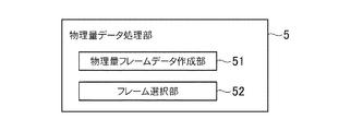
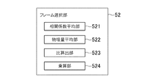
本例においては、図10に示すように、前記物理量データ処理部5は、前記物理量フレームデータ作成部51のほか、フレーム選択部52を有している。このフレーム選択部52は、一の走査面Pnにおける複数フレームの物理量フレームデータEFDの中から、所定の評価指標に基づいて、生体組織の弾性を最も正確に反映した画質の弾性画像が得られる物理量フレームデータEFDを一フレーム選択するようになっている。詳細は後述する。
In this example, as shown in FIG. 10, the physical quantity
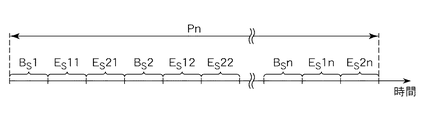
本例の作用について説明する。本例において、前記送受信部3は、一の走査面Pnにおいて前記振動子アレイ200を静止させた状態で、前記一の走査面Pnについて複数フレーム分(nフレーム分)の超音波画像Gが得られるように走査を行なわせる。すなわち、本例では、前記送受信部3は、一の走査面Pnにおいて、図11に示すように、一フレーム分のBモード画像用走査BSと二フレーム分の弾性画像用走査ES1,ES2を一セットの走査として、これを複数セット(nセット)分行なわせる。すなわち、Bモード画像用走査BS1、弾性画像用走査ES11,ES21、Bモード画像用走査BS2、弾性画像用走査ES12,ES22、・・・、Bモード画像用走査BSn、弾性画像用走査ES1n,ES2nを行なわせる。
The operation of this example will be described. In this example, the transmission /
ここで、一の走査面Pnについてのフレーム数nを、操作者が前記操作部9において設定できるようになっていてもよい。ここでのフレーム数とは、例えば超音波画像Gのフレーム数である。従って、実際の走査は、設定されたフレーム数の三倍のフレーム数分行なわれる。
Here, the operator may be able to set the number of frames n for one scanning plane Pn in the
また、フレーム数ではなく、一の走査面Pnについて走査を行なう時間の長さを設定してもよい。ただし、設定される時間の長さは、一の走査面Pnにおいて複数フレーム分の弾性画像EGが得られる長さである。 Further, not the number of frames but the length of time for scanning for one scanning plane Pn may be set. However, the length of time to be set is a length at which an elastic image EG for a plurality of frames is obtained on one scanning plane Pn.
前記弾性画像用走査ES11によって得られたエコーに対して前記送受信部3において信号処理して得られた一フレーム分のデータをフレームデータFDe11、前記弾性画像用走査ES21によって得られたエコーに対して前記送受信部3において信号処理して得られた一フレーム分のデータをフレームデータFDe21、前記弾性画像用走査ES12によって得られたエコーに対して前記送受信部3において信号処理して得られた一フレーム分のデータをフレームデータFDe12、前記弾性画像用走査ES22によって得られたエコーに対して前記送受信部3において信号処理して得られた一フレーム分のデータをフレームデータFDe22とする。また、前記弾性画像用走査ES1nによって得られたエコーに対して前記送受信部3において信号処理して得られた一フレーム分のデータをフレームデータFDe1n、前記弾性画像用走査ES2nによって得られたエコーに対して前記送受信部3において信号処理して得られた一フレーム分のデータをフレームデータFDe2nとする。
Data for one frame obtained by performing signal processing in the transmission /
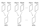
前記物理量フレームデータ作成部51は、図12に示すように前記フレームデータFDe11,FDe21に基づいて物理量フレームデータEFD1を作成し、前記フレームデータFDe12,FDe22に基づいて物理量フレームデータEFD2を作成する。また、前記フレームデータFDe1n,FDe2nに基づいて物理量フレームデータEFDnを作成する。
As shown in FIG. 12, the physical quantity frame
前記フレーム選択部52は、前記物理量フレームデータEFD1,EFD2,・・・,EFDnの中から、所定の評価指標に基づいて一フレーム選択し、選択したフレームを前記表示制御部6へ出力する。
The
ここで、前記所定の評価指標について説明する。この評価指標は、生体組織の弾性をより正確に反映した弾性画像を得ることができるか否かという観点からの評価指標である。本例では、前記フレーム選択部52は、前記評価指標として、先ず前記各物理量フレームデータEFD1〜EFDnにおけるエラー画素数を算出する。そして、前記フレーム選択部52は、エラー画素数が最も少ない物理量フレームデータを選択する。これにより、前記物理量フレームデータEFD1〜EFDnの中で、生体組織の弾性を最も正確に反映した弾性画像を得ることができる物理量フレームデータEFDが選択されることになる。
Here, the predetermined evaluation index will be described. This evaluation index is an evaluation index from the viewpoint of whether or not an elasticity image reflecting the elasticity of a living tissue can be obtained more accurately. In this example, the
本例では、前記フレーム選択部52は、各画素毎の歪みSについてエラーか否かを判定し、エラー画素を特定する。具体的には、前記フレーム選択部52は、各画素の歪みSが、予め設定された所定の範囲外になっている場合、すなわち歪みSが、m≦S≦nを満たさない場合に、エラーと判定する。前記所定の範囲(m及びn)は、例えば生体組織の弾性を考慮して通常考えられる歪み値の範囲に設定されるものであり、著しく逸脱した歪み値をエラーとするような値に設定される。或いは、前記所定の範囲は、一フレームにおける歪みSの平均値を算出し、この平均値に基づいて設定してもよい。m≦S≦nであれば、所定の画質の弾性画像EGを得ることができる。
In this example, the
ここで、前記フレーム選択部52は、前記物理量フレームデータにおける歪みSが、所定の歪み値STH以下になっている画素をエラーとしてもよい。言い換えれば、前記フレーム選択部52は、所定の前記超音波プローブ2で取得されたエコー信号の振幅が所定以下である部分に相当する画素をエラーとしてもよい。
Here, the
ちなみに、例えば、前記超音波プローブ2から送信された超音波の反射が無いか、或いは反射が少ない場合のエコー信号は、歪みSを適切に算出できる信号ではなく、所定の画質の弾性画像EGを得ることができるものではない。従って、所定の歪み値STHは、エコー信号の振幅がほとんど無いようなエコー信号に基づいて算出された比較的低い歪み値に設定される。
Incidentally, for example, the echo signal when there is no reflection or little reflection of the ultrasonic wave transmitted from the
また、前記フレーム選択部52は、画素毎の相関演算で得られた相関係数Cについてエラーか否かを判定してもよい。具体的には、前記フレーム選択部52は、前記相関ウィンドウW1,W2間の相関演算で得られた相関係数Cが所定の閾値CTH以下の画素をエラーとする。ここでは、前記相関係数Cは、0≦C≦1であるため、前記閾値CTHは0≦CTH≦1の範囲で設定される。ここで、相関係数Cが1に近いほど、生体組織の弾性を正確に反映した歪みSが得られる。前記閾値CTHは、生体組織の弾性をある程度正確に反映した歪みSが算出される相関演算で得られる相関係数の値に設定される。言い換えれば、前記閾値CTHを超える相関係数の相関演算によって歪みSが算出されれば、所定の画質の弾性画像EGが得られる
Further, the
前記フレーム選択部52は、物理量フレームデータEFDの選択を行なうと、この物理量フレームデータEFDと互いに対になるBモードフレームデータBFDを選択する。ここで、互いに対になるBモードフレームデータBFD及び物理量フレームデータEFDとは、一セットのBモード画像用走査BSと弾性画像用走査ES1,ES2で得られたフレームデータに基づくデータである。
When selecting the physical quantity frame data EFD, the
前記フレーム選択部52によって選択された前記BモードフレームデータBFD及び前記物理量フレームデータEFDは、前記メモリ61に記憶され、前記物理量フレームデータEFDに基づいて作成されたカラー弾性画像データEGDが、前記BモードフレームデータBFDに基づいて作成されたBモード画像データBGDと合成されて前記超音波画像Gが前記表示部7に表示される。
The B-mode frame data BFD and the physical quantity frame data EFD selected by the
また、前記メモリ61には、前記フレーム選択部52によって選択された前記BモードフレームデータBFD及び前記物理量フレームデータEFDが、各走査面Pについて記憶される。そして、本例では、各走査面Pについての前記Bモードフレームデータ及び前記物理量フレームデータEFDに基づいて前記三次元画像や三次元の弾性画像が作成され表示される。
The
本例によれば、前記フレーム選択部52によって選択された物理量フレームデータEFDに基づく弾性画像EGや、前記三次元画像又は三次元の弾性画像が表示されるので、生体組織の弾性をより正確に反映した画像を表示することができる。
According to this example, the elasticity image EG based on the physical quantity frame data EFD selected by the
なお、上述の説明では、前記物理量フレームデータEFDについての選択を行なうようになっているが、前記カラー弾性画像データEGDについての選択を行うようになっていてもよい。この場合には、前記カラー弾性画像データが、本発明における弾性データの実施の形態の一例である。 In the above description, the physical quantity frame data EFD is selected. However, the color elastic image data EGD may be selected. In this case, the color elasticity image data is an example of an embodiment of elasticity data in the present invention.
次に、第二実施形態の変形例について説明する。以下の変形例では、前記実施形態と異なる事項について説明する。 Next, a modification of the second embodiment will be described. In the following modification, matters different from the above-described embodiment will be described.
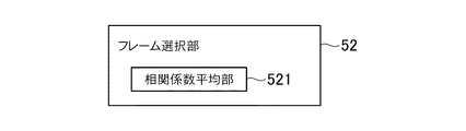
先ず、第一変形例について説明する。この第一変形例では、前記フレーム選択部52は、図13に示すように相関係数平均部521を有する。この相関係数平均部521は、前記評価指標として、前記各物理量フレームデータEFD1〜EFDnを作成した時の各画素毎の相関演算における相関係数Cの平均値CAVをフレーム毎に算出する。ちなみに、この平均値CAVは、関心領域R(領域R(i),R(ii))における相関係数Cの平均値である。そして、前記フレーム選択部52は、相関係数Cの平均値CAVが最も高い物理量フレームデータEFDを選択して前記表示制御部6へ出力する。
First, the first modification will be described. In the first modification, the
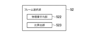
次に、第二変形例について説明する。この第二変形例では、前記フレーム選択部52は、図14に示すように、物理量平均部522及び比算出部523を有している。
Next, a second modification will be described. In the second modification, the
前記物理量平均部522は、前記各物理量フレームデータEFD1〜EFDnを構成する画素毎の歪みSのフレーム毎の平均値SrAVを算出する。前記物理量平均部522は、弾性画像作成領域である前記関心領域Rについてフレーム毎に平均値SrAVを算出する。前記物理量平均部522は、本発明における物理量平均部の実施の形態の一例である。
The physical quantity
前記比算出部523は、物理量フレームデータEFDにおける歪みSの平均の理想値SiAVに対する前記平均値SrAVの比Raを算出し、さらに後述するように(式1)の演算を行なってクオリティ値Qnを算出する。このクオリティ値Qnは、超音波画像Gにおける弾性画像EGが、生体組織の弾性をどれだけより正確に表したものであるかを示すものである。前記フレーム選択部52は、前記クオリティ値Qnを前記評価指標としてフレームの選択を行なう。前記比算出部523は、本発明における比較部及び比算出部の実施の形態の一例である。また、前記理想値SiAVは、本発明における予め設定された物理量の平均値の実施の形態の一例である。
The
ここで、前記理想値SiAVは、生体組織の弾性をより正確に反映した弾性画像を得ることができる強さで、超音波の送受信時に前記超音波プローブ2による生体組織への圧迫とその弛緩などによる変形を加えた場合に、任意に設定される領域において得られる歪みSの平均値である。この理想値SiAVは、例えば腫瘍と同じ硬さの部分や正常組織と同じ硬さの部分などからなるファントム等を対象として実験を行ない、経験上得られる値である。また、この理想値SiAVは、操作者が前記操作部9において設定できるようになっていてもよいし、デフォルトとして装置に記憶されていてもよい。
Here, the ideal value Si AV is a strength capable of obtaining an elastic image more accurately reflecting the elasticity of the living tissue, and the
この第二変形例の作用について説明すると、前記各物理量フレームデータEFD1〜EFDnのいずれかを選択するにあたり、先ず前記物理量平均部523が、前記各物理量フレームデータEFD1〜EFDnについて、前記関心領域R(前記領域R(i),R(ii))における歪みの平均値SrAVを算出する。ちなみに、歪みSは負になることもあることから、前記平均値SrAVは負になることもあるものとする。次に、前記比算出部523が、SrAV/SiAVの演算を行ない、前記比Raを算出する。さらに、前記比算出部523は、前記比Raを次の(式1)に代入し、数値Yを得る。
Y=1.0−|log10|Ra||・・・(式1)
ここで、Yは、前記クオリティ値Qnの一例であり、本発明において比較部による比較結果及び比較部の算出値の実施の形態の一例である。
The operation of the second modification will be described. In selecting any one of the physical quantity frame data EFD1 to EFDn, first, the physical
Y = 1.0− | log 10 | Ra || (Expression 1)
Here, Y is an example of the quality value Qn, and is an example of an embodiment of the comparison result by the comparison unit and the calculated value of the comparison unit in the present invention.
ちなみに、この(式1)は、前記比Raを0から1までの範囲にするためのものであり、この(式1)で得られるYは、前記理想値SiAVに対する平均値SrAVの比と同等である。この(式1)で表される関数をグラフで表すと、図15に示すグラフとなる。この図15に示すように、0≦Y≦1となる。 Incidentally, this (Equation 1) is for making the ratio Ra in the range from 0 to 1, and Y obtained by this (Equation 1) is the ratio of the average value Sr AV to the ideal value Si AV . Is equivalent to If the function represented by this (Formula 1) is represented with a graph, it will become a graph shown in FIG. As shown in FIG. 15, 0 ≦ Y ≦ 1.
また、0.1≦|Ra|≦10であるものとし、|Ra|がこの範囲を超えた場合、Yは零とする。 Further, it is assumed that 0.1 ≦ | Ra | ≦ 10, and when | Ra | exceeds this range, Y is set to zero.
0≦Y≦1であるため、0≦Qn≦1となる。クオリティ値Qnが1に近くなるほど、弾性画像EGのクオリティとしては良好であることを意味し、一方でクオリティ値Qnが0に近くなるほど、弾性画像EGのクオリティとしては悪くなることを意味する。ここで、弾性画像EGのクオリティが良好であるとは、生体組織の弾性をより正確に反映した弾性画像であることを意味し、一方で弾性画像のクオリティが悪いとは、生体組織の弾性を正確に反映した弾性画像ではないことを意味する。 Since 0 ≦ Y ≦ 1, 0 ≦ Qn ≦ 1. The closer the quality value Qn is to 1, the better the quality of the elastic image EG is. On the other hand, the closer the quality value Qn is to 0, the worse the quality of the elastic image EG is. Here, the quality of the elastic image EG means that the elasticity image reflects the elasticity of the living tissue more accurately, while the quality of the elasticity image is poor means that the elasticity of the living tissue is low. This means that the elastic image is not accurately reflected.
クオリティ値Qnと弾性画像EGのクオリティとの関係についてより詳細に説明すると、図15のグラフから分かるように、前記平均値SrAVが前記理想値SiAVと等しい場合(すなわち、|Ra|が1)、Yすなわちクオリティ値Qnは1となる。従って、クオリティ値Qnが1、または1に近い値であれば、前記超音波プローブ2による生体組織に対する圧迫とその弛緩の度合いが適切であり、生体組織の弾性を正確に反映した弾性画像EGが得られていることになる。
The relationship between the quality value Qn and the quality of the elastic image EG will be described in more detail. As can be seen from the graph of FIG. 15, when the average value Sr AV is equal to the ideal value Si AV (that is, | Ra | is 1). ), Y, that is, the quality value Qn is 1. Therefore, if the quality value Qn is 1 or a value close to 1, the degree of compression and relaxation of the living tissue by the
一方で、前記平均値SrAVが前記理想値SiAVと離れた値になるほど(すなわち、|Ra|が1から離れた値になるほど)、クオリティ値Qnは零に近づく。ここで、前記平均値SrAVが前記理想値SiAVと離れた値になるということは、前記超音波プローブ2による生体組織に対する圧迫やその弛緩の度合いが足りない、または過剰であることを意味する。従って、クオリティ値Qnが零に近づくほど、生体組織に対する圧迫やその弛緩の度合いが足りないか、または過剰である結果、生体組織の弾性を正確に反映した弾性画像EGが得られていないことになる。
On the other hand, the higher the average value Sr AV becomes a value away from the said ideal value Si AV (i.e., | Ra | more becomes a value far from 1), quality value Qn approaches zero. Means that here, the fact that the average value Sr AV becomes a value away from the said ideal value Si AV is said degree of compression and the relaxation to a living body tissue by the
以上のことから、前記フレーム選択部52は、前記クオリティ値Qnとして、最も1に近い値が得られた物理量フレームデータEFDを選択し、前記表示制御部6へ出力する。これにより、前記物理量フレームデータEFD1〜EFDnの中で、生体組織の弾性を最も正確に反映した弾性画像を得ることができる物理量フレームデータEFDが選択されることになる。
From the above, the
ここで、選択された物理量フレームデータEFDについて算出されたクオリティ値Qnを表すクオリティ表示を前記表示部7に表示するようにすることで、操作者等がクオリティ値Qnを把握できるようにしてもよい。前記クオリティ表示としては、例えば図16〜図18に示すように、横軸が時間、縦軸が前記クオリティ値Qnを表すグラフgrなどが挙げられる。このグラフgrは、前記表示部7に表示される弾性画像EGについてのクオリティ値Qnをプロットして得られるグラフである。このグラフgrは、図16〜図18に示すように、時間の経過とともに左から右へ流れるように表示される。この場合、前記グラフgrの左端が現在表示されているフレームのクオリティ値を表す。
Here, by displaying a quality display indicating the quality value Qn calculated for the selected physical quantity frame data EFD on the
第二変形例において、前記物理量平均部522は、相関係数C(0≦C≦1)が所定の閾値CTH以上である相関演算が行なわれた相関ウィンドウを選択してその歪みSの平均算出を行ない、平均値SrAV′を得るようにしてもよい。この場合、前記比算出部612が、前記平均値SrAV′を用いて前記比Raを算出し、また(式1)を用いてYを算出してクオリティ値Qnを得る。
In the second modification, the physical
ここで、前記平均値SrAV′は、エコーの信号強度が不十分な部分、生体組織の横ずれが生じている部分など、相関係数が低い部分の変位が除かれて得られた平均値である。従って、このような平均値SrAV′から得られたクオリティ値Qnは、前記超音波プローブ2による圧迫とその弛緩が適切な強さで行なわれているか否かを示すものとなる。
Here, the average value Sr AV ′ is an average value obtained by removing the displacement of a portion having a low correlation coefficient, such as a portion where the signal strength of the echo is insufficient or a portion where the lateral displacement of the living tissue occurs. is there. Accordingly, the quality value Qn obtained from the average value Sr AV ′ indicates whether or not the compression and relaxation by the
また、第二変形例において、前記フレーム選択部52は、図19に示すように、前記相関係数平均部521、前記物理量平均部522、前記比算出部523を有するとともに、さらに乗算部524を有していてもよい。前記乗算部524は、本発明における乗算部の実施の形態の一例である。
In the second modification, the
図19に示す構成の前記フレーム選択部52において、前記相関係数平均部521は相関係数Cの平均値CAVを算出する。また、前記物理量平均部522は、相関係数Cが所定の閾値CTH以上である相関演算が行なわれた相関ウィンドウを選択してその変位の平均値SrAV′を算出し、また前記比算出部523が、前記平均値SrAV′を用いて前記比Raを算出し、前記(式1)からYを算出する。
In the
そして、前記乗算部524は、前記相関係数平均部521で得られた相関係数Cの平均値CAVと、前記比算出部523で得られた算出値Yとを乗算し、乗算値Mを算出する。この乗算値Mは、前記各物理量フレームデータEFD1〜EFDnについて算出される。ここでは、この乗算値Mをクオリティ値Qnとし、前記フレーム選択部52による前記物理量フレームデータEFDの選択の評価指標とする。
Then, the
ここで、0≦Y≦1、0≦CAV≦1であるので、0≦M≦1となる。従って、本例においても、0≦Qn≦1である。前記乗算値Mは、前記算出値Yと前記相関係数Cの平均値CAVとの乗算値であるため、乗算値M、すなわちクオリティ値Qnが1に近づくほど弾性画像EGのクオリティが良好になり、一方でQnが零に近づくほど弾性画像EGのクオリティが悪くなる。従って、前記フレーム選択部52は、前記乗算値Mが最も1に近い物理量フレームデータEFDを選択する。
Here, since 0 ≦ Y ≦ 1 and 0 ≦ C AV ≦ 1, 0 ≦ M ≦ 1. Therefore, also in this example, 0 ≦ Qn ≦ 1. The multiplication value M are the average multiplication value between C AV of the correlation coefficient C and the calculated value Y, multiplication value M, i.e. the higher the elastic image EG quality value Qn approaches 1 quality is good On the other hand, the quality of the elastic image EG deteriorates as Qn approaches zero. Therefore, the
ここで、前記乗算部524は、前記算出値Yと前記相関係数Cの平均値CAVとを乗算する時に、重み付けをして乗算してもよい。
Here, the
ここで、上述のように、所定の閾値CTH以上の相関係数Cの相関演算で得られた歪みの平均値SrAV′から算出された算出値Yをクオリティ値Qnとし、前記物理量フレームデータEFDを選択する評価指標とすると、相関係数は評価指標として全く反映されないことになる。一方で、相関係数Cの平均値CAVが最も高い物理量フレームデータEFDを選択するようにした場合、すなわち前記評価指標として前記平均値CAVを用いる場合には、前記超音波プローブ2による生体組織への圧迫とその弛緩の度合いが足りなかったとしても、相関係数Cとしては高くなるために、前記評価指標としての前記クオリティ値Qnとしては良好な値が得られることになる。従って、ここでは、前記平均値SrAV′を用いて算出された前記比Raを用いて得られる算出値Yと前記相関係数Cの平均値CAVとを乗算することにより、生体組織への圧迫とその弛緩の度合いの要素と、相関係数の要素とを加味したクオリティ値Qnを算出し、これを前記評価指標として前記物理量フレームデータEFDの選択を行なうようにしている。
Here, as described above, the calculated value Y calculated from the average value Sr AV ′ of the distortion obtained by the correlation calculation of the correlation coefficient C equal to or greater than the predetermined threshold C TH is set as the quality value Qn, and the physical quantity frame data When the evaluation index for selecting EFD is used, the correlation coefficient is not reflected at all as the evaluation index. On the other hand, if you like the average value C AV of the correlation coefficient C is to select the highest physical quantity frame data EFD, i.e. in the case of using the average value C AV as the evaluation index, the biological by the
なお、前記評価指標としてのクオリティ値Qnは、算出値Y及び乗算値Mの中から、操作者等が前記操作部9において選択できるようになっていてもよい。
The quality value Qn as the evaluation index may be selected by the operator or the like from the calculated value Y and the multiplied value M on the
なお、上述の説明では、前記物理量フレームデータEFDを対象にしてクオリティ値Qnを算出し、選択を行なうようになっているが、前記カラー弾性画像データEGDについて、各画素のデータを用いて同様にしてクオリティ値Qnを算出し、カラー弾性画像データEGの選択を行うようになっていてもよい。この場合には、前記カラー弾性画像データが、本発明における弾性データの実施の形態の一例である。 In the above description, the quality value Qn is calculated and selected for the physical quantity frame data EFD, but the color elastic image data EGD is similarly used by using the data of each pixel. The quality value Qn may be calculated to select the color elastic image data EG. In this case, the color elasticity image data is an example of an embodiment of elasticity data in the present invention.
次に、第三変形例について説明する。この第三変形例では、前記フレーム選択部52は、前記各物理量フレームデータEFD1〜EFDnにおけるSの正負の符号の割合を評価指標として、前記物理量フレームデータEFDの選択を行なう。
Next, a third modification will be described. In the third modification, the
ここで、歪みSは、前記超音波プローブ2による圧迫とその弛緩に応じた正負の符合を伴って算出される。例えば、圧迫方向を正方向とすると、前記超音波プローブ2による圧迫時に取得されたエコーデータに基づいて算出される歪みSは正の符号を伴って算出され、一方で弛緩時に取得されたエコーデータに基づいて算出される歪みSは負の符号を伴って算出される。
Here, the strain S is calculated with a positive / negative sign corresponding to the compression by the
前記歪みSの正負の符合の割合を評価指標とする物理量フレームデータEFDの選択について具体的に説明すると、前記フレーム選択部52は、前記各物理量フレームデータEFD1〜EFD3について、正の歪みSのデータと負の歪みSのデータの比を算出し、算出された比が最も大きいフレームの物理量フレームデータEFDを選択する。
The selection of the physical quantity frame data EFD using the ratio of the positive / negative sign of the distortion S as an evaluation index will be described in detail. The
ここで、一のフレームにおける歪みSの正負の符号の比と弾性画像EGのクオリティとの関係について説明する。例えば、前記超音波プローブ2による圧迫とその弛緩が適切になされていれば、一のフレームにおける歪みSの符合の割合としては、正又は負のいずれか一方の符合の割合が大きくなる(すなわち、正と負の比が大きくなる)。しかし、前記超音波プローブ2による圧迫とその弛緩の方向が適切でなく、生体組織に横ずれなどが生じている場合には、一のフレームにおける歪みSの符合の割合は、正又は負のいずれか一方に偏らず、双方の符号の割合が拮抗したものになってくる(すなわち、正と負の比が小さくなる)。従って、よりクオリティの高い弾性画像EGを得ることができるように、前記フレーム選択部52は正の歪みSのデータと負の歪みSのデータの比が最も大きい物理量フレームデータEFDを選択する。
Here, the relationship between the ratio of the sign of the strain S in one frame and the quality of the elastic image EG will be described. For example, if the compression by the
(第三実施形態)
次に、第三実施形態について説明する。なお、以下の説明では、前記各実施形態と異なる事項について説明する。
(Third embodiment)
Next, a third embodiment will be described. In the following description, matters different from the above embodiments will be described.
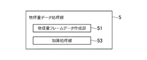
本例の超音波診断装置1において、前記物理量データ処理部5は、図20に示すように前記物理量フレームデータ作成部51と加算処理部53とを有する。この加算処理部53は、一の走査面Pnについて得られた複数フレーム分の物理量フレームデータEFDを重み付け加算処理して加算物理量フレームデータaEFDを作成する。詳細は後述する。前記加算処理部53は、本発明における加算処理部の実施の形態の一例であり、また加算物理量フレームデータは、本発明における加算弾性データの実施の形態の一例である。
In the ultrasonic
本例の作用について説明する。本例においても、第二実施形態と同様の走査を行なうものとする(図11参照)。そして、第二実施形態と同様に、前記物理量フレームデータ作成部51は、前記フレームデータFDe11,FDe21に基づいて物理量フレームデータEFD1を作成し、前記フレームデータFDe12,FDe22に基づいて物理量フレームデータEFD2を作成し、前記フレームデータFDe1n,FDe2nに基づいて物理量フレームデータEFDnを作成する。
The operation of this example will be described. In this example, the same scanning as in the second embodiment is performed (see FIG. 11). Similarly to the second embodiment, the physical quantity frame
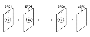
前記加算処理部53は、前記物理量フレームデータEFD1,EFD2,・・・,EFDnを、下記の(式2)に示すように重み付け加算処理して加算物理量フレームデータaEFDを作成する(図21参照)。
aEFD=k1×EFD1+k2×EFD2+・・・+kn×EFDn
・・・(式2)
ただし、(式2)において、k1,k2,・・・,knは重み付け係数であり、k1+k2+・・・,+kn=1である。これら重み付け係数k1〜knは、操作者が前記操作部9において任意の値を設定することができるようになっていてもよい。
The
aEFD = k1 × EFD1 + k2 × EFD2 +... + kn × EFDn
... (Formula 2)
However, in (Equation 2), k1, k2,..., Kn are weighting coefficients, and k1 + k2 +. These weighting coefficients k1 to kn may be set so that an operator can set arbitrary values in the
前記表示制御部6には、前記加算物理量フレームデータaEFDが出力されて前記メモリ61に記憶される。また、Bモード画像用走査Bs1〜Bsnのうち、最も新しい走査であるBモード画像用走査Bsnで得られたフレームデータFDbに基づくBモードフレームデータBFDが前記メモリ61に記憶される。そして、前記加算物理量フレームデータaEFDに基づいて作成されたカラー弾性画像データEGDが、前記BモードフレームデータBFDに基づいて作成されたBモード画像データBGDと合成されて前記超音波画像Gが前記表示部7に表示される。
The
前記メモリ61には、各走査面Pについて前記BモードフレームデータBFD及び前記加算物理量フレームデータaEFDが記憶され、これらBモードフレームデータBFD及び加算物理量フレームデータaEFDに基づいて前記三次元画像や三次元の弾性画像が作成され表示される。
The
本例によれば、一の走査面Pnについて複数フレーム分の物理量フレームデータを重み付け加算処理して得られた前記加算物理量フレームデータaEFDに基づく弾性画像EGや、前記三次元画像又は三次元の弾性画像が表示されるので、生体組織の弾性をより正確に反映した画像を表示することができる。 According to this example, the elasticity image EG based on the added physical quantity frame data aEFD obtained by weighting and adding physical quantity frame data for a plurality of frames for one scanning plane Pn, the three-dimensional image, or the three-dimensional elasticity. Since the image is displayed, it is possible to display an image that more accurately reflects the elasticity of the living tissue.
なお、上述の説明では、前記物理量フレームデータEFDについて重み付け加算処理を行なうようになっているが、前記カラー弾性画像データEGDについて重み付け加算処理を行なうようになっていてもよい。この場合には、前記カラー弾性画像データが、本発明における弾性データの実施の形態の一例である。 In the above description, weighted addition processing is performed on the physical quantity frame data EFD, but weighted addition processing may be performed on the color elastic image data EGD. In this case, the color elasticity image data is an example of an embodiment of elasticity data in the present invention.
(第四実施形態)
次に、第四実施形態について説明する。なお、以下の説明では、前記各実施形態と異なる事項について説明する。
(Fourth embodiment)
Next, a fourth embodiment will be described. In the following description, matters different from the above embodiments will be described.
本例の超音波診断装置1において、前記物理量データ処理部5は、図22に示すように前記物理量フレームデータ作成部51と置換済物理量フレームデータ作成部54とを有する。この置換済物理量フレームデータ作成部54は、一の走査面Pnについて得られた複数フレームの物理量フレームデータEFDのうち、一のフレームの物理量フレームデータEFDにおけるエラー画素の歪みデータを、他のフレームの物理量フレームデータEFDにおける非エラー画素の歪みデータに置換して置換済物理量フレームデータを作成する。詳細は後述する。前記置換済物理量フレームデータ作成部54は、本発明における置換済弾性データ作成部の実施の形態の一例であり、また前記置換済物理量フレームデータは、本発明における置換済弾性データの実施の形態の一例である。
In the ultrasonic
本例の作用について説明する。本例においても、第二、第三実施形態と同様の走査を行なうものとする(図11参照)。そして、第二、第三実施形態と同様に、前記物理量フレームデータ作成部51は、前記フレームデータFDe11,FDe21に基づいて物理量フレームデータEFD1を作成し、前記フレームデータFDe12,FDe22に基づいて物理量フレームデータEFD2を作成し、前記フレームデータFDe1n,FDe2nに基づいて物理量フレームデータEFDnを作成する。
The operation of this example will be described. In this example, the same scanning as in the second and third embodiments is performed (see FIG. 11). As in the second and third embodiments, the physical quantity frame
前記置換済物理量フレームデータ作成部54は、例えば、前記物理量フレームデータEFD1におけるエラー画素の歪みデータを、前記物理量フレームデータEFD2又はこの物理量フレームデータBFD2よりも後のフレームの物理量フレームデータBFDの非エラー画素の歪みデータに置換して、置換済物理量フレームデータbEFDを作成する。
For example, the replaced physical quantity frame
具体的には、先ず前記置換済物理量フレームデータ作成部54は、前記物理量フレームデータEFD1の各画素の歪みデータについて、エラーか否かを判定し、エラー画素の特定を行なう。このエラー画素の特定の手法は、第二実施形態と同様であり、歪みSや相関係数Cに基づいて特定される。
Specifically, the replaced physical quantity frame
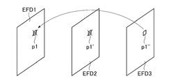
次に、前記置換済物理量フレームデータ作成部54は、前記物理量フレームデータEFD1におけるエラー画素の歪みデータを、前記物理量フレームデータEFD2における同一画素の歪みデータに置換できるか否かを判定する。例えば、図23に示すように、前記物理量フレームデータEFD1における画素p1の歪みデータがエラーである場合、前記置換済物理量フレームデータ作成部54は、前記物理量フレームデータEFD2において、前記画素p1と同一画素である画素p1′の歪みデータがエラーであるか否かを判定する。エラーか否かの判定手法は、上述と同様のエラー画素の特定の手法である。
Next, the replaced physical quantity frame
そして、前記置換済物理量フレームデータ作成部54は、前記画素p1′の歪みデータがエラーでない場合、前記物理量フレームデータEFD1の前記画素p1の歪みデータを、前記画素p1′の歪みデータに置換する。一方、図24に示すように、前記画素p1′の歪みデータがエラーである場合、前記置換済物理量フレームデータ作成部54は、前記画素p1′の歪みデータへの置換を行なわず、前記物理量フレームデータEFD2の次のフレームの物理量フレームデータEFD3において、前記画素p1と同一画素である画素p1′′の歪みデータがエラーであるか否か判定する。そして、エラーでなければ、前記画素p1の歪みデータを前記画素p1′′の歪みデータに置換する。
Then, if the distortion data of the pixel p1 ′ is not an error, the replaced physical quantity frame
前記置換済物理量フレームデータ作成部54は、このようにして前記物理量フレームデータEFD1における全てのエラー画素の歪みデータを前記物理量フレームデータEFD2,EFD3,・・・,EFDnのいずれかにおける非エラー画素の歪みデータに置換し、前記置換済物理量フレームデータbEFDを作成する。ただし、ここでは物理量フレームデータBFD1が置換される対象になっているが、他の物理量フレームデータBFDが置換される対象になっていてもよい。例えば、置換される対象が前記物理量フレームデータEFD2である場合には、前記物理量フレームデータEFD2におけるエラー画素の歪みデータを、他の物理量フレームデータEFD1,EFD3,・・・,EFDnにおける非エラー画素の歪みデータに置換して置換済物理量フレームデータbEFDを作成する。また、前記物理量フレームデータEFD3におけるエラー画素の歪みデータを、前記物理量フレームデータEFD1,EFD2,・・・,EFDnにおける非エラー画素の歪みデータに置換して置換済物理量フレームデータbEFDを作成する。
In this way, the replaced physical quantity frame
前記表示制御部6には、前記置換済物理量フレームデータbEFDが出力されて前記メモリ61に記憶される。また、置換される対象の物理量フレームデータと対になるBモードフレームデータBFD(前記Bモード画像用走査Bs1で得られたフレームデータFDbに基づくデータ)が記憶される。そして、前記置換済物理量フレームデータbEFDに基づいて作成されたカラー弾性画像データEGDが、前記BモードフレームデータBFDに基づいて作成されたBモード画像データBGDと合成されて前記超音波画像Gが前記表示部7に表示される。
The replaced physical quantity frame data bEFD is output to the
前記メモリ61には、各走査面Pについて前記BモードフレームデータBFD及び前記置換済物理量フレームデータbEFDが記憶され、これらBモードフレームデータBFD及び置換済物理量フレームデータbEFDに基づいて前記三次元画像や三次元の弾性画像が作成され表示される。
The
本例によれば、一の走査面Pnについて、エラー画素の歪みデータが非エラー画素の歪みデータに置換されて得られた前記置換済物理量フレームデータbEFDに基づく弾性画像EGや、前記三次元画像又は三次元の弾性画像が表示されるので、生体組織の弾性をより正確に反映した画像を表示することができる。 According to this example, for one scanning plane Pn, the elastic image EG based on the replaced physical quantity frame data bEFD obtained by replacing the distortion data of error pixels with the distortion data of non-error pixels, or the three-dimensional image Alternatively, since a three-dimensional elasticity image is displayed, an image that more accurately reflects the elasticity of the living tissue can be displayed.
なお、上述の説明では、前記物理量フレームデータEFDを対象にしてエラー画素の歪みデータの置換を行なっているが、前記カラー弾性画像データEGDを対象にしてエラー画素のデータの置換を行ってもよい。この場合には、前記カラー弾性画像データが、本発明における弾性データの実施の形態の一例である。 In the above description, error pixel distortion data is replaced with the physical quantity frame data EFD. However, error pixel data may be replaced with the color elastic image data EGD. . In this case, the color elasticity image data is an example of an embodiment of elasticity data in the present invention.
(第五実施形態)
次に、第五実施形態について説明する。なお、以下の実施形態では前記各実施形態と異なる事項について説明する。
(Fifth embodiment)
Next, a fifth embodiment will be described. In the following embodiments, matters different from those in the above embodiments will be described.
前記第一〜第四実施形態では、前記送受信部3は、予め設定されたフレーム数や予め設定された時間の長さだけ一の走査面Pnにおける走査を行なった後、他の走査面P(n+1)への走査面の切替えを行なうようになっているが、この第五実施形態では前記送受信部3は、一の走査面Pnについて、所定の画質の弾性画像を得ることができる物理量フレームデータEFDが得られると、他の走査面P(n+1)に走査面を切り替えるようになっている。詳細は後述する。
In the first to fourth embodiments, the transmission /
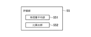
本例では、前記物理量データ処理部5は、図25に示すように、物理量フレームデータ作成部51と、評価部55を有している。この評価部55は、後述するように、前記物理量フレームデータEFDについて、前記所定の評価指標に基づいて、所定の画質の弾性画像を得られる物理量フレームデータEFDであるか否かの評価を行なう。前記評価部55は、所定の画質の弾性画像EGを得られる物理量フレームデータEFDであると評価した場合、そのことを示す信号を前記制御部8へ出力する。そして、所定の画質の弾性画像EGを得られると評価された物理量フレームデータEFDに基づいて弾性画像EGが作成される。
In this example, the physical quantity
本例の作用について説明する。本例では、一の走査面PnについてBモード画像用走査BSを一フレーム分行なった後、二フレーム分の弾性画像用走査ES1,ES2を行なう。そして、前記弾性画像用走査ES1で得られるフレームデータFDe1と前記弾性画像用走査ES2で得られるフレームデータFDe2とに基づいて前記物理量フレームデータEFDが作成されると、前記評価部55は、前記物理量フレームデータEFDについて所定の評価指標として前記クオリティ値Qnを算出し、このクオリティ値Qnが所定の閾値QnTH以上であるか否かを判定する。
The operation of this example will be described. In this example, one scan plane Pn after performing one frame scanning B S for B-mode image, performs a two-frame portion of the elastic image scanning E S 1, E S 2. When the elastic image scan E the physical quantity frame data EFD based on the frame data FDe2 the frame data FDe1 obtained in S 1 obtained by the elastic image scan E S 2 is created, the
前記所定の閾値QnTHは、所定の画質の弾性画像EGを得ることができる値に設定される。所定の画質とは、生体組織の弾性をある程度正確に反映した画像をいう。ここで、前記閾値QnTHが高くなるほど、生体組織の弾性をより正確に反映した弾性画像を得ることができるものの、高く設定しすぎると閾値以上の物理量フレームデータが得られにくくなり、フレームレートが低下するおそれがある。そこで、前記閾値QnTHは、ある程度正確な弾性画像が得られ、なおかつフレームレートが低下しすぎないような閾値に設定される。 The predetermined threshold value Qn TH is set to a value capable of obtaining an elastic image EG having a predetermined image quality. The predetermined image quality refers to an image that accurately reflects the elasticity of a living tissue to some extent. Here, as the threshold value Qn TH increases, an elasticity image that more accurately reflects the elasticity of the living tissue can be obtained. However, if the threshold value Qn TH is set too high, it becomes difficult to obtain physical quantity frame data that exceeds the threshold value, and the frame rate is increased. May decrease. Therefore, the threshold value Qn TH is set to a threshold value that allows an elastic image that is accurate to some extent to be obtained and that the frame rate does not decrease too much.
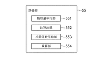
ちなみに、前記クオリティ値Qnは、前記算出値Y及び前記乗算値Mのいずれかである。前記クオリティ値Qnが前記算出値Yである場合、前記評価部55は、図26に示すように物理量平均部551と比算出部552とを有する。これら物理量平均部551及び比算出部552は、前記物理量平均部522及び比算出部523と同一であり、詳細な説明を省略する。また、前記クオリティ値Qnが前記乗算値Mである場合、前記評価部55は、図27に示すように、前記物理量平均部551、前記比算出部552、相関係数平均部553及び乗算部554を有する。前記相関係数平均部553及び前記乗算部554も、前記相関係数平均部521及び前記乗算部524と同一であり、詳細な説明を省略する。
Incidentally, the quality value Qn is either the calculated value Y or the multiplied value M. When the quality value Qn is the calculated value Y, the
前記評価部55は、クオリティ値Qnが所定の閾値QnTH以上である場合、そのことを示す信号を前記制御部8へ出力する。そして、前記制御部8は、前記評価部55からの信号の入力があると、走査面を次の走査面P(n+1)に切り替えるよう前記送受信部3へ指示信号を出力し、これにより送受信部3は走査面の切替えを行なう。
When the quality value Qn is greater than or equal to a predetermined threshold value Qn TH , the
一方、前記評価部55が、前記クオリティ値Qnが前記閾値QnTH未満であると判定した場合、前記制御部8は、再度Bモード画像用走査BSを一フレーム分行ない、その後二フレーム分の弾性画像用走査ES1,ES2を行なわせるよう、前記送受信部3へ指示信号を出力する。そして、前記弾性画像用走査ES1,ES2で得られたフレームデータFD1,FD2に基づいて作成される物理量フレームデータEFDについて、前記評価部55は、上述と同様にクオリティ値Qnを算出し、このクオリティ値Qnが前記閾値QnTH以上であれば、そのことを示す信号を前記制御部8へ出力する。
Meanwhile, the
以上のように、前記物理量フレームデータ作成部51が、物理量フレームデータEFDについて所定の閾値QnTH以上であるか否かを判定し、前記クオリティ値Qnが前記閾値QnTH以上であれば走査面の切替えを行なう。一方、前記クオリティ値Qnが前記閾値QnTH未満であれば、同じ走査面について、さらにBモード画像用走査BSと弾性画像用走査ES1,ES2を行ない、得られた物理量フレームデータEFDについて再度前記クオリティ値Qnが前記閾値QnTH以上であるか否かの判定を行なう。そして、クオリティ値Qnが前記閾値QnTH以上の物理量フレームデータが得られるまで、Bモード画像用走査BSと弾性画像用走査ES1,ES2を繰り返し行なう。
As described above, the physical quantity frame
前記物理量データ処理部5からは、前記クオリティ値Qnが所定の閾値QnTH以上である物理量フレームデータEFD及びこれと対のBモードフレームデータBFDが前記表示制御部6へ出力されて前記メモリ61に記憶される。そして、前記物理量フレームデータEFDに基づいて作成されたカラー弾性画像データEGDが、前記BモードフレームデータBFDに基づいて作成されたBモード画像データBGDと合成されて前記超音波画像Gが前記表示部7に表示される。
From the physical quantity
前記メモリ61には、前記クオリティ値Qnが所定の閾値QnTH以上である物理量フレームデータEFD及びこれと対のBモードフレームデータBFDが、各走査面Pについて記憶され、これら物理量フレームデータEFD及びBモードフレームデータBFDに基づいて前記三次元画像や三次元の弾性画像が作成され表示される。
In the
本例によれば、一の走査面Pnについて、所定の画質の弾性画像EGを得ることができる物理量フレームデータEFDが得られると、次の走査面P(n+1)に走査面の切替えを行なうので、各走査面について、生体組織の弾性をより正確に反映した弾性画像EGや、前記三次元画像又は三次元の弾性画像を表示することができる。 According to this example, when the physical quantity frame data EFD capable of obtaining an elastic image EG having a predetermined image quality is obtained for one scanning plane Pn, the scanning plane is switched to the next scanning plane P (n + 1). For each scanning plane, it is possible to display the elasticity image EG reflecting the elasticity of the living tissue more accurately, the three-dimensional image, or the three-dimensional elasticity image.
なお、前記評価部55は、前記物理量平均部551によって算出された歪みの平均値SrAVを評価指標とし、この平均値SrAVが所定の範囲内にあるか否か、すなわちm≦SrAV≦nであるか否かを判定してもよい。この場合、前記評価部55は、m≦SrAV≦nであれば、そのことを示す信号を前記制御部8へ出力する。一方、m>SrAV又はn<SrAVであれば、再度同一走査面についてBモード画像用走査BS及び弾性画像用走査ES1,ES2を行ない、得られた物理量フレームデータEFDについて、m≦SrAV≦nであるか否かを判定する。
Incidentally, the
ちなみに、前記所定の範囲(m,n)は、例えば生体組織の弾性を考慮して通常考えられる歪み値の範囲に設定されるものであり、著しく逸脱した歪み値をエラーとするような値に設定される。m≦SrAV≦nである物理量フレームデータEFDであれば、所定の画質の弾性画像EGを得ることができる Incidentally, the predetermined range (m, n) is set to a strain value range that is normally considered in consideration of, for example, the elasticity of the living tissue, and is set to a value that causes a significantly deviated strain value to be an error. Is set. If the physical quantity frame data EFD satisfies m ≦ Sr AV ≦ n, an elastic image EG having a predetermined image quality can be obtained.
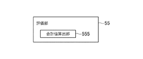
また、歪みの平均値SrAVの代わりに一フレームにおける歪みSの合計値を用いてもよい。すなわち、前記評価部55は、図28に示すように、前記物理量フレームデータEFDにおける各画素の歪みSの合計値を算出する合計値算出部555を有し、前記評価部55は、この合計値算出部555の算出値が所定の範囲内であるか否かを判定してもよい。
It may also be used the sum of the strain S in one frame instead of the average value Sr AV distortion. That is, as shown in FIG. 28, the
なお、上述の説明では、前記物理量フレームデータEFDを対象にして評価を行なうようになっているが、前記カラー弾性画像データEGDについて、各画素のデータを用いて同様にして評価を行うようになっていてもよい。この場合には、前記カラー弾性画像データが、本発明における弾性データの実施の形態の一例である。 In the above description, the physical quantity frame data EFD is evaluated, but the color elastic image data EGD is evaluated in the same manner using the data of each pixel. It may be. In this case, the color elasticity image data is an example of an embodiment of elasticity data in the present invention.
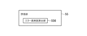
次に、第五実施形態の変形例について説明する。先ず、第一変形例について説明する。第一変形例では、図29に示すように、前記評価部55は、物理量フレームデータEFDについて、エラー画素数を算出するエラー画素数算出部556を有する。このエラー画素数算出部556は、前記フレーム選択部52と同様にしてエラー画素の特定を行ない、前記評価指標として、前記物理量フレームデータEFDにおけるエラー画素数を算出する。そして、前記評価部55は、一の走査面Pnについて得られた物理量フレームデータEFDについて、エラー画素数が所定数eを超えるか否かを判定する。前記評価部55は、エラー画素数が所定数e以下である場合、そのことを示す信号を前記制御部8へ出力する。これにより、前記送受信部3は走査面の切替えを行なう。そして、後述のようにエラー画素数が所定数e以下である物理量フレームデータEFDに基づく弾性画像EGが作成される。
Next, a modification of the fifth embodiment will be described. First, the first modification will be described. In the first modified example, as shown in FIG. 29, the
ちなみに、前記所定数eは、所定の画質の弾性画像を得ることができる値に設定される。ここで、前記所定数eを小さく設定するほど、生体組織の弾性画像をより正確に反映した弾性画像を得ることができるものの、小さく設定しすぎると所定数e以下の物理量フレームデータEFDが得られにくくなり、フレームレートが低下するおそれがある。そこで、前記所定数eは、ある程度正確な弾性画像が得られ、なおかつフレームレートが低下しすぎないような値に設定される。 Incidentally, the predetermined number e is set to a value capable of obtaining an elastic image having a predetermined image quality. Here, as the predetermined number e is set smaller, an elastic image that more accurately reflects the elastic image of the living tissue can be obtained. However, if the predetermined number e is set too small, physical quantity frame data EFD of the predetermined number e or less is obtained. This may make it difficult to reduce the frame rate. Therefore, the predetermined number e is set to such a value that an elastic image accurate to some extent can be obtained and the frame rate does not decrease too much.
一方、エラー画素数が所定数eを超える場合、再度Bモード画像用走査BS及び弾性画像用走査ES1,ES2を行ない、得られた物理量フレームデータEFDについて、エラー画素数が前記所定数eを超えるか否かの判定を行なう。
On the other hand, when the number of error pixels exceeds the predetermined number e, the B-mode image scan B S and the elastic
前記物理量データ処理部5からは、エラー画素数が所定数e以下である物理量フレームデータEFD及びこれと対のBモードフレームデータBFDが前記表示制御部6へ出力されて前記メモリ61に記憶される。そして、前記物理量フレームデータEFDに基づいて作成されたカラー弾性画像データEGDが、前記BモードフレームデータBFDに基づいて作成されたBモード画像データBGDと合成されて前記超音波画像Gが前記表示部7に表示される。
The physical quantity
前記メモリ61には、エラー画素数が所定数e以下である物理量フレームデータEFD及びこれと対のBモードフレームデータBFDが、各走査面Pについて記憶され、これら物理量フレームデータEFD及びBモードフレームデータに基づいて前記三次元画像や三次元の弾性画像が作成され表示される。
In the
なお、上述の説明では、前記物理量フレームデータEFDについての評価を行なうようになっているが、前記カラー弾性画像データEGDについての評価を行うようになっていてもよい。この場合には、前記カラー弾性画像データが、本発明における弾性データの実施の形態の一例である。 In the above description, the physical quantity frame data EFD is evaluated. However, the color elastic image data EGD may be evaluated. In this case, the color elasticity image data is an example of an embodiment of elasticity data in the present invention.
次に第二変形例について説明する。この第二変形例では、図30に示すように、前記評価部55は、前記相関係数平均部553を有する。そして、前記評価部55は、一の走査面Pnについて得られた物理量フレームデータEFDについて、相関係数の平均値CAVが所定の閾値CTH以上であるか否かを判定する。前記評価部55は、前記平均値CAVが閾値CTH以上である場合、そのことを示す信号を前記制御部8へ出力する。これにより、前記送受信部3は走査面の切替えを行なう。そして、後述のように前記平均値CAVが閾値CTH以上である物理量フレームデータEFDに基づく弾性画像EGが作成される。
Next, a second modification will be described. In the second modified example, as shown in FIG. 30, the
ちなみに、前記閾値CTHは、所定の画質の弾性画像を得ることができる値に設定される。ここで、前記閾値CTHを大きく設定するほど、生体組織の弾性画像をより正確に反映した弾性画像を得ることができるものの、大きく設定しすぎると閾値CTH以上の物理量フレームデータEFDが得られにくくなり、フレームレートが低下するおそれがある。そこで、前記閾値CTHは、ある程度正確な弾性画像が得られ、なおかつフレームレートが低下しすぎないような値に設定される。 Incidentally, the threshold value C TH is set to a value capable of obtaining an elastic image having a predetermined image quality. Here, as the larger the threshold value C TH, although elastic image of the biological tissue can be obtained more accurately elastic image that reflects the, is set too large the threshold value C TH or more physical quantity frame data EFD obtained This may make it difficult to reduce the frame rate. Therefore, the threshold value C TH is set to a value such that an elastic image accurate to some extent can be obtained and the frame rate does not decrease too much.
一方、前記平均値CAVが前記閾値CTHを超える場合、再度Bモード画像用走査BS及び弾性画像用走査ES1,ES2を行ない、得られた物理量フレームデータEFDについて、相関係数の平均値CAVが前記閾値CTHを超えるか否かの判定を行なう。
On the other hand, the case where the average value C AV exceeds the threshold C TH, performs B-mode image scanning B S and
前記物理量データ処理部5からは、前記相関係数Cの平均値CAVが前記閾値CTH以上である物理量フレームデータEFD及びこれと対のBモードフレームデータBFDが前記表示制御部6へ出力されて前記メモリ61に記憶される。そして、この物理量フレームデータEFDに基づいて作成されたカラー弾性画像データEGDが、前記BモードフレームデータBFDに基づいて作成されたBモード画像データBGDと合成されて前記超音波画像Gが前記表示部7に表示される。
From the physical quantity
前記メモリ61には、前記相関係数Cの平均値CAVが前記閾値CTH以上である物理量フレームデータEFD及びこれと対のBモードフレームデータBFDが、各走査面Pについて記憶され、これら物理量フレームデータEFD及びBモードフレームデータBFDに基づいて前記三次元画像や三次元の弾性画像が作成され表示される。
In the
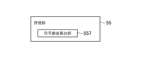
次に第三変形例について説明する。この第三変形例では、図31に示すように、前記評価部55は、物理量フレームデータEFDにおける歪みSの正負の符合の割合を算出する符合割合算出部557を有する。この符合割合算出部557は、第二実施形態の第三変形例の前記フレーム選択部52と同様に、一の走査面Pnについて得られた物理量フレームデータEFDにおける正の歪みSのデータと負の歪みSのデータの比を算出する。そして、前記評価部55は、正の歪みSのデータと負の歪みSのデータの比が所定の大きさ以上であるか否かを判定する。前記評価部55は、正の歪みSのデータと負の歪みSのデータの比が所定の大きさ以上である場合、そのことを示す信号を前記制御部8へ出力する。これにより、前記送受信部3は走査面の切替えを行なう。そして、後述のように、正の歪みSのデータと負の歪みSのデータの比が所定の大きさ以上である物理量フレームデータEFDに基づく弾性画像EGが作成される
Next, a third modification will be described. In the third modified example, as shown in FIG. 31, the
ちなみに、前記比についての所定の大きさは、所定の画質の弾性画像を得ることができるものに設定される。ここで、前記比についての所定の大きさを大きく設定するほど(大きな比に設定するほど)、生体組織の弾性画像をより正確に反映した弾性画像を得ることができるものの、大きく設定しすぎると前記所定の大きさの比以上の物理量フレームデータEFDが得られにくくなり、フレームレートが低下するおそれがある。そこで、前記比についての所定の大きさは、ある程度正確な弾性画像が得られ、なおかつフレームレートが低下しすぎないようなものに設定される。 Incidentally, the predetermined size for the ratio is set to be able to obtain an elastic image having a predetermined image quality. Here, the larger the predetermined size of the ratio is set (the larger the ratio is set), the more the elastic image that reflects the elasticity image of the living tissue can be obtained more accurately. It is difficult to obtain physical quantity frame data EFD that is equal to or greater than the ratio of the predetermined size, and the frame rate may be reduced. Therefore, the predetermined size for the ratio is set such that an elastic image accurate to some extent is obtained and the frame rate does not decrease too much.
一方、正の歪みSのデータと負の歪みSのデータの比が前記所定の大きさを下回る場合、再度Bモード画像用走査BS及び弾性画像用走査ES1,ES2を行ない、得られた物理量フレームデータEFDについて、正の歪みSのデータと負の歪みSのデータの比が所定の大きさ以上であるか否かの判定を行なう。
On the other hand, when the ratio of the positive distortion S data and the negative distortion S data is less than the predetermined size, the B-mode image scanning B S and the elastic
前記物理量データ処理部5からは、正の歪みSのデータと負の歪みSのデータの比が所定値以上である物理量フレームデータEFD及びこれと対のBモードフレームデータBFDが前記表示制御部6へ出力されて前記メモリ61に記憶される。そして、前記物理量フレームデータEFDに基づいて作成されたカラー弾性画像データEGDが、前記BモードフレームデータBFDに基づいて作成されたBモード画像データBGDと合成されて前記超音波画像Gが前記表示部7に表示される。
From the physical quantity
前記メモリ61には、正の歪みSのデータと負の歪みSのデータの比が所定値以上である物理量フレームデータEFD及びこれと対になるBモードフレームデータBFDが、各走査面Pについて記憶され、これら物理量フレームデータEFD及びBモードフレームデータBFDに基づいて前記三次元画像や三次元の弾性画像が作成され表示される。
The
(第六実施形態)
次に、第六実施形態について説明する。ただし、以下の説明では前記各実施形態と異なる事項について説明する。
(Sixth embodiment)
Next, a sixth embodiment will be described. However, in the following description, matters different from the above-described embodiments will be described.
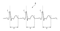
図32に示す第三実施形態の超音波診断装置1′においては、前記超音波プローブ2による圧迫とその弛緩によって生じた生体組織の変形による歪みではなく、心臓の拍動による生体組織の変形や、血管の脈動による血管周囲の生体組織の変形によって生じる歪みを算出して弾性画像EGを作成する。歪みの算出方法は、前記各実施形態と同様の相関演算を用いる。
In the ultrasonic
具体的構成について説明する。前記超音波診断装置1′は、基本的構成は上述の超音波診断装置1と同様であるものの、被検体の心拍を検出する心拍検出部11を備えている。また、前記物理量データ処理部5は、図10に示す物理量データ処理部5と同様に、前記物理量フレームデータ作成部51及びフレーム選択部52を有している。
A specific configuration will be described. The ultrasonic
本例の作用について説明する。本例では、心臓の拍動による生体組織の変形や血流による血管の脈動によって血管周囲の生体組織の変形が生じる部位に対し、前記超音波プローブ2によって超音波の走査を行なう。本例では、前記送受信部3は、一の走査面Pnにおいて、図33に示すように、一フレーム分のBモード画像用走査Bsと二フレーム分の弾性画像用走査ES1,ES2を一セットの走査として、これを複数セット分行なわせる。そして、前記送受信部3は、前記心拍検出部11で得られる図34に示す心電波形gに基づいて走査面の切替えを行なう。
The operation of this example will be described. In this example, ultrasonic scanning is performed by the
ここで、心電波形gに基づいて走査面を切り替えるタイミングについて詳しく説明する。生体組織の弾性をより正確に表す弾性画像を得るためには、前記超音波プローブ2によって走査を行なう部位が、心臓の拍動や血流による血管の脈動によって変形するタイミングで弾性画像用走査ES1,ES2が行なわれることが好ましい。従って、前記送受信部3は、このようなタイミングで弾性画像用走査ES1,ES2が行なわれた後に、走査面の切替えを行なう。例えば、頚動脈について前記超音波プローブ2による走査を行なう場合、前記心電波形gにおけるR波rから所定時間τ経過すると脈動によって生体組織が変形する。従って、前記送受信部3は、前記R波rから前記所定時間τ経過した時点以降の直後の二フレーム分の弾性画像用走査ES1,ES2が行なわれると、次の走査面P(n+1)についての走査を開始する。
Here, the timing for switching the scanning plane based on the electrocardiogram waveform g will be described in detail. In order to obtain an elastic image representing the elasticity of the living tissue more accurately, the elastic image scanning E is performed at a timing at which the portion scanned by the
前記フレーム選択部52は、R波rから所定時間τ経過した時点以降の直後の二フレーム分の弾性画像用走査ES1,ES2で得られたフレームデータFDe1,FDe2から作成される物理量フレームデータEFDを選択し、これを前記表示制御部6へ出力する。また、前記フレーム選択部52は、選択した物理量フレームデータEFDと対になるBモードフレームデータBFDを選択する。このBモードフレームデータBFDは、選択した物理量フレームデータEFDが得られた弾性画像用走査ES1,ES2とセットであるBモード画像用走査BSで得られたBモードフレームデータである。
The
前記フレーム選択部52によって選択されて前記表示制御部6へ出力されたBモードフレームデータBFD及び物理量フレームデータEFDは、前記メモリ61に記憶され、これらに基づいて作成された超音波画像Gが前記表示部7に表示される。
The B mode frame data BFD and the physical quantity frame data EFD selected by the
また、前記メモリ61には、前記フレーム選択部52によって選択されたBモードフレームデータBFD及び物理量フレームデータEFDが、各走査面Pについて記憶される。そして、本例では、各走査面PについてのBモードフレームデータBFD及び物理量フレームデータEFDに基づいて前記三次元画像や三次元の弾性画像が作成され表示される。
The
以上の超音波診断装置1′によれば、心拍情報を参照して、生体組織が変形するタイミングで弾性画像用走査ES1,ES2が行なわれた後に走査面を切り替えるようになっているので、生体組織の弾性をより正確に反映した物理量フレームデータEFDが得られた後に走査面が切り替わることになる。これにより、各走査面について生体組織の弾性をより正確に反映した弾性画像EGを得ることができる。
According to the ultrasonic
以上、本発明を前記各実施形態によって説明したが、本発明はその主旨を変更しない範囲で種々変更実施可能なことはもちろんである。例えば、本発明は、上述の実施形態のように機械的に三次元領域の走査を行なうものに限られるものではなく、電子的に三次元領域の走査を行なうものも含まれる。電子的な三次元領域の走査とは、前記第一方向aと前記第二方向b(図2参照)の両方向に電子的走査を行なう走査をいう。このように電子的に三次元領域の走査を行なう場合も、一の走査面Pnに複数フレーム分の走査(少なくとも一フレーム分のBモード画像用走査BSと二フレーム分の弾性画像用走査ES1,ES2)を行なう。 As mentioned above, although this invention was demonstrated by each said embodiment, of course, this invention can be variously implemented in the range which does not change the main point. For example, the present invention is not limited to the one that mechanically scans the three-dimensional region as in the above-described embodiment, and includes one that electronically scans the three-dimensional region. Electronic scanning of the three-dimensional region refers to scanning in which electronic scanning is performed in both the first direction a and the second direction b (see FIG. 2). Even when electronically scanning a three-dimensional region in this way, scanning for a plurality of frames on one scanning plane Pn (at least one frame for B-mode image scanning BS and two frames for elastic image scanning E). S 1, E S 2) perform.
また、前記物理量データ処理部5は、生体組織の弾性に関する物理量として、歪みの代わりに生体組織の変形による変位や弾性率などを算出してもよく、また他の公知の手法によって生体組織の弾性に関する物理量を算出してもよい。
In addition, the physical quantity
さらに、上記実施形態では、一フレーム分の超音波画像Gを得るために、一フレーム分のBモード画像用走査BSと二フレーム分の弾性画像用走査ES1,ES2とを行なうようになっているがこれに限られるものではない。例えば、二フレーム分の超音波の走査で得られたエコーデータに基づいて、一フレーム分の超音波画像Gを作成するようにしてもよい。この場合、二フレームのうちの一フレーム分の超音波の走査で得られたエコーデータに基づいて一フレームのBモード画像を作成し、また二フレーム分の超音波の走査で得られたエコーデータに基づいて物理量を算出して一フレームの弾性画像を作成する。 Furthermore, in the above embodiment, in order to obtain an ultrasonic image G of one frame, it performs a one frame for the B-mode image scanning B S and a secondary frame of elasticity image scanning E S 1, E S 2 However, it is not limited to this. For example, an ultrasonic image G for one frame may be created based on echo data obtained by scanning ultrasonic waves for two frames. In this case, a B-mode image of one frame is created based on echo data obtained by ultrasonic scanning for one frame out of two frames, and echo data obtained by ultrasonic scanning for two frames. A physical quantity is calculated based on the above to create an elastic image of one frame.
1 超音波診断装置
2 超音波プローブ
3 送受信部(走査制御部)
5 物理量データ作成部(弾性データ作成部)
7 表示部
8 制御部(走査制御部)
10 記憶部
11 心拍検出部
55 評価部
61 メモリ(記憶部)
521,533 相関係数平均部
522,551 物理量平均部
523,552 比算出部
524,554 乗算部
DESCRIPTION OF
5 Physical quantity data creation unit (elastic data creation unit)
7 Display section
8 Control unit (scanning control unit)
DESCRIPTION OF
521,533 Correlation coefficient averaging unit 522,551 Physical quantity averaging unit 523,552 Ratio calculation unit 524,554 Multiplication unit
Claims (15)
該超音波プローブに三次元領域を走査させる走査制御部であって、一の走査面について複数フレーム分の走査を行なわせる走査制御部と、
前記一の走査面における異なるフレームに属する同一音線上のエコーデータに基づいて、生体組織の各部における弾性に関する物理量を算出して、前記生体組織の弾性に関する弾性データを作成する弾性データ作成部と、
前記弾性データに基づいて作成された生体組織の弾性画像を表示する表示部と、
前記一の走査面における複数フレームの弾性データの中から、所定の評価指標に基づいて一フレーム選択するフレーム選択部と、
を備え、
前記フレーム選択部は、前記物理量の平均をフレーム毎に算出する物理量平均部と、該物理量平均部による算出値を、予め設定された前記物理量の平均の理想値と比較する比較部と、を有し、該比較部は、前記物理量平均部による算出値と前記物理量の平均の理想値との比を算出し、前記フレーム選択部は、前記比に基づいてフレームの選択を行なう
ことを特徴とする超音波診断装置。 An ultrasound probe for scanning ultrasound; and
A scanning control unit that causes the ultrasonic probe to scan a three-dimensional region, and a scanning control unit that performs scanning for a plurality of frames on one scanning plane;
Based on echo data on the same sound line belonging to different frames on the one scanning plane, a physical quantity relating to elasticity in each part of the living tissue is calculated, and an elasticity data creating unit for creating elasticity data relating to the elasticity of the living tissue;
A display unit for displaying an elasticity image of the living tissue created based on the elasticity data;
A frame selection unit that selects one frame based on a predetermined evaluation index from a plurality of frames of elasticity data on the one scanning plane;
With
The frame selection unit includes a physical quantity averaging unit that calculates an average of the physical quantities for each frame, and a comparison unit that compares a value calculated by the physical quantity averaging unit with a preset ideal ideal value of the physical quantities. The comparison unit calculates a ratio between a value calculated by the physical quantity averaging unit and an average ideal value of the physical quantities, and the frame selection unit performs frame selection based on the ratio. Ultrasound diagnostic device.
該超音波プローブに三次元領域を走査させる走査制御部であって、一の走査面について複数フレーム分の走査を行なわせる走査制御部と、
前記一の走査面における異なるフレームに属する同一音線上のエコーデータに基づいて、生体組織の弾性に関する弾性データを作成する弾性データ作成部と、
前記弾性データに基づいて作成された生体組織の弾性画像を表示する表示部と、
前記一の走査面における複数フレームの弾性データの中から、所定の評価指標に基づいて一フレーム選択するフレーム選択部と、
を備え、
前記弾性データ作成部は、前記一の走査面における同一音線上の時間的に異なるエコーデータに相関ウィンドウを設定し、該相関ウィンドウ間で相関演算を行なって生体組織の各部における弾性に関する物理量を算出して前記弾性データの作成を行なうものであり、
前記フレーム選択部は、所定の閾値以上の相関係数の相関演算が行なわれた相関ウィンドウについて得られた物理量の平均をフレーム毎に算出する物理量平均部と、予め設定された物理量の平均の理想値に対する前記物理量平均部による算出値の比を算出する比算出部と、前記相関ウィンドウ間の相関演算における相関係数の平均をフレーム毎に算出する相関係数平均部と、前記比算出部の算出値と、前記相関係数平均部の算出値とを乗算する乗算部と、を有し、該乗算部の乗算結果を評価指標としてフレームの選択を行なう
ことを特徴とする超音波診断装置。 An ultrasound probe for scanning ultrasound; and
A scanning control unit that causes the ultrasonic probe to scan a three-dimensional region, and a scanning control unit that performs scanning for a plurality of frames on one scanning plane;
Based on echo data on the same sound ray belonging to different frames on the one scanning plane, an elasticity data creation unit that creates elasticity data relating to the elasticity of the living tissue;
A display unit for displaying an elasticity image of the living tissue created based on the elasticity data;
A frame selection unit that selects one frame based on a predetermined evaluation index from a plurality of frames of elasticity data on the one scanning plane;
With
The elasticity data creation unit sets a correlation window for temporally different echo data on the same sound ray on the one scanning plane, and performs a correlation operation between the correlation windows to calculate a physical quantity related to elasticity in each part of the living tissue. And creating the elasticity data,
The frame selection unit includes: a physical quantity averaging unit that calculates an average of physical quantities obtained for each correlation window in which a correlation calculation of a correlation coefficient equal to or greater than a predetermined threshold is performed; and an ideal of an average of preset physical quantities A ratio calculation unit that calculates a ratio of values calculated by the physical quantity average unit with respect to a value, a correlation coefficient average unit that calculates an average of correlation coefficients in the correlation calculation between the correlation windows, and a ratio calculation unit An ultrasound diagnostic apparatus , comprising: a multiplication unit that multiplies the calculated value and the calculated value of the correlation coefficient averaging unit, and performs frame selection using the multiplication result of the multiplication unit as an evaluation index .
該超音波プローブに三次元領域を走査させる走査制御部であって、一の走査面について複数フレーム分の走査を行なわせる走査制御部と、
前記一の走査面における異なるフレームに属する同一音線上のエコーデータに基づいて、生体組織の弾性に関する弾性データを作成する弾性データ作成部と、
前記弾性データに基づいて作成された生体組織の弾性画像を表示する表示部と、
を備え、
前弾性データ作成部は、一の走査面について得られた複数フレームの弾性データのうち、一のフレームの弾性データにおけるエラー画素のデータを、他のフレームの弾性データにおける非エラー画素のデータに置換して置換済弾性データを作成する置換済弾性データ作成部を有しており、
前記表示部に表示される弾性画像は、前記置換済弾性データに基づく弾性画像である
ことを特徴とする超音波診断装置。 An ultrasound probe for scanning ultrasound; and
A scanning control unit that causes the ultrasonic probe to scan a three-dimensional region, and a scanning control unit that performs scanning for a plurality of frames on one scanning plane;
Based on echo data on the same sound ray belonging to different frames on the one scanning plane, an elasticity data creation unit that creates elasticity data relating to the elasticity of the living tissue;
A display unit for displaying an elasticity image of the living tissue created based on the elasticity data;
Equipped with a,
The pre-elasticity data creation unit replaces the error pixel data in the elasticity data of one frame with the non-error pixel data in the elasticity data of other frames among the elasticity data of multiple frames obtained for one scanning plane. And having a replaced elasticity data creation unit for creating replaced elasticity data,
The ultrasound diagnostic apparatus , wherein the elasticity image displayed on the display unit is an elasticity image based on the replaced elasticity data .
該超音波プローブに三次元領域を走査させる走査制御部であって、一の走査面について複数フレーム分の走査を行なわせる走査制御部と、
前記一の走査面における異なるフレームに属する同一音線上のエコーデータに基づいて、生体組織の弾性に関する弾性データを作成する弾性データ作成部と、
前記弾性データに基づいて作成された生体組織の弾性画像を表示する表示部と、
前記一の走査面について得られた前記弾性データについて、所定の評価指標に基づいて、所定の画質の弾性画像が得られる弾性データであるか否かの評価を行なう評価部と、
を備え、
前記走査制御部は、前記一の走査面についての弾性データについて、前記評価部によって所定の画質の弾性画像が得られる弾性データであると評価された場合に、前記一の走査面から他の走査面に走査面を切り替える
ことを特徴とする超音波診断装置。 An ultrasound probe for scanning ultrasound; and
A scanning control unit that causes the ultrasonic probe to scan a three-dimensional region, and a scanning control unit that performs scanning for a plurality of frames on one scanning plane;
Based on echo data on the same sound ray belonging to different frames on the one scanning plane, an elasticity data creation unit that creates elasticity data relating to the elasticity of the living tissue;
A display unit for displaying an elasticity image of the living tissue created based on the elasticity data;
An evaluation unit that evaluates whether or not the elasticity data obtained for the one scanning plane is elasticity data for obtaining an elasticity image of a predetermined image quality based on a predetermined evaluation index;
With
The scanning control unit, when the elasticity data for the one scanning plane is evaluated as the elasticity data by which the elasticity image of a predetermined image quality is obtained by the evaluation unit, the other scanning from the one scanning plane. An ultrasonic diagnostic apparatus characterized by switching a scanning plane to a plane .
ことを特徴とする請求項6に記載の超音波診断装置。 The evaluation section evaluates whether or not the elasticity data is an elasticity image from which an elasticity image of a predetermined image quality is obtained based on the number of error pixels in one frame of the elasticity data as the evaluation index. 6. The ultrasonic diagnostic apparatus according to 6 .
前記評価部は、前記評価指標として、前記相関演算で得られた相関係数の平均をフレーム毎に算出し、該相関係数の平均に基づいて、所定の画質の弾性画像が得られる弾性データであるか否かの評価を行なうことを特徴とする請求項6に記載の超音波診断装置。 The elasticity data creation unit sets a correlation window for temporally different echo data on the same sound ray on the one scanning plane, and performs a correlation operation between the correlation windows to calculate a physical quantity related to elasticity in each part of the living tissue. And creating the elasticity data,
The evaluation unit calculates, as the evaluation index, an average of correlation coefficients obtained by the correlation calculation for each frame, and based on the average of the correlation coefficients, elasticity data from which an elasticity image of a predetermined image quality is obtained The ultrasonic diagnostic apparatus according to claim 6 , wherein an evaluation is performed to determine whether or not
前記評価部は、前記物理量の平均をフレーム毎に算出する物理量平均部と、該物理量平均部による算出値を、予め設定された前記物理量の平均値と比較する比較部と、を有し、該比較部の比較結果を評価指標として、所定の画質の弾性画像が得られる弾性データであるか否かの評価を行なう
ことを特徴とする請求項6に記載の超音波診断装置。 The elasticity data creation unit sets a correlation window for temporally different echo data on the same sound ray on the one scanning plane, and performs a correlation operation between the correlation windows to calculate a physical quantity related to elasticity in each part of the living tissue. And creating the elasticity data,
The evaluation unit includes a physical quantity average unit that calculates an average of the physical quantity for each frame, and a comparison unit that compares a calculated value by the physical quantity average unit with a preset average value of the physical quantity, The ultrasonic diagnostic apparatus according to claim 6 , wherein the comparison result of the comparison unit is used as an evaluation index to evaluate whether or not the elasticity data is an elastic image having a predetermined image quality.
前記評価部は、所定の閾値以上の相関係数の相関演算が行なわれた相関ウィンドウについて得られた物理量の平均をフレーム毎に算出する物理量平均部と、予め設定された物理量の平均値に対する前記物理量平均部による算出値の比を算出する比算出部と、前記相関ウィンドウ間の相関演算における相関係数の平均をフレーム毎に算出する相関係数平均部と、前記比算出部の算出値と、前記相関係数平均部の算出値とを乗算する乗算部と、を有し、該乗算部の乗算結果を評価指標として、所定の画質の弾性画像が得られる弾性データであるか否かの評価を行なう
ことを特徴とする請求項6に記載の超音波診断装置。 The elasticity data creation unit sets a correlation window for temporally different echo data on the same sound ray on the one scanning plane, and performs a correlation operation between the correlation windows to calculate a physical quantity related to elasticity in each part of the living tissue. And creating the elasticity data,
The evaluation unit includes: a physical quantity averaging unit that calculates an average of physical quantities obtained for each correlation window in which a correlation calculation of a correlation coefficient equal to or greater than a predetermined threshold is performed; and the average for the preset physical quantity A ratio calculation unit that calculates a ratio of calculated values by the physical quantity averaging unit, a correlation coefficient average unit that calculates an average of correlation coefficients in the correlation calculation between the correlation windows for each frame, and a calculated value of the ratio calculation unit; And a multiplier that multiplies the calculated value of the correlation coefficient averaging unit, and whether or not the elasticity data is an elastic data that provides an elastic image of a predetermined image quality using the multiplication result of the multiplier as an evaluation index. The ultrasonic diagnostic apparatus according to claim 6 , wherein evaluation is performed.
前記評価部は、一のフレームにおける前記正負の符合の割合を前記評価指標として所定の画質の弾性画像が得られる弾性データであるか否かの評価を行なう
ことを特徴とする請求項6に記載の超音波診断装置。 The elasticity data creation unit sets correlation windows for temporally different echo data on the same sound ray on the one scanning plane, performs a correlation calculation between the correlation windows, and calculates a physical quantity related to elasticity in each part of the living tissue. The elasticity data is created by calculating with the sign of
7. The evaluation unit according to claim 6 , wherein the evaluation unit evaluates whether or not the data is elasticity data from which an elastic image having a predetermined image quality is obtained using the ratio of the positive and negative signs in one frame as the evaluation index. Ultrasound diagnostic equipment.
前記評価部は、前記弾性データの一フレームにおける画素毎の前記物理量の合計を前記評価指標として所定の画質の弾性画像が得られる弾性データであるか否かの評価を行なう
ことを特徴とする請求項6に記載の超音波診断装置。 The elasticity data creation unit calculates the physical quantity related to the elasticity of the living tissue for each pixel, creates the elasticity data,
The evaluation unit evaluates whether or not the elasticity data is an elasticity data from which an elasticity image of a predetermined image quality is obtained using the sum of the physical quantities for each pixel in one frame of the elasticity data as the evaluation index. Item 7. The ultrasonic diagnostic apparatus according to Item 6 .
前記評価部は、前記弾性データの一フレームにおける画素毎の前記物理量の平均を評価指標として、所定の画質の弾性画像が得られる弾性データであるか否かの評価を行なう
ことを特徴とする請求項6に記載の超音波診断装置。 The elasticity data creation unit calculates the physical quantity related to the elasticity of the living tissue for each pixel, creates the elasticity data,
The evaluation unit evaluates whether or not the elasticity data is an elasticity data from which an elasticity image of a predetermined image quality is obtained, using an average of the physical quantities for each pixel in one frame of the elasticity data as an evaluation index. Item 7. The ultrasonic diagnostic apparatus according to Item 6 .
前記走査制御部は、一の走査面で前記機械的走査を停止して、前記配列方向に超音波の走査を行なって複数フレーム分の走査を行なうよう前記超音波プローブを制御する
ことを特徴とする請求項1〜13のいずれか一項に記載の超音波診断装置。 The ultrasonic probe is a mechanical 3D probe that performs electronic scanning in an arrangement direction of ultrasonic transducers and performs mechanical scanning in a direction orthogonal to the arrangement direction.
The scanning control unit controls the ultrasonic probe so as to stop the mechanical scanning on one scanning plane, perform ultrasonic scanning in the arrangement direction, and perform scanning for a plurality of frames. The ultrasonic diagnostic apparatus according to any one of claims 1 to 13 .
前記走査制御部は、一の走査面で前記配列方向に超音波の走査を行なって複数フレーム分の走査をさせる
ことを特徴とする請求項1〜13のいずれか一項に記載の超音波診断装置。 The ultrasonic probe is an ultrasonic probe that performs electronic scanning in a direction perpendicular to the arrangement direction of the ultrasonic transducers and the arrangement direction,
The ultrasonic diagnosis according to any one of claims 1 to 13, wherein the scanning control unit scans a plurality of frames by performing ultrasonic scanning in the arrangement direction on one scanning plane. apparatus.
Priority Applications (3)
| Application Number | Priority Date | Filing Date | Title |
|---|---|---|---|
| JP2010058891A JP5677757B2 (en) | 2010-03-16 | 2010-03-16 | Ultrasonic diagnostic equipment |
| KR1020110023113A KR101593719B1 (en) | 2010-03-16 | 2011-03-16 | Ultrasonic diagnosis device |
| KR1020150167132A KR101666324B1 (en) | 2010-03-16 | 2015-11-27 | Ultrasonic diagnosis device |
Applications Claiming Priority (1)
| Application Number | Priority Date | Filing Date | Title |
|---|---|---|---|
| JP2010058891A JP5677757B2 (en) | 2010-03-16 | 2010-03-16 | Ultrasonic diagnostic equipment |
Publications (2)
| Publication Number | Publication Date |
|---|---|
| JP2011189042A JP2011189042A (en) | 2011-09-29 |
| JP5677757B2 true JP5677757B2 (en) | 2015-02-25 |
Family
ID=44794598
Family Applications (1)
| Application Number | Title | Priority Date | Filing Date |
|---|---|---|---|
| JP2010058891A Active JP5677757B2 (en) | 2010-03-16 | 2010-03-16 | Ultrasonic diagnostic equipment |
Country Status (2)
| Country | Link |
|---|---|
| JP (1) | JP5677757B2 (en) |
| KR (2) | KR101593719B1 (en) |
Families Citing this family (6)
| Publication number | Priority date | Publication date | Assignee | Title |
|---|---|---|---|---|
| US9392995B2 (en) * | 2012-07-25 | 2016-07-19 | General Electric Company | Ultrasound imaging system and method |
| JP5774560B2 (en) * | 2012-08-20 | 2015-09-09 | ジーイー・メディカル・システムズ・グローバル・テクノロジー・カンパニー・エルエルシー | Ultrasonic diagnostic apparatus and control program therefor |
| JP5622985B1 (en) * | 2013-01-18 | 2014-11-12 | オリンパスメディカルシステムズ株式会社 | Ultrasonic observation system |
| US8824752B1 (en) | 2013-03-15 | 2014-09-02 | Heartflow, Inc. | Methods and systems for assessing image quality in modeling of patient anatomic or blood flow characteristics |
| KR102186096B1 (en) * | 2013-07-01 | 2020-12-03 | 한국전자통신연구원 | Apparatus of ultrasound scanning assistance for breast cancer diagnosis and method of ultrasound scanning |
| FR3078484A1 (en) * | 2018-03-02 | 2019-09-06 | Echosens | METHOD FOR MEASURING A GUIDED ULTRASONIC ATTENUATION PARAMETER BY HARMONIC ELASTOGRAPHY, PROBE AND DEVICE FOR IMPLEMENTING THE METHOD |
Family Cites Families (13)
| Publication number | Priority date | Publication date | Assignee | Title |
|---|---|---|---|---|
| JP3537594B2 (en) * | 1996-06-13 | 2004-06-14 | アロカ株式会社 | Ultrasonic diagnostic equipment |
| JP4455003B2 (en) * | 2003-10-14 | 2010-04-21 | 株式会社日立メディコ | Ultrasonic diagnostic equipment |
| JP4368185B2 (en) * | 2003-11-27 | 2009-11-18 | 株式会社日立メディコ | Ultrasonic diagnostic equipment |
| EP1782736B1 (en) * | 2004-08-25 | 2012-06-06 | Hitachi Medical Corporation | Ultrasonographic device |
| JP4694930B2 (en) * | 2005-09-21 | 2011-06-08 | 富士フイルム株式会社 | Ultrasonic diagnostic equipment |
| JP4817374B2 (en) * | 2006-05-25 | 2011-11-16 | 株式会社日立メディコ | Ultrasonic diagnostic equipment |
| JP4898809B2 (en) * | 2006-07-18 | 2012-03-21 | 株式会社日立メディコ | Ultrasonic diagnostic equipment |
| KR100908248B1 (en) * | 2006-09-13 | 2009-07-20 | 주식회사 메디슨 | Elastic video display method |
| JP5415669B2 (en) * | 2006-09-25 | 2014-02-12 | 株式会社日立メディコ | Ultrasonic diagnostic equipment |
| US8100831B2 (en) * | 2006-11-22 | 2012-01-24 | General Electric Company | Direct strain estimator for measuring elastic properties of tissue |
| JP4889540B2 (en) * | 2007-03-28 | 2012-03-07 | 株式会社日立メディコ | Ultrasonic diagnostic equipment |
| JP5371199B2 (en) * | 2007-04-10 | 2013-12-18 | 株式会社日立メディコ | Ultrasonic diagnostic equipment |
| JP5264097B2 (en) * | 2007-04-11 | 2013-08-14 | 株式会社日立メディコ | Ultrasonic diagnostic equipment |
-
2010
- 2010-03-16 JP JP2010058891A patent/JP5677757B2/en active Active
-
2011
- 2011-03-16 KR KR1020110023113A patent/KR101593719B1/en active Active
-
2015
- 2015-11-27 KR KR1020150167132A patent/KR101666324B1/en not_active Expired - Fee Related
Also Published As
| Publication number | Publication date |
|---|---|
| JP2011189042A (en) | 2011-09-29 |
| KR101593719B1 (en) | 2016-02-15 |
| KR101666324B1 (en) | 2016-10-13 |
| KR20150140611A (en) | 2015-12-16 |
| KR20110104451A (en) | 2011-09-22 |
Similar Documents
| Publication | Publication Date | Title |
|---|---|---|
| JP5484826B2 (en) | Ultrasonic diagnostic equipment | |
| JP4455003B2 (en) | Ultrasonic diagnostic equipment | |
| EP1554982A1 (en) | Ultrasonographic device | |
| KR101666324B1 (en) | Ultrasonic diagnosis device | |
| JP5186389B2 (en) | Ultrasonic diagnostic equipment | |
| WO2004062503A1 (en) | Ultrasonographic device | |
| JP5770175B2 (en) | Ultrasonic diagnostic apparatus and ultrasonic transmission / reception method | |
| JPWO2010026823A1 (en) | Ultrasonic diagnostic apparatus and ultrasonic image display method | |
| JP5356140B2 (en) | Ultrasonic diagnostic apparatus and control program therefor | |
| JP2012061075A (en) | Ultrasonic diagnostic apparatus and control program of the same | |
| JP5473527B2 (en) | Ultrasonic diagnostic equipment | |
| JP5489178B2 (en) | Ultrasonic diagnostic equipment | |
| KR101329944B1 (en) | Ultrasonic diagnosis device | |
| JP5623609B2 (en) | Ultrasonic diagnostic equipment | |
| KR101574851B1 (en) | Ultrasonic diagnosis apparatus and program for controlling the same | |
| JP5535574B2 (en) | Ultrasonic diagnostic equipment | |
| JP5656389B2 (en) | Ultrasound system for adaptive persistence processing of elastic images | |
| JP5743311B2 (en) | Ultrasonic diagnostic equipment | |
| JP5485418B2 (en) | Ultrasonic diagnostic equipment | |
| KR101574821B1 (en) | Ultrasonic diagnosis apparatus and program for controlling the same | |
| KR20130014671A (en) | Ultrasound diagnostic apparatus and method thereof | |
| JP2012192075A (en) | Ultrasound diagnostic apparatus and ultrasound image generation method | |
| JP5449896B2 (en) | Ultrasonic diagnostic equipment | |
| JP2011024758A (en) | Ultrasonic diagnostic apparatus, medical image processing unit, and medical image processing program |
Legal Events
| Date | Code | Title | Description |
|---|---|---|---|
| A625 | Written request for application examination (by other person) |
Free format text: JAPANESE INTERMEDIATE CODE: A625 Effective date: 20130205 |
|
| A977 | Report on retrieval |
Free format text: JAPANESE INTERMEDIATE CODE: A971007 Effective date: 20140130 |
|
| A131 | Notification of reasons for refusal |
Free format text: JAPANESE INTERMEDIATE CODE: A131 Effective date: 20140224 |
|
| A521 | Request for written amendment filed |
Free format text: JAPANESE INTERMEDIATE CODE: A523 Effective date: 20140526 |
|
| TRDD | Decision of grant or rejection written | ||
| A01 | Written decision to grant a patent or to grant a registration (utility model) |
Free format text: JAPANESE INTERMEDIATE CODE: A01 Effective date: 20141208 |
|
| A61 | First payment of annual fees (during grant procedure) |
Free format text: JAPANESE INTERMEDIATE CODE: A61 Effective date: 20150105 |
|
| R150 | Certificate of patent or registration of utility model |
Ref document number: 5677757 Country of ref document: JP Free format text: JAPANESE INTERMEDIATE CODE: R150 |
|
| R250 | Receipt of annual fees |
Free format text: JAPANESE INTERMEDIATE CODE: R250 |
|
| R250 | Receipt of annual fees |
Free format text: JAPANESE INTERMEDIATE CODE: R250 |
|
| R250 | Receipt of annual fees |
Free format text: JAPANESE INTERMEDIATE CODE: R250 |
|
| R250 | Receipt of annual fees |
Free format text: JAPANESE INTERMEDIATE CODE: R250 |
|
| R250 | Receipt of annual fees |
Free format text: JAPANESE INTERMEDIATE CODE: R250 |
|
| R250 | Receipt of annual fees |
Free format text: JAPANESE INTERMEDIATE CODE: R250 |
|
| R250 | Receipt of annual fees |
Free format text: JAPANESE INTERMEDIATE CODE: R250 |
|
| R250 | Receipt of annual fees |
Free format text: JAPANESE INTERMEDIATE CODE: R250 |