JP5675673B2 - Fiber reinforced plastic heating element and wind power generator equipped with the heating element - Google Patents
Fiber reinforced plastic heating element and wind power generator equipped with the heating elementInfo
- Publication number
- JP5675673B2 JP5675673B2 JP2012042922A JP2012042922A JP5675673B2 JP 5675673 B2 JP5675673 B2 JP 5675673B2 JP 2012042922 A JP2012042922 A JP 2012042922A JP 2012042922 A JP2012042922 A JP 2012042922A JP 5675673 B2 JP5675673 B2 JP 5675673B2
- Authority
- JP
- Japan
- Prior art keywords
- layer
- reinforced plastic
- heating element
- fiber
- cfrp
- Prior art date
- Legal status (The legal status is an assumption and is not a legal conclusion. Google has not performed a legal analysis and makes no representation as to the accuracy of the status listed.)
- Active
Links
Images

Classifications
-
- B—PERFORMING OPERATIONS; TRANSPORTING
- B32—LAYERED PRODUCTS
- B32B—LAYERED PRODUCTS, i.e. PRODUCTS BUILT-UP OF STRATA OF FLAT OR NON-FLAT, e.g. CELLULAR OR HONEYCOMB, FORM
- B32B15/00—Layered products comprising a layer of metal
- B32B15/14—Layered products comprising a layer of metal next to a fibrous or filamentary layer
-
- B—PERFORMING OPERATIONS; TRANSPORTING
- B32—LAYERED PRODUCTS
- B32B—LAYERED PRODUCTS, i.e. PRODUCTS BUILT-UP OF STRATA OF FLAT OR NON-FLAT, e.g. CELLULAR OR HONEYCOMB, FORM
- B32B5/00—Layered products characterised by the non- homogeneity or physical structure, i.e. comprising a fibrous, filamentary, particulate or foam layer; Layered products characterised by having a layer differing constitutionally or physically in different parts
- B32B5/22—Layered products characterised by the non- homogeneity or physical structure, i.e. comprising a fibrous, filamentary, particulate or foam layer; Layered products characterised by having a layer differing constitutionally or physically in different parts characterised by the presence of two or more layers which are next to each other and are fibrous, filamentary, formed of particles or foamed
- B32B5/24—Layered products characterised by the non- homogeneity or physical structure, i.e. comprising a fibrous, filamentary, particulate or foam layer; Layered products characterised by having a layer differing constitutionally or physically in different parts characterised by the presence of two or more layers which are next to each other and are fibrous, filamentary, formed of particles or foamed one layer being a fibrous or filamentary layer
- B32B5/26—Layered products characterised by the non- homogeneity or physical structure, i.e. comprising a fibrous, filamentary, particulate or foam layer; Layered products characterised by having a layer differing constitutionally or physically in different parts characterised by the presence of two or more layers which are next to each other and are fibrous, filamentary, formed of particles or foamed one layer being a fibrous or filamentary layer another layer next to it also being fibrous or filamentary
-
- F—MECHANICAL ENGINEERING; LIGHTING; HEATING; WEAPONS; BLASTING
- F03—MACHINES OR ENGINES FOR LIQUIDS; WIND, SPRING, OR WEIGHT MOTORS; PRODUCING MECHANICAL POWER OR A REACTIVE PROPULSIVE THRUST, NOT OTHERWISE PROVIDED FOR
- F03D—WIND MOTORS
- F03D1/00—Wind motors with rotation axis substantially parallel to the air flow entering the rotor
- F03D1/06—Rotors
- F03D1/065—Rotors characterised by their construction elements
- F03D1/0675—Rotors characterised by their construction elements of the blades
-
- F—MECHANICAL ENGINEERING; LIGHTING; HEATING; WEAPONS; BLASTING
- F03—MACHINES OR ENGINES FOR LIQUIDS; WIND, SPRING, OR WEIGHT MOTORS; PRODUCING MECHANICAL POWER OR A REACTIVE PROPULSIVE THRUST, NOT OTHERWISE PROVIDED FOR
- F03D—WIND MOTORS
- F03D80/00—Details, components or accessories not provided for in groups F03D1/00 - F03D17/00
- F03D80/40—Ice detection; De-icing means
-
- H—ELECTRICITY
- H05—ELECTRIC TECHNIQUES NOT OTHERWISE PROVIDED FOR
- H05B—ELECTRIC HEATING; ELECTRIC LIGHT SOURCES NOT OTHERWISE PROVIDED FOR; CIRCUIT ARRANGEMENTS FOR ELECTRIC LIGHT SOURCES, IN GENERAL
- H05B3/00—Ohmic-resistance heating
- H05B3/10—Heating elements characterised by the composition or nature of the materials or by the arrangement of the conductor
- H05B3/12—Heating elements characterised by the composition or nature of the materials or by the arrangement of the conductor characterised by the composition or nature of the conductive material
- H05B3/14—Heating elements characterised by the composition or nature of the materials or by the arrangement of the conductor characterised by the composition or nature of the conductive material the material being non-metallic
- H05B3/145—Carbon only, e.g. carbon black, graphite
-
- H—ELECTRICITY
- H05—ELECTRIC TECHNIQUES NOT OTHERWISE PROVIDED FOR
- H05B—ELECTRIC HEATING; ELECTRIC LIGHT SOURCES NOT OTHERWISE PROVIDED FOR; CIRCUIT ARRANGEMENTS FOR ELECTRIC LIGHT SOURCES, IN GENERAL
- H05B3/00—Ohmic-resistance heating
- H05B3/40—Heating elements having the shape of rods or tubes
- H05B3/42—Heating elements having the shape of rods or tubes non-flexible
- H05B3/44—Heating elements having the shape of rods or tubes non-flexible heating conductor arranged within rods or tubes of insulating material
-
- B—PERFORMING OPERATIONS; TRANSPORTING
- B32—LAYERED PRODUCTS
- B32B—LAYERED PRODUCTS, i.e. PRODUCTS BUILT-UP OF STRATA OF FLAT OR NON-FLAT, e.g. CELLULAR OR HONEYCOMB, FORM
- B32B2260/00—Layered product comprising an impregnated, embedded, or bonded layer wherein the layer comprises an impregnation, embedding, or binder material
- B32B2260/02—Composition of the impregnated, bonded or embedded layer
- B32B2260/021—Fibrous or filamentary layer
- B32B2260/023—Two or more layers
-
- B—PERFORMING OPERATIONS; TRANSPORTING
- B32—LAYERED PRODUCTS
- B32B—LAYERED PRODUCTS, i.e. PRODUCTS BUILT-UP OF STRATA OF FLAT OR NON-FLAT, e.g. CELLULAR OR HONEYCOMB, FORM
- B32B2262/00—Composition or structural features of fibres which form a fibrous or filamentary layer or are present as additives
- B32B2262/10—Inorganic fibres
- B32B2262/101—Glass fibres
-
- B—PERFORMING OPERATIONS; TRANSPORTING
- B32—LAYERED PRODUCTS
- B32B—LAYERED PRODUCTS, i.e. PRODUCTS BUILT-UP OF STRATA OF FLAT OR NON-FLAT, e.g. CELLULAR OR HONEYCOMB, FORM
- B32B2262/00—Composition or structural features of fibres which form a fibrous or filamentary layer or are present as additives
- B32B2262/10—Inorganic fibres
- B32B2262/106—Carbon fibres, e.g. graphite fibres
-
- H—ELECTRICITY
- H05—ELECTRIC TECHNIQUES NOT OTHERWISE PROVIDED FOR
- H05B—ELECTRIC HEATING; ELECTRIC LIGHT SOURCES NOT OTHERWISE PROVIDED FOR; CIRCUIT ARRANGEMENTS FOR ELECTRIC LIGHT SOURCES, IN GENERAL
- H05B2203/00—Aspects relating to Ohmic resistive heating covered by group H05B3/00
- H05B2203/011—Heaters using laterally extending conductive material as connecting means
-
- H—ELECTRICITY
- H05—ELECTRIC TECHNIQUES NOT OTHERWISE PROVIDED FOR
- H05B—ELECTRIC HEATING; ELECTRIC LIGHT SOURCES NOT OTHERWISE PROVIDED FOR; CIRCUIT ARRANGEMENTS FOR ELECTRIC LIGHT SOURCES, IN GENERAL
- H05B2203/00—Aspects relating to Ohmic resistive heating covered by group H05B3/00
- H05B2203/016—Heaters using particular connecting means
-
- H—ELECTRICITY
- H05—ELECTRIC TECHNIQUES NOT OTHERWISE PROVIDED FOR
- H05B—ELECTRIC HEATING; ELECTRIC LIGHT SOURCES NOT OTHERWISE PROVIDED FOR; CIRCUIT ARRANGEMENTS FOR ELECTRIC LIGHT SOURCES, IN GENERAL
- H05B2214/00—Aspects relating to resistive heating, induction heating and heating using microwaves, covered by groups H05B3/00, H05B6/00
- H05B2214/02—Heaters specially designed for de-icing or protection against icing
-
- Y—GENERAL TAGGING OF NEW TECHNOLOGICAL DEVELOPMENTS; GENERAL TAGGING OF CROSS-SECTIONAL TECHNOLOGIES SPANNING OVER SEVERAL SECTIONS OF THE IPC; TECHNICAL SUBJECTS COVERED BY FORMER USPC CROSS-REFERENCE ART COLLECTIONS [XRACs] AND DIGESTS
- Y02—TECHNOLOGIES OR APPLICATIONS FOR MITIGATION OR ADAPTATION AGAINST CLIMATE CHANGE
- Y02E—REDUCTION OF GREENHOUSE GAS [GHG] EMISSIONS, RELATED TO ENERGY GENERATION, TRANSMISSION OR DISTRIBUTION
- Y02E10/00—Energy generation through renewable energy sources
- Y02E10/70—Wind energy
- Y02E10/72—Wind turbines with rotation axis in wind direction
Landscapes
- Engineering & Computer Science (AREA)
- Life Sciences & Earth Sciences (AREA)
- Sustainable Development (AREA)
- Sustainable Energy (AREA)
- Chemical & Material Sciences (AREA)
- Combustion & Propulsion (AREA)
- Mechanical Engineering (AREA)
- General Engineering & Computer Science (AREA)
- Wind Motors (AREA)
- Surface Heating Bodies (AREA)
- Control Of Resistance Heating (AREA)
- Resistance Heating (AREA)
Description
本発明は、強化繊維を含む樹脂系複合材に発熱源を組み込んだ繊維強化プラスチック発熱体に関し、特に、ブレードへの着氷防止および脱氷の機能を有する繊維強化プラスチック発熱体を備えた風力発電装置に関する。 The present invention relates to a fiber reinforced plastic heating element in which a heat source is incorporated into a resin composite material containing reinforcing fibers, and in particular, wind power generation provided with a fiber reinforced plastic heating element that has a function of preventing icing on a blade and de-icing. Relates to the device.
風力発電装置のブレードや航空機の主翼等の自然環境下で使用される構造体は外気に晒されるので、寒冷の場合、降雪や降氷雨時などに着氷することがある。さらに着氷した氷が成長すると、構造体の重量が増加したり、あるいは風力発電装置のブレードや航空機の主翼においては空気抵抗の増加や揚力減少等を招くことから、運転が適性に実施されないことが懸念される。 Since structures used in a natural environment such as blades of wind power generators and main wings of aircraft are exposed to the outside air, in the case of cold, they may be icing during snowfall or icy rain. Further, when the icing ice grows, the weight of the structure increases, or the blades of the wind power generator and the main wing of the aircraft cause an increase in air resistance and a decrease in lift. Is concerned.
こういった着氷が問題となる装置の一つとして、風力発電装置が挙げられる。風力発電装置は、タワーの上部にナセルが支持され、複数のブレードが取り付けられたハブがナセルに回転自在に支持された構成を有する。そして、風力発電装置では、風の運動エネルギーをブレードの回転エネルギーに変換し、さらにこの回転エネルギーを発電機にて電力に変換するようになっている。近年、風力発電装置は、発電効率の向上を目的として大型化が進められている。これに伴ってブレードも長大化しつつあり、その表面積も大きくなることから着氷の影響も大きくなる。したがって、ブレードを始めとした構造体において着氷防止および脱氷可能な構成が求められている。 One of the devices in which such icing is a problem is a wind power generator. The wind power generator has a configuration in which a nacelle is supported on an upper portion of a tower and a hub to which a plurality of blades are attached is rotatably supported by the nacelle. And in a wind power generator, the kinetic energy of a wind is converted into the rotational energy of a braid | blade, and also this rotational energy is converted into electric power with a generator. In recent years, wind turbine generators have been increased in size for the purpose of improving power generation efficiency. Along with this, the blades are becoming longer and the surface area of the blades is increased, so that the influence of icing is also increased. Therefore, a structure capable of preventing icing and deicing is required in a structure including a blade.
例えば、特許文献1には、回転機器のブレードを加熱する複数の加熱手段を有する着氷防止装置が記載されている。加熱手段としてはヒータが用いられ、光ファイバで着氷物の位置を特定し、ヒータで氷を加熱することにより脱氷あるいは着氷を抑制している。
For example,
また、特許文献2には、航空機の前縁部等の構造体の外表面において、よどみ点となる特定部分を含む外表面範囲に亘ってナノ構造のピンが多数配列されるとともに、外表面にエネルギ付与手段によってエネルギを付与する防除氷装置が記載されている。エネルギ付与手段としては、ヒータやパルス発生器が記載されている。ナノ構造のピンによって、過冷却水が付着せずに後方に流れていくので、よどみ点以外の部分は着氷を防止でき、さらにその他の部分はエネルギ付与手段によって脱氷することができる。
Further, in
さらに、特許文献3には、複合材からなる複合材部と、導電体からなる導電体部とを備えた複合材製構造体が記載されている。導電体部は、航空機における防除氷の機能を得るための部分であるとともに、製造時には成形および組立の少なくとも一方のために発熱体として機能する。
Further,
上記したように、従来から着氷防止および脱氷を目的として、構造体に加熱源を設ける構成は種々提案されている。しかしながら、特許文献1および特許文献2のように、加熱源として構造体にヒータを設置すると、構造体の重量が増加してしまうという問題があった。また、ヒータとして用いられる金属線は、ヒータ機能のみを考慮して設置されているので、構造体の強度を担う部材として機能することは殆どなく、着氷防止および脱氷が不要な場面では単なる重量部材として存在するのみとなる。
一方、特許文献3のように、構造体に設けた導電体部に通電することで発熱させることはできるが、この導電体部は主に複合材の成形または組立時に用いられるものであり、着氷防止および脱氷に必要な部位以外にも設けられると考えられる。その場合、不要な電力を消費することとなり、電力コストが嵩んでしまう。さらに、この特許文献3においても、導電体部として金属メッシュが記載されているが、これのみでは構造体の強度を担う部材として機能することは殆ど考えられない。
As described above, various configurations for providing a heat source in the structure have been proposed for the purpose of preventing icing and de-icing. However, as in
On the other hand, as disclosed in
本発明は、上述の事情に鑑みてなされたものであり、軽量な構造で着氷防止および脱氷の機能を有するとともに、構造体の強度を担うことができる繊維強化プラスチック発熱体および該発熱体を備えた風力発電装置を提供することを目的とする。 The present invention has been made in view of the above-described circumstances, and has a lightweight structure and a function of preventing icing and deicing, and a fiber-reinforced plastic heating element capable of bearing the strength of the structure and the heating element. It aims at providing the wind power generator provided with.
本発明に係る繊維強化プラスチック発熱体は、複数の層が積層されて形成される繊維強化プラスチック発熱体であって、炭素繊維強化プラスチック層からなる第1層と、炭素繊維強化プラスチック層および導電性金属層のいずれか一方からなる第2層と、前記第1層と前記第2層との間に配置される絶縁層と、前記第1層および前記第2層を電気的に接続する接続部と、前記第1層および前記第2層に電気的に接続され、前記第1層、前記接続部および前記第2層からなる電気的経路に電流を流す電源とを備えることを特徴とする。 A fiber-reinforced plastic heating element according to the present invention is a fiber-reinforced plastic heating element formed by laminating a plurality of layers, and includes a first layer composed of a carbon fiber-reinforced plastic layer, a carbon fiber-reinforced plastic layer, and conductivity. A second layer made of any one of the metal layers, an insulating layer disposed between the first layer and the second layer, and a connection part for electrically connecting the first layer and the second layer And a power source that is electrically connected to the first layer and the second layer, and that allows a current to flow through an electrical path including the first layer, the connection portion, and the second layer.
炭素繊維強化プラスチックは、電気を通すことで発熱することが知られている。また、炭素繊維強化プラスチックは、軽量で且つ強度が高いことも知られている。そこで、炭素繊維強化プラスチック層を積層体の一部の層として用いることで、高比強度を有する構造部材でありながら、発熱機能、すなわち着氷防止または脱氷の機能を付与することが可能となる。具体的には、上記繊維強化プラスチック発熱体によれば、炭素繊維強化プラスチック層からなる第1層と、維強化プラスチック層および導電性金属層のいずれか一方からなる第2層と、これらの間に配置される絶縁層とを積層配置し、第1層および第2層を接続部によって電気的に接続する。これにより、第1層、接続部および第2層により電気的経路が形成される。この電気的経路に電流を流すことによって、炭素繊維強化プラスチックで形成された層から発熱し、着氷防止または脱氷の機能を発揮できる。ここで、第2層として導電性金属層を用いる場合、金属層は主に電流を伝える導電材として働くが、その抵抗値によっては発熱体としても利用可能である。 It is known that carbon fiber reinforced plastic generates heat when electricity is passed. Carbon fiber reinforced plastics are also known to be light and strong. Therefore, by using a carbon fiber reinforced plastic layer as a part of the layered product, it is possible to provide a heat generation function, that is, a function of preventing icing or deicing, while being a structural member having a high specific strength. Become. Specifically, according to the fiber reinforced plastic heating element, the first layer composed of the carbon fiber reinforced plastic layer, the second layer composed of one of the fiber reinforced plastic layer and the conductive metal layer, and the space between them. And the insulating layer arranged in a stacked manner, and the first layer and the second layer are electrically connected by the connecting portion. Thereby, an electrical path is formed by the first layer, the connection portion, and the second layer. By passing an electric current through this electrical path, heat is generated from the layer formed of carbon fiber reinforced plastic, and the function of preventing icing or deicing can be exhibited. Here, when a conductive metal layer is used as the second layer, the metal layer mainly functions as a conductive material that transmits current, but depending on its resistance value, it can also be used as a heating element.
上記繊維強化プラスチック発熱体において、前記絶縁層が、ガラス繊維強化プラスチックであってもよい。
このように、絶縁層をガラス繊維強化プラスチックで形成することによって、第1層および第2層間の絶縁性を確保しながら、構造体としての強度をより一層向上させることができる。
In the fiber reinforced plastic heating element, the insulating layer may be glass fiber reinforced plastic.
Thus, by forming the insulating layer with glass fiber reinforced plastic, the strength as the structure can be further improved while ensuring the insulation between the first layer and the second layer.
上記繊維強化プラスチック発熱体において、前記接続部が、前記第1層および前記第2層の一方の端部を屈曲させて他方に接触させた構成を有してもよい。
これにより、他の接続用部材を用いることなく第1層と第2層を接続できるので、接続部の構造を簡素化できる。
In the fiber-reinforced plastic heating element, the connection portion may have a configuration in which one end of the first layer and the second layer is bent and brought into contact with the other.
Thereby, since the first layer and the second layer can be connected without using another connecting member, the structure of the connecting portion can be simplified.
上記繊維強化プラスチック発熱体において、前記接続部が、前記第1層および前記第2層にそれぞれ接触するようにこれらの層の間に挿入された金属製部材であってもよい。
このように、金属製部材によって第1層と第2層を接続することにより、導電率を向上させることができ、電源から供給される電流によって炭素繊維強化プラスチックで効果的に発熱させることができる。
In the fiber reinforced plastic heating element, the connecting portion may be a metal member inserted between these layers so as to contact the first layer and the second layer, respectively.
Thus, the electrical conductivity can be improved by connecting the first layer and the second layer with the metal member, and the carbon fiber reinforced plastic can effectively generate heat by the current supplied from the power source. .
この場合、前記金属製部材と、前記第1層および前記第2層との接合界面をそれぞれテーパ状に形成してもよい。
このように、金属製材料と第1層および第2層との接合界面をそれぞれテーパ状に形成することによって、接合界面における接合強度を高くすることができる。
In this case, the joining interface between the metal member and the first layer and the second layer may be formed in a tapered shape.
As described above, the bonding strength at the bonding interface can be increased by forming the bonding interface between the metal material and the first layer and the second layer in a tapered shape.
あるいは、前記接続部に接触する前記第1層および前記第2層の端部を、それぞれ、外縁側の肉厚が薄くなるようなテーパ状に形成してもよい。
このように、第1層および第2層の端部をテーパ状に形成することによって、金属製材料と第1層および第2層との接合界面における接合強度を高くすることができる。すなわち、接合界面をテーパ形状に形成することで、異種材料間の接合部において接合界面の接着面積が増加し、弾性率の変化も連続的となって局所的なピーク応力が低減するので、結果として接合強度を高くすることができる。
Or you may form the edge part of the said 1st layer and said 2nd layer which contacts the said connection part in the taper shape so that the thickness of an outer edge side may respectively become thin.
As described above, by forming the end portions of the first layer and the second layer in a tapered shape, the bonding strength at the bonding interface between the metal material and the first layer and the second layer can be increased. In other words, by forming the joint interface in a tapered shape, the adhesion area of the joint interface increases at the joint between different materials, and the change in elastic modulus becomes continuous and the local peak stress is reduced. As a result, the bonding strength can be increased.
あるいは、前記第1層、前記第2層および前記絶縁層を、それぞれ、外縁側の肉厚が薄くなるようなテーパ状に形成するとともに、前記接続部を、前記テーパ状の前記第1層および前記第2層の端部を被覆するように配置してもよい。
このように、第1層、第2層および絶縁層を、それぞれテーパ状に形成することによって、上記と同様に、金属製材料と第1層および第2層との接合界面における接合強度を高くすることができる。さらに、この構成によれば、耐久性を向上させることができるとともに、接合部を簡素化された構造とすることができる。
Alternatively, each of the first layer, the second layer, and the insulating layer is formed in a tapered shape such that the thickness on the outer edge side is reduced, and the connection portion is formed in the tapered first layer and You may arrange | position so that the edge part of the said 2nd layer may be coat | covered.
Thus, by forming the first layer, the second layer, and the insulating layer in a tapered shape, the bonding strength at the bonding interface between the metal material and the first layer and the second layer is increased as described above. can do. Furthermore, according to this configuration, the durability can be improved and the joint portion can be simplified.
本発明に係る風力発電装置は、上記繊維強化プラスチック発熱体によって少なくとも一部が形成されるブレードを有することを特徴とする。
上記風力発電装置によれば、高比強度を有しながら、発熱機能、すなわち着氷防止または脱氷の機能を有するブレードを備える風力発電装置とすることができる。
The wind power generator according to the present invention includes a blade formed at least in part by the fiber-reinforced plastic heating element.
According to the wind power generator, it is possible to provide a wind power generator including a blade having a heat generation function, that is, a function of preventing icing or deicing, while having high specific strength.
本発明は、炭素繊維強化プラスチック層を積層体の一部の層として用いるとともに、絶縁層の両面に設けられて接続部で電気的に接続される2つの導電層(少なくとも一方は炭素繊維強化プラスチック層)の間に電流を流すことによって、高比強度を有する構造部材でありながら、発熱機能、すなわち着氷防止または脱氷の機能を付与することが可能となる。 In the present invention, a carbon fiber reinforced plastic layer is used as a part of a layered product, and two conductive layers (at least one of which is a carbon fiber reinforced plastic) provided on both surfaces of an insulating layer and electrically connected at a connecting portion By passing an electric current between the layers, it is possible to provide a heat generation function, that is, a function of preventing icing or deicing, while the structural member has a high specific strength.
以下、添付図面に従って本発明の実施形態について説明する。ただし、この実施形態に記載されている構成部品の寸法、材質、形状、その相対的配置等は、特定的な記載がない限り本発明の範囲をこれに限定する趣旨ではなく、単なる説明例にすぎない。 Hereinafter, embodiments of the present invention will be described with reference to the accompanying drawings. However, the dimensions, materials, shapes, relative arrangements, and the like of the components described in this embodiment are not intended to limit the scope of the present invention unless otherwise specified, and are merely illustrative examples. Only.
[第1実施形態]
図1を参照して、本発明の第1実施形態に係る繊維強化プラスチック発熱体について説明する。なお、図1は、本発明の第1実施形態に係る繊維強化プラスチック発熱体を示す斜視図である。
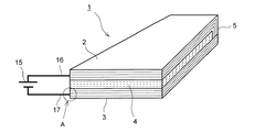
図1に示すように、繊維強化プラスチック発熱体1は、主に、第1層である炭素繊維強化プラスチック層2と、第2層である炭素繊維強化プラスチック層3と、絶縁層4と、接続部5と、直流電源15とを備える。
[First Embodiment]
A fiber-reinforced plastic heating element according to the first embodiment of the present invention will be described with reference to FIG. FIG. 1 is a perspective view showing a fiber-reinforced plastic heating element according to the first embodiment of the present invention.
As shown in FIG. 1, the fiber reinforced
炭素繊維強化プラスチック層(以下、CFRP層と称する)2,3はいずれも、シート状の炭素繊維強化プラスチック(以下、CFRPと称する)が複数積層された構造であってもよい。これらのCFRP層2,3は、平板形状を有しているが、適用する構造体(例えば風力発電装置のブレードや航空機の主翼)の形状に応じて曲率を有していてもよい。 Each of the carbon fiber reinforced plastic layers (hereinafter referred to as CFRP layers) 2 and 3 may have a structure in which a plurality of sheet-like carbon fiber reinforced plastics (hereinafter referred to as CFRP) are laminated. These CFRP layers 2 and 3 have a flat plate shape, but may have a curvature according to the shape of a structure to be applied (for example, a blade of a wind power generator or a main wing of an aircraft).
絶縁層4は、CFRP層2,3の間に配置される。すなわち、CFRP2、絶縁層4、CFRP層3の順に積層配置される。したがって、絶縁層4の両面にCFRP層2,3が位置することとなる。また、絶縁層4は、ガラス繊維強化プラスチック層(以下、GFRP層と称する)であることが好ましい。このように、絶縁層4をガラス繊維強化プラスチック層で形成することによって、CFRP層2,3間の絶縁性を確保しながら、構造体としての強度をより一層向上させることができる。なお、絶縁層4としてGFRP層を用いる場合、GFRP層は、シート状のガラス繊維強化プラスチックが複数積層された構造であってもよい。
The insulating
接続部5は、CFRP層2,3を電気的に接続する。この接続部5は、CFRP層2,3の一側の端部に設けられることが好ましい。なお、図1では一例として、一方のCFRP層2の端部を屈曲させて他方のCFRP層3に接触させ、これらを接触部位で接合することによって電気的な接続を確保している。これにより、CFRP層2、接続部5、CFRP層3からなる電気的経路が形成される。接続部5の他の構成例は後述する。
なお、CFRP層2,3が、シート状の炭素繊維強化プラスチックを複数積層した構造である場合、その積層方向と、CFRP層2−絶縁層4−CFRP層3の積層方向とは、同一の方向であっても異なる方向であってもよい。同様に、絶縁層4としてGFRP層が用いられ且つGFRP層がシート状のガラス繊維強化プラスチックを複数積層した構造である場合、その積層方向と、CFRP層2−GFRP層4−CFRP層3の積層方向とは、同一の方向であっても異なる方向であってもよい。また、CFRP層2,3に含まれる強化繊維の配列方向についても特に限定されないが、長尺の繊維強化プラスチック発熱体1の場合、発熱体の強度および製造し易さの観点から、長手方向に沿って強化繊維が配置されることが好ましい。
The
When the CFRP layers 2 and 3 have a structure in which a plurality of sheet-like carbon fiber reinforced plastics are laminated, the lamination direction and the lamination direction of the CFRP layer 2 -insulating layer 4 -
ここで、繊維強化プラスチック発熱体1の製造方法の例を以下に述べる。
一つの方法として、シート状のCFRPおよびシート状のガラス繊維強化プラスチック(以下、GFRPと称する)をそれぞれ積層配置して樹脂を含浸させ、固化させる真空含浸法によって一体に成型してもよい。この成型方法は、まず、シート状のCFRPとシート状のGFRPとを成形型上に積層配置し、これらをバッグフィルムで覆って密閉する。このとき、バッグフィルムとCFRPおよびGFRPとの間に離型フィルムと樹脂の拡散媒体として用いるメッシュシートとを介装しておく。そして、バッグフィルムの内側を真空吸引し、バッグフィルムの内部に液状樹脂を注入して硬化させる。樹脂が硬化した後、離型フィルムを剥離してバッグフィルムとメッシュシートとを除去することによって、CFRP層およびGFRP層からなる繊維強化プラスチック発熱体1が製造できる。
Here, the example of the manufacturing method of the fiber reinforced plastic
As one method, sheet-like CFRP and sheet-like glass fiber reinforced plastic (hereinafter referred to as GFRP) may be laminated and impregnated with resin, and may be integrally molded by a vacuum impregnation method in which the resin is solidified. In this molding method, first, a sheet-like CFRP and a sheet-like GFRP are stacked on a mold, and these are covered with a bag film and sealed. At this time, a release film and a mesh sheet used as a resin diffusion medium are interposed between the bag film and CFRP and GFRP. And the inside of a bag film is vacuum-sucked and liquid resin is inject | poured into the inside of a bag film, and is hardened. After the resin is cured, the release film is peeled off to remove the bag film and the mesh sheet, whereby the fiber-reinforced
なお、図1に示すように、CFRP2の端部を屈曲させて接続部5を形成する場合、CFRP2の端部を屈曲させた状態で真空吸引して樹脂を硬化させてもよい。また、後述するように、接続部を金属製部材によって形成する場合、真空吸引時の外圧で、CFRPと金属製部材を互いに押しつけながら成型することでこれらを連結することができる。
また、別の方法として、シート状のCFRPおよびシート状のGFRPの間に接着剤を介装しながらそれぞれ積層配置し、接着剤を固化させることによって繊維強化プラスチック発熱体1を製造することができる。
ただし、繊維強化プラスチック発熱体1の製造方法は上記に限定されるものではない。
As shown in FIG. 1, when the end portion of the
As another method, the fiber-reinforced
However, the manufacturing method of the fiber reinforced
直流電源15は、一側の端子16がCFRP層2に接続され、他側の端子17がCFRP層3に接続される。そして、これらの間に電圧を印加することによってCFRP層2、接続部5、CFRP層3からなる電気的経路に直流電流を流す。なお、直流電源の端子16,17は、接続部5とは反対側のCFRP層2の端部に設けられることが好ましい。
The
上記構成を備える繊維強化プラスチック発熱体1によれば、寒冷時に、直流電源15によってCFRP層2,3に電流を流すことで、CFRP2,3が発熱する。これにより、構造体が加熱され、構造体表面への着氷防止および脱氷が可能となる。
According to the fiber-reinforced
以上説明したように、本実施形態によれば、CFRP層2,3を積層体の一部の層として用いるとともに、絶縁層4の両面に設けられて接続部5で電気的に接続される2つの導電層(少なくとも一方はCFRP層2,3)の間に電流を流すことによって、高比強度を有する構造部材でありながら、発熱機能、すなわち着氷防止または脱氷の機能を付与することが可能となる。
As described above, according to the present embodiment, the CFRP layers 2 and 3 are used as a part of the laminated body, and are provided on both surfaces of the insulating
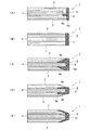
なお、上述の第1実施形態では、接続部5が、一方のCFRP層2の一端部から形成される例について説明したが、他の接続部の構成を採用してもよい。図2は、CFRP層同士の接続部の他の構成例を示す断面図である。図2(A)〜(E)に示す接続部の構造は、CFRP層2,3にそれぞれ接触するようにこれらの層の間に挿入された金属製部材6からなる。ここで、金属製部材6は、導電性金属からなる接続用部材であり、導電性金属としては、例えば、銅、鉄、アルミニウム、またはこれらの合金等が用いられる。
In the above-described first embodiment, the example in which the
具体的に、図2(A)では、接続部5を構成する金属製部材6は、CFRP層2,3および絶縁層4の積層方向に設けられた平板部6aと、平板部6aから略垂直に延出した延出部6bとを含み、断面T字状に形成されている。一方のCFRP層2は、図1と同様に一端部が屈曲されており、その屈曲部と他方のCFRP層3の端部とが平板部6aに接触している。また、一方のCFRP層2の屈曲部の端部と、他方のCFRP層3の端部とが、延出部6bに接触している。これにより、CFRP層2,3が電気的に接続される。このように、金属製部材6によってCFRP層2,3を接続することにより、導電率を向上させることができ、電源15から供給される電流によってCFRP層2,3で効果的に発熱させることができる。
Specifically, in FIG. 2A, the
図2(B)では、接続部5を構成する金属製部材7は、CFRP層2,3および絶縁層4の積層方向に設けられた平板部7aからなる。平板部7aは、CFRP層2,3および絶縁層4の積層方向に配置される。そして、一方のCFRP層2の端部と、他方のCFRP層3の端部とが平板部7aにそれぞれ接触している。これにより、CFRP層2,3が電気的に接続される。このように、平板部7aからなる金属製部材7によってCFRP層2,3を接続することにより、金属製部材7の形状を簡素化することができる。
In FIG. 2B, the metal member 7 constituting the connecting
図2(C)では、接続部5を構成する金属製部材8は、CFRP層2,3との接合界面がそれぞれテーパ状に形成されている。すなわち、金属製部材8は、その端面8aから、CFRP層2,3および絶縁層4の延設方向に離れるほどその肉厚が小さくなるテーパ形状を有する。この金属製部材8のテーパ面8b,8bに対応して、金属製部材8に接触するCFRP層2,3の端部も、それぞれ、外縁側の肉厚が薄くなるようなテーパ状に形成されている。このように、金属製材料8とCFRP層2,3との接合界面をそれぞれテーパ状に形成することによって、接合界面における接合強度を高くすることができる。すなわち、接合界面をテーパ形状に形成することで、異種材料間の接合部において接合界面の接着面積が増加し、弾性率の変化も連続的となって局所的なピーク応力が低減するので、結果として接合強度を高くすることができるものである。
In FIG. 2 (C), the
図2(D)では、接合部5を構成する金属製部材9は、断面が凹形状に形成され、凹部9aに絶縁層4の端部が挿入されている。そして、凹部9aの外面9b,9bに、CFRP層2,3が接触している。さらに、外面9b,9bに接触するCFRP層2,3の端部を、それぞれ、外縁側の肉厚が薄くなるようなテーパ状に形成している。このように、CFRP層2,3の端部をテーパ状に形成することによって、簡素化された構造で以って、金属製材料9とCFRP層2,3との接合界面における接合強度を高くすることができる。
In FIG. 2D, the metal member 9 constituting the
図2(E)では、CFRP層2,3および絶縁層4を、それぞれ、外縁側の肉厚が薄くなるようなテーパ状に形成している。さらに、接続部を構成する金属製部材10を、テーパ状のCFRP層2,3の端部をそれぞれ被覆するように配置している。このように、CFRP層2,3および絶縁層4を、それぞれテーパ状に形成することによって、金属製材料10とCFRP層2,3との接合界面における接合強度を高くするとともに、耐久性を向上させることができ、さらに、簡素化された構造とすることができる。
In FIG. 2 (E), the CFRP layers 2 and 3 and the insulating
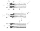
また、CFRP層2,3と、直流電源15の端子16,17との間の接続部は、以下の構成を採用してもよい。図3は、CFRP層と外部回路との接続部の構成例を示す断面図である。つまり、図1で示すA部分の拡大図である。ここで、外部回路とは、直流電源15、端子16,17を含む回路をいう。
図3(A)〜(C)に示す接続部は、CFRP層2,3の端部にそれぞれ設けられた金属製部材によって、CFRP層2,3と外部回路とが接続されるようになっている。このように、金属製部材を介して接続することで、導電率を向上させることができる。
Further, the following configuration may be adopted for the connection between the CFRP layers 2 and 3 and the
3A to 3C, the CFRP layers 2 and 3 and the external circuit are connected to each other by metal members provided at the ends of the CFRP layers 2 and 3, respectively. Yes. Thus, electrical conductivity can be improved by connecting via a metal member.
図3(A)では、一方のCFRP層2に接触する金属製部材21と、他方のCFRP層2に接触する金属製部材22とがそれぞれ電気的に独立して設けられている。各金属製部材21,22は、接続側の端面21a,22aから、CFRP層2,3および絶縁層4の延設方向に離れるほどその肉厚が小さくなるテーパ形状を有する。このテーパ面21b,22bに対応して、CFRP層2,3の端部もテーパ形状となっている。このように、金属製材料21,22とCFRP層2,3との接合界面をそれぞれテーパ状に形成することによって、接合界面における接合強度を高くすることができる。
In FIG. 3A, a
図3(B)では、接合部を構成する金属製部材23,24は、それぞれ平板状に形成されており、これらの金属製部材23,24の一側の面は絶縁層4に接触し、他側の面はCFRP層2,3に接触している。さらに、他側の面に接触するCFRP層2,3の端部を、それぞれ、外縁側の肉厚が薄くなるようなテーパ状に形成している。このように、CFRP層2,3の端部をテーパ状に形成することによって、簡素化された構造で以って、金属製材料23,24とCFRP層2,3との接合界面における接合強度を高くすることができる。
In FIG. 3 (B), the
図3(C)では、接合部を構成する金属製部材25,26は、それぞれ積層方向における断面がテーパ状になるように形成され、且つ対向するテーパ角が略同一となっている。このテーパ状の金属製部材25,26に応じて、CFRP層2,3には凹部が形成され、この凹部内に金属製部材25,26の先端が挿入されている。絶縁層4は、金属製部材25,26の基部(接触側部位)に接触している。これにより、金属製材料25,26とCFRP層2,3との接合界面における接合強度を高くするとともに、耐久性を向上させることができる。
In FIG. 3C, the
なお、本実施形態に係る繊維強化プラスチック発熱体10は、風力発電装置のブレード、航空機の主翼等のように、外気に晒される各種の構造体に適用できる。
ここで、一例として、風力発電装置への適用例を説明する。
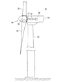
図4は、風力発電装置30の構成例である。図4に示すように、風力発電装置30は、1本以上(この例では3本)のブレード35と、ブレード35が取り付けられるハブ36と、ブレード35及びハブ36を含むロータ34を支持するナセル33と、ナセル33を旋回自在に支持するタワー32とを備える。なお、ロータ34の回転は、メインシャフト38から増速機38を介して発電機39に入力されて、該発電機39において電力が生成されるようになっている。
タワー32は、基礎上に立設される。基礎は、陸上風力発電装置の場合は地上に、洋上風力発電装置の場合は洋上に設けられている。なお、本実施形態に係る風力発電装置30は、陸上風力発電装置及び洋上風力発電装置のいずれにも適用可能である。
The fiber-reinforced
Here, as an example, an application example to a wind turbine generator will be described.
FIG. 4 is a configuration example of the
The
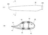
図5(A)に示す風車翼の平面図のように、ブレード35は、ハブ36に連結される翼根部35Aから翼先端部35Bまで延在する長尺な形状を有している。
図5(B)は、図5(A)のA−A矢視断面図である。同図に示すように、ブレード35は、主に、外皮材41と、スパーキャップ(主強度材)42と、シアウェブ(桁材)43とを有する。
スパーキャップ42は、主に、繊維強化プラスチック(FRP)で形成されている。
外皮材41は、その他の部分とともにブレード35の翼形を構成するものである。外皮材41およびその他の部分は、例えば、ガラス繊維プラスチック層やコア材で形成されていてもよい。
シアウェブ43は、外皮材41の内部空間に、翼長方向に延在している。また、シアウェブ43は、背側に設けられたスパーキャップ42と、腹側に設けられたスパーキャップ42とを結合し、これによりブレード35の強度を高める。
As shown in the plan view of the wind turbine blade shown in FIG. 5A, the
FIG. 5B is a cross-sectional view taken along arrow AA in FIG. As shown in the figure, the
The
The
The
このように、ブレード35は、その大部分が繊維強化プラスチックで構成されることが多い。したがって、本実施形態に係る繊維強化プラスチック発熱体10を、ブレード35の少なくとも一部として用いることで、構造体として本来の強度を維持しながら、着氷防止および脱氷の機能を付与することができる。
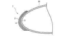
特に、図6に示すように、繊維強化プラスチック発熱体10は、ブレード35の前縁に配置することが好ましい。風力発電装置1のブレード35は、水分を含む風の大部分が主に前縁に衝突する。したがって、ブレード35の前縁は着氷しやすい。そのため、ブレード35の前縁に繊維強化プラスチック発熱体10を配置することによって、着氷防止および脱氷の機能を効果的に発揮することができる。
As described above, the
In particular, as shown in FIG. 6, it is preferable that the fiber-reinforced
[第2実施形態]
次に第2実施形態に係る風力発電装置について説明する。本実施形態の繊維強化プラスチック発熱体1’は、一方の炭素繊維強化プラスチックを金属メッシュに替えたことを除けば、既に説明した第1実施形態の繊維強化プラスチック発熱体10と同様の構成である。したがって、ここでは、第1実施形態と共通する部材には同一の符号を付してその説明を省略し、第1実施形態と異なる部分を中心に説明する。
[Second Embodiment]
Next, a wind turbine generator according to a second embodiment will be described. The fiber-reinforced
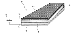
図7は、本発明の第2実施形態に係る繊維強化プラスチック発熱体を示す斜視図である。同図に示すように、繊維強化プラスチック発熱体1’は、繊維強化プラスチック発熱体1は、主に、第1層であるCFRP層2と、第2層である金属メッシュ51と、絶縁層4と、接続部5と、直流電源15とを備える。
FIG. 7 is a perspective view showing a fiber-reinforced plastic heating element according to the second embodiment of the present invention. As shown in the figure, the fiber reinforced
金属メッシュ51は、導電性金属から構成される。導電性金属としては、例えば、銅、鉄、アルミニウム、またはこれらの合金等が用いられる。なお、ここでは金属メッシュ51を例に説明するが、導電性金属から構成される平板状体であればメッシュ状でなくてもよい。
繊維強化プラスチック発熱体1’は、絶縁層4の一方の面にCFRP層2が配置され、他方の面に金属メッシュ51が配置される。さらに、CFRP層2と金属メッシュ51とは、接続部5によって電気的に接続されている。
このように、絶縁層4の一方の面に金属メッシュ51を用いることによって、構造体への落雷時に、落雷電流が金属メッシュ51を通って流れるので、CFRP層2の損傷を回避することができる。
The
In the fiber reinforced
In this way, by using the
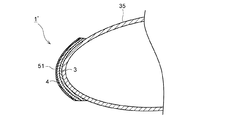
図8は、本発明の第2実施形態に係る繊維強化プラスチック発熱体をブレードに適用した例を示す断面図である。
この繊維強化プラスチック発熱体1’を風力発電装置1(図4参照)のブレード35に適用する場合、落雷時におけるCFRP層2の保護の観点から、CFRP層2がブレード35に面する側に位置し、金属メッシュ51が外側に位置するように繊維強化プラスチック発熱体1’を配置することが好ましい。
FIG. 8 is a cross-sectional view showing an example in which the fiber-reinforced plastic heating element according to the second embodiment of the present invention is applied to a blade.
When this fiber-reinforced
ここで、第2実施形態に係る繊維強化プラスチック発熱体1’における具体的な実験例について示す。図8に示す繊維強化プラスチック発熱体1’の構成を試験体として採用し、長さ10m×幅50cm×厚さ2mmの板状のCFRP層2(CFRP;密度1520kg/m2,比熱1065J/kgK,電気抵抗率9.71×10−6Ωm)を用い、直流電源15から40Aの電流を3時間通電したとき、CFRP層の領域で、表面温度を51.8℃上昇させることができた。この結果から、繊維強化プラスチック発熱体1’を通電状態として作動させる場合、風力発電装置1の運転停止時に3時間以上の通電を行うことによって、ブレード35と接触している界面の氷を溶解させて、脱氷させることができる。
Here, a specific experimental example in the fiber-reinforced
以上、本発明の実施形態について詳細に説明したが、本発明はこれに限定されず、本発明の要旨を逸脱しない範囲において、上述の第1実施形態および第2実施形態を適宜組み合わせてもよいし、図9に示す通り面内方向に各層を配置する等の各種の改良や変形を行ってもよいのはいうまでもない。
ここで、図9を簡単に説明する。図9に示す繊維強化プラスチック発熱体1”は、第1実施形態および第2実施形態のように肉厚方向に各層(CFRP層2,絶縁層4,CFRP層3)を積層するのではなく、発熱体1”の面内方向に各層を配置している。すなわち、肉厚方向には単一の層のみが配置され、発熱体1”の幅方向に、CFRP層2,絶縁層4,CFRP層3が順に配置されている。そして、CFRP層2とCFRP層3の端部が、接続部5で接続された構成となっている。これにより、上述の実施形態と同一の効果が得られる。
As mentioned above, although embodiment of this invention was described in detail, this invention is not limited to this, In the range which does not deviate from the summary of this invention, you may combine the above-mentioned 1st Embodiment and 2nd Embodiment suitably. However, it goes without saying that various improvements and modifications such as disposing each layer in the in-plane direction as shown in FIG. 9 may be performed.
Here, FIG. 9 will be briefly described. The fiber-reinforced
1,1’,1” 繊維強化プラスチック発熱体
2,3 炭素繊維強化プラスチック層(CFRP層)
4 絶縁層
5 接続部
6〜10 金属製部材
6a 平板部
6b 延出部
8a 端面
8b テーパ面
9a 凹部
9b 外面
15 直流電源
21〜26 金属製部材
21a,22a 端面
21b,22b テーパ面
30 風力発電装置
32 タワー
33 ナセル
34 ロータ
35 ブレード
36 ハブ
39 発電機
41 外皮材
42 スパーキャップ
43 シアウェブ
1,1 ', 1 "fiber reinforced
DESCRIPTION OF
Claims (8)
炭素繊維強化プラスチック層からなる第1層と、
炭素繊維強化プラスチック層および導電性金属層のいずれか一方からなる第2層と、
前記第1層と前記第2層との間に配置される絶縁層と、
前記第1層および前記第2層を電気的に接続する接続部と、
前記第1層および前記第2層に電気的に接続され、前記第1層、前記接続部および前記第2層からなる電気的経路に電流を流す電源とを備えることを特徴とする繊維強化プラスチック発熱体。 A fiber reinforced plastic heating element formed by laminating a plurality of layers,
A first layer comprising a carbon fiber reinforced plastic layer;
A second layer comprising either one of a carbon fiber reinforced plastic layer and a conductive metal layer;
An insulating layer disposed between the first layer and the second layer;
A connecting portion for electrically connecting the first layer and the second layer;
A fiber reinforced plastic comprising: a power source that is electrically connected to the first layer and the second layer, and that causes a current to flow through an electrical path including the first layer, the connection portion, and the second layer. Heating element.
A wind power generator comprising a blade formed at least in part by the fiber-reinforced plastic heating element according to claim 1.
Priority Applications (2)
| Application Number | Priority Date | Filing Date | Title |
|---|---|---|---|
| JP2012042922A JP5675673B2 (en) | 2012-02-29 | 2012-02-29 | Fiber reinforced plastic heating element and wind power generator equipped with the heating element |
| PCT/JP2012/071962 WO2013128682A1 (en) | 2012-02-29 | 2012-08-30 | Fiber-reinforced plastic heating element and wind power generating device comprising said heating element |
Applications Claiming Priority (1)
| Application Number | Priority Date | Filing Date | Title |
|---|---|---|---|
| JP2012042922A JP5675673B2 (en) | 2012-02-29 | 2012-02-29 | Fiber reinforced plastic heating element and wind power generator equipped with the heating element |
Publications (2)
| Publication Number | Publication Date |
|---|---|
| JP2013178999A JP2013178999A (en) | 2013-09-09 |
| JP5675673B2 true JP5675673B2 (en) | 2015-02-25 |
Family
ID=49081914
Family Applications (1)
| Application Number | Title | Priority Date | Filing Date |
|---|---|---|---|
| JP2012042922A Active JP5675673B2 (en) | 2012-02-29 | 2012-02-29 | Fiber reinforced plastic heating element and wind power generator equipped with the heating element |
Country Status (2)
| Country | Link |
|---|---|
| JP (1) | JP5675673B2 (en) |
| WO (1) | WO2013128682A1 (en) |
Cited By (1)
| Publication number | Priority date | Publication date | Assignee | Title |
|---|---|---|---|---|
| US11754038B2 (en) | 2021-05-04 | 2023-09-12 | Doosan Enerbility Co., Ltd. | Wind turbine blade and wind turbine including the same |
Families Citing this family (12)
| Publication number | Priority date | Publication date | Assignee | Title |
|---|---|---|---|---|
| US8973871B2 (en) * | 2013-01-26 | 2015-03-10 | The Boeing Company | Box structures for carrying loads and methods of making the same |
| JP5878963B2 (en) * | 2013-11-18 | 2016-03-08 | 富士重工業株式会社 | Specimen and current measurement method |
| GB2526845A (en) * | 2014-06-05 | 2015-12-09 | Vestas Wind Sys As | Improvements relating to lightning protection systems for wind turbine blades |
| US20170238367A1 (en) * | 2016-02-15 | 2017-08-17 | General Electric Company | Integrated Conductive Foam Core for Composite Processing |
| KR102579111B1 (en) * | 2016-06-02 | 2023-09-15 | 이승수 | Heating unit manufacturing method and beauty equipment having the same |
| DK3577340T3 (en) * | 2017-02-06 | 2022-08-29 | Kjell Lindskog | PROCEDURE AND SETUP IN CONNECTION WITH HEATING OF WIND TURBINE BLADES |
| JP7133162B2 (en) * | 2017-12-11 | 2022-09-08 | 株式会社高速道路総合技術研究所 | METHOD FOR DETECTING DAMAGE AND DEFORMATION IN STRUCTURES HAVING CFRP STRAINS FOR PRESTRAINING PRESTRESS AND CFRP STRAINS |
| JP7223386B2 (en) | 2017-12-15 | 2023-02-16 | 国立研究開発法人宇宙航空研究開発機構 | fan blade and engine |
| JP6484378B1 (en) * | 2018-09-21 | 2019-03-13 | 太平洋工業株式会社 | Resin molded product and method for producing resin molded product |
| EP3869035B2 (en) * | 2020-02-21 | 2026-02-11 | Siemens Gamesa Renewable Energy Innovation & Technology, S.L. | Blade for a rotor of a wind turbine and manufacturing method thereof |
| CN114269549A (en) * | 2020-05-25 | 2022-04-01 | Lm风力发电公司 | Method of manufacturing spar caps for wind turbine blade components |
| EP4019766A1 (en) * | 2020-12-23 | 2022-06-29 | Polytech A/S | A conductive connection |
Family Cites Families (7)
| Publication number | Priority date | Publication date | Assignee | Title |
|---|---|---|---|---|
| JPS4913957Y1 (en) * | 1969-11-10 | 1974-04-06 | ||
| JPS6054181B2 (en) * | 1978-01-28 | 1985-11-29 | 日本カ−ボン株式会社 | Manufacturing method of fiber reinforced plastic |
| JPH0524151Y2 (en) * | 1985-05-30 | 1993-06-18 | ||
| JP3086725B2 (en) * | 1991-09-03 | 2000-09-11 | 株式会社東芝 | Composite members |
| JPH1187022A (en) * | 1997-09-10 | 1999-03-30 | Takezawa Yoshiyuki | Surface heater |
| JPH11149976A (en) * | 1997-11-14 | 1999-06-02 | Takezawa Yoshiyuki | Flat heating sheet and flat heating device |
| JP3314867B2 (en) * | 1998-10-22 | 2002-08-19 | 新日本石油株式会社 | Heating laminate and electric heating board for floor heating |
-
2012
- 2012-02-29 JP JP2012042922A patent/JP5675673B2/en active Active
- 2012-08-30 WO PCT/JP2012/071962 patent/WO2013128682A1/en not_active Ceased
Cited By (1)
| Publication number | Priority date | Publication date | Assignee | Title |
|---|---|---|---|---|
| US11754038B2 (en) | 2021-05-04 | 2023-09-12 | Doosan Enerbility Co., Ltd. | Wind turbine blade and wind turbine including the same |
Also Published As
| Publication number | Publication date |
|---|---|
| WO2013128682A1 (en) | 2013-09-06 |
| JP2013178999A (en) | 2013-09-09 |
Similar Documents
| Publication | Publication Date | Title |
|---|---|---|
| JP5675673B2 (en) | Fiber reinforced plastic heating element and wind power generator equipped with the heating element | |
| US9482208B2 (en) | Wind turbine rotor blade having an electrical heating arrangement and method of making the same | |
| US10632573B2 (en) | Wind turbine blade and related method of manufacture | |
| JP5546624B2 (en) | Windmill wing | |
| CN205805824U (en) | The rotor blade of wind turbine and wind turbine | |
| CN103161689B (en) | Anti-icing and deicing system for large wind power generation built-up blade | |
| CN101876293B (en) | Wind turbine blade with prefabricated leading edge segments | |
| US11746744B2 (en) | Equipotential bonding of wind turbine rotor blade | |
| WO2017033249A1 (en) | Wind power generation device | |
| EP4248086A1 (en) | A spar cap assembly for a wind turbine blade with a lightning protection system | |
| US20200361612A1 (en) | Resistive heated aircraft component and method for manufacturing said aircraft component | |
| JP2013194645A (en) | Blade for wind power generation apparatus | |
| JP5714714B2 (en) | Rotor blade with heating device for wind power generator | |
| US12429031B1 (en) | Equipotential bonding of wind turbine rotor blade | |
| CN106321372A (en) | Composite carbon fiber heating element for wind-driven generator blade ice preventing or ice melting | |
| CN110815860B (en) | Anti-icing blade, preparation method thereof and wind generating set | |
| US12270372B2 (en) | Modular wind turbine blade with lightning protection system | |
| EP4305300B1 (en) | Wind turbine rotor blade spar cap with equipotential bonding | |
| CN120303481A (en) | Wind turbine blades with electric heating system | |
| JP2024523701A (en) | Wind turbine blade with electric heating system | |
| CN114635833B (en) | Anti-icing wind turbine blade and wind turbine generator | |
| WO2025008034A1 (en) | Wind turbine blade shell with heating element |
Legal Events
| Date | Code | Title | Description |
|---|---|---|---|
| A621 | Written request for application examination |
Free format text: JAPANESE INTERMEDIATE CODE: A621 Effective date: 20131129 |
|
| TRDD | Decision of grant or rejection written | ||
| A01 | Written decision to grant a patent or to grant a registration (utility model) |
Free format text: JAPANESE INTERMEDIATE CODE: A01 Effective date: 20141128 |
|
| A61 | First payment of annual fees (during grant procedure) |
Free format text: JAPANESE INTERMEDIATE CODE: A61 Effective date: 20141224 |
|
| R151 | Written notification of patent or utility model registration |
Ref document number: 5675673 Country of ref document: JP Free format text: JAPANESE INTERMEDIATE CODE: R151 |