JP5672527B2 - Image processing apparatus and image processing method - Google Patents
Image processing apparatus and image processing method Download PDFInfo
- Publication number
- JP5672527B2 JP5672527B2 JP2010196231A JP2010196231A JP5672527B2 JP 5672527 B2 JP5672527 B2 JP 5672527B2 JP 2010196231 A JP2010196231 A JP 2010196231A JP 2010196231 A JP2010196231 A JP 2010196231A JP 5672527 B2 JP5672527 B2 JP 5672527B2
- Authority
- JP
- Japan
- Prior art keywords
- noise
- image
- processing
- restoration
- degree
- Prior art date
- Legal status (The legal status is an assumption and is not a legal conclusion. Google has not performed a legal analysis and makes no representation as to the accuracy of the status listed.)
- Active
Links
- 238000003672 processing method Methods 0.000 title claims description 12
- 238000000034 method Methods 0.000 claims description 57
- 230000008859 change Effects 0.000 claims description 52
- 230000008569 process Effects 0.000 claims description 46
- 230000009467 reduction Effects 0.000 claims description 32
- 230000015556 catabolic process Effects 0.000 claims description 30
- 238000006731 degradation reaction Methods 0.000 claims description 30
- 230000035945 sensitivity Effects 0.000 claims description 13
- 238000006243 chemical reaction Methods 0.000 claims description 8
- 230000006870 function Effects 0.000 description 48
- 238000010586 diagram Methods 0.000 description 15
- 238000004364 calculation method Methods 0.000 description 12
- 230000006866 deterioration Effects 0.000 description 5
- 238000011946 reduction process Methods 0.000 description 5
- 238000004590 computer program Methods 0.000 description 4
- 238000005516 engineering process Methods 0.000 description 4
- 230000010354 integration Effects 0.000 description 4
- 230000007423 decrease Effects 0.000 description 3
- 230000003595 spectral effect Effects 0.000 description 3
- 238000004422 calculation algorithm Methods 0.000 description 2
- 230000002708 enhancing effect Effects 0.000 description 2
- 238000003384 imaging method Methods 0.000 description 2
- 230000002238 attenuated effect Effects 0.000 description 1
- 230000002146 bilateral effect Effects 0.000 description 1
- 230000005540 biological transmission Effects 0.000 description 1
- 238000004891 communication Methods 0.000 description 1
- 238000001514 detection method Methods 0.000 description 1
- 230000000694 effects Effects 0.000 description 1
- 238000004519 manufacturing process Methods 0.000 description 1
- 230000003287 optical effect Effects 0.000 description 1
- 239000004065 semiconductor Substances 0.000 description 1
- 230000009466 transformation Effects 0.000 description 1
Images


Classifications
-
- H—ELECTRICITY
- H04—ELECTRIC COMMUNICATION TECHNIQUE
- H04N—PICTORIAL COMMUNICATION, e.g. TELEVISION
- H04N1/00—Scanning, transmission or reproduction of documents or the like, e.g. facsimile transmission; Details thereof
- H04N1/40—Picture signal circuits
- H04N1/409—Edge or detail enhancement; Noise or error suppression
-
- G—PHYSICS
- G06—COMPUTING; CALCULATING OR COUNTING
- G06T—IMAGE DATA PROCESSING OR GENERATION, IN GENERAL
- G06T5/00—Image enhancement or restoration
- G06T5/10—Image enhancement or restoration using non-spatial domain filtering
-
- G—PHYSICS
- G06—COMPUTING; CALCULATING OR COUNTING
- G06T—IMAGE DATA PROCESSING OR GENERATION, IN GENERAL
- G06T5/00—Image enhancement or restoration
- G06T5/70—Denoising; Smoothing
-
- G—PHYSICS
- G06—COMPUTING; CALCULATING OR COUNTING
- G06T—IMAGE DATA PROCESSING OR GENERATION, IN GENERAL
- G06T5/00—Image enhancement or restoration
- G06T5/73—Deblurring; Sharpening
-
- H—ELECTRICITY
- H04—ELECTRIC COMMUNICATION TECHNIQUE
- H04N—PICTORIAL COMMUNICATION, e.g. TELEVISION
- H04N5/00—Details of television systems
- H04N5/14—Picture signal circuitry for video frequency region
- H04N5/21—Circuitry for suppressing or minimising disturbance, e.g. moiré or halo
-
- G—PHYSICS
- G06—COMPUTING; CALCULATING OR COUNTING
- G06T—IMAGE DATA PROCESSING OR GENERATION, IN GENERAL
- G06T2207/00—Indexing scheme for image analysis or image enhancement
- G06T2207/20—Special algorithmic details
- G06T2207/20048—Transform domain processing
- G06T2207/20056—Discrete and fast Fourier transform, [DFT, FFT]
Landscapes
- Engineering & Computer Science (AREA)
- Physics & Mathematics (AREA)
- General Physics & Mathematics (AREA)
- Theoretical Computer Science (AREA)
- Multimedia (AREA)
- Signal Processing (AREA)
- Image Processing (AREA)
- Picture Signal Circuits (AREA)
- Facsimile Image Signal Circuits (AREA)
Description
本発明は、入力画像に生じたぼやけ(blur)を低減するための画像処理装置及び画像処理方法に関するものである。 The present invention relates to an image processing apparatus and an image processing method for reducing blur generated in an input image.
撮影時にフォーカスが合っていないこと(焦点外れ:out−of−focus)、あるいは手振れ(camera shake)などにより入力画像にぼやけが生じる。そこで、ぼやけが生じた入力画像に対して画像復元処理を行うことにより、高精細な出力画像を得ることができる。しかし、画像復元処理では、入力画像の高周波数成分が強調されるため、入力画像に含まれるノイズも増幅される。このため、入力画像にノイズが含まれている場合には、画像復元処理により良好な出力画像を得ることが難しい。 The input image is blurred due to out-of-focus (out-of-focus) or camera shake. Therefore, a high-definition output image can be obtained by performing image restoration processing on the input image in which the blur has occurred. However, in the image restoration process, since the high frequency component of the input image is emphasized, noise included in the input image is also amplified. For this reason, when noise is included in the input image, it is difficult to obtain a good output image by image restoration processing.
そこで、従来、画像復元処理によってノイズが強調されないように、ノイズ情報を利用して復元関数を設計する方法が提案されている(例えば、特許文献1参照)。一般的に、画像復元処理において、以下に示す式(1)のように、劣化関数H(u,v)の逆関数が復元関数M(u,v)として利用されている。 Therefore, conventionally, a method has been proposed in which a restoration function is designed using noise information so that noise is not emphasized by image restoration processing (see, for example, Patent Document 1). In general, in an image restoration process, an inverse function of a degradation function H (u, v) is used as a restoration function M (u, v) as shown in the following equation (1).

ぼやけなどで劣化した画像は、高周波数成分が少ない。つまり、高周波数成分を強調することによって、ぼやけを低減することができる。しかし、このように高周波成分が強調されることにより、ノイズも強調される。 An image deteriorated due to blurring or the like has few high frequency components. That is, blurring can be reduced by enhancing high frequency components. However, noise is also enhanced by enhancing the high-frequency component in this way.
特許文献1に記載の方法では、ノイズのスペクトル密度Sn(u,v)、及び近似理想画像スペクトル密度Sf(u,v)を利用して、以下に示す式(2)のように復元関数M(u,v)が設計されている。 In the method described in Patent Document 1, using the noise spectral density Sn (u, v) and the approximate ideal image spectral density Sf (u, v), the restoration function M is expressed as shown in the following equation (2). (U, v) is designed.
式(2)では、ノイズの密度関数Sn(u,v)と近似理想画像スペクトル密度Sf(u,v)との比からおおよそノイズの量が推定されることを利用して、復元関数が設計されている。つまり、式(2)に示す復元関数では、推定されるノイズの量に基づいて、画像復元処理による復元度合いが調整される。具体的には、ノイズが少ない場合(Sn(u,v)/Sf(u,v)が非常に小さい場合)、式(2)に示す復元関数は、式(1)に示す一般的な復元関数(劣化関数の逆関数)と略同一となり、画像を十分に復元することができる。一方、ノイズが多い場合(Sn(u,v)/Sf(u,v)が大きい場合)、式(2)に示す復元関数では、式(1)に示す一般的な復元関数よりも復元度合いが小さくなり、画像復元処理によってノイズが強調されることが抑制される。 In Expression (2), the restoration function is designed by utilizing the fact that the amount of noise is estimated from the ratio between the noise density function Sn (u, v) and the approximate ideal image spectral density Sf (u, v). Has been. That is, in the restoration function shown in Expression (2), the degree of restoration by the image restoration process is adjusted based on the estimated amount of noise. Specifically, when there is little noise (when Sn (u, v) / Sf (u, v) is very small), the restoration function shown in Equation (2) is the general restoration shown in Equation (1). This is substantially the same as the function (inverse function of the degradation function), and the image can be sufficiently restored. On the other hand, when there is a lot of noise (when Sn (u, v) / Sf (u, v) is large), the degree of restoration is higher in the restoration function shown in Expression (2) than in the general restoration function shown in Expression (1). , And noise is suppressed from being emphasized by the image restoration process.
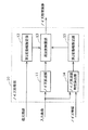
また、画像復元処理の前後に、ノイズを低減する方法が提案されている(例えば、特許文献2参照)。図10は、特許文献2に記載された従来の画像復元処理を示す図である。
In addition, a method for reducing noise before and after the image restoration processing has been proposed (see, for example, Patent Document 2). FIG. 10 is a diagram showing a conventional image restoration process described in
図10に示す従来の画像復元処理において、まず、露出情報検出40において検出された露出情報に基づいて、入力画像のノイズを低減する第1ノイズ低減フィルタ処理30が行われる。次に、ノイズが低減された画像に対して復元処理50が行われる。このように、復元処理50の前にノイズを低減する第1ノイズ低減フィルタ処理30が行われることによって、復元処理50によってノイズが強調されることが抑えられる。また、復元処理50の後に、第2ノイズ低減フィルタ処理60が行われることにより、さらにノイズが低減される。
In the conventional image restoration process shown in FIG. 10, first, a first noise
しかしながら、特許文献1に記載の方法では、ノイズが多い場合、画像復元処理における復元度合いが弱くなるため、画像が十分に復元されない。つまり、特許文献1に記載の方法では、ノイズが多い場合、ボケあるいはブレなどが復元結果画像に残るという課題がある。 However, in the method described in Patent Literature 1, when there is a lot of noise, the degree of restoration in the image restoration process is weakened, and thus the image is not restored sufficiently. That is, the method described in Patent Document 1 has a problem that, when there is a lot of noise, blurring or blurring remains in the restoration result image.
また、特許文献2に記載の方法では、第1ノイズ低減フィルタ処理によってノイズではない真の画像信号まで加工される場合がある。このような場合、第1ノイズ低減フィルタ処理によって画像の劣化が起こり、さらに、復元処理によってその画像の劣化が強調されるという課題がある。
In the method described in
そこで、本発明は、上記従来の課題を解決するものであって、入力画像に生じたぼやけを低減する際に、入力画像に含まれるノイズを低減しつつ、ノイズ処理によって発生する画像の劣化が画像復元処理によって強調されることを抑制することができる画像処理装置及び画像処理方法を提供することを目的とする。 Therefore, the present invention solves the above-described conventional problems, and when reducing blurring generated in an input image, image degradation caused by noise processing is reduced while reducing noise included in the input image. An object of the present invention is to provide an image processing apparatus and an image processing method capable of suppressing emphasis by image restoration processing.
上記従来の課題を解決するために、本発明の一態様に係る画像処理装置は、入力画像に生じたぼやけを低減するための画像処理装置であって、ノイズを低減するノイズ処理を前記入力画像に対して行うことによりノイズ処理画像を生成するノイズ処理部と、ぼやけを低減するための復元関数を用いた画像復元処理を前記ノイズ処理画像に対して行う復元処理部とを備え、前記ノイズ処理部は、前記画像復元処理に用いられる前記復元関数が示す復元度合いが大きいほど前記入力画像に対する前記ノイズ処理画像の変化度合いが制限されるように、前記ノイズ処理を行う。 In order to solve the above conventional problems, an image processing apparatus according to an aspect of the present invention is an image processing apparatus for reducing blurring generated in an input image, and performs noise processing for reducing noise on the input image. A noise processing unit that generates a noise processed image by performing the processing on the noise processing image, and a restoration processing unit that performs an image restoration process using a restoration function for reducing blur on the noise processed image, the noise processing The unit performs the noise processing so that the degree of change of the noise processed image with respect to the input image is limited as the degree of restoration indicated by the restoration function used for the image restoration processing is larger .
この構成によれば、画像復元処理を行う前にノイズ処理を行うので、入力画像に含まれるノイズを低減することができる。さらに、画像復元処理の特性に基づいてノイズ処理を行うので、ノイズ処理によって発生する画像の劣化が画像復元処理によって強調されることを抑制することもできる。 According to this configuration, since noise processing is performed before image restoration processing, noise included in the input image can be reduced. Furthermore, since the noise processing is performed based on the characteristics of the image restoration processing, it is possible to suppress image degradation caused by the noise processing from being emphasized by the image restoration processing.
また、前記ノイズ処理部は、前記復元度合いが大きいほど、前記入力画像に対する前記ノイズ処理画像の周波数領域における変化度合いが制限されるように、前記ノイズ処理を行うことが好ましい。 Also, the noise processing unit, the more the restoration degree is large, so that the degree of change in the frequency region of the noise processed image for the input image is restricted, it is preferable to perform the noise processing.
この構成によれば、入力画像に対するノイズ処理画像の周波数領域における変化度合いを画像復元処理の特性に応じて制限することができるので、ノイズ処理によって発生する画像の劣化が画像復元処理によって強調されることを効率的に抑制することができる。 According to this configuration, since the degree of change in the frequency domain of the noise processed image with respect to the input image can be limited according to the characteristics of the image restoration processing, image degradation caused by the noise processing is emphasized by the image restoration processing. This can be efficiently suppressed.
また、前記復元関数は、周波数領域における周波数ごとの復元度合いを示すことが好ましい。 Further, the restoration function is preferably a score indicates restoration degree for each frequency in the frequency domain.
この構成によれば、復元関数が示す復元度合いに応じて、変化度合いを制限することができるので、ノイズ処理によって発生する画像の劣化が画像復元処理によって強調されることを効率的に抑制することができる。 According to this configuration, since the degree of change can be limited according to the degree of restoration indicated by the restoration function, it is possible to efficiently suppress deterioration of the image caused by noise processing from being emphasized by the image restoration processing. Can do.
また、前記ノイズ処理部は、前記復元度合いが大きい周波数ほど当該周波数における前記変化度合いが制限されるように、前記ノイズ処理を行うことが好ましい。 In addition, it is preferable that the noise processing unit performs the noise processing such that the degree of change in the frequency is limited as the restoration degree increases.
この構成によれば、復元度合いが大きい周波数ほど当該周波数における変化度合いを制限することができる。したがって、画像の劣化が強調されやすい周波数ほど画像の劣化が発生しないようにすることができ、ノイズ処理によって発生する画像の劣化が画像復元処理によって強調されることを効率的に抑制することができる。 According to this configuration, the degree of change in the frequency can be limited as the restoration degree increases. Therefore, it is possible to prevent image degradation from occurring at frequencies where image degradation is more easily emphasized, and to effectively suppress image degradation caused by noise processing from being enhanced by image restoration processing. .
また、前記ノイズ処理部は、前記入力画像に対して空間領域でノイズ低減処理を行うことにより、ノイズ低減画像を生成するノイズ低減部と、前記復元度合いが大きい周波数ほど当該周波数における前記変化度合いを制限するための第1変動幅が小さくなるように、第1変動幅を周波数ごとに設定する第1変動幅設定部と、前記変化度合いの大きさを示す変化度が前記第1変動幅を超えないように前記ノイズ低減画像を加工することにより、前記ノイズ処理画像を生成する周波数制限部とを有することが好ましい。 In addition, the noise processing unit performs noise reduction processing on the input image in a spatial domain, thereby generating a noise reduction image, and the degree of change in the frequency as the restoration degree increases. A first fluctuation range setting unit that sets the first fluctuation range for each frequency so that the first fluctuation range for limiting becomes smaller, and the degree of change indicating the magnitude of the degree of change exceeds the first fluctuation range. It is preferable to have a frequency limiting unit that generates the noise-processed image by processing the noise-reduced image so as not to exist.
この構成によれば、変化度が第1変動幅を超えないようにノイズ低減画像を加工することにより、復元度合いが大きい周波数ほど当該周波数における変化度合いが制限されるノイズ処理画像を容易に生成することができる。 According to this configuration, by processing the noise-reduced image so that the degree of change does not exceed the first fluctuation range, a noise-processed image in which the degree of change in the frequency is limited as the restoration degree increases is easily generated. be able to.
また、前記周波数制限部は、前記入力画像及び前記ノイズ低減画像を空間領域から周波数領域に変換する領域変換部と、周波数領域に変換された入力画像の振幅と周波数領域に変換されたノイズ低減画像の振幅との差分値の絶対値を前記変化度として周波数ごとに算出する比較部と、算出された前記変化度が前記第1変動幅を超えるか否かを周波数ごとに判定し、前記変化度が前記第1変動幅を超えると判定された場合に、当該周波数における前記変化度が前記第1変動幅と一致するように前記ノイズ低減画像の振幅を加工する加工部とを有することが好ましい。 The frequency limiting unit includes a region converting unit that converts the input image and the noise-reduced image from a spatial region to a frequency region, an amplitude of the input image converted into the frequency region, and a noise-reduced image converted into the frequency region. A comparison unit that calculates an absolute value of a difference value with respect to an amplitude for each frequency as the degree of change, and determines for each frequency whether the calculated degree of change exceeds the first fluctuation range, and the degree of change It is preferable to include a processing unit that processes the amplitude of the noise-reduced image so that the degree of change in the frequency coincides with the first fluctuation range when it is determined that exceeds the first fluctuation range.
この構成によれば、変化度が第1変動幅を超える場合には、変化度が第1変動幅と一致するようにノイズ低減画像を加工することができる。したがって、できる限りノイズを低減しつつ、ノイズ処理によって発生する画像の劣化が画像復元処理によって強調されることを抑制することができる。 According to this configuration, when the degree of change exceeds the first fluctuation range, the noise-reduced image can be processed so that the degree of change matches the first fluctuation range. Therefore, it is possible to suppress image degradation caused by noise processing from being emphasized by image restoration processing while reducing noise as much as possible.
また、さらに、前記入力画像のノイズ情報に基づいて、周波数に関わらず均一の第2変動幅を設定する第2変動幅設定部を備え、前記周波数制限部は、前記変化度が前記第1変動幅及び前記第2変動幅を超えないように前記ノイズ低減画像を加工することにより、前記ノイズ処理画像を生成することが好ましい。 Further, a second variation range setting unit that sets a uniform second variation range regardless of the frequency based on noise information of the input image is provided, and the frequency limiting unit has the degree of change of the first variation. The noise-processed image is preferably generated by processing the noise-reduced image so as not to exceed a width and the second fluctuation range.
この構成によれば、さらに、ノイズの振幅が周波数に関わらず均一であることを利用して、ノイズ処理によって画像が劣化することを抑制することができる。 According to this configuration, it is possible to further suppress degradation of an image due to noise processing by utilizing the fact that the noise amplitude is uniform regardless of the frequency.
また、前記ノイズ情報は、カメラのセンサー特性、前記入力画像が撮影された時のISO感度、及び前記入力画像の輝度を利用して算出されることが好ましい。 The noise information is preferably calculated using sensor characteristics of a camera, ISO sensitivity when the input image is taken, and luminance of the input image.
この構成によれば、カメラのセンサー特性、入力画像が撮影された時のISO感度、及び入力画像の輝度を利用して算出されたノイズ情報に基づいて第2変動幅を高精度に設定することが可能となる。 According to this configuration, the second fluctuation range is set with high accuracy based on the noise characteristics calculated using the sensor characteristics of the camera, the ISO sensitivity when the input image is captured, and the luminance of the input image. Is possible.
また、前記ノイズ処理部は、前記画像復元処理の特性と前記入力画像のノイズ情報とに基づいて、前記ノイズ処理を行うことが好ましい。 Moreover, it is preferable that the noise processing unit performs the noise processing based on characteristics of the image restoration processing and noise information of the input image.
この構成によれば、さらに、ノイズ情報に基づいてノイズ処理を行うことができるので、ノイズ処理によって画像が劣化することを抑制することができる。 According to this configuration, since it is possible to perform noise processing based on noise information, it is possible to suppress deterioration of an image due to noise processing.
また、前記ノイズ情報は、カメラのセンサー特性、前記入力画像が撮影された時のISO感度、及び前記入力画像の輝度を利用して算出されることが好ましい。 The noise information is preferably calculated using sensor characteristics of a camera, ISO sensitivity when the input image is taken, and luminance of the input image.
この構成によれば、カメラのセンサー特性、入力画像が撮影された時のISO感度、及び入力画像の輝度を利用して算出されたノイズ情報に基づいてノイズ処理を行うことができるので、ノイズ処理によって画像が劣化することをさらに抑制することができる。 According to this configuration, noise processing can be performed based on noise information calculated using the sensor characteristics of the camera, the ISO sensitivity when the input image is captured, and the luminance of the input image. Can further suppress deterioration of the image.
また、前記復元関数は、前記入力画像の画像劣化関数を利用して導出されることが好ましい。 The restoration function is preferably derived using an image degradation function of the input image.
この構成によれば、入力画像の画像劣化関数を利用して導出される画像復元処理の特性に基づいて、ノイズ処理を行うことができる。 According to this configuration, it is possible to perform noise processing based on the characteristics of the image restoration process derived using the image degradation function of the input image.
また、上記画像処理装置は集積回路として構成されてもよい。 The image processing apparatus may be configured as an integrated circuit.
また、本発明は、このような画像処理装置として実現することができるだけでなく、このような画像処理装置が備える特徴的な構成部の動作をステップとする画像処理方法として実現することができる。また、本発明は、画像処理方法に含まれる各ステップをコンピュータに実行させるプログラムとして実現することもできる。そして、そのようなプログラムは、CD−ROM(Compact Disc Read Only Memory)等のコンピュータ読み取り可能な非一時的な記録媒体あるいはインターネット等の伝送媒体を介して配信することができるのは言うまでもない。 In addition, the present invention can be realized not only as such an image processing apparatus but also as an image processing method in which the operations of characteristic components included in such an image processing apparatus are used as steps. The present invention can also be realized as a program that causes a computer to execute each step included in the image processing method. Such a program can be distributed via a computer-readable non-transitory recording medium such as a CD-ROM (Compact Disc Read Only Memory) or a transmission medium such as the Internet.
本発明によれば、画像復元処理を行う前にノイズ処理を行うので、入力画像に含まれるノイズを低減することができる。さらに、画像復元処理の特性に基づいてノイズ処理を行うので、ノイズ処理によって発生する画像の劣化が画像復元処理によって強調されることを抑制することもできる。 According to the present invention, since noise processing is performed before image restoration processing, noise included in the input image can be reduced. Furthermore, since the noise processing is performed based on the characteristics of the image restoration processing, it is possible to suppress image degradation caused by the noise processing from being emphasized by the image restoration processing.
以下、本発明の実施の形態について、図面を参照しながら説明する。 Hereinafter, embodiments of the present invention will be described with reference to the drawings.
(実施の形態1)
図1は、本発明の実施の形態1に係る画像処理装置100の機能構成を示すブロック図である。
(Embodiment 1)
FIG. 1 is a block diagram showing a functional configuration of an
画像処理装置100は、入力画像に生じたぼやけを低減する。図1に示すように、画像処理装置100は、ノイズ処理部10と、復元処理部20とを備える。
The
ノイズ処理部10は、入力された入力画像のノイズ低減を行う。つまり、ノイズ処理部10は、ノイズを低減するノイズ処理を入力画像に対して行うことによりノイズ処理画像を生成する。このとき、ノイズ処理部10は、復元処理部20が行う画像復元処理の特性に基づいてノイズ処理を行う。つまり、ノイズ処理部10は、画像復元処理の特性に基づいて、ノイズが低減される度合いを調整しながらノイズ処理を行う。
The
具体的には、ノイズ処理部10は、ノイズ処理画像の変化度合いが画像復元処理の特性に応じて制限されるようにノイズ処理を行う。ここで、ノイズ処理画像の変化度合いとは、入力画像に対するノイズ処理画像の周波数領域における変化の度合いを示す。
Specifically, the
より具体的には、ノイズ処理部10は、復元関数が示す復元度合いに応じて変化度合いが制限されるようにノイズ処理を行う。本実施の形態では、ノイズ処理部10は、復元度合いが大きい周波数ほど当該周波数における変化度合いが制限されるようにノイズ処理を行う。
More specifically, the
ここで、復元度合いとは、画像復元処理によって処理対象画像の周波数成分が変更される度合いを示す。つまり、復元度合いが大きいほど、画像復元処理によって周波数成分が大きく変更される。 Here, the restoration degree indicates the degree to which the frequency component of the processing target image is changed by the image restoration process. That is, the greater the degree of restoration, the larger the frequency component is changed by the image restoration process.
復元処理部20は、ぼやけを低減する画像復元処理をノイズ処理画像に対して行うことにより、出力画像を生成する。具体的には、復元処理部20は、周波数領域における周波数ごとの復元度合いを示す復元関数を用いて画像復元処理を行う。
The
なお、画像復元処理のアルゴリズムは、ぼやけが低減されればどのようなアルゴリズムであってもよい。例えば最も単純には、画像復元処理は、式(1)に示す復元関数を周波数領域においてノイズ処理画像に乗算する処理である。また例えば、画像復元処理は、公知のリチャードソンルーシ(LR)法あるいはウィーナフィルタ法などを用いた処理であってもよい。 Note that the algorithm of the image restoration process may be any algorithm as long as blurring is reduced. For example, in the simplest case, the image restoration process is a process of multiplying the noise-processed image in the frequency domain by the restoration function shown in Expression (1). Further, for example, the image restoration process may be a process using a known Richardson Rus (LR) method or a Wiener filter method.
次に、ノイズ処理部10の機能構成の詳細について説明する。
Next, details of the functional configuration of the
図2は、本発明の実施の形態1に係るノイズ処理部10の機能構成を示すブロック図である。
FIG. 2 is a block diagram showing a functional configuration of the
図2に示すように、ノイズ処理部10は、ノイズ低減部11と、第1変動幅設定部12と、周波数制限部13とを有する。本実施の形態では、これらのノイズ低減部11と第1変動幅設定部12と周波数制限部13とによってノイズ処理が実行される。
As shown in FIG. 2, the
ノイズ低減部11は、入力画像に対して空間領域でノイズ低減処理を行うことにより、ノイズ低減画像を生成する。
The
第1変動幅設定部12は、画像復元処理の特性に基づいて、変化度合いを制限するための第1変動幅を周波数ごとに設定する。具体的には、第1変動幅設定部12は、復元度合いが大きい周波数ほど当該周波数における第1変動幅が小さくなるように、第1変動幅を周波数ごとに設定する。
The first fluctuation
周波数制限部13は、変化度合いの大きさを示す変化度が第1変動幅を超えないように、ノイズ低減画像を周波数領域において加工することにより、ノイズ処理画像を生成する。
The
図3は、本発明の実施の形態1に係る周波数制限部13の機能構成を示すブロック図である。図3に示すように、周波数制限部13は、領域変換部13aと、比較部13bと、加工部13cとを備える。
FIG. 3 is a block diagram showing a functional configuration of the
領域変換部13aは、入力画像及びノイズ低減画像を空間領域から周波数領域に変換する。具体的には、領域変換部13aは、入力画像及びノイズ低減画像をフーリエ変換する。
The
比較部13bは、周波数領域に変換された入力画像の振幅と周波数領域に変換されたノイズ低減画像の振幅との差分値の絶対値を変化度として周波数ごとに算出する。
The
加工部13cは、算出された差分値の絶対値が第1変動幅を超えるか否かを周波数ごとに判定する。ここで、差分値の絶対値が第1変動幅を超えると判定された場合に、加工部13cは、当該周波数における差分値の絶対値が第1変動幅と一致するようにノイズ低減画像の振幅を加工する。一方、差分値の絶対値が第1変動幅を超えないと判定された場合には、加工部13cは、当該周波数におけるノイズ低減画像の振幅を加工しない。
The
以上のように、ノイズ処理部10は、復元度合いが大きい周波数ほど当該周波数における変化度合いが制限されるようにノイズ処理を行う。
As described above, the
次に、以上のように構成された画像処理装置100における各種動作について説明する。
Next, various operations in the
図4は、本発明の実施の形態1に係る画像処理装置100における処理の流れを示すフローチャートである。
FIG. 4 is a flowchart showing the flow of processing in the
まず、ノイズ処理部10は、ノイズを低減するノイズ処理を前記入力画像に対して行うことによりノイズ処理画像を生成する(S101)。
First, the
具体的には、ステップS101では、以下のステップS102〜S104の処理が実行される。ノイズ低減部11は、入力画像に対して空間領域においてノイズ低減処理を行う(S102)。本実施の形態では、ノイズ低減処理は、特に限定される必要はなく、ノイズ低減効果があればどのような処理であってもよい。例えば、ノイズ低減処理は、一般的なローパスフィルタ、バイラテラルフィルタ、又はウェーブレットによるノイズ低減処理などであってもよい。
Specifically, in step S101, the following processes of steps S102 to S104 are executed. The
次に、第1変動幅設定部12は、画像復元処理の特性に基づいて、周波数ごとに第1変動幅を設定する(S102)。ここでは、画像復元処理の特性は、復元処理部20が画像復元処理を行う時に用いる復元関数が示す復元度合いを示す。
Next, the first fluctuation
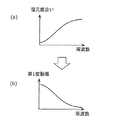
復元関数は、撮影時の画像のボケあるいはブレなどを表すPSF(Point Spread Function)から導出される。最も原始的には、復元関数は、PSFの逆関数で表され、図5の(a)に示すような特徴を持っている。なお、復元関数は、必ずしもPSFの逆関数である必要はなく、PSFの逆関数に近似する変換関数であってもよい。 The restoration function is derived from a PSF (Point Spread Function) representing blurring or blurring of an image at the time of shooting. Most primitively, the restoration function is represented by an inverse function of PSF, and has a characteristic as shown in FIG. Note that the restoration function is not necessarily an inverse function of PSF, and may be a conversion function approximating the inverse function of PSF.
図5は、本発明の実施の形態1に係る第1変動幅設定部12における処理を説明するための図である。具体的には、図5の(a)は復元関数の一例を示す図であり、図5の(b)は第1変動幅の一例を示す図である。
FIG. 5 is a diagram for explaining processing in the first fluctuation
入力画像にぼやけが生じている場合、入力画像の高周波数成分が減衰され、入力画像の細部あるいはエッジなどがくっきりしていない。そのため、入力画像を復元するためには、高周波成分を強調する必要がある。そこで、復元関数は、一般的に、図5の(a)に示すように設定される。つまり、復元関数は、高周波数ほど復元度合いが大きくなうように設定される。ここで、ノイズ低減部11がノイズ低減処理を行った際に画像の劣化が発生した場合は、この画像の劣化も画像復元処理によって強調されてしまう。
When the input image is blurred, the high frequency components of the input image are attenuated, and details or edges of the input image are not clear. Therefore, in order to restore the input image, it is necessary to emphasize the high frequency component. Therefore, the restoration function is generally set as shown in FIG. That is, the restoration function is set so that the degree of restoration increases as the frequency increases. Here, when image degradation occurs when the
そこで、画像復元処理によって、ノイズ低減処理で発生した画像の劣化が強調されないように、第1変動幅設定部12は、復元度合いが大きい周波数ほど当該周波数における第1変動幅が小さくなるように、第1変動幅を周波数ごとに設定する。
Therefore, the first fluctuation
例えば周波数ごとの第1変動幅をRange(u,v)と表した場合、Range(u,v)は、図5の(b)に示すように、周波数が高いほど値が小さくなるように設定される。具体的には、Range(u,v)は、例えば、予め定められた一定値から復元度合いを示す値を減じることにより算出される。また例えば、Range(u,v)は、予め定められた一定値を、復元度合いを示す値で除算することにより算出されてもよい。つまり、Range(u,v)は、復元度合いが大きいほど値が小さくなるように算出されれば、どのような方法で算出されてもよい。 For example, when the first fluctuation range for each frequency is expressed as Range (u, v), Range (u, v) is set so that the value decreases as the frequency increases, as shown in FIG. Is done. Specifically, Range (u, v) is calculated, for example, by subtracting a value indicating the degree of restoration from a predetermined constant value. For example, Range (u, v) may be calculated by dividing a predetermined constant value by a value indicating the degree of restoration. That is, Range (u, v) may be calculated by any method as long as the value is calculated to be smaller as the degree of restoration is larger.
次に、周波数制限部13は、第1変動幅設定部12によって設定された第1変動幅に従って、ノイズ低減部11によってノイズが低減されたノイズ低減画像を加工する(S104)。ステップS104の処理の詳細は、図6を用いて後述する。
Next, the
最後に、復元処理部20は、ぼやけを低減する画像復元処理をノイズ処理画像に対して行い(S105)、処理を終了する。
Finally, the
以下、周波数制限部13における処理(S104)について、図6を用いて詳細に説明する。
Hereinafter, the process (S104) in the
図6は、本発明の実施の形態1に係る周波数制限部13における処理の流れを示すフローチャートである。
FIG. 6 is a flowchart showing the flow of processing in the
まず、領域変換部13aは、入力画像及びノイズ低減画像をフーリエ変換で周波数領域に変換し、入力画像及びノイズ低減画像の振幅特性A1(u,v)及びA2(u,v)を算出する(S131)。そして、比較部13bは、周波数ごとに振幅特性A1(u,v)及びA2(u,v)の比較を行い、以下の式(3)に示すように、振幅の差Diff(u,v)を算出する(S132)。
First, the
![]()
![]()
Diff(u,v)は、ノイズ低減処理後の画像であるノイズ低減画像とノイズ低減処理前の画像である入力画像との周波数領域における振幅の変化度合いを表す。このDiff(u,v)の絶対値は、ノイズ低減処理による画像の変化度合いを示している。Diff(u,v)の絶対値が大きければ、ノイズ低減処理によって、画像が大きく変化したことを意味する。つまり、このDiff(u,v)の絶対値は、入力画像に対するノイズ低減画像の周波数領域における変化度合いを示す変化度に相当する。 Diff (u, v) represents the degree of amplitude change in the frequency domain between the noise-reduced image that is the image after the noise reduction process and the input image that is the image before the noise reduction process. The absolute value of Diff (u, v) indicates the degree of image change due to the noise reduction processing. If the absolute value of Diff (u, v) is large, it means that the image has changed greatly due to the noise reduction processing. That is, the absolute value of Diff (u, v) corresponds to the degree of change indicating the degree of change in the frequency domain of the noise reduced image with respect to the input image.
次に、加工部13cは、算出した振幅の差Diff(u,v)の絶対値及び第1変動幅設定部12が設定した第1変動幅Range(u,v)の大小関係を利用して、周波数領域における変化度合いを制限する(S133)。具体的には、加工部13cは、振幅の差Diff(u,v)の絶対値と変動幅Range(u,v)とを比較する。そして、加工部13cは、振幅の差Diff(u,v)の絶対値が第1変動幅Range(u,v)より大きい場合は、当該周波数において、振幅の差の絶対値が第1変動幅と一致するように、ノイズ低減画像の振幅特性A2(u,v)を加工する。つまり、加工部13cは、ノイズ低減処理によって画像が劣化している可能性があるので、ノイズ低減された画像の振幅数特性A2(u,v)を以下の式(4)により加工する。
Next, the
![]()
![]()
ここで、sign(x)は、xの符号を表す符号関数(signum function)である。 Here, sign (x) is a sign function representing the sign of x.
図7は、本発明の実施の形態1に係るノイズ処理部10によって生成されるノイズ処理画像を説明するための図である。具体的には、図7の(a)は、ノイズ低減部11によって生成されたノイズ低減画像の振幅特性の一例を示す図である。また、図7の(b)は、周波数制限部13によって生成されたノイズ処理画像の振幅特性の一例を示す図である。なお、図7には、u軸方向の一断面の振幅特性を示す。
FIG. 7 is a diagram for explaining a noise processing image generated by the
図7に示すように、周波数制限部13は、ノイズ低減画像において、入力画像の振幅との差分値の絶対値が第1変動幅を超える振幅を、入力画像の振幅と第1変動幅だけ異なる振幅に加工する。このように加工された結果、復元度合いが大きい周波数において振幅の変化度が小さい画像がノイズ処理画像として生成される。
As shown in FIG. 7, the
以上のように、本実施の形態に係る画像処理装置100によれば、画像復元処理を行う前にノイズ処理を行うので、入力画像に含まれるノイズを低減することができ、画像復元処理によってノイズが強調されることを抑制することができる。また、画像復元処理の特性に基づいてノイズ処理を行うので、ノイズ処理によって発生する画像の劣化が画像復元処理によって強調されることを抑制することができる。
As described above, according to the
また、画像処理装置100によれば、復元度合いが大きい周波数ほど当該周波数における変化度合いを制限することができる。したがって、画像の劣化が強調されやすい周波数ほど画像の劣化が発生しないようにノイズ処理を行うことができ、ノイズ処理によって発生する画像の劣化が画像復元処理によって強調されることを効率的に抑制することができる。
Moreover, according to the
なお、本実施の形態では、復元関数は、PSFから導出されたが、必ずしもPSFから導出される必要はない。例えば、復元関数は、カメラの光学系による劣化を表わす劣化関数あるいはカメラの動きによる劣化を表わす劣化関数から導出されてもよい。つまり、復元関数は、入力画像の劣化を表す劣化関数から導出されればよい。 In the present embodiment, the restoration function is derived from the PSF, but it is not necessarily derived from the PSF. For example, the restoration function may be derived from a degradation function that represents degradation due to the camera optical system or a degradation function that represents degradation due to camera motion. That is, the restoration function may be derived from a degradation function that represents degradation of the input image.
なお、本実施の形態では、第1変動幅設定部12では、図5の(b)に示すに第1変動幅を設定したが、復元度合いが大きいほど第1変動幅を小さくするという条件を満たしていれば、必ずしも同図に示すように第1変動幅を設定する必要はない。また、第1変動幅設定部12は、さらに、第1変動幅が予め定められた上限値及び下限値の範囲内の値となるように、第1変動幅を設定してもよい。
In the present embodiment, the first fluctuation
なお、本実施の形態では、領域変換部13aは、画像を周波数領域に変換する際にフーリエ変換を利用したが、画像を周波数領域に変換できれば、他の変換方法を利用してもよい。
In the present embodiment, the
(実施の形態2)
次に、本発明の実施の形態2について説明する。
(Embodiment 2)
Next, a second embodiment of the present invention will be described.
本実施の形態に係る画像処理装置は、実施の形態1に係る画像処理装置とノイズ処理部10の一部が異なるが、他の部分については同様である。そこで、実施の形態1と異なる部分を中心に実施の形態2について、図面を参照しながら説明する。
The image processing apparatus according to the present embodiment is different from the image processing apparatus according to the first embodiment in part of the
図8は、本発明の実施の形態2に係るノイズ処理部10の機能構成を示すブロック図である。図8において、図2と同じ構成要素については同じ符号を用い、適宜、説明を省略する。
FIG. 8 is a block diagram showing a functional configuration of the
ノイズ周波数特性算出部14は、入力画像及びノイズ情報を利用して、ノイズの周波数特性を算出する。
The noise frequency
第2変動幅設定部15は、ノイズ周波数特性算出部14により算出されたノイズの周波数特性に基づいて、周波数に関わらず均一の第2変動幅を設定する。
The second fluctuation
まず、ノイズ周波数特性算出部14における処理の詳細を説明する。
First, details of the processing in the noise frequency
一般に画像に含まれるランダム性のノイズは、画像の輝度が一定の場合は、全ての周波数において振幅がほぼ同じという特性がある。また、撮影時のISO感度が高められることによって、撮影画像がゲインアップされ、ノイズも増幅される。ここで、平均輝度及びISO感度の組み合わせが互い異なる複数の画像においてノイズ量が予め算出されていれば、平均輝度とISO感度とにノイズの周波数特性(例えば振幅の最大値)を対応付けたテーブルを生成することができる。 In general, random noise included in an image has a characteristic that the amplitude is almost the same at all frequencies when the luminance of the image is constant. Further, the ISO sensitivity at the time of shooting is increased, so that the shot image is gained up and noise is also amplified. Here, if the amount of noise is calculated in advance for a plurality of images having different combinations of average luminance and ISO sensitivity, a table in which the average luminance and ISO sensitivity are associated with noise frequency characteristics (for example, maximum amplitude). Can be generated.
この場合、ノイズ周波数特性算出部14は、テーブルを参照することによって、カメラのセンサー特性、入力画像領域の平均輝度及び撮影時のISO感度情報に対応するノイズの周波数特性を算出できる。つまり、ノイズ周波数特性算出部14は、カメラのセンサー特性、入力画像領域の平均輝度及び撮影時のISO感度情報に対応する、周波数領域におけるノイズの振幅の最大値を算出できる。
In this case, the noise frequency
そこで、ノイズ周波数特性算出部14は、まず入力画像の平均輝度を算出する。そして、ノイズ周波数特性算出部14は、予め保存されているテーブルを参照して、算出した平均輝度及び取得したISO情報に対応する、周波数領域におけるノイズの振幅の最大値N_maxを算出する。
Therefore, the noise frequency
次に、第2変動幅設定部15における処理の詳細を説明する。
Next, details of the processing in the second fluctuation
ここで、入力画像をF(u,v)、真の画像信号をS(u,v)、ノイズをN(u,v)と表した場合、入力画像は以下の式(5)のように表される。 Here, when the input image is represented as F (u, v), the true image signal is represented as S (u, v), and the noise is represented as N (u, v), the input image is represented by the following equation (5). expressed.
![]()
![]()
また、算出されたノイズの振幅の最大値はN_maxである。したがって、図9に示すように、各周波数成分において、真の画像信号S(u,v)は、(F(u,v)±N_max)の範囲(ハッチングされた領域)で変動することがわかる。つまり、ノイズ低減画像が、この範囲(ハッチングされた領域)を超えた場合は、真の画像信号がノイズ低減処理によって劣化されたことがわかる。 Further, the maximum value of the calculated noise amplitude is N_max. Therefore, as shown in FIG. 9, it can be seen that the true image signal S (u, v) varies in a range (hatched area) of (F (u, v) ± N_max) in each frequency component. . That is, when the noise-reduced image exceeds this range (hatched area), it can be seen that the true image signal has been degraded by the noise reduction process.
そこで、入力画像の劣化を抑制するために、第2変動幅設定部15は、周波数に関わらず均一な第2変動幅として、ノイズの振幅の最大値N_maxを設定する。
Therefore, in order to suppress deterioration of the input image, the second fluctuation
次に、周波数制限部13は、入力画像に対するノイズ処理画像の周波数領域における変化度合いを示す変化度が第1変動幅及び第2変動幅を超えないようにノイズ低減画像を加工する。
Next, the
具体的には、周波数制限部13は、例えば、第2変動幅設定部15が設定した第2変動幅N_maxを利用して、第1変動幅設定部12が設定した第1変動幅Range(u,v)を補正する。
Specifically, the
第1変動幅Range(u,v)は、ノイズ特性を利用せず算出された値であるため、実際のノイズよりも大きな変化度合いを許容する値である可能性がある。そこで、周波数制限部13は、Range(u,v)の最大値がN_maxになるようにRange(u,v)を補正する。具体的には、周波数制限部13は、例えば、Range(u,v)の最大値がN_maxになるようにスケール処理する。また例えば、周波数制限部13は、Range(u,v)のうちN_maxを超える部分がN_maxと一致するように、Range(u,v)を補正してもよい。そして、周波数制限部13は、補正したRange(u,v)を利用して実施の形態1と同様の処理を行う。
Since the first fluctuation range Range (u, v) is a value calculated without using the noise characteristics, there is a possibility that the first variation range Range (u, v) allows a greater degree of change than the actual noise. Therefore, the
以上のように、本実施の形態に係る画像処理装置100によれば、ノイズの情報を利用してノイズの周波数特性を算出することによって、ノイズの振幅の最大値を正確に推定することができる。このノイズの振幅の最大値を利用して、入力画像に対するノイズ処理画像の周波数領域における変化度合いを制限することによって、ノイズ処理による画像の劣化を抑制することができる。
As described above, according to the
なお、本実施の形態では、ノイズ周波数特性算出部14では、入力画像の平均輝度を算出したが、ノイズ低減画像の平均輝度を算出してもよい。これは、ノイズ低減処理によって平均輝度はほとんど変化しないからである。
In the present embodiment, the noise frequency
なお、本実施の形態では、ノイズ周波数特性算出部14は、平均輝度とISO感度とにノイズの振幅の最大値を対応付けたテーブルを用いて、ノイズの振幅の最大値を算出していたが、必ずしもテーブルを用いてノイズの振幅の最大値を算出する必要はない。例えば、ノイズ周波数特性算出部14は、平均輝度とISO感度とからノイズの振幅の最大値を算出することができる数式を用いて、ノイズの振幅の最大値を算出してもよい。
In the present embodiment, the noise frequency
なお、本実施の形態では、ノイズ周波数特性算出部14は、画像全体に対してノイズの周波数特性を算出したが、画像領域ごとにノイズの周波数特性を算出してもよい。これによれば、ノイズ周波数特性算出部14は、画像領域の平均輝度がより正確に求められ、それに伴って、ノイズの周波数特性もより正確に算出できる。
In the present embodiment, the noise frequency
なお、本実施の形態では、周波数制限部13は、第2変動幅を用いて第1変動幅を補正していたが、必ずしも第1変動幅を補正する必要はない。この場合、周波数制限部13は、例えば、第1変動幅及び第2変動幅を順に用いて変化度合いを制限してもよい。具体的には、周波数制限部13は、例えば、第1変動幅を用いてノイズ低減画像を加工した後、加工後の画像を第2変動幅を用いて加工してもよい。
In the present embodiment, the
以上、本発明の一態様に係る画像処理装置100について、実施の形態に基づいて説明したが、本発明は、これらの実施の形態に限定されるものではない。本発明の趣旨を逸脱しない限り、当業者が思いつく各種変形を本実施の形態に施したもの、あるいは異なる実施の形態における構成要素を組み合わせて構築される形態も、本発明の範囲内に含まれる。
The
例えば、上記実施の形態1及び2において、第1変動幅設定部12は、周波数ごとに第1変動幅を設定していたが、必ずしも周波数ごとに第1変動幅を設定する必要はない。例えば、第1変動幅設定部12は、所定の周波数帯域ごとに、第1変動幅を設定してもよい。
For example, in the first and second embodiments, the first fluctuation
また、上記実施の形態1または2における画像処理装置100が備える構成要素の一部または全部は、1個のシステムLSI(Large Scale Integration:大規模集積回路)から構成されているとしてもよい。例えば、画像処理装置100は、図1に示すように、ノイズ処理部10と復元処理部20とを有するシステムLSI101から構成されてもよい。
In addition, some or all of the components included in the
システムLSI101は、複数の構成部を1個のチップ上に集積して製造された超多機能LSIであり、具体的には、マイクロプロセッサ、ROM(Read Only Memory)、RAM(Ramdom Access Memory)などを含んで構成されるコンピュータシステムである。前記RAMには、コンピュータプログラムが記憶されている。前記マイクロプロセッサが、前記コンピュータプログラムに従って動作することにより、システムLSIは、その機能を達成する。
The
なお、ここでは、システムLSIとしたが、集積度の違いにより、IC、LSI、スーパーLSI、ウルトラLSIと呼称されることもある。また、集積回路化の手法はLSIに限るものではなく、専用回路又は汎用プロセッサで実現してもよい。LSI製造後に、プログラムすることが可能なFPGA(Field Programmable Gate Array)、あるいはLSI内部の回路セルの接続や設定を再構成可能なリコンフィギュラブル・プロセッサを利用してもよい。 Although the system LSI is used here, it may be called IC, LSI, super LSI, or ultra LSI depending on the degree of integration. Further, the method of circuit integration is not limited to LSI's, and implementation using dedicated circuitry or general purpose processors is also possible. An FPGA (Field Programmable Gate Array) that can be programmed after manufacturing the LSI, or a reconfigurable processor that can reconfigure the connection and setting of circuit cells inside the LSI may be used.
さらには、半導体技術の進歩又は派生する別技術によりLSIに置き換わる集積回路化の技術が登場すれば、当然、その技術を用いて機能ブロックの集積化を行ってもよい。バイオ技術の適用等が可能性としてありえる。 Further, if integrated circuit technology comes out to replace LSI's as a result of the advancement of semiconductor technology or a derivative other technology, it is naturally also possible to carry out function block integration using this technology. Biotechnology can be applied.
また、本発明は、このような特徴的な処理部を備える画像処理装置として実現することができるだけでなく、画像処理装置に含まれる特徴的な処理部をステップとする画像処理方法として実現することもできる。また、画像処理方法に含まれる特徴的な各ステップをコンピュータに実行させるコンピュータプログラムとして実現することもできる。そして、そのようなコンピュータプログラムは、CD−ROM等のコンピュータ読取可能な非一時的な記録媒体あるいはインターネット等の通信ネットワークを介して流通させることができる。 In addition, the present invention can be realized not only as an image processing apparatus including such a characteristic processing unit, but also as an image processing method using a characteristic processing unit included in the image processing apparatus as a step. You can also. It can also be realized as a computer program that causes a computer to execute the characteristic steps included in the image processing method. Such a computer program can be distributed via a computer-readable non-transitory recording medium such as a CD-ROM or a communication network such as the Internet.
また、本発明は、画像処理装置と撮像素子とを備える撮像装置として実現されてもよい。 In addition, the present invention may be realized as an imaging device including an image processing device and an imaging element.
本発明に係る画像処理装置は、画像のぼやけを低減する際に、画像復元処理の特性に基づいてノイズ低減処理を調整することによって、ノイズを低減しながら画像の劣化を抑制することができる画像処理装置及び画像処理方法として有用である。 An image processing apparatus according to the present invention can suppress image degradation while reducing noise by adjusting noise reduction processing based on characteristics of image restoration processing when reducing blurring of an image. It is useful as a processing device and an image processing method.
10 ノイズ処理部
11 ノイズ低減部
12 第1変動幅設定部
13 周波数制限部
13a 領域変換部
13b 比較部
13c 加工部
14 ノイズ周波数特性算出部
15 第2変動幅設定部
20 復元処理部
100 画像処理装置
101 システムLSI
DESCRIPTION OF
Claims (15)
ノイズを低減するノイズ処理を前記入力画像に対して行うことによりノイズ処理画像を生成するノイズ処理部と、
ぼやけを低減するための復元関数を用いた画像復元処理を前記ノイズ処理画像に対して行う復元処理部とを備え、
前記ノイズ処理部は、前記画像復元処理に用いられる前記復元関数が示す復元度合いが大きいほど前記入力画像に対する前記ノイズ処理画像の変化度合いが制限されるように、前記ノイズ処理を行う、
画像処理装置。 An image processing apparatus for reducing blur caused in an input image,
A noise processing unit that generates a noise processed image by performing noise processing on the input image to reduce noise;
A restoration processing unit that performs image restoration processing on the noise-processed image using a restoration function for reducing blur,
The noise processing unit performs the noise processing so that a degree of change of the noise processed image with respect to the input image is limited as a degree of restoration indicated by the restoration function used for the image restoration processing is larger.
Image processing device.
請求項1に記載の画像処理装置。 The noise processing unit performs the noise processing so that the degree of change in the frequency domain of the noise-processed image with respect to the input image is limited as the degree of restoration is large.
The image processing apparatus according to claim 1.
請求項2に記載の画像処理装置。 The restoration function shows the restoration degree for each frequency in the frequency domain,
The image processing apparatus according to claim 2.
請求項3に記載の画像処理装置。 The noise processing unit performs the noise processing so that the degree of change in the frequency is limited as the restoration degree increases.
The image processing apparatus according to claim 3.
前記入力画像に対して空間領域でノイズ低減処理を行うことにより、ノイズ低減画像を生成するノイズ低減部と、
前記復元度合いが大きい周波数ほど当該周波数における前記変化度合いを制限するための第1変動幅が小さくなるように、第1変動幅を周波数ごとに設定する第1変動幅設定部と、
前記変化度合いの大きさを示す変化度が前記第1変動幅を超えないように前記ノイズ低
減画像を加工することにより、前記ノイズ処理画像を生成する周波数制限部とを有する、
請求項4に記載の画像処理装置。 The noise processing unit
A noise reduction unit that generates a noise reduced image by performing noise reduction processing on the input image in a spatial domain;
A first fluctuation range setting unit that sets the first fluctuation range for each frequency so that the first fluctuation range for limiting the degree of change in the frequency becomes smaller as the restoration degree becomes larger;
A frequency limiting unit that generates the noise-processed image by processing the noise-reduced image so that the change degree indicating the magnitude of the change degree does not exceed the first fluctuation range.
The image processing apparatus according to claim 4.
前記入力画像及び前記ノイズ低減画像を空間領域から周波数領域に変換する領域変換部と、
周波数領域に変換された入力画像の振幅と周波数領域に変換されたノイズ低減画像の振幅との差分値の絶対値を前記変化度として周波数ごとに算出する比較部と、
算出された前記変化度が前記第1変動幅を超えるか否かを周波数ごとに判定し、前記変化度が前記第1変動幅を超えると判定された場合に、当該周波数における前記変化度が前記第1変動幅と一致するように前記ノイズ低減画像の振幅を加工する加工部とを有する、
請求項5に記載の画像処理装置。 The frequency limiter is
An area conversion unit for converting the input image and the noise-reduced image from a spatial domain to a frequency domain;
A comparison unit that calculates the absolute value of the difference value between the amplitude of the input image converted into the frequency domain and the amplitude of the noise reduced image converted into the frequency domain for each frequency as the degree of change;
It is determined for each frequency whether the calculated degree of change exceeds the first fluctuation range, and when it is determined that the degree of change exceeds the first fluctuation range, the degree of change at the frequency is A processing unit that processes the amplitude of the noise-reduced image so as to coincide with the first fluctuation range,
The image processing apparatus according to claim 5.
前記周波数制限部は、前記変化度が前記第1変動幅及び前記第2変動幅を超えないように前記ノイズ低減画像を加工することにより、前記ノイズ処理画像を生成する、
請求項5又は6に記載の画像処理装置。 And a second fluctuation range setting unit for setting a uniform second fluctuation range regardless of the frequency based on the noise information of the input image,
The frequency limiting unit generates the noise processed image by processing the noise reduced image so that the degree of change does not exceed the first fluctuation range and the second fluctuation range.
The image processing apparatus according to claim 5.
請求項7に記載の画像処理装置。 The noise information is calculated using sensor characteristics of the camera, ISO sensitivity when the input image is taken, and luminance of the input image.
The image processing apparatus according to claim 7.
請求項1に記載の画像処理装置。 The noise processing unit performs the noise processing based on the restoration degree and noise information of the input image.
The image processing apparatus according to claim 1.
請求項9に記載の画像処理装置。 The noise information is calculated using sensor characteristics of the camera, ISO sensitivity when the input image is taken, and luminance of the input image.
The image processing apparatus according to claim 9.
請求項1〜10のいずれか1項に記載の画像処理装置。 The restoration function is derived using an image degradation function of the input image.
The image processing apparatus according to claim 1.
請求項1〜11のいずれか1項に記載の画像処理装置。 The image processing device is configured as an integrated circuit,
The image processing apparatus according to claim 1.
ノイズを低減するノイズ処理を前記入力画像に対して行うことによりノイズ処理画像を生成するノイズ処理ステップと、
ぼやけを低減するための復元関数を用いた画像復元処理を前記ノイズ処理画像に対して行う復元処理ステップとを含み、
前記ノイズ処理ステップにおいて、前記画像復元処理に用いられる前記復元関数が示す復元度合いが大きいほど前記入力画像に対する前記ノイズ処理画像の変化度合いが制限されるように、前記ノイズ処理を行う、
画像処理方法。 An image processing method for reducing blur caused in an input image,
A noise processing step for generating a noise processed image by performing noise processing on the input image to reduce noise;
A restoration processing step of performing an image restoration process using a restoration function for reducing blur on the noise-processed image,
In the noise processing step, the noise processing is performed so that a degree of change of the noise processed image with respect to the input image is limited as a degree of restoration indicated by the restoration function used in the image restoration processing is larger.
Image processing method.
Priority Applications (5)
| Application Number | Priority Date | Filing Date | Title |
|---|---|---|---|
| JP2010196231A JP5672527B2 (en) | 2010-09-01 | 2010-09-01 | Image processing apparatus and image processing method |
| US13/503,400 US8830362B2 (en) | 2010-09-01 | 2011-08-31 | Image processing apparatus and image processing method for reducing image blur in an input image while reducing noise included in the input image and restraining degradation of the input image caused by the noise reduction |
| EP11821317.2A EP2613516B1 (en) | 2010-09-01 | 2011-08-31 | Image processing device and image processing method |
| PCT/JP2011/004854 WO2012029296A1 (en) | 2010-09-01 | 2011-08-31 | Image processing device and image processing method |
| CN201180004277.6A CN102598649B (en) | 2010-09-01 | 2011-08-31 | Image processing apparatus and image processing method |
Applications Claiming Priority (1)
| Application Number | Priority Date | Filing Date | Title |
|---|---|---|---|
| JP2010196231A JP5672527B2 (en) | 2010-09-01 | 2010-09-01 | Image processing apparatus and image processing method |
Publications (3)
| Publication Number | Publication Date |
|---|---|
| JP2012054795A JP2012054795A (en) | 2012-03-15 |
| JP2012054795A5 JP2012054795A5 (en) | 2013-04-11 |
| JP5672527B2 true JP5672527B2 (en) | 2015-02-18 |
Family
ID=45772420
Family Applications (1)
| Application Number | Title | Priority Date | Filing Date |
|---|---|---|---|
| JP2010196231A Active JP5672527B2 (en) | 2010-09-01 | 2010-09-01 | Image processing apparatus and image processing method |
Country Status (4)
| Country | Link |
|---|---|
| US (1) | US8830362B2 (en) |
| EP (1) | EP2613516B1 (en) |
| JP (1) | JP5672527B2 (en) |
| WO (1) | WO2012029296A1 (en) |
Families Citing this family (8)
| Publication number | Priority date | Publication date | Assignee | Title |
|---|---|---|---|---|
| CN102721465B (en) * | 2012-06-13 | 2014-02-05 | 江苏省电力公司南京供电公司 | System and method for diagnosing and preliminarily positioning loosening faults of iron core of power transformer |
| AU2012258467A1 (en) * | 2012-12-03 | 2014-06-19 | Canon Kabushiki Kaisha | Bokeh amplification |
| JP6318520B2 (en) | 2013-09-27 | 2018-05-09 | 株式会社リコー | Imaging apparatus, imaging system, and imaging method |
| JP2015097382A (en) * | 2013-10-08 | 2015-05-21 | キヤノン株式会社 | Information processing device, imaging system, information processing method and program |
| JP6611543B2 (en) * | 2015-10-05 | 2019-11-27 | キヤノン株式会社 | Image processing apparatus, image processing method, and program |
| DE102016206559B3 (en) * | 2016-04-19 | 2017-06-08 | Siemens Healthcare Gmbh | Method for correcting an X-ray image for effects of a scattered radiation grid, X-ray device, computer program and electronically readable data carrier |
| JP6564158B2 (en) * | 2017-06-05 | 2019-08-21 | 楽天株式会社 | Image processing apparatus, image processing method, and image processing program |
| CN111989910B (en) | 2018-04-12 | 2021-12-14 | 三菱电机株式会社 | Image processing apparatus, image processing method, and recording medium having image processing program recorded thereon |
Family Cites Families (13)
| Publication number | Priority date | Publication date | Assignee | Title |
|---|---|---|---|---|
| JP3173131B2 (en) * | 1992-06-15 | 2001-06-04 | ソニー株式会社 | Digital video signal processor |
| JPH08172533A (en) | 1994-12-20 | 1996-07-02 | Olympus Optical Co Ltd | Image processor |
| EP1168243B1 (en) * | 1995-09-29 | 2004-06-09 | Fuji Photo Film Co., Ltd. | Image processing method and apparatus |
| JP4661238B2 (en) * | 2005-01-31 | 2011-03-30 | コニカミノルタホールディングス株式会社 | Image processing method, image processing apparatus, and image processing program |
| JP4712631B2 (en) | 2005-07-28 | 2011-06-29 | 京セラ株式会社 | Imaging device |
| JP2007067625A (en) | 2005-08-30 | 2007-03-15 | Matsushita Electric Ind Co Ltd | Filter correction circuit in camera system |
| JP4837365B2 (en) * | 2005-11-16 | 2011-12-14 | オリンパス株式会社 | Image processing system and image processing program |
| JP2007179211A (en) * | 2005-12-27 | 2007-07-12 | Matsushita Electric Ind Co Ltd | Image processing device, image processing method, and program for it |
| JP2007322560A (en) * | 2006-05-30 | 2007-12-13 | Kyocera Corp | Imaging apparatus, and apparatus and method of manufacturing the same |
| US8184926B2 (en) * | 2007-02-28 | 2012-05-22 | Microsoft Corporation | Image deblurring with blurred/noisy image pairs |
| JP2009089228A (en) * | 2007-10-02 | 2009-04-23 | Sanyo Electric Co Ltd | Imaging apparatus |
| US8120679B2 (en) * | 2008-08-01 | 2012-02-21 | Nikon Corporation | Image processing method |
| JP5447867B2 (en) * | 2008-08-08 | 2014-03-19 | 学校法人東京理科大学 | Image restoration apparatus and image restoration method |
-
2010
- 2010-09-01 JP JP2010196231A patent/JP5672527B2/en active Active
-
2011
- 2011-08-31 WO PCT/JP2011/004854 patent/WO2012029296A1/en active Application Filing
- 2011-08-31 EP EP11821317.2A patent/EP2613516B1/en active Active
- 2011-08-31 US US13/503,400 patent/US8830362B2/en active Active
Also Published As
| Publication number | Publication date |
|---|---|
| US20120206630A1 (en) | 2012-08-16 |
| EP2613516B1 (en) | 2017-10-25 |
| EP2613516A4 (en) | 2015-01-21 |
| CN102598649A (en) | 2012-07-18 |
| US8830362B2 (en) | 2014-09-09 |
| EP2613516A1 (en) | 2013-07-10 |
| WO2012029296A1 (en) | 2012-03-08 |
| JP2012054795A (en) | 2012-03-15 |
Similar Documents
| Publication | Publication Date | Title |
|---|---|---|
| JP5672527B2 (en) | Image processing apparatus and image processing method | |
| US9324153B2 (en) | Depth measurement apparatus, image pickup apparatus, depth measurement method, and depth measurement program | |
| US7876973B2 (en) | Edge ringing artifact suppression methods and apparatuses | |
| US10002411B2 (en) | Image processing apparatus, image pickup apparatus, image processing method, and non-transitory computer-readable storage medium for estimating blur | |
| US8983221B2 (en) | Image processing apparatus, imaging apparatus, and image processing method | |
| US20110033132A1 (en) | Image correction apparatus and image correction method | |
| JP4856293B2 (en) | Imaging apparatus and image restoration method | |
| JP4847633B2 (en) | Imaging apparatus and image restoration method | |
| JP5983373B2 (en) | Image processing apparatus, information processing method, and program | |
| JP2008146643A (en) | Method and device for reducing blur caused by movement in image blurred by movement, and computer-readable medium executing computer program for reducing blur caused by movement in image blurred by movement | |
| US20100054590A1 (en) | Information Processing Apparatus, Information Processing Method, and Program | |
| US20110158541A1 (en) | Image processing device, image processing method and program | |
| EP2564373B1 (en) | Detection and/or enhancement of contrast differences in digital image data | |
| US10217193B2 (en) | Image processing apparatus, image capturing apparatus, and storage medium that stores image processing program | |
| US9947083B2 (en) | Image processing method, image processing apparatus, image capturing apparatus, image processing program and non-transitory computer-readable storage medium | |
| JP5914843B2 (en) | Image processing apparatus and image processing method | |
| CN115496673A (en) | Image processing method, image processing apparatus, image processing system, and storage medium | |
| JP2010009348A (en) | Image processor, processing method, and program | |
| JP2007179211A (en) | Image processing device, image processing method, and program for it | |
| JP6256680B2 (en) | Image processing method, image processing apparatus, and image processing program | |
| JP2023058758A (en) | Data generating method, learning method, estimating method, data generating device, and program | |
| JP5863236B2 (en) | Image processing apparatus and image processing method | |
| JP5761195B2 (en) | Image processing apparatus, image processing program, and image processing method | |
| EP2309448A1 (en) | Local image contrast enhancement | |
| JP2017027463A (en) | Image processing unit, imaging apparatus, image processing method, image processing program, and storage medium |
Legal Events
| Date | Code | Title | Description |
|---|---|---|---|
| A521 | Request for written amendment filed |
Free format text: JAPANESE INTERMEDIATE CODE: A523 Effective date: 20130225 |
|
| A621 | Written request for application examination |
Free format text: JAPANESE INTERMEDIATE CODE: A621 Effective date: 20130225 |
|
| A131 | Notification of reasons for refusal |
Free format text: JAPANESE INTERMEDIATE CODE: A131 Effective date: 20140304 |
|
| A521 | Request for written amendment filed |
Free format text: JAPANESE INTERMEDIATE CODE: A523 Effective date: 20140423 |
|
| A711 | Notification of change in applicant |
Free format text: JAPANESE INTERMEDIATE CODE: A711 Effective date: 20141007 |
|
| TRDD | Decision of grant or rejection written | ||
| A01 | Written decision to grant a patent or to grant a registration (utility model) |
Free format text: JAPANESE INTERMEDIATE CODE: A01 Effective date: 20141202 |
|
| A61 | First payment of annual fees (during grant procedure) |
Free format text: JAPANESE INTERMEDIATE CODE: A61 Effective date: 20141211 |
|
| R151 | Written notification of patent or utility model registration |
Ref document number: 5672527 Country of ref document: JP Free format text: JAPANESE INTERMEDIATE CODE: R151 |