JP5670476B2 - Image capture device with tilt or perspective correction capability - Google Patents
Image capture device with tilt or perspective correction capability Download PDFInfo
- Publication number
- JP5670476B2 JP5670476B2 JP2012545944A JP2012545944A JP5670476B2 JP 5670476 B2 JP5670476 B2 JP 5670476B2 JP 2012545944 A JP2012545944 A JP 2012545944A JP 2012545944 A JP2012545944 A JP 2012545944A JP 5670476 B2 JP5670476 B2 JP 5670476B2
- Authority
- JP
- Japan
- Prior art keywords
- image
- data
- processors
- instructions
- capture device
- Prior art date
- Legal status (The legal status is an assumption and is not a legal conclusion. Google has not performed a legal analysis and makes no representation as to the accuracy of the status listed.)
- Active
Links
- 238000012937 correction Methods 0.000 title description 14
- 238000005259 measurement Methods 0.000 claims description 38
- 238000000034 method Methods 0.000 claims description 13
- 230000001413 cellular effect Effects 0.000 description 5
- 238000012986 modification Methods 0.000 description 4
- 230000004048 modification Effects 0.000 description 4
- XIWFQDBQMCDYJT-UHFFFAOYSA-M benzyl-dimethyl-tridecylazanium;chloride Chemical compound [Cl-].CCCCCCCCCCCCC[N+](C)(C)CC1=CC=CC=C1 XIWFQDBQMCDYJT-UHFFFAOYSA-M 0.000 description 3
- 238000003825 pressing Methods 0.000 description 3
- 230000009466 transformation Effects 0.000 description 3
- 238000010586 diagram Methods 0.000 description 2
- 238000012805 post-processing Methods 0.000 description 2
- 230000001133 acceleration Effects 0.000 description 1
- 230000003213 activating effect Effects 0.000 description 1
- 230000000295 complement effect Effects 0.000 description 1
- 238000009432 framing Methods 0.000 description 1
- 230000006870 function Effects 0.000 description 1
- 230000005484 gravity Effects 0.000 description 1
- 229910044991 metal oxide Inorganic materials 0.000 description 1
- 150000004706 metal oxides Chemical class 0.000 description 1
- 239000004065 semiconductor Substances 0.000 description 1
Images


Classifications
-
- G06T5/80—
-
- H—ELECTRICITY
- H04—ELECTRIC COMMUNICATION TECHNIQUE
- H04N—PICTORIAL COMMUNICATION, e.g. TELEVISION
- H04N23/00—Cameras or camera modules comprising electronic image sensors; Control thereof
- H04N23/60—Control of cameras or camera modules
- H04N23/68—Control of cameras or camera modules for stable pick-up of the scene, e.g. compensating for camera body vibrations
-
- G—PHYSICS
- G06—COMPUTING; CALCULATING OR COUNTING
- G06T—IMAGE DATA PROCESSING OR GENERATION, IN GENERAL
- G06T3/00—Geometric image transformation in the plane of the image
- G06T3/60—Rotation of a whole image or part thereof
-
- H—ELECTRICITY
- H04—ELECTRIC COMMUNICATION TECHNIQUE
- H04N—PICTORIAL COMMUNICATION, e.g. TELEVISION
- H04N23/00—Cameras or camera modules comprising electronic image sensors; Control thereof
- H04N23/60—Control of cameras or camera modules
- H04N23/63—Control of cameras or camera modules by using electronic viewfinders
- H04N23/633—Control of cameras or camera modules by using electronic viewfinders for displaying additional information relating to control or operation of the camera
- H04N23/635—Region indicators; Field of view indicators
-
- H—ELECTRICITY
- H04—ELECTRIC COMMUNICATION TECHNIQUE
- H04N—PICTORIAL COMMUNICATION, e.g. TELEVISION
- H04N23/00—Cameras or camera modules comprising electronic image sensors; Control thereof
- H04N23/60—Control of cameras or camera modules
- H04N23/68—Control of cameras or camera modules for stable pick-up of the scene, e.g. compensating for camera body vibrations
- H04N23/681—Motion detection
- H04N23/6815—Motion detection by distinguishing pan or tilt from motion
Description
本発明は、一般的に、電子システムの画像捕獲装置に係り、より詳細には、傾斜及び/又は遠近歪を修正する能力を有する画像捕獲装置に係る。 The present invention relates generally to image capture devices for electronic systems, and more particularly to image capture devices having the ability to correct tilt and / or perspective distortion.
関連出願の相互参照:本特許協力条約の特許出願は、2010年12月22日に出願された“IMAGE CAPTURE DEVICE HAVING TILT AND/OR PERSPECTIVE CORRECTION”と題する米国ノンプロビジョナル出願第12/644,800号の優先権を主張するもので、その内容は、参考としてここにそのまま援用される。 Cross-reference of related applications: Patent application of this Patent Cooperation Treaty is a US non-provisional application No. 12 / 644,800 entitled “IMAGE CAPTURE DEVICE HAVING TILT AND / OR PERSPECTIVE CORRECTION” filed on December 22, 2010. The contents of which are incorporated herein by reference in their entirety.
電子装置は、社会に偏在し、腕時計からコンピュータに至るまであらゆるものに見ることができる。多くの電子装置は、今や、画像捕獲装置を一体化しており、従って、これら電子装置のユーザは、準備なしに撮影できる能力を有している。例えば、ユーザがカメラを所持していないが、一体型の画像捕獲装置を備えたセルラーホン又は他のパーソナルメディア装置を有している場合には、ユーザは、一緒に撮影する機会を見合わせるのではなく、撮影を行うことができる。これらの電子装置を使用して撮影を行う能力は、好都合ではあるが、ユーザにとってこれらの電子装置を安定させ及び/又はそれらを水平に保って撮影することがしばしば困難である。撮影中電子装置を安定にさせ及び/又は水平に保つ能力に欠けることで、多くの場合に、歪が生じて、画像が傾斜したり及び/又は遠近感がユーザにとって満足度の低いものになったりする。 Electronic devices are ubiquitous in society and can be found in everything from watches to computers. Many electronic devices now have integrated image capture devices, and thus users of these electronic devices have the ability to take pictures without preparation. For example, if the user does not have a camera but has a cellular phone or other personal media device with an integrated image capture device, the user may not forgive to take a picture together. Without taking pictures. The ability to shoot using these electronic devices is convenient, but it is often difficult for the user to shoot these electronic devices stable and / or keep them horizontal. The lack of the ability to keep the electronic device stable and / or horizontal during shooting often results in distortion, tilting the image and / or making the perspective less satisfactory for the user. Or
実際に、傾斜した写真及び/又は誤った遠近感の写真がカメラから撮影されることもある。例えば、ユーザは、カメラで撮影するときに三脚を有しておらず、従って、ある角度で撮影を行う。カメラを使用して歪んだ写真が生じたか、一体型の画像捕獲装置を有する電装置を使用して歪んだ写真が生じたかに関わらず、多くの場合、後処理によってそれが修正される。不都合なことに、この後処理は、精巧な画像処理ソフトウェア、及び/又は歪を修正するためのユーザによる実質的な関与を必要とする。 In fact, tilted photos and / or wrong perspective photos may be taken from the camera. For example, the user does not have a tripod when shooting with a camera, and therefore takes a picture at an angle. Regardless of whether a distorted photo is produced using a camera or an electrical device having an integrated image capture device is used, it is often corrected by post-processing. Unfortunately, this post processing requires elaborate image processing software and / or substantial user involvement to correct the distortion.
画像捕獲装置の傾斜及び/又は遠近歪を部分的又は完全に修正又は補償するための方法及び装置が開示される。ある実施形態において、この方法は、物体に対する画像捕獲装置の相対的位置に関連した方向測定値を読み取り、その方向測定値がスレッシュホールドより小さいかどうか決定し、そしてその方向測定値がスレッシュホールドより小さい場合には、画像捕獲装置により得られた画像を修正することを含む。 A method and apparatus for partially or fully correcting or compensating for tilt and / or perspective distortion of an image capture device is disclosed. In some embodiments, the method reads a directional measurement associated with the relative position of the image capture device with respect to the object, determines whether the directional measurement is less than the threshold, and the directional measurement is less than the threshold. If small, it involves modifying the image obtained by the image capture device.
他の実施形態は、画像センサ、画像センサに結合されたメモリ、画像センサに結合された方向測定装置、及び画像センサに結合された距離測定装置を有する画像捕獲装置を包含する。センサにより捕獲された画像データは、加速度計からの測定値及び/又は距離測定装置からの測定値と共にメモリに記憶される。 Other embodiments include an image capture device having an image sensor, a memory coupled to the image sensor, a direction measuring device coupled to the image sensor, and a distance measuring device coupled to the image sensor. Image data captured by the sensor is stored in memory along with measurements from the accelerometer and / or measurements from the distance measuring device.
更に別の実施形態は、画像歪を修正する方法において、画像捕獲装置と写真撮影される物体との間の距離に関連した距離測定値を距離測定装置から読み取り、画像捕獲装置に関連した方向測定値を読み取り、そしてその距離測定値及び方向測定値を使用して、写真撮影される物体を表わす画像データを修正することを含む方法の形態である。 Yet another embodiment is a method for correcting image distortion, in which a distance measurement related to the distance between an image capture device and a photographed object is read from the distance measurement device and a direction measurement associated with the image capture device. A form of a method that includes reading a value and using the distance and direction measurements to modify image data representing the object being photographed.
異なる図面に同じ参照番号が使用されているのは、同様又は同じ品目を示している。 The use of the same reference numbers in different drawings indicates similar or identical items.
画像捕獲装置で撮影された写真の傾斜及び/又は遠近歪を電子装置で修正できるようにする電子装置の実施形態が開示される。ここに使用する「画像捕獲装置」という語は、スチール写真及び/又はビデオを撮影する能力を有する電子装置を指すものとする。このような電子装置は、デジタルカメラ、及び一体型カメラを伴う消費者向け電子装置(例えば、セルラーホン又はパーソナルメディアプレーヤ)を含む。又、ここで使用する「写真」という語は、ユーザにより記憶のために選択された画像を指すものとする。ここに開示する画像捕獲装置は、写真撮影される物体に対する画像捕獲装置の物理的方向データを記録する加速度計及び/又は距離測定センサを含む。この方向データは、画像捕獲装置により撮影された写真及び/又はビデオの歪を修正するのに使用される。又、方向データは、画像捕獲装置により撮影された写真及び/又はビデオの遠近歪を修正するために距離データに関連して使用することもできる。ある実施形態では、この修正は、写真及び/又はビデオが撮影されるときに画像捕獲装置によりオンザフライで行われる。他の実施形態では、この修正は、撮影後に写真及び/又はビデオに対して行われる。このようなケースでは、方向及び/又は距離データは、後で使用するために写真及び/又はビデオを記録するのに使用される画像データファイルに埋め込まれる。更に別の実施形態では、画像捕獲装置は、方向データ及び/又は距離データを使用して、歪のレベルをユーザに双方向指示し、ユーザが画像捕獲装置の物理的方向を調整して歪を修正できるようにする。例えば、ある実施形態では、カメラを水平にするのに必要なアクションを示すために動的な切り落とし線又はバーチャルレベルがユーザに表示される。 Embodiments of an electronic device are disclosed that allow an electronic device to correct tilt and / or perspective distortion of a photograph taken with an image capture device. As used herein, the term “image capture device” is intended to refer to an electronic device having the ability to take still pictures and / or videos. Such electronic devices include digital cameras and consumer electronic devices (eg, cellular phones or personal media players) with integrated cameras. Also, the term “photo” as used herein refers to an image selected for storage by the user. The image capture device disclosed herein includes an accelerometer and / or a distance measurement sensor that records physical orientation data of the image capture device relative to the object being photographed. This direction data is used to correct distortions in the photos and / or videos taken by the image capture device. The direction data can also be used in conjunction with the distance data to correct perspective distortion of photographs and / or videos taken by the image capture device. In certain embodiments, this modification is performed on-the-fly by the image capture device when a photograph and / or video is taken. In other embodiments, this modification is made to the photos and / or videos after shooting. In such cases, the direction and / or distance data is embedded in an image data file that is used to record photos and / or videos for later use. In yet another embodiment, the image capture device uses direction data and / or distance data to interactively indicate the level of distortion to the user, and the user adjusts the physical direction of the image capture device to correct the distortion. Allow correction. For example, in one embodiment, a dynamic cutoff line or virtual level is displayed to the user to indicate the action required to level the camera.
ここに開示する1つ以上の実施形態は、特定の電子装置を参照して詳細に説明するが、それら実施形態は、請求の範囲を含めて本開示の範囲を限定するものとして解釈又は使用されてはならない。更に、当業者であれば、以下の説明は、広く適用できることが理解されよう。例えば、ここに開示する実施形態は、カメラ又はセルラーホンのようなあるポータブル電子装置に焦点を当てるが、ここに開示される概念は、一体型カメラを合体する他のポータブル電子装置にも等しく適用できることが明らかであろう。例えば、ここに開示される概念は、一体型カメラを伴う腕時計に使用されてもよい。更に、ここに開示される概念は、デスクトップコンピュータのような非ポータブル電子装置にも等しく適用できることが明らかであろう。更に、ここに開示される実施形態は、加速度計及び/又は距離測定センサを使用して歪を修正することに焦点を当てるが、ここに開示される概念は、写真撮影される物体に対して画像捕獲装置の物理的方向を測定する他のセンサにも等しく適用することができる。例えば、ある実施形態では、写真撮影される物体及び画像捕獲装置は、各々、グローバルポジショニングシステム(GPS)装置を含み、物体及び画像捕獲装置の相対的なGPS方向が画像データと共に記録される。又、この開示は、スチール画像に焦点を当てるが、ここに開示される概念は、動画及び/又はビデオの記録にも等しく適用される。従って、これら実施形態の説明は、例示に過ぎず、請求の範囲を含めて本開示の範囲がこれら実施形態に制限されることを示唆するものではない。 One or more embodiments disclosed herein will be described in detail with reference to particular electronic devices, which are to be interpreted or used as limiting the scope of the disclosure, including the claims. must not. Further, those skilled in the art will appreciate that the following description is widely applicable. For example, while the disclosed embodiments focus on certain portable electronic devices such as cameras or cellular phones, the concepts disclosed herein apply equally to other portable electronic devices that incorporate an integrated camera. It will be clear that it can be done. For example, the concepts disclosed herein may be used for watches with integrated cameras. Furthermore, it will be apparent that the concepts disclosed herein are equally applicable to non-portable electronic devices such as desktop computers. Further, while the embodiments disclosed herein focus on correcting distortions using accelerometers and / or distance measuring sensors, the concepts disclosed herein may be applied to objects being photographed. It is equally applicable to other sensors that measure the physical direction of the image capture device. For example, in one embodiment, the object being photographed and the image capture device each include a global positioning system (GPS) device, and the relative GPS directions of the object and the image capture device are recorded along with the image data. This disclosure also focuses on still images, but the concepts disclosed herein apply equally to motion pictures and / or video recording. Therefore, description of these embodiment is only an illustration and does not suggest that the range of this indication including a claim is restrict | limited to these embodiment.
図1Aは、写真の歪を修正するか、又は少なくとも部分的に補償することのできる画像捕獲装置100を示す。図1Bは、画像捕獲装置100のブロック図である。図1A及び1Bは、ある物理的レイアウトを示すが、これは、説明上のものに過ぎないことが明らかである。図1A及び1Bを参照すれば、画像捕獲装置100は、この画像捕獲装置100に入る光の量を制御して、その光を画像センサ120に沿ってレンズ121に通すことのできるアパーチャー110を備えている。画像センサ120の具現化は、実施形態と実施形態との間で異なる。例えば、ある実施形態では、画像センサ120は、相補的金属酸化物半導体センサを使用して具現化される。
FIG. 1A shows an
画像センサ120は、画像捕獲装置100の一般的な動作を制御するプロセッサ130(図1Bに示す)に結合される。ある実施形態では、画像センサ120は、スイッチ125を通して操作され、スイッチ125は、図1Aに示すように画像捕獲装置100に設けられた物理的なスイッチであるか、或いはディスプレイスクリーン170上の容量性制御スイッチである。他の実施形態では、画像センサ120は、スイッチ125なしにプロセッサ130により操作されてもよく、例えば、ディスプレイスクリーン170とは個別に操作されるソフトウェアインターフェイスで操作されてもよい。
The
画像センサ120及びスイッチ125に結合されるのに加えて、プロセッサ130は、1つ以上の方向センサ、例えば、加速度計150及び距離測定センサ155にも結合される。ある実施形態では、加速度計150は、STMicroelectronicsから入手できるLIS302DLモデルのようなマイクロメカニカル三次元加速度計である。他の実施形態では、加速度計150に代わって又は加速度計150に関連して、ジャイロスコープ、慣性基準センサ、及び/又はコンパスが使用される。画像捕獲装置100がX、Y及び/又はZ軸の周りで回転されるときに、加速度計150は、その動きをプロセッサ130に報告する。
In addition to being coupled to the
距離測定センサ155は、音響及び/又は光を各々放射する超音波及び/又は赤外線センサを含むアクティブな自動焦点システムを使用して具現化される。画像捕獲装置100と、写真撮影される物体160との間の距離は、物体160から反射される音響又は光の飛行遅延時間を測定することにより決定される。他の実施形態では、距離測定値は、レンズ121の焦点位置を決定することによって得られ、即ちレンズ121の物理的位置を、物体160と画像捕獲装置100との間の距離に相関させることによって得られる。
The
図1Bに示すように、プロセッサ130は、メモリ165にも結合され、このメモリは、プロセッサ130の指令のもとで、画像データを最適に記憶すると共に、方向及び距離データも記憶する。又、ディスプレイ170は、写真撮影される画像が何に見えるかの考え方を画像捕獲装置100のユーザに与えるために、プロセッサ130に結合される。ある実施形態では、ユーザがスイッチ125を押し、物体160の潜在的な画像がディスプレイ170に表示される。又、画像捕獲装置100は、可聴警報装置190も備え、これは、プロセッサ130に結合され、プロセッサ130の指令のもとで、可聴警報を発生することができる。以下に詳細に述べるように、この可聴警報は、例えば、潜在的な画像が歪を含む場合に、ある情報をユーザに通信するのに使用される。
As shown in FIG. 1B, the
図2A及び2Bは、画像捕獲装置100、特に、セルラーホン又はパーソナルメディア装置のようなハンドヘルド装置の一実施形態を示す。ある実施形態では、図2A及び2Bに示す画像捕獲装置100は、アップル社から入手できるIPHONE移動電話又はIPOD TOUCHポータブルメディアプレーヤである。画像捕獲装置100がIPHONEとして具現化される実施形態では、可聴警報装置190は、IPHONEのスピーカであり、そしてディスプレイ170は、IPHONEのスクリーンである。
2A and 2B illustrate one embodiment of an
画像捕獲装置100の特定の具現化に関わりなく、動作中に、物体160から反射された光がアパーチャー110を経て画像センサ120へ伝達される。画像センサ120は、この入射光を画像データに変換する。ユーザが、例えば、スイッチ125を押すことにより写真を撮影すると、この画像データは、プロセッサ130により、加速度計150からの方向データ及び/又は距離センサ155からの距離データと共にメモリ165に記憶される。方向データとは、一般的に、画像捕獲装置100の、周囲に対する方向に関連したデータを指す。例えば、ある実施形態では、ここに述べる方向データは、X、Y及びZ軸に沿った地球の重力を加速度計150で測定した測定値を指す。他の実施形態では、加速度計150は、画像捕獲装置100が、例えば、乗物において移動しているかどうか決定するのに使用され、そして方向データは、画像捕獲装置100の速度又は加速度を表わす。距離データは、一般的に、画像捕獲装置100と、写真撮影される物体との間の距離を指す。上述したように、距離データは、AF測定の時間の結果、レンズ121の焦点位置の関数であり、或いは画像捕獲装置100と写真撮影される物体とのGPS座標間の相違の結果である。
Regardless of the particular implementation of the
ある実施形態では、方向データ及び/又は距離データは、画像データにリンクされるメタデータとしてメモリ165に記憶される。例えば、ある実施形態では、このデータは、インターナショナルプレステレコミュニケーションズカウンシル(IPTC)フォーマットに適合するフォーマットで記憶され、方向及び距離データが画像データファイルのヘッダの一部分としてメモリ165に記憶されるようにする。他の実施形態では、方向及び距離データは、交換可能な画像ファイルフォーマット(EXIF)で記憶される。例えば、EXIFファイルは、そのEXIFファイル内にカスタムタグを含むように変更され、これらカスタムタグは、加速度計150により記録された3軸方向データ及び/又は距離センサ155により記録された距離αを記憶するものである。
In some embodiments, the direction data and / or distance data is stored in
ある実施形態では、プロセッサ130は、加速度計150により記録された方向データ及び/又は距離センサ155により記録された距離データを利用して、写真撮影時にディスプレイ170上の画像歪をオンザフライで修正する。他の実施形態では、画像捕獲装置100は、写真撮影されようとしている画像に画像歪が存在することをユーザに通知する。
In some embodiments, the
図3A及び3Bは、方向データを使用して歪を修正するために画像捕獲装置100により遂行される2つの一連の動作200、205を示す。そのような歪は、X、Y及び/又はZ方向における画像データの傾斜を含む。動作200は、撮影後の写真を修正するのに適用され、一方、動作205は、写真撮影前に画像を修正するのに適用される。先ず、図1A及び1Bに関連して一連の動作200を参照すれば、動作207において、物体160の写真が撮影されそしてメモリ165に記録される。記憶された写真は、画像データ、並びに方向及び/又は距離データを含む。(距離データを方向データと共に使用して遠近歪を修正することについて以下に詳細に述べる。)動作207の間に写真に関連した画像データを記録するのに加えて、加速度計150からの方向データがメモリ165に記憶される。方向データは、画像データとリンクされる。例えば、ある実施形態では、方向データは、画像データファイルのヘッダに埋め込まれる。この例について続けると、ヘッダは、IPTCフォーマットである。更に、他の実施形態では、方向データは、画像データのタイムスタンプに対応するタイムスタンプと共に記録される。例えば、プロセッサ130は、画像センサ120が物体160の画像を得るときにタイムスタンプを発生し、このタイムスタンプは、方向データがメモリ165に記憶されるときに方向に対して画像データをインデックスするのに使用される。画像データ及び方向データがタイムスタンプでインデックスされるので、それらは、メモリ165内の異なる位置に記憶することができる。これは、プロセッサ130のメモリ管理タスクを簡単にする。メモリ165は、画像捕獲装置100内でローカルに存在してもよいし、或いは画像捕獲装置100に対してリモート位置に存在してもよい。例えば、画像捕獲装置100は、ワイヤレス接続によりリモート記憶位置に画像データを送信することができる。
3A and 3B illustrate two series of
次いで、動作210において、方向データがプロセッサ130により読み取られる。例えば、ある実施形態では、プロセッサ130は、ITPCフォーマットの画像データのヘッダデータを読み取って、方向データを得る。他の実施形態では、画像捕獲装置100の外部のプロセッサによりヘッダデータが読み取られる。ヘッダデータが読み取られるかどうかに関わらず、この読みに基づき、画像捕獲装置100の物理的方向が、例えば、X、Y及び/又はZ軸に対する傾斜角のように、X、Y及び/又はZ軸に対して決定される。
The direction data is then read by the
あるケースでは、画像捕獲装置100のユーザは、物体160の写真を撮るときにX、Y及び/又はZ軸に対して画像捕獲装置100を意図的に傾斜させる。従って、動作210で読み取られる傾斜角は、故意の撮影角を表わす。従って、画像捕獲装置100の故意の傾斜を偶発的な傾斜と見分けるため、プロセッサ130は、方向の読みが、X、Y及び/又はZ軸に対する故意の傾斜に関連したスレッシュホールドより大きいかどうか決定する。ある実施形態では、このスレッシュホールドは、5度である。従って、5度より大きな傾斜は、画像捕獲装置100により意図的なものと解釈され、補償されない。更に、ある実施形態では、このスレッシュホールドは、ユーザによりプログラムすることができる。又、このスレッシュホールドは、X軸がY又はZ軸とは異なるスレッシュホールドを有しそしてY軸がX又はZ軸とは異なるスレッシュホールドを有し、等々のように、X、Y及び/又はZ軸に対して3つの独立したスレッシュホールドを含んでもよい。スレッシュホールドレベルは、自動的に発生され、ユーザの好みに基づきソフトウェアで時間と共に自動的に洗練化され、同様の写真のデータベースを分析することにより決定され、及び/又は他のセンサからの入力に基づいて変更されてもよい(例えば、距離測定値は、更に離れた物体に対してより積極的なスレッシュホールドレベルを指示してもよい)。
In some cases, the user of the
方向データが、選択されたスレッシュホールド値より大きい場合には、動作220で示すように、傾斜がプロセッサ130により意図的であると解釈され、写真は、修正なしにメモリ165に記憶される。他方、方向の読みがスレッシュホールドより小さいとプロセッサ130が決定した場合には、動作225において、写真が修正された後にメモリ165に記憶される。修正動作225は、写真をメモリ165に記憶する前に意図せぬ傾斜を除去するように時計方向及び/又は反時計方向に調整する、等の種々の動作を含む。動作215におけるスレッシュホールドの比較は、複数の次元に異なるスレッシュホールドを含むので、画像捕獲装置100が故意に傾斜された(メモリ165に記憶する前に写真を修正しない)かどうかの最終的な決定は、実施形態ごとに異なる。例えば、ある実施形態では、方向の読みが3つの次元の1つ以上を指示する場合に、写真は、スレッシュホールド値を越える次元において修正される(動作225)。他の実施形態では、3つの次元の2つが各スレッシュホールドより大きいことを方向の読みが指示しない限り、写真は修正されない(動作225)。更に別の実施形態では、3つの全次元が各スレッシュホールドより大きいことを方向の読みが指示しない限り、写真は修正されない(動作225)。更に別の実施形態では、方向スレッシュホールドに関わりなく変換修正フィルタが計算され、この場合は、変換量の限界が計算されて、方向スレッシュホールドに代わって使用される。
If the direction data is greater than the selected threshold value, the slope is interpreted as intentional by the
少なくとも1つの実施形態では、修正動作225は、捕獲画像におけるまっすぐな縁の角度を見積もることを含む。加速度計のデータを適用して捕獲画像をまっすぐにした後に、まっすぐな縁が垂直に非常に近くなった場合には、まっすぐな縁に対してなされた変化を捕獲画像の残部に適用することにより、全捕獲画像が実質的に垂直にされる。従って、これらの実施形態では、まっすぐな縁が垂直にどれほど接近しているか決定するためにスレッシュホールドが使用される。
In at least one embodiment, the
メモリ165に記憶する前に写真を修整するのに加えて、潜在的な写真の画像をユーザに表示するときには、写真をオンザフライで修正することができる。これは、図3Bに示した動作205に例示される。図1A及び1Bに関連して動作205を参照すれば、潜在的な写真の画像が動作230においてディスプレイ170に表示される。これは、ユーザが写真を撮ろうとしていることを示すためにユーザがスイッチ125を押す結果として生じる。加速度計150からの方向データは、動作240の間にプロセッサ130によって読み取られ、そして潜在的な写真の画像が歪を含むかどうか決定するのに使用される。例えば、動作240の間に得られた読みは、ディスプレイ170においてユーザに表示される画像(即ち、潜在的な写真)が歪を含むかどうか、或いはユーザが画像捕獲装置100を故意に傾斜させたかどうか決定するのに使用される。これは、動作250に示されている。動作215の場合と同様に、動作250は、動作240からの方向データの読みを、1つ以上のスレッシュホールド値と比較することにより、画像捕獲装置100が故意に傾斜されたかどうか決定することを含む。加速度計150から読み取られた方向データがスレッシュホールドより大きい場合には、プロセッサ130は、これをユーザによる故意の傾斜と解釈し、そしてディスプレイ170においてユーザに表示される画像の修正を見合わせる。これは、動作260に示されている。動作240の間に読み取られた方向データがスレッシュホールド値より小さい場合には、プロセッサ130は、この画像歪を故意と解釈し、動作270において写真撮影の前に画像に対して修正を行い、そして動作280において、修正された画像がユーザに表示される。このように、ユーザは、写真を撮影する前に修正が充分であるかどうか決定することができる。
In addition to modifying the photo before storing it in
図4A及び4Bは、各々、X軸の歪のある画像の歪及びオンザフライ修正を示す。図4A及び4Bは、説明上、画像のX軸に沿った歪に焦点を当てているが、この説明は、Y軸及び/又はZ軸に沿った歪にも等しく適用される。図4A及び4Bを参照すれば、図4Aは、ディスプレイ170に表示される米国連邦議会議事堂の画像を示している。図4Aを調べることから明らかなように、連邦議会議事堂の画像は、X軸に沿って傾斜している。説明上、図4Aに示す画像は、動作250で示されたスレッシュホールド量より傾斜が小さく、即ち傾斜が意図的なものでないと仮定する。そのため、ディスプレイ170に表示される画像は、動作205においてオンザフライで修正される。図4Bは、この同じ画像を、修正された形態で示し、動作280において画像は実質的にX軸歪がない。これで、ユーザが写真を撮影すると、メモリ165に記憶される画像データは、実質的に歪がない。これらの実施形態では、方向データを使用して、画像データをオンザフライで修正するので、加速度計データは、任意にメモリ165に記憶されてもよく、又はメモリにスペースを保存するために、方向データは、破棄されてもよい。
4A and 4B show the distortion and on-the-fly correction of the image with X-axis distortion, respectively. 4A and 4B focus on the distortion along the X-axis of the image for purposes of illustration, this description applies equally to distortion along the Y-axis and / or Z-axis. Referring to FIGS. 4A and 4B, FIG. 4A shows an image of the US Capitol building displayed on the
修正がオンザフライで行われる実施形態では、画像捕獲装置100は、修正が行われたことを、視覚的に、聴覚的に、振動フィードバックにより物理的に、及び/又は触覚的にユーザに警告する。例えば、ある実施形態では、画像捕獲装置100がオンザフライ修正を行ったときに、画像捕獲装置100は、可聴警報装置190を作動することによりユーザにそれを指示する。他の実施形態では、例えば、画像捕獲装置100がセルラーホンであるときには、振動を通して、修正が行われたことをユーザに警告する。更に別の実施形態では、画像捕獲装置100は、オンザフライ歪修正アイコン(特に図示せず)をディスプレイ170に表示することにより、オンザフライ修正が行われたことをユーザに視覚的に指示する。更に別の実施形態では、画像を修正し(動作270)そして修正された画像を表示する(動作280)のに代わって、画像捕獲装置100は、元々表示された画像に歪指示子305を表示し、画像捕獲装置100がオンザフライ修正を行ってメモリ165に写真を記憶できるようにする前に行われる切り落としの量をユーザが計測できるようにする。図4Cは、図4Aからの連邦議会議事堂の歪んだ画像を示し、ディスプレイ170に表示された画像には歪指示子305が課せられている。歪指示子305は、X、Y及び/又はZ軸に沿った望ましい方向に対応するようにプロセッサ130により計算される。例えば、図1Aに関連して図4Cを参照すれば、歪指示子305は、X及びY軸で画成された画像捕獲装置100の平面に直交するように示されている。
In embodiments where the correction is made on-the-fly, the
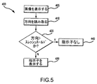
図5は、図4Cに示された歪指示子305を具現化するのに使用される動作400を示す。動作205のケースと同様に、動作400は、動作405においてユーザに画像を表示し、動作410において方向データを読み取り、そしてその方向データがスレッシュホールドより大きいかどうかを動作420において決定することにより行われる。歪が意図的なものでなく、即ち傾斜がスレッシュホールド未満であることを方向データが指示する場合には、プロセッサ130は、動作430において、歪指示子305を表示する。ある実施形態では、これは、スイッチ125を押して、ユーザがディスプレイ170に画像の写真を撮影したいことを指示する結果として生じ(動作405の間に)、それ故、ユーザは、動作430の間に画像捕獲装置100を傾斜させてディスプレイ170に示された歪指示子305に画像を整列させることにより画像を手動で修正する機会を得る。方向がスレッシュホールドより大きい(例えば、傾斜が故意である)ことを動作420が指示する場合には、動作430においてディスプレイ170から歪指示子305が除去される。
FIG. 5 shows an operation 400 used to implement the
X、Y及び/又はZ軸の画像歪を修正するのに加えて、加速度計150により測定された方向データを距離データに関連して使用して、物体160の画像に存在する遠近歪を修正することができる。「遠近歪」という語は、一般的に、画像センサ120及び物体160が互いにある角度にあることから生じる物体160の歪曲を指す。図6は、図1に示す画像捕獲装置100を動作するときの潜在的な遠近歪を示す。図7を参照すれば、物体160は、地面及び/又は水平に対して実質的に非垂直位置にあり、θ1で示されている。この相対的な非垂直位置の結果として、画像センサ120に提示される画像は、歪曲又はスキューされ、この画像の写真は、遠近歪を有する。例えば、図7Aは、ディスプレイ170に表示される、遠近歪を含むビッグベンの画像を示す。
In addition to correcting image distortions in the X, Y and / or Z axes, the direction data measured by the
ある実施形態では、距離測定センサ155は、遠近歪を修正するために加速度計150からの方向データに関連して使用される1つ以上の距離測定値を与える。例えば、ある実施形態では、距離測定センサ155は、画像センサ120と物体160との間に延びて画像センサ120に直交するベクトルの距離d1を測定する。更に、距離測定センサ155は、画像センサ120と物体160との間に延びて地面に平行なベクトルの距離d2を測定する。更に、加速度計150は、地面に対する画像センサ120の角度θ2を測定する。距離測定値d1及びd2並びに角度θ2に基づき、水平に対する物体160の角度θ1を三角法の動作で決定することができる。プロセッサ130で角度θ1を計算することにより、画像データをメモリ165に記憶する前に遠近変換動作を使用して遠近歪をオンザフライで修正することができる。上述したように、そのようなオンザフライの修正は、メモリ165のスペースを保存する。図7Bは、遠近歪変換で処理された図7Aの画像を示す。他の実施形態では、距離測定値d1及びd2並びに角度θ2が画像データのヘッダに記憶され、角度θ1を後で計算することにより遠近変換が適用される。
In some embodiments, the
図7A及び7Bを比較することから明らかなように、遠近歪を修正するときに元の画像の縦横比を保存するために、図7Aから画像データの一部分が切り落とされる。同様に、図4A及び4Bを比較することから明らかなように、傾斜歪を修正するときにも画像データの一部分が切り落とされる。傾斜歪又は遠近歪を修正するときに画像から画像データを切り落とすので、ある実施形態では、動的な切り落とし線を使用して切り落とすべき部分がディスプレイ170においてユーザに指示される。図7Cは、図7Aに示す画像に課せられた動的な切り落とし線505を示す。動的な切り落とし線310は、傾斜及び/又は遠近歪修正の後にユーザが望む細部が保存されるように、写真撮影されるべき物体をフレーミングする上でユーザの助けとなる。
As is apparent from comparing FIGS. 7A and 7B, a portion of the image data is cut off from FIG. 7A to preserve the aspect ratio of the original image when correcting perspective distortion. Similarly, as is apparent from comparing FIGS. 4A and 4B, a portion of the image data is also cut off when correcting the tilt distortion. Because image data is clipped from the image when correcting tilt or perspective distortion, in one embodiment, a dynamic cut line is used to indicate to the user on the
100:画像捕獲装置
110:アパーチャー
120:画像センサ
121:レンズ
125:スイッチ
130:プロセッサ
150:加速度計
155:距離センサ
160:写真撮影される物体
165:メモリ
170:ディスプレイスクリーン
190:可聴警報装置
100: Image capture device 110: Aperture 120: Image sensor 121: Lens 125: Switch 130: Processor 150: Accelerometer 155: Distance sensor 160: Object to be photographed 165: Memory 170: Display screen 190: Audible alarm device
Claims (19)
画像データを含む画像の捕獲中に、画像捕獲装置の方向測定値を読み取る段階と、
前記画像における一つ以上のまっすぐな縁の方向を決定する段階と、
差の指標を決定する段階と、
前記差の指標がスレッシュホールド未満である場合に、前記画像データを修正することにより、前記画像を修正する段階と、
を備え、前記差の指標は、前記一つ以上のまっすぐな縁の一つが前記画像捕獲装置の前記方向測定値だけ方向が調整された後に、前記一つ以上のまっすぐな縁の一つが垂直にどれほど近接しているかの程度に等しい、方法。 In a method for compensating for image distortion,
During the capture of an image containing image data, reading the orientation measurement of the image capture device;
Determining the direction of one or more straight edges in the image;
Determining a measure of difference;
Modifying the image by modifying the image data if the difference indicator is less than a threshold; and
And wherein the one or more straight edges are vertically aligned after the one or more straight edges are adjusted in direction by the direction measurement of the image capture device. A method equal to how close they are .
撮影画像を表すデータから成る画像の捕獲動作中に、画像捕獲装置の方向測定値を得させ、
前記撮影画像中のまっすぐな縁に対応する前記データ内の一つ以上のまっすぐな縁を識別させ、
前記一つ以上のまっすぐな縁の一つが前記画像捕獲装置の前記方向測定値だけ方向が調整された後に、前記一つ以上のまっすぐな縁の一つが垂直にどれほど近接しているかの程度に等しい差の指標を決定させ、
前記差の指標がスレッシュホールド未満である場合に、前記データを修正させる命令を含む、
プロセッサ読み取り可能な非一時的記憶装置。 A processor-readable non-transitory storage device, wherein instructions stored in the storage device are transmitted to one or more processors,
During the capture operation of the image consisting of data representing the captured image, the direction measurement value of the image capture device is obtained,
Identifying one or more straight edges in the data corresponding to straight edges in the captured image;
One of the one or more straight edges is equal to how close one of the one or more straight edges is vertically after the direction is adjusted by the direction measurement of the image capture device Let me determine the indicator of the difference ,
Including instructions to modify the data if the difference indicator is less than a threshold;
A processor-readable non-transitory storage device.
一つ以上のまっすぐな縁の第1のまっすぐな縁の方向と前記一つ以上の軸の第1の軸に沿った前記方向測定値との間の第1の角度差を決定させ、
一つ以上のまっすぐな縁の前記第1のまっすぐな縁の方向と前記一つ以上の軸の第2の軸に沿った前記方向測定値との間の第2の角度差を決定させる命令を含む、請求項10に記載の非一時的記憶装置。 An instruction that causes the one or more processors to determine an index of difference is provided to the one or more processors,
Determining a first angular difference between a direction of a first straight edge of one or more straight edges and the directional measurement along a first axis of the one or more axes;
Instructions to determine a second angular difference between the direction of the first straight edge of one or more straight edges and the direction measurement along a second axis of the one or more axes; The non-transitory storage device according to claim 10, comprising:
前記第1のまっすぐな縁の前記方向が、前記第1の角度差に少なくとも部分的に基づいて、前記第1の軸に沿った前記測定方向に一致するように前記データを修正させ、且つ
前記第1のまっすぐな縁の前記方向が、前記第2の角度差に少なくとも部分的に基づいて、前記第2の軸に沿った前記方向測定値に一致するように前記データを修正させる命令を含む、請求項15に記載の非一時的記憶装置。 An instruction that causes the one or more processors to modify the data is provided to the one or more processors,
Modifying the data such that the direction of the first straight edge coincides with the measurement direction along the first axis based at least in part on the first angular difference; and Instructions for modifying the data such that the direction of the first straight edge matches the direction measurement along the second axis based at least in part on the second angular difference; The non-transitory storage device according to claim 15.
Applications Claiming Priority (3)
| Application Number | Priority Date | Filing Date | Title |
|---|---|---|---|
| US12/644,800 US8687070B2 (en) | 2009-12-22 | 2009-12-22 | Image capture device having tilt and/or perspective correction |
| US12/644,800 | 2009-12-22 | ||
| PCT/US2010/054667 WO2011078913A1 (en) | 2009-12-22 | 2010-10-29 | Image capture device having tilt or perspective correction |
Publications (3)
| Publication Number | Publication Date |
|---|---|
| JP2013515432A JP2013515432A (en) | 2013-05-02 |
| JP2013515432A5 JP2013515432A5 (en) | 2014-11-06 |
| JP5670476B2 true JP5670476B2 (en) | 2015-02-18 |
Family
ID=43466768
Family Applications (1)
| Application Number | Title | Priority Date | Filing Date |
|---|---|---|---|
| JP2012545944A Active JP5670476B2 (en) | 2009-12-22 | 2010-10-29 | Image capture device with tilt or perspective correction capability |
Country Status (11)
| Country | Link |
|---|---|
| US (3) | US8687070B2 (en) |
| EP (1) | EP2517455A1 (en) |
| JP (1) | JP5670476B2 (en) |
| KR (3) | KR20120106858A (en) |
| CN (2) | CN104717429B (en) |
| AU (2) | AU2010333908B2 (en) |
| BR (1) | BR112012017772A2 (en) |
| HK (1) | HK1175053A1 (en) |
| MX (1) | MX2012007345A (en) |
| TW (2) | TWI471002B (en) |
| WO (1) | WO2011078913A1 (en) |
Families Citing this family (112)
| Publication number | Priority date | Publication date | Assignee | Title |
|---|---|---|---|---|
| CN104270571B (en) * | 2014-10-20 | 2018-06-01 | 联想(北京)有限公司 | Image processing method and electronic equipment |
| EP1768387B1 (en) * | 2005-09-22 | 2014-11-05 | Samsung Electronics Co., Ltd. | Image capturing apparatus with image compensation and method therefor |
| US8405727B2 (en) * | 2008-05-01 | 2013-03-26 | Apple Inc. | Apparatus and method for calibrating image capture devices |
| US8538084B2 (en) * | 2008-09-08 | 2013-09-17 | Apple Inc. | Method and apparatus for depth sensing keystoning |
| US8508671B2 (en) | 2008-09-08 | 2013-08-13 | Apple Inc. | Projection systems and methods |
| US7881603B2 (en) * | 2008-09-26 | 2011-02-01 | Apple Inc. | Dichroic aperture for electronic imaging device |
| US8527908B2 (en) | 2008-09-26 | 2013-09-03 | Apple Inc. | Computer user interface system and methods |
| US8610726B2 (en) * | 2008-09-26 | 2013-12-17 | Apple Inc. | Computer systems and methods with projected display |
| US20100079653A1 (en) * | 2008-09-26 | 2010-04-01 | Apple Inc. | Portable computing system with a secondary image output |
| US20100079426A1 (en) * | 2008-09-26 | 2010-04-01 | Apple Inc. | Spatial ambient light profiling |
| WO2010123011A1 (en) * | 2009-04-20 | 2010-10-28 | 京セラ株式会社 | Image capturing device and image capturing method |
| US8502926B2 (en) * | 2009-09-30 | 2013-08-06 | Apple Inc. | Display system having coherent and incoherent light sources |
| US8619128B2 (en) | 2009-09-30 | 2013-12-31 | Apple Inc. | Systems and methods for an imaging system using multiple image sensors |
| US8687070B2 (en) | 2009-12-22 | 2014-04-01 | Apple Inc. | Image capture device having tilt and/or perspective correction |
| US9124804B2 (en) * | 2010-03-22 | 2015-09-01 | Microsoft Technology Licensing, Llc | Using accelerometer information for determining orientation of pictures and video images |
| JP5136671B2 (en) * | 2010-05-13 | 2013-02-06 | 株式会社デンソー | Map display device |
| US8497897B2 (en) | 2010-08-17 | 2013-07-30 | Apple Inc. | Image capture using luminance and chrominance sensors |
| US8350919B2 (en) * | 2010-09-09 | 2013-01-08 | Vizio, Inc. | Configuration of a device based upon orientation |
| US20120069208A1 (en) * | 2010-09-19 | 2012-03-22 | Weinman Jr Joseph Bernard | Methods, Systems , and Computer Program Products for Assuring Horizontal Image Capture |
| US8538132B2 (en) | 2010-09-24 | 2013-09-17 | Apple Inc. | Component concentricity |
| CN102739928A (en) * | 2011-04-08 | 2012-10-17 | 富泰华工业(深圳)有限公司 | Camera equipment |
| CN103563352A (en) * | 2011-06-10 | 2014-02-05 | 国际商业机器公司 | Adapted digital device and adapter for digital device |
| US11039109B2 (en) * | 2011-08-05 | 2021-06-15 | Fox Sports Productions, Llc | System and method for adjusting an image for a vehicle mounted camera |
| US10939140B2 (en) | 2011-08-05 | 2021-03-02 | Fox Sports Productions, Llc | Selective capture and presentation of native image portions |
| GB201117143D0 (en) | 2011-10-05 | 2011-11-16 | Nctech Ltd | Camera |
| ITMO20110279A1 (en) * | 2011-11-04 | 2013-05-05 | Datalogic Automation Srl | METHOD OF ACQUISITION OF IMAGES |
| ITMO20110280A1 (en) * | 2011-11-04 | 2013-05-05 | Datalogic Automation Srl | METHOD OF ACQUISITION OF IMAGES |
| US9420205B2 (en) | 2011-11-04 | 2016-08-16 | Datalogic Ip Tech S.R.L. | Image acquisition method of object on supporting surface |
| KR101795603B1 (en) * | 2011-11-17 | 2017-12-01 | 삼성전자주식회사 | Digital photographing apparatus and controlling method thereof |
| US9723223B1 (en) | 2011-12-02 | 2017-08-01 | Amazon Technologies, Inc. | Apparatus and method for panoramic video hosting with directional audio |
| US9516225B2 (en) | 2011-12-02 | 2016-12-06 | Amazon Technologies, Inc. | Apparatus and method for panoramic video hosting |
| US9838687B1 (en) | 2011-12-02 | 2017-12-05 | Amazon Technologies, Inc. | Apparatus and method for panoramic video hosting with reduced bandwidth streaming |
| US8988578B2 (en) | 2012-02-03 | 2015-03-24 | Honeywell International Inc. | Mobile computing device with improved image preview functionality |
| US9134807B2 (en) * | 2012-03-02 | 2015-09-15 | Microsoft Technology Licensing, Llc | Pressure sensitive key normalization |
| US9075566B2 (en) | 2012-03-02 | 2015-07-07 | Microsoft Technoogy Licensing, LLC | Flexible hinge spine |
| US9706089B2 (en) | 2012-03-02 | 2017-07-11 | Microsoft Technology Licensing, Llc | Shifted lens camera for mobile computing devices |
| US9870066B2 (en) | 2012-03-02 | 2018-01-16 | Microsoft Technology Licensing, Llc | Method of manufacturing an input device |
| US20130300590A1 (en) | 2012-05-14 | 2013-11-14 | Paul Henry Dietz | Audio Feedback |
| US10031556B2 (en) | 2012-06-08 | 2018-07-24 | Microsoft Technology Licensing, Llc | User experience adaptation |
| JP5925059B2 (en) * | 2012-06-12 | 2016-05-25 | キヤノン株式会社 | Imaging control apparatus, imaging control method, and program |
| US20140063220A1 (en) | 2012-08-29 | 2014-03-06 | Ossur Hf | Method and Device for Ordering a Custom Orthopedic Device |
| JP2014050039A (en) * | 2012-09-03 | 2014-03-17 | Sony Corp | Image processor, image processing method and computer program |
| US9279983B1 (en) * | 2012-10-30 | 2016-03-08 | Google Inc. | Image cropping |
| US9516229B2 (en) | 2012-11-27 | 2016-12-06 | Qualcomm Incorporated | System and method for adjusting orientation of captured video |
| CN103873835A (en) * | 2012-12-17 | 2014-06-18 | 联想(北京)有限公司 | Image collecting method, image processing method and electronic device |
| US20140211031A1 (en) * | 2013-01-30 | 2014-07-31 | Microsoft Corporation | Auto picture alignment correction |
| US9330471B2 (en) * | 2013-02-14 | 2016-05-03 | Qualcomm Incorporated | Camera aided motion direction and speed estimation |
| US9282244B2 (en) | 2013-03-14 | 2016-03-08 | Microsoft Technology Licensing, Llc | Camera non-touch switch |
| EP3828496A1 (en) * | 2013-04-08 | 2021-06-02 | SNAP Inc. | Distance estimation using multi-camera device |
| US8979398B2 (en) | 2013-04-16 | 2015-03-17 | Microsoft Technology Licensing, Llc | Wearable camera |
| US9066007B2 (en) | 2013-04-26 | 2015-06-23 | Skype | Camera tap switch |
| US20150002688A1 (en) * | 2013-06-26 | 2015-01-01 | James A. Baldwin | Automated camera adjustment |
| US9609262B2 (en) * | 2013-06-27 | 2017-03-28 | Intel Corporation | Device for adaptive projection |
| WO2014205757A1 (en) * | 2013-06-28 | 2014-12-31 | Google Inc. | Systems and methods for generating accurate sensor corrections based on video input |
| US9177362B2 (en) * | 2013-08-02 | 2015-11-03 | Facebook, Inc. | Systems and methods for transforming an image |
| US9356061B2 (en) | 2013-08-05 | 2016-05-31 | Apple Inc. | Image sensor with buried light shield and vertical gate |
| ITTO20130683A1 (en) | 2013-08-08 | 2015-02-09 | Sisvel Technology Srl | APPARATUS AND METHOD FOR THE CORRECTION OF PROSPECTIVE DEFORMATIONS OF IMAGES |
| CN104427234A (en) * | 2013-09-02 | 2015-03-18 | 联想(北京)有限公司 | Image distortion correction method and electronic device |
| US9547173B2 (en) * | 2013-10-03 | 2017-01-17 | Honda Motor Co., Ltd. | System and method for dynamic in-vehicle virtual reality |
| US9630631B2 (en) | 2013-10-03 | 2017-04-25 | Honda Motor Co., Ltd. | System and method for dynamic in-vehicle virtual reality |
| US9536353B2 (en) | 2013-10-03 | 2017-01-03 | Honda Motor Co., Ltd. | System and method for dynamic in-vehicle virtual reality |
| US9715764B2 (en) * | 2013-10-03 | 2017-07-25 | Honda Motor Co., Ltd. | System and method for dynamic in-vehicle virtual reality |
| US9781356B1 (en) | 2013-12-16 | 2017-10-03 | Amazon Technologies, Inc. | Panoramic video viewer |
| CN104811602A (en) * | 2014-01-24 | 2015-07-29 | 维科技术有限公司 | Self-shooting method and self-shooting device for mobile terminals |
| JP6264173B2 (en) | 2014-04-18 | 2018-01-24 | 富士通株式会社 | Normality determination method for imaging direction, imaging device attachment state evaluation program, and imaging device attachment state evaluation device |
| JP6299371B2 (en) * | 2014-04-18 | 2018-03-28 | 富士通株式会社 | Imaging direction inclination detection method, imaging direction inclination detection program, and imaging direction inclination detection apparatus |
| JP6299373B2 (en) | 2014-04-18 | 2018-03-28 | 富士通株式会社 | Imaging direction normality determination method, imaging direction normality determination program, and imaging direction normality determination apparatus |
| US9998661B1 (en) | 2014-05-13 | 2018-06-12 | Amazon Technologies, Inc. | Panoramic camera enclosure |
| CN103997519A (en) * | 2014-05-14 | 2014-08-20 | 小米科技有限责任公司 | Method and device for transmitting image |
| US9503644B2 (en) | 2014-05-22 | 2016-11-22 | Microsoft Technology Licensing, Llc | Using image properties for processing and editing of multiple resolution images |
| US9451178B2 (en) | 2014-05-22 | 2016-09-20 | Microsoft Technology Licensing, Llc | Automatic insertion of video into a photo story |
| US11184580B2 (en) | 2014-05-22 | 2021-11-23 | Microsoft Technology Licensing, Llc | Automatically curating video to fit display time |
| US10002413B2 (en) | 2014-07-22 | 2018-06-19 | Hewlett-Packard Development Company, L.P. | Recovering planar projections |
| US9823352B2 (en) * | 2014-10-31 | 2017-11-21 | Rockwell Automation Safety Ag | Absolute distance measurement for time-of-flight sensors |
| US11159854B2 (en) | 2014-12-13 | 2021-10-26 | Fox Sports Productions, Llc | Systems and methods for tracking and tagging objects within a broadcast |
| US11758238B2 (en) | 2014-12-13 | 2023-09-12 | Fox Sports Productions, Llc | Systems and methods for displaying wind characteristics and effects within a broadcast |
| GB2539387B (en) * | 2015-06-09 | 2021-04-14 | Oxford Metrics Plc | Motion capture system |
| EP3316952A4 (en) | 2015-06-30 | 2019-03-13 | ResMed Limited | Mask sizing tool using a mobile application |
| CN105141834A (en) * | 2015-07-27 | 2015-12-09 | 努比亚技术有限公司 | Device and method for controlling picture shooting |
| CN105163034B (en) * | 2015-09-28 | 2018-06-29 | 广东欧珀移动通信有限公司 | A kind of photographic method and mobile terminal |
| US10104282B2 (en) * | 2015-09-30 | 2018-10-16 | Ricoh Co., Ltd. | Yaw user interface |
| US10220172B2 (en) | 2015-11-25 | 2019-03-05 | Resmed Limited | Methods and systems for providing interface components for respiratory therapy |
| US10184797B2 (en) * | 2015-12-18 | 2019-01-22 | Invensense, Inc. | Apparatus and methods for ultrasonic sensor navigation |
| CN105704374B (en) * | 2016-01-29 | 2019-04-05 | 努比亚技术有限公司 | A kind of image conversion apparatus, method and terminal |
| US10362969B2 (en) * | 2016-05-04 | 2019-07-30 | Sensors Unlimited, Inc. | Image-based detection and diagnosis of diastasis recti |
| WO2018005730A1 (en) * | 2016-06-29 | 2018-01-04 | Vision Quest Industries Incorporated Dba Vq Orthocare | Measurement and ordering system for orthotic devices |
| KR102500715B1 (en) | 2016-07-28 | 2023-02-17 | 삼성전자주식회사 | Electronic apparatus and controlling method thereof |
| TWI599236B (en) * | 2016-08-19 | 2017-09-11 | 山衛科技股份有限公司 | Instrument test system, instrument test method, and computer program product thereof |
| JP6766715B2 (en) * | 2017-03-22 | 2020-10-14 | トヨタ自動車株式会社 | Display control device for vehicles |
| US11085611B2 (en) * | 2017-06-15 | 2021-08-10 | Board Of Supervisors Of Louisiana State University And Agricultural And Mechanical College | Tracking lighting system |
| CN107702714B (en) * | 2017-07-31 | 2020-01-07 | 广州维绅科技有限公司 | Positioning method, device and system |
| CN107607204A (en) * | 2017-09-05 | 2018-01-19 | 昆山博威泰克电子科技有限公司 | Color analysis device and method |
| US10705673B2 (en) * | 2017-09-30 | 2020-07-07 | Intel Corporation | Posture and interaction incidence for input and output determination in ambient computing |
| US11941847B2 (en) | 2018-03-19 | 2024-03-26 | Jaguar Land Rover Limited | Controller for a vehicle |
| GB2572143B (en) * | 2018-03-19 | 2020-07-08 | Jaguar Land Rover Ltd | Controller for a vehicle |
| US11048745B2 (en) * | 2018-06-22 | 2021-06-29 | International Business Machines Corporation | Cognitively identifying favorable photograph qualities |
| US10972656B2 (en) | 2018-06-22 | 2021-04-06 | International Business Machines Corporation | Cognitively coaching a subject of a photograph |
| US10970576B2 (en) * | 2018-08-27 | 2021-04-06 | Daon Holdings Limited | Methods and systems for capturing image data |
| CN110086982A (en) * | 2019-03-12 | 2019-08-02 | 浙江艺旗教育科技有限公司 | A kind of perspective image antidote and device |
| WO2020205502A1 (en) * | 2019-03-29 | 2020-10-08 | Popsockets Llc | Obscured media communication |
| CN110326287A (en) * | 2019-05-14 | 2019-10-11 | 深圳市大疆创新科技有限公司 | Image pickup method and device |
| US10917573B1 (en) * | 2019-05-21 | 2021-02-09 | Gopro, Inc. | Systems and methods for stabilizing videos |
| KR102209908B1 (en) * | 2019-09-16 | 2021-01-29 | 재단법인 다차원 스마트 아이티 융합시스템 연구단 | Image transform camera apparatus for implementing bellows camera in software and operation method thereof |
| US10983363B2 (en) | 2019-09-19 | 2021-04-20 | Fotonation Limited | Method for stabilizing a camera frame of a video sequence |
| US11435811B2 (en) * | 2019-12-09 | 2022-09-06 | Micron Technology, Inc. | Memory device sensors |
| US11228702B1 (en) | 2021-04-23 | 2022-01-18 | Gopro, Inc. | Stabilization of face in video |
| US11663704B2 (en) | 2021-04-28 | 2023-05-30 | Microsoft Technology Licensing, Llc | Distortion correction via modified analytical projection |
| US11822713B2 (en) * | 2021-06-11 | 2023-11-21 | Rockwell Collins, Inc. | Pose augmentation of head worn display video for latency reduction |
| WO2023282963A1 (en) * | 2021-07-06 | 2023-01-12 | Qualcomm Incorporated | Enhanced object detection |
| US11792505B2 (en) * | 2021-07-06 | 2023-10-17 | Qualcomm Incorporated | Enhanced object detection |
| US11706527B1 (en) * | 2022-04-06 | 2023-07-18 | Gopro, Inc. | Systems and methods for stabilizing videos |
| WO2023229270A1 (en) * | 2022-05-27 | 2023-11-30 | Samsung Electronics Co., Ltd. | Method and electronic device for tilt correction of video |
Family Cites Families (116)
| Publication number | Priority date | Publication date | Assignee | Title |
|---|---|---|---|---|
| US3363104A (en) * | 1965-10-01 | 1968-01-09 | North American Aviation Inc | Detection system for coherent light beams |
| GB1356730A (en) * | 1971-09-09 | 1974-06-12 | Wandel & Goltermann | System for the documentary recording with x-y-recorder |
| US4620222A (en) * | 1982-11-10 | 1986-10-28 | Matsushita Electric Industrial Co., Ltd. | Digital color TV camera |
| JPS612490A (en) | 1984-06-14 | 1986-01-08 | Sony Corp | Recorder |
| US5272473A (en) * | 1989-02-27 | 1993-12-21 | Texas Instruments Incorporated | Reduced-speckle display system |
| US5274494A (en) * | 1991-04-25 | 1993-12-28 | Hughes Aircraft Company | Speckle suppression illuminator |
| GB9125954D0 (en) | 1991-12-06 | 1992-02-05 | Vlsi Vision Ltd | Electronic camera |
| JPH05164687A (en) * | 1991-12-18 | 1993-06-29 | Hamamatsu Photonics Kk | Ratio imaging apparatus |
| US5757423A (en) * | 1993-10-22 | 1998-05-26 | Canon Kabushiki Kaisha | Image taking apparatus |
| JPH089309A (en) * | 1994-06-23 | 1996-01-12 | Canon Inc | Display method and its device |
| JPH11102438A (en) * | 1997-09-26 | 1999-04-13 | Minolta Co Ltd | Distance image generation device and image display device |
| US6560711B1 (en) * | 1999-05-24 | 2003-05-06 | Paul Given | Activity sensing interface between a computer and an input peripheral |
| US6282655B1 (en) * | 1999-05-24 | 2001-08-28 | Paul Given | Keyboard motion detector |
| US6339429B1 (en) * | 1999-06-04 | 2002-01-15 | Mzmz Technology Innovations Llc | Dynamic art form display apparatus |
| JP3509652B2 (en) * | 1999-08-23 | 2004-03-22 | 日本電気株式会社 | Projector device |
| US7028269B1 (en) * | 2000-01-20 | 2006-04-11 | Koninklijke Philips Electronics N.V. | Multi-modal video target acquisition and re-direction system and method |
| GB2359895B (en) * | 2000-03-03 | 2003-09-10 | Hewlett Packard Co | Camera projected viewfinder |
| US7213254B2 (en) * | 2000-04-07 | 2007-05-01 | Koplar Interactive Systems International Llc | Universal methods and device for hand-held promotional opportunities |
| US7554578B2 (en) * | 2000-07-11 | 2009-06-30 | Phase One A/S | Digital camera with integrated accelerometers |
| US6924909B2 (en) * | 2001-02-20 | 2005-08-02 | Eastman Kodak Company | High-speed scanner having image processing for improving the color reproduction and visual appearance thereof |
| JP3640173B2 (en) * | 2001-04-02 | 2005-04-20 | ソニー株式会社 | Image display device |
| JP2002354493A (en) | 2001-05-25 | 2002-12-06 | Canon Inc | Multi-lens and multi-ccd type image pickup device |
| US7259747B2 (en) * | 2001-06-05 | 2007-08-21 | Reactrix Systems, Inc. | Interactive video display system |
| AU2002312676A1 (en) * | 2001-06-12 | 2002-12-23 | Silicon Optix Inc. | System and method for correcting keystone distortion |
| US7079707B2 (en) * | 2001-07-20 | 2006-07-18 | Hewlett-Packard Development Company, L.P. | System and method for horizon correction within images |
| US6862022B2 (en) * | 2001-07-20 | 2005-03-01 | Hewlett-Packard Development Company, L.P. | Method and system for automatically selecting a vertical refresh rate for a video display monitor |
| US20030038927A1 (en) * | 2001-08-27 | 2003-02-27 | Alden Ray M. | Image projector with integrated image stabilization for handheld devices and portable hardware |
| US6636292B2 (en) * | 2001-09-05 | 2003-10-21 | Eastman Kodak Company | Printing apparatus for photosensitive media having a hybrid light source |
| US6870684B2 (en) * | 2001-09-24 | 2005-03-22 | Kulicke & Soffa Investments, Inc. | Multi-wavelength aperture and vision system and method using same |
| JP2003143459A (en) * | 2001-11-02 | 2003-05-16 | Canon Inc | Compound-eye image pickup system and device provided therewith |
| US20030117343A1 (en) * | 2001-12-14 | 2003-06-26 | Kling Ralph M. | Mobile computer with an integrated micro projection display |
| US7460179B2 (en) * | 2002-01-31 | 2008-12-02 | Hewlett-Packard Development Company, L.P. | Adaptive image display |
| US6930669B2 (en) * | 2002-03-18 | 2005-08-16 | Technology Innovations, Llc | Portable personal computing device with fully integrated projection display system |
| US6931601B2 (en) * | 2002-04-03 | 2005-08-16 | Microsoft Corporation | Noisy operating system user interface |
| GB0208654D0 (en) * | 2002-04-16 | 2002-05-29 | Koninkl Philips Electronics Nv | Image processing for video or photographic equipment |
| US6877863B2 (en) * | 2002-06-12 | 2005-04-12 | Silicon Optix Inc. | Automatic keystone correction system and method |
| US20050132408A1 (en) * | 2003-05-30 | 2005-06-16 | Andrew Dahley | System for controlling a video display |
| WO2004025466A2 (en) | 2002-09-16 | 2004-03-25 | Clearcube Technology, Inc. | Distributed computing infrastructure |
| US7058234B2 (en) * | 2002-10-25 | 2006-06-06 | Eastman Kodak Company | Enhancing the tonal, spatial, and color characteristics of digital images using expansive and compressive tone scale functions |
| US6807010B2 (en) * | 2002-11-13 | 2004-10-19 | Eastman Kodak Company | Projection display apparatus having both incoherent and laser light sources |
| US8745541B2 (en) * | 2003-03-25 | 2014-06-03 | Microsoft Corporation | Architecture for controlling a computer using hand gestures |
| JP2004343476A (en) | 2003-05-16 | 2004-12-02 | Sony Corp | Image pickup device, processor of image pickup result, and method for processing same result |
| US6921172B2 (en) * | 2003-07-02 | 2005-07-26 | Hewlett-Packard Development Company, L.P. | System and method for increasing projector amplitude resolution and correcting luminance non-uniformity |
| AU2004262451B2 (en) * | 2003-08-12 | 2009-11-26 | Tigenix N.V. | Use of CXCL6 chemokine in the prevention or repair of cartilage defects |
| JP4036168B2 (en) * | 2003-09-09 | 2008-01-23 | 株式会社日立製作所 | mobile phone |
| JP4363151B2 (en) * | 2003-10-14 | 2009-11-11 | カシオ計算機株式会社 | Imaging apparatus, image processing method thereof, and program |
| US7453510B2 (en) * | 2003-12-11 | 2008-11-18 | Nokia Corporation | Imaging device |
| US7123298B2 (en) * | 2003-12-18 | 2006-10-17 | Avago Technologies Sensor Ip Pte. Ltd. | Color image sensor with imaging elements imaging on respective regions of sensor elements |
| US6970080B1 (en) * | 2003-12-31 | 2005-11-29 | Crouch Shawn D | Computer shut down system |
| US20050182962A1 (en) * | 2004-02-17 | 2005-08-18 | Paul Given | Computer security peripheral |
| US20070177279A1 (en) * | 2004-02-27 | 2007-08-02 | Ct Electronics Co., Ltd. | Mini camera device for telecommunication devices |
| JP2005267457A (en) * | 2004-03-19 | 2005-09-29 | Casio Comput Co Ltd | Image processing device, imaging apparatus, image processing method and program |
| US20050280786A1 (en) * | 2004-06-22 | 2005-12-22 | Jean-Paul Moiroux | Integrated computer and projector system |
| TWI244861B (en) * | 2004-07-06 | 2005-12-01 | Asia Optical Co Inc | Device and method for optical center detection |
| US20060033819A1 (en) * | 2004-08-12 | 2006-02-16 | Sony Corporation | Method and apparatus for automatic orientation correction of digital photographs |
| JP2006115346A (en) | 2004-10-15 | 2006-04-27 | Olympus Corp | Imaging apparatus and camera shake correction method |
| JP4396500B2 (en) | 2004-12-07 | 2010-01-13 | カシオ計算機株式会社 | Imaging apparatus, image orientation adjustment method, and program |
| EP1672460B1 (en) * | 2004-12-15 | 2009-11-25 | STMicroelectronics (Research & Development) Limited | Computer user detection apparatus |
| JP4196942B2 (en) * | 2004-12-21 | 2008-12-17 | セイコーエプソン株式会社 | IMAGING DEVICE AND MOBILE PHONE HAVING THE SAME |
| JP4753065B2 (en) * | 2005-02-04 | 2011-08-17 | 富士フイルム株式会社 | Image blur correction device |
| US7653304B2 (en) * | 2005-02-08 | 2010-01-26 | Nikon Corporation | Digital camera with projector and digital camera system |
| US7512262B2 (en) * | 2005-02-25 | 2009-03-31 | Microsoft Corporation | Stereo-based image processing |
| JP2006245726A (en) * | 2005-03-01 | 2006-09-14 | Fuji Photo Film Co Ltd | Digital camera |
| JP4379363B2 (en) | 2005-03-29 | 2009-12-09 | セイコーエプソン株式会社 | Image tilt correction with angle of view maintained |
| US20080191864A1 (en) * | 2005-03-31 | 2008-08-14 | Ronen Wolfson | Interactive Surface and Display System |
| US8044880B2 (en) * | 2005-04-28 | 2011-10-25 | Hitachi, Ltd. | Projection type image display device |
| US20070027580A1 (en) * | 2005-07-14 | 2007-02-01 | Ligtenberg Chris A | Thermal control of an electronic device for adapting to ambient conditions |
| US20090008683A1 (en) * | 2005-07-21 | 2009-01-08 | Matshushita Electric Industrial Co., Ltd. | Imaging apparatus |
| WO2007018085A1 (en) * | 2005-08-08 | 2007-02-15 | Konica Minolta Opto, Inc. | Imaging device and assembling method for imaging device |
| US7964835B2 (en) * | 2005-08-25 | 2011-06-21 | Protarius Filo Ag, L.L.C. | Digital cameras with direct luminance and chrominance detection |
| US7714897B2 (en) * | 2005-09-15 | 2010-05-11 | Nokia Corporation | Trigger tone of a camera |
| WO2007035720A2 (en) * | 2005-09-20 | 2007-03-29 | Deltasphere, Inc. | Methods, systems, and computer program products for acquiring three-dimensional range information |
| US7413311B2 (en) * | 2005-09-29 | 2008-08-19 | Coherent, Inc. | Speckle reduction in laser illuminated projection displays having a one-dimensional spatial light modulator |
| US7629897B2 (en) * | 2005-10-21 | 2009-12-08 | Reino Koljonen | Orally Mounted wireless transcriber device |
| WO2007056110A2 (en) * | 2005-11-02 | 2007-05-18 | Microvision, Inc. | Image projector with selectable display modes |
| US7641348B2 (en) * | 2006-01-31 | 2010-01-05 | Hewlett-Packard Development Company, L.P. | Integrated portable computer projector system |
| US7570881B2 (en) * | 2006-02-21 | 2009-08-04 | Nokia Corporation | Color balanced camera with a flash light unit |
| WO2007100057A1 (en) | 2006-03-03 | 2007-09-07 | Matsushita Electric Industrial Co., Ltd. | Imaging device and integrated circuit |
| JP2007258989A (en) * | 2006-03-22 | 2007-10-04 | Eastman Kodak Co | Digital camera, composition corrector, and composition correcting method |
| US8139059B2 (en) | 2006-03-31 | 2012-03-20 | Microsoft Corporation | Object illumination in a virtual environment |
| US20070300312A1 (en) * | 2006-06-22 | 2007-12-27 | Microsoft Corporation Microsoft Patent Group | User presence detection for altering operation of a computing system |
| US7658498B2 (en) * | 2006-07-13 | 2010-02-09 | Dell Products, Inc. | System and method for automated display orientation detection and compensation |
| US20090115915A1 (en) * | 2006-08-09 | 2009-05-07 | Fotonation Vision Limited | Camera Based Feedback Loop Calibration of a Projection Device |
| US8406562B2 (en) * | 2006-08-11 | 2013-03-26 | Geo Semiconductor Inc. | System and method for automated calibration and correction of display geometry and color |
| US7593627B2 (en) * | 2006-08-18 | 2009-09-22 | Sony Ericsson Mobile Communications Ab | Angle correction for camera |
| US7847831B2 (en) * | 2006-08-30 | 2010-12-07 | Panasonic Corporation | Image signal processing apparatus, image coding apparatus and image decoding apparatus, methods thereof, processors thereof, and, imaging processor for TV conference system |
| US7567752B2 (en) * | 2006-11-24 | 2009-07-28 | Sony Ericsson Mobile Communications Ab | Image alignment system with overlying frame in display |
| JP4406937B2 (en) * | 2006-12-01 | 2010-02-03 | 富士フイルム株式会社 | Imaging device |
| US8094195B2 (en) * | 2006-12-28 | 2012-01-10 | Flextronics International Usa, Inc. | Digital camera calibration method |
| ATE501594T1 (en) | 2007-06-27 | 2011-03-15 | Panasonic Corp | IMAGING DEVICE, METHOD, SYSTEM INTEGRATED CIRCUIT AND PROGRAM |
| EP2053844B1 (en) | 2007-06-28 | 2011-05-18 | Panasonic Corporation | Image processing device, image processing method, and program |
| US8726194B2 (en) * | 2007-07-27 | 2014-05-13 | Qualcomm Incorporated | Item selection using enhanced control |
| CN101374198A (en) * | 2007-08-24 | 2009-02-25 | 鸿富锦精密工业(深圳)有限公司 | Camera device and automatic frontal method for image thereof |
| US20090221368A1 (en) * | 2007-11-28 | 2009-09-03 | Ailive Inc., | Method and system for creating a shared game space for a networked game |
| JP2009218661A (en) | 2008-03-07 | 2009-09-24 | Panasonic Corp | Imaging device with image distortion correcting function |
| JP5129638B2 (en) * | 2008-04-02 | 2013-01-30 | ペンタックスリコーイメージング株式会社 | Imaging device |
| US20090262306A1 (en) * | 2008-04-16 | 2009-10-22 | Quinn Liam B | System and Method for Integration of a Projector and Information Handling System in a Common Chassis |
| US20090262343A1 (en) | 2008-04-18 | 2009-10-22 | Archibald William B | Infrared spectroscopy of media, including aqueous |
| US8405727B2 (en) * | 2008-05-01 | 2013-03-26 | Apple Inc. | Apparatus and method for calibrating image capture devices |
| US20090309826A1 (en) * | 2008-06-17 | 2009-12-17 | Searete Llc, A Limited Liability Corporation Of The State Of Delaware | Systems and devices |
| US8538084B2 (en) * | 2008-09-08 | 2013-09-17 | Apple Inc. | Method and apparatus for depth sensing keystoning |
| US8508671B2 (en) * | 2008-09-08 | 2013-08-13 | Apple Inc. | Projection systems and methods |
| US7869204B2 (en) * | 2008-09-15 | 2011-01-11 | International Business Machines Corporation | Compact size portable computer having a fully integrated virtual keyboard projector and a display projector |
| US20100073499A1 (en) * | 2008-09-25 | 2010-03-25 | Apple Inc. | Image capture using separate luminance and chrominance sensors |
| US8527908B2 (en) * | 2008-09-26 | 2013-09-03 | Apple Inc. | Computer user interface system and methods |
| US20100079426A1 (en) * | 2008-09-26 | 2010-04-01 | Apple Inc. | Spatial ambient light profiling |
| US8610726B2 (en) * | 2008-09-26 | 2013-12-17 | Apple Inc. | Computer systems and methods with projected display |
| US20100079653A1 (en) * | 2008-09-26 | 2010-04-01 | Apple Inc. | Portable computing system with a secondary image output |
| US7881603B2 (en) * | 2008-09-26 | 2011-02-01 | Apple Inc. | Dichroic aperture for electronic imaging device |
| US20100103172A1 (en) * | 2008-10-28 | 2010-04-29 | Apple Inc. | System and method for rendering ambient light affected appearing imagery based on sensed ambient lighting |
| US20100321482A1 (en) * | 2009-06-17 | 2010-12-23 | Lc Technologies Inc. | Eye/head controls for camera pointing |
| US8502926B2 (en) * | 2009-09-30 | 2013-08-06 | Apple Inc. | Display system having coherent and incoherent light sources |
| US8619128B2 (en) * | 2009-09-30 | 2013-12-31 | Apple Inc. | Systems and methods for an imaging system using multiple image sensors |
| US8687070B2 (en) * | 2009-12-22 | 2014-04-01 | Apple Inc. | Image capture device having tilt and/or perspective correction |
| US8497897B2 (en) * | 2010-08-17 | 2013-07-30 | Apple Inc. | Image capture using luminance and chrominance sensors |
| US8538132B2 (en) * | 2010-09-24 | 2013-09-17 | Apple Inc. | Component concentricity |
-
2009
- 2009-12-22 US US12/644,800 patent/US8687070B2/en active Active
-
2010
- 2010-10-29 CN CN201510140143.7A patent/CN104717429B/en active Active
- 2010-10-29 CN CN201080058371.5A patent/CN102668541B/en active Active
- 2010-10-29 JP JP2012545944A patent/JP5670476B2/en active Active
- 2010-10-29 WO PCT/US2010/054667 patent/WO2011078913A1/en active Application Filing
- 2010-10-29 BR BR112012017772A patent/BR112012017772A2/en not_active Application Discontinuation
- 2010-10-29 KR KR1020127019257A patent/KR20120106858A/en not_active Application Discontinuation
- 2010-10-29 EP EP10776233A patent/EP2517455A1/en not_active Ceased
- 2010-10-29 KR KR1020147030280A patent/KR101498441B1/en active IP Right Grant
- 2010-10-29 MX MX2012007345A patent/MX2012007345A/en not_active Application Discontinuation
- 2010-10-29 AU AU2010333908A patent/AU2010333908B2/en active Active
- 2010-10-29 KR KR1020147030300A patent/KR101498442B1/en active IP Right Grant
- 2010-12-07 TW TW99142670A patent/TWI471002B/en active
- 2010-12-07 TW TW103145341A patent/TWI571125B/en active
-
2013
- 2013-02-21 HK HK13102171.2A patent/HK1175053A1/en unknown
-
2014
- 2014-02-07 US US14/175,752 patent/US9113078B2/en active Active
- 2014-07-10 AU AU2014203801A patent/AU2014203801B2/en active Active
-
2015
- 2015-08-17 US US14/828,448 patent/US9565364B2/en active Active
Also Published As
| Publication number | Publication date |
|---|---|
| EP2517455A1 (en) | 2012-10-31 |
| TW201513665A (en) | 2015-04-01 |
| CN104717429B (en) | 2019-05-07 |
| HK1175053A1 (en) | 2013-06-21 |
| US20150358551A1 (en) | 2015-12-10 |
| KR101498441B1 (en) | 2015-03-03 |
| JP2013515432A (en) | 2013-05-02 |
| US20140152859A1 (en) | 2014-06-05 |
| KR20120106858A (en) | 2012-09-26 |
| US9113078B2 (en) | 2015-08-18 |
| KR20140138346A (en) | 2014-12-03 |
| AU2010333908B2 (en) | 2014-04-10 |
| AU2010333908A1 (en) | 2012-07-05 |
| US9565364B2 (en) | 2017-02-07 |
| KR20140138345A (en) | 2014-12-03 |
| US20110149094A1 (en) | 2011-06-23 |
| WO2011078913A1 (en) | 2011-06-30 |
| AU2014203801A1 (en) | 2014-07-31 |
| CN102668541B (en) | 2015-02-18 |
| MX2012007345A (en) | 2012-07-10 |
| KR101498442B1 (en) | 2015-03-03 |
| US8687070B2 (en) | 2014-04-01 |
| CN104717429A (en) | 2015-06-17 |
| TWI571125B (en) | 2017-02-11 |
| TW201143391A (en) | 2011-12-01 |
| CN102668541A (en) | 2012-09-12 |
| BR112012017772A2 (en) | 2016-04-19 |
| AU2014203801B2 (en) | 2015-07-30 |
| TWI471002B (en) | 2015-01-21 |
Similar Documents
| Publication | Publication Date | Title |
|---|---|---|
| JP5670476B2 (en) | Image capture device with tilt or perspective correction capability | |
| JP6116486B2 (en) | Dimension measurement method | |
| JP5659305B2 (en) | Image generating apparatus and image generating method | |
| US20150304652A1 (en) | Device orientation correction method for panorama images | |
| US20080152199A1 (en) | Image orientation for display | |
| JP6942940B2 (en) | Image processing equipment, image processing methods and programs | |
| JP2010502045A (en) | Camera angle correction | |
| TW201617717A (en) | Method and system for stabilization and reframing | |
| JPWO2013069047A1 (en) | Image generating apparatus and image generating method | |
| JPWO2013069048A1 (en) | Image generating apparatus and image generating method | |
| JP5547356B2 (en) | Imaging apparatus, method, storage medium, and program | |
| TW201536050A (en) | Image-capturing method for correcting deviation-viewing angle, its computer program product, and image-capturing device for correcting deviation viewing angle | |
| EP4068749A1 (en) | Electronic terminal, photographing method and device, and storage medium | |
| JP5954987B2 (en) | Imaging apparatus and processing method thereof | |
| KR20140132452A (en) | electro device for correcting image and method for controlling thereof | |
| KR20150027555A (en) | Apparatus and method of perspective distortion correction of an image for optical character recognition | |
| JP2016208275A (en) | Image capturing apparatus and control method of the same | |
| JP2014216744A (en) | Imaging device |
Legal Events
| Date | Code | Title | Description |
|---|---|---|---|
| A977 | Report on retrieval |
Free format text: JAPANESE INTERMEDIATE CODE: A971007 Effective date: 20130724 |
|
| A131 | Notification of reasons for refusal |
Free format text: JAPANESE INTERMEDIATE CODE: A131 Effective date: 20130731 |
|
| A521 | Request for written amendment filed |
Free format text: JAPANESE INTERMEDIATE CODE: A523 Effective date: 20131030 |
|
| A131 | Notification of reasons for refusal |
Free format text: JAPANESE INTERMEDIATE CODE: A131 Effective date: 20131202 |
|
| A521 | Request for written amendment filed |
Free format text: JAPANESE INTERMEDIATE CODE: A523 Effective date: 20140224 |
|
| A02 | Decision of refusal |
Free format text: JAPANESE INTERMEDIATE CODE: A02 Effective date: 20140507 |
|
| A521 | Request for written amendment filed |
Free format text: JAPANESE INTERMEDIATE CODE: A523 Effective date: 20140908 |
|
| A524 | Written submission of copy of amendment under article 19 pct |
Free format text: JAPANESE INTERMEDIATE CODE: A524 Effective date: 20140908 |
|
| A911 | Transfer to examiner for re-examination before appeal (zenchi) |
Free format text: JAPANESE INTERMEDIATE CODE: A911 Effective date: 20140917 |
|
| TRDD | Decision of grant or rejection written | ||
| A01 | Written decision to grant a patent or to grant a registration (utility model) |
Free format text: JAPANESE INTERMEDIATE CODE: A01 Effective date: 20141117 |
|
| A61 | First payment of annual fees (during grant procedure) |
Free format text: JAPANESE INTERMEDIATE CODE: A61 Effective date: 20141217 |
|
| R150 | Certificate of patent or registration of utility model |
Ref document number: 5670476 Country of ref document: JP Free format text: JAPANESE INTERMEDIATE CODE: R150 |
|
| R250 | Receipt of annual fees |
Free format text: JAPANESE INTERMEDIATE CODE: R250 |
|
| R250 | Receipt of annual fees |
Free format text: JAPANESE INTERMEDIATE CODE: R250 |
|
| R250 | Receipt of annual fees |
Free format text: JAPANESE INTERMEDIATE CODE: R250 |
|
| R250 | Receipt of annual fees |
Free format text: JAPANESE INTERMEDIATE CODE: R250 |
|
| R250 | Receipt of annual fees |
Free format text: JAPANESE INTERMEDIATE CODE: R250 |
|
| R250 | Receipt of annual fees |
Free format text: JAPANESE INTERMEDIATE CODE: R250 |
|
| R250 | Receipt of annual fees |
Free format text: JAPANESE INTERMEDIATE CODE: R250 |