JP5669578B2 - Respirator face with thermoset elastomer face seal - Google Patents
Respirator face with thermoset elastomer face seal Download PDFInfo
- Publication number
- JP5669578B2 JP5669578B2 JP2010523002A JP2010523002A JP5669578B2 JP 5669578 B2 JP5669578 B2 JP 5669578B2 JP 2010523002 A JP2010523002 A JP 2010523002A JP 2010523002 A JP2010523002 A JP 2010523002A JP 5669578 B2 JP5669578 B2 JP 5669578B2
- Authority
- JP
- Japan
- Prior art keywords
- face
- facepiece
- silicone
- rigid
- seal
- Prior art date
- Legal status (The legal status is an assumption and is not a legal conclusion. Google has not performed a legal analysis and makes no representation as to the accuracy of the status listed.)
- Expired - Fee Related
Links
Images


Classifications
-
- A—HUMAN NECESSITIES
- A62—LIFE-SAVING; FIRE-FIGHTING
- A62B—DEVICES, APPARATUS OR METHODS FOR LIFE-SAVING
- A62B18/00—Breathing masks or helmets, e.g. affording protection against chemical agents or for use at high altitudes or incorporating a pump or compressor for reducing the inhalation effort
- A62B18/02—Masks
- A62B18/025—Halfmasks
Landscapes
- Health & Medical Sciences (AREA)
- Life Sciences & Earth Sciences (AREA)
- Zoology (AREA)
- Pulmonology (AREA)
- General Health & Medical Sciences (AREA)
- Business, Economics & Management (AREA)
- Emergency Management (AREA)
- Respiratory Apparatuses And Protective Means (AREA)
Description
本開示は、呼吸保護用複合面体、特に、熱硬化性エラストマーフェースシールを備えたレスピレータ面体に関する。 The present disclosure relates to a respiratory protection composite face, and in particular to a respirator face with a thermoset elastomer face seal.
半面形面体レスピレータは、濾過プロセスにより、及び/又は別の方法で清浄空気へのアクセスを促進することにより、空気中の物質からの呼吸保護を提供する。これら装置の1つの特徴は、ユーザーと呼吸保護装置の他の機能構成要素との間に形成されたシールである。レスピレータは多くの場合、「フェースシール」と称されることの多いシールを形成するために、エラストマー材を利用する。 A half-faced respirator provides respiratory protection from substances in the air by a filtration process and / or by otherwise facilitating access to clean air. One feature of these devices is a seal formed between the user and other functional components of the respiratory protection device. Respirators often utilize elastomeric materials to form a seal often referred to as a “face seal”.
これらのレスピレータに関する1つの設計面の配慮は、レスピレータの固形構造構成要素に対するエラストマーフェースシールの気密固定である。この気密シールは、多くの場合、機械的シールを必要とし、これによりレスピレータ設計の複雑さとコストが増す。 One design consideration for these respirators is the hermetic fixation of the elastomer face seal to the solid structural components of the respirator. This hermetic seal often requires a mechanical seal, which increases the complexity and cost of the respirator design.
本開示は、呼吸保護用複合面体、特に、熱硬化性エラストマーフェースシールを備えたレスピレータ面体に関する。本開示は更に、高分子剛性面体本体の部分と、高分子剛性面体本体の部分の少なくとも1つの表面に化学的に結合されたシリコーンシール面体要素と、を有するレスピレータ面体に関する。多くの実施形態では、シリコーンシール面体要素は、高分子剛性面体本体の部分の少なくとも2つの表面に化学的に結合される。幾つかの実施形態では、シリコーンシール面体要素はまた、高分子剛性面体本体の部分の少なくとも1つの開口を貫通する。 The present disclosure relates to a respiratory protection composite face, and in particular to a respirator face with a thermoset elastomer face seal. The present disclosure further relates to a respirator facepiece having a portion of the polymer rigid facepiece body and a silicone seal facepiece element chemically bonded to at least one surface of the portion of the polymer rigid facepiece body. In many embodiments, the silicone seal facepiece element is chemically bonded to at least two surfaces of a portion of the polymeric rigid facepiece body. In some embodiments, the silicone seal facepiece element also extends through at least one opening in the portion of the polymeric rigid facepiece body.
第1実施形態では、呼吸保護用複合面体は、第1表面及び第2表面と、第1表面及び第2表面の少なくとも一方に化学的に結合されたシリコーンシール面体要素と、を有する高分子剛性面体本体の部分を包含する。第1及び第2表面は、対向する主表面であり得る。幾つかの実施形態では、シリコーンシール面体要素は、高分子剛性面体本体部分の少なくとも2つの対向する主表面に化学的に結合されてもよい。シリコーンシール面体要素はまた、一部の例では、高分子剛性面体本体部分を通って延在する開口を相互に貫通し合ってもよい。 In a first embodiment, a respiratory protection composite facepiece includes a polymeric stiffness having a first surface and a second surface, and a silicone seal facepiece element that is chemically bonded to at least one of the first surface and the second surface. Includes the part of the body. The first and second surfaces can be opposing major surfaces. In some embodiments, the silicone seal facepiece element may be chemically bonded to at least two opposing major surfaces of the polymeric rigid facepiece body portion. The silicone seal facepiece elements may also penetrate each other through openings extending through the polymeric rigid facepiece body portion in some examples.
別の実施形態では、呼吸保護用複合面体を形成する方法は、第1表面及び第2表面を有する高分子剛性面体本体部分上に液状シリコーンをオーバーモールドすることを包含する。液状シリコーンは、第1表面又は第2表面の少なくとも一方と接触する。該方法は、第1表面又は第2表面の少なくとも一方に化学結合するシリコーンシール面体要素を形成するために液状シリコーンを固結させ、呼吸保護用複合面体要素を形成することを更に包含する。 In another embodiment, a method of forming a respiratory protective composite face includes overmolding liquid silicone on a polymeric rigid face body portion having a first surface and a second surface. The liquid silicone is in contact with at least one of the first surface or the second surface. The method further includes consolidating the liquid silicone to form a respiratory protective composite face element to form a silicone seal face element that chemically bonds to at least one of the first surface or the second surface.
添付の図面と共に以下の本発明の様々な実施形態の詳細な説明を検討することで、本発明はより完全に理解され得る。
図は正確な縮尺であるとは限らない。図で用いられる同様の番号は同様の構成部品を指す。しかしながら、所定の図中の構成要素を指す数字の使用は、同じ数字を付けられた別の図中の構成要素を限定することを意図するものではないことが理解されよう。 The figures are not necessarily to scale. Like numbers used in the figures refer to like components. However, it will be understood that the use of numbers to refer to components in a given figure is not intended to limit components in another figure that are numbered the same.
次の記述において、本明細書の一部を構成する添付の図面を参照し、幾つかの特定の実施形態を例として示す。本発明の範囲又は趣旨を逸脱せずに、その他の実施形態が考えられ、実施され得ることを理解すべきである。したがって、以下の「発明を実施するための形態」は、限定する意味で理解すべきではない。 In the following description, certain specific embodiments are shown by way of example with reference to the accompanying drawings, which form a part hereof. It should be understood that other embodiments may be envisaged and practiced without departing from the scope or spirit of the invention. Accordingly, the following detailed description is not to be taken in a limiting sense.
本発明で使用する全ての科学用語及び専門用語は、特に指示がない限り、当該技術分野において一般的に使用される意味を有する。本明細書にて提供される定義は、本明細書でしばしば使用されるある種の用語の理解を促進しようとするものであり、本開示の範囲を限定するものではない。 All scientific and technical terms used in the present invention have meanings commonly used in the art unless otherwise specified. The definitions provided herein are intended to facilitate the understanding of certain terms often used herein and are not intended to limit the scope of the present disclosure.
他に指示がない限り、本明細書及び特許請求の範囲で使用される特徴サイズ、量、物理特性を表わす数字は全て、どの場合においても用語「約」によって修飾されるものとして理解されるべきである。それ故に、そうでないことが示されない限り、前述の明細書及び添付の特許請求の範囲で示される数値パラメータは、当業者が本明細書で開示される教示内容を用いて、目標対象とする所望の特性に応じて、変化し得る近似値である。 Unless otherwise indicated, all numbers representing feature sizes, quantities, and physical properties used in the specification and claims are to be understood as being modified in any case by the term “about”. It is. Therefore, unless indicated to the contrary, the numerical parameters set forth in the foregoing specification and the appended claims are not intended to be targeted by those skilled in the art using the teachings disclosed herein. It is an approximate value that can vary depending on the characteristics of
端点による数値範囲の詳述には、その範囲内に組み入れられる全ての数が包含され(例えば1〜5には、1、1.5、2、2.75、3、3.80、4及び5が包含される)並びにその範囲内のあらゆる範囲が包含される。 The recitation of numerical ranges by endpoints includes all numbers subsumed within that range (eg 1 to 5 includes 1, 1.5, 2, 2.75, 3, 3.80, 4, and As well as any range within that range.
本明細書及び添付の特許請求の範囲において使用されるとき、単数形「a」、「an」及び「the」は、その内容が特に明確に指示しない限り、複数の指示対象を有する実施形態を包含する。本明細書及び添付の特許請求の範囲において使用されるとき、用語「又は」は、その内容が特に明確に指示しない限り、一般的に「及び/又は」を包含する意味で用いられる。 As used in this specification and the appended claims, the singular forms “a”, “an”, and “the” refer to embodiments having a plurality of referents unless the content clearly dictates otherwise. Include. As used herein and in the appended claims, the term “or” is generally employed in its sense including “and / or” unless the content clearly dictates otherwise.
用語「レスピレータ」とは、空気が人間の呼吸器系に進入する前に空気を濾過するために人間により着用される、個人用呼吸保護装置を意味する。この用語には、全面形レスピレータ、半面形面体レスピレータ、動力式空気浄化レスピレータ、及び内蔵型呼吸装置が挙げられる。 The term “respirator” means a personal respiratory protection device worn by a human to filter air before it enters the human respiratory system. The term includes full-face respirators, half-faced face respirators, powered air purification respirators, and built-in breathing devices.
本開示は、呼吸保護用複合面体、特に、熱硬化性エラストマーフェースシールを備えたレスピレータ面体に関する。本開示は更に、高分子剛性面体本体部分と、高分子剛性面体本体部分の少なくとも1つの表面に化学的に結合されたシリコーンシール面体要素と、を有するレスピレータ面体に関する。多くの実施形態では、シリコーンシール面体要素は、高分子剛性面体本体部分の少なくとも2つの表面に化学的に結合される。幾つかの実施形態では、シリコーンシール面体要素はまた、高分子剛性面体本体部分を貫通する。このレスピレータ面体は、熱硬化性シリコーンシール面体要素を高分子熱可塑性剛性面体本体部分上に成形することによって形成され得る。これらのレスピレータ面体は、シリコーンシール面体要素と剛性面体本体部分との間に強固な結合を有する。本発明を限定するものではないが、本発明の種々の態様は以下に提供する実施例の考察を通して正しく認識されるであろう。 The present disclosure relates to a respiratory protection composite face, and in particular to a respirator face with a thermoset elastomer face seal. The present disclosure further relates to a respirator facepiece having a polymer rigid facepiece body portion and a silicone seal facepiece element chemically bonded to at least one surface of the polymer rigid facepiece body portion. In many embodiments, the silicone seal facepiece element is chemically bonded to at least two surfaces of the polymeric rigid facepiece body portion. In some embodiments, the silicone seal facepiece element also penetrates the polymeric rigid facepiece body portion. The respirator facepiece may be formed by molding a thermoset silicone seal facepiece element onto the polymeric thermoplastic rigid facepiece body portion. These respirator faces have a strong bond between the silicone seal face element and the rigid face body portion. While not limiting the invention, various aspects of the invention will be appreciated through consideration of the examples provided below.
オーバーモールドされた熱硬化性エラストマー封止を有するレスピレータ面体は、高分子剛性面体本体部分と一体的に結合されたフェースシール要素を提供する。この構成は、シールの耐久性を向上させ、くずが高分子剛性面体本体部分と熱硬化性エラストマーシールとの間に挟まれるのを防止することが分かっている。この一体構造はまた、組立部品の数及び部品寸法の多様性を低減させる。本明細書に記載のオーバーモールドされた熱硬化性エラストマーシール材料はまた、熱硬化性エラストマーシールを高分子剛性面体本体部分に化学的に取り付けるために、高分子剛性面体本体部分に下塗りをする必要がない。 A respirator face with an overmolded thermoset elastomeric seal provides a face seal element that is integrally coupled with a polymeric rigid face piece body portion. This configuration has been found to improve the durability of the seal and prevent debris from being pinched between the polymer rigid face body portion and the thermosetting elastomer seal. This monolithic structure also reduces the number of assembly parts and the variety of part dimensions. The overmolded thermoset elastomeric seal material described herein also requires a primer on the polymer rigid facepiece body portion to chemically attach the thermoset elastomeric seal to the polymer rigid facepiece body portion. There is no.
図1は、例証的な呼吸保護マスク10の斜視図である。呼吸保護マスク10は、例えば、吸気弁の1つ以上に接続された化学的又は粒子状濾過カートリッジ28を備えた1つ以上の吸気弁、1つ以上の呼気弁32、1つ以上の伝声板、及び/又は呼吸保護用複合面体11をユーザーの頭部に固定するように構成された1つ以上のストラップ34を包含する、多数の呼吸保護要素に取り付けられた呼吸保護用複合面体11を包含する。
FIG. 1 is a perspective view of an exemplary
呼吸保護用複合面体11は、(下記により詳細に説明されるように)高分子剛性面体本体20上にオーバーモールドされたシリコーンシール面体要素12を包含する。化学的又は粒子状濾過カートリッジ28は、吸気用板状弁体の1つ以上に固定して取り付けられ得るか、又は取外し可能に取り付けられ得る。幾つかの実施形態では、シリコーンシール面体要素12はまた、(下記に更に詳細に説明されるように)化学的又は粒子状濾過カートリッジ28と、高分子剛性面体本体20又は吸気弁との間にシール又はガスケットを形成する。化学的又は粒子状濾過カートリッジ28は、図1に図示した形状以外の任意の有用な形状を有し得る。
The respiratory protective
図1は、化学的又は粒子状濾過カートリッジ28に取り付けられた2つの頬部吸気弁、及び1つの鼻部呼気弁32を有する呼吸保護マスク10を図示している一方、いかなる有用な呼吸保護構成も可能である。例えば、呼吸保護マスク10は、所望に応じて、化学的若しくは粒子状濾過カートリッジ28又は清浄空気源に取り付けられた単一の吸気弁、及び1つ又は2つの呼気弁又は1つ以上の伝声板を有し得る。
FIG. 1 illustrates a
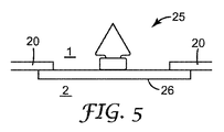
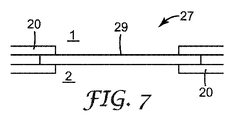
図5及び図6は、例証的な吸気又は呼気弁の概略断面図である。図7は、例証的な伝声板の概略断面図である。これらの吸気若しくは呼気弁、又は伝声板は、以下に説明する通り、剛性面体本体20の複数の開口部の内部に配置されるか又は開口部に隣接して配置される。
5 and 6 are schematic cross-sectional views of exemplary inspiratory or expiratory valves. FIG. 7 is a schematic cross-sectional view of an illustrative message board. These inhalation or exhalation valves or the sound transmission plate are arranged inside the plurality of openings of the
図5は、例証的な呼吸保護マスク10の外部領域1又は2と、内部領域2又は1との間に配置された板状弁体部分概略図を図示している。板26が剛性面体本体20と、ユーザーの顔面又は例証的な呼吸保護マスク10の内部領域2との間に配置されているとき、板25は吸気板である。板26が剛性面体本体20と、例証的な呼吸保護マスク10の外部領域1との間に配置されているとき、板25は呼気板である。図6は、吸気5又は呼気5を板26と弁本体又は剛性面体本体20との間に通過させる、板状弁体を図示している。
FIG. 5 illustrates a plate-like valve element partial schematic view disposed between the
図7は、伝声板27の部分概略図を図示している。例証的な伝声板27は、剛性面体本体20又は伝声板本体の部分に固定された板29を包含する。伝声板29は、例証的な呼吸保護マスク10の外部領域1又は2と内部領域2又は1との間に配置される。伝声板27は、言葉を呼吸保護マスク10のユーザーから伝達するのを補助する。
FIG. 7 illustrates a partial schematic diagram of the
図2は、レスピレータ保護マスク10用の例証的な剛性面体本体20の斜視図である。剛性面体本体20は、第1表面21及び第2表面22を包含する。図示された実施形態では、第1表面21及び第2表面22は、本体の厚みT(図4参照)により隔てられた、剛性面体本体20の対向する主表面である。図示された実施形態では、第1表面21は、(環境に向いた)外側表面であり、第2表面22は、(ユーザーの顔面に向いた)内側表面である。例示した剛性面体本体20は、例えば、1つの鼻開口部16及び2つの頬開口部18など、複数の開口部又はポートを包含する。板(図示せず)を包含する少なくとも1つの吸気弁、及び板(図示せず)を包含する1つの呼気弁が、複数のポート又は開口部内部に配置され、図示した剛性面体本体20を形成する。幾つかの実施形態では、伝声板が、複数のポート又は開口部の1つ以上の内部に配置され、図示した剛性面体本体20を形成する。
FIG. 2 is a perspective view of an illustrative
多くの実施形態では、1つ以上の開口23が、本体の厚みTを通って延在する。呼吸保護用複合面体11のオーバーモールド製造の間に、(シリコーンシール面体要素12を形成する)液状シリコーンは、1つ以上の開口23内を流れ、シリコーンシール面体要素12と剛性面体本体20との間に機械的連結を形成する。幾つかの実施形態では、吸気弁は、化学的又は粒子状濾過カートリッジ取付け要素29を包含する。多くの実施形態では、取付け要素29は、化学的又は粒子状濾過カートリッジ取付け要素29上の相補要素と噛合う差し込み式取付け要素である。差し込み式取付けシステムは、2つ部分を共に取り付けるために構成され、この場合、2つの部分は主にねじ山以外の要素を包含し、2つの部分は、一方の部分を少なくとも部分的に他方の部分内に挿入し、2つの部分を複数回転させずに接合できるように一方の部分を他方の部分に対して回転させることにより取り付けられるようになっている。
In many embodiments, one or
図3は、図2に示した剛性面体本体20の斜視正面図であり、シリコーンシール面体要素12が剛性面体本体20の半分の上にオーバーモールドされた状態である。図4は、図2に示した剛性面体本体の斜視背面図であり、シリコーンシール面体要素が剛性面体本体の半分の上にオーバーモールドされた状態である。代表的な呼吸保護用複合面体11は、剛性面体本体20の両半分の上にオーバーモールドされたシリコーンシール面体要素12を包含するが、シリコーンシール面体要素12の輪郭を更に容易に図示するために、シリコーンシール面体要素12の横断面として示されていることを理解されたい。
3 is a perspective front view of the
剛性面体本体20については上記に説明した。シリコーンシール面体要素12は、第1表面21及び第2表面22の少なくとも一方など、剛性面体本体20の第1表面及び第2表面の少なくとも一方に化学的に結合される。多くの実施形態では、シリコーンシール面体要素12は、第1表面21及び第2表面22の少なくとも一方に化学的に結合され、この場合、第1表面21及び第2表面22は、上記のように、本体の厚みTにより隔てられた、剛性面体本体20の主表面である。
The
呼吸保護用複合面体11のオーバーモールド製造の間に、(シリコーンシール面体要素12を形成する)液状シリコーンは、1つ以上の開口23内を流れ、いったん液状シリコーンがその固体状態に硬化されると、シリコーンシール面体要素12と剛性面体本体20との間に機械的連結を形成する。
During overmolding of the respiratory protective
図8は、液状シリコーンが剛性面体本体20を通る開口23を相互に貫通し合うときに生じる機械的連結を図示する、呼吸保護用複合面体11の部分の概略断面図を図示している。シリコーンシール面体要素12は、第1表面21及び第2表面22上に配置され、第1表面21及び第2表面22に化学的に結合され、この場合、第1表面21及び第2表面22は、上記のように、本体の厚みTにより隔てられた、剛性面体本体20の主表面である。
FIG. 8 illustrates a schematic cross-sectional view of a portion of the respiratory protection
再び図3及び図4を参照すると、シリコーンシール面体要素12は、ユーザーの頭部又は顔面と剛性面体本体20との間に気密シールを形成するように構成される。用語「気密シール」とは、未濾過空気又は周囲空気が連結境界面において呼吸保護用複合面体11の内部に進入するのを実質的に防止する、ユーザーの顔面又は頭部に対するシリコーンシール面体要素12の連結を指す。図示したシリコーンシール面体要素12は、ユーザーの顔面に接触する内曲した羽状カフ14を包含する。
Referring again to FIGS. 3 and 4, the silicone
真空漏れ試験を用いて気密性が測定される。試験装置は、3つのポートを備えた密閉チャンバからなる。チャンバの体積はおよそ750cm3である。3つのポートのうちの1つには、レスピレータ取付け構成要素がその差し込み式取付け要素により固定される。装置の第2ポートには、チャンバの内部と周囲空気との間の圧力差を(少なくとも25cm水柱まで)測定できる真空計が取り付けられる。第3ポートには、真空源が遮断弁を介して取り付けられる。試験を実施するには、遮断弁を開き、真空源のスイッチを入れて、チャンバから(真空計に示される通り)大気圧より低い25cm水柱の圧力まで排気する。次に遮断弁を閉じ、真空源のスイッチを切る。チャンバ内部の真空レベルを60秒間観測する。内側に空気が漏れることによりチャンバ内部の圧力が増大し、これにより真空レベルが低減する。本発明に関して、チャンバと周囲空気との間の圧力差は、60秒後に15cm水柱超過である。より好ましくは、圧力差は、60秒後に24cm水柱を超えた状態を維持する。 Airtightness is measured using a vacuum leak test. The test apparatus consists of a sealed chamber with three ports. The chamber volume is approximately 750 cm 3 . In one of the three ports, a respirator mounting component is secured by its plug-in mounting element. The second port of the device is fitted with a vacuum gauge that can measure the pressure difference between the interior of the chamber and the ambient air (up to a 25 cm water column). A vacuum source is attached to the third port via a shut-off valve. To perform the test, open the shut-off valve, switch on the vacuum source, and evacuate the chamber (as indicated on the gauge) to a pressure of 25 cm water column below atmospheric pressure. Then close the shut-off valve and switch off the vacuum source. The vacuum level inside the chamber is observed for 60 seconds. Air leakage to the inside increases the pressure inside the chamber, thereby reducing the vacuum level. In the context of the present invention, the pressure difference between the chamber and ambient air is over 15 cm of water after 60 seconds. More preferably, the pressure difference remains above the 24 cm water column after 60 seconds.
呼吸保護用複合面体11は、熱硬化性シリコーン材料を熱可塑性剛性面体本体20上にオーバーモールドすることによって形成され得る。熱硬化性シリコーン材料は、熱可塑性剛性面体本体20に化学結合(即ち、共有結合)する。
The respiratory protection
用語「化学結合又は化学的に結合された」は、原子及び分子の間の引力相互作用を担う物理過程を指し、共有結合及びイオン結合、並びに水素及びファンデルワールス結合を包含し、多くの場合、剛性面体本体20表面上の利用可能な官能基、及びそれらの熱硬化性シリコーン材料との反応性に依存し得る。多くの実施形態では、熱硬化性シリコーン材料は、熱可塑性剛性面体本体20の前処理が不要であるように選択される。換言すれば、熱硬化性シリコーン材料は、熱可塑性剛性面体本体20に対して自己接着性である。熱硬化性シリコーン材料は、多くの場合、オーバーモールドプロセス中に、熱硬化性シリコーン材料を硬化させるのに十分な温度ではあるが、熱可塑性剛性面体本体20のガラス転移温度より低い温度まで熱硬化性シリコーン材料を硬化させるために加熱される。
The term “chemically or chemically bonded” refers to a physical process responsible for attractive interactions between atoms and molecules, including covalent and ionic bonds, and hydrogen and van der Waals bonds, and often Depending on the available functional groups on the surface of the
以下の実施例に示すように、化学結合のレベルは、平均的な破損に至る力の試験方法によって決定され得る。多くの実施形態では、平均的な破損に至る力は、25N以上、又は50N以上、又は100N以上、又は150N以上、又は200N以上、又は300N以上である。 As shown in the examples below, the level of chemical bonding can be determined by a test method of force leading to average failure. In many embodiments, the average force leading to failure is 25N or higher, or 50N or higher, or 100N or higher, or 150N or higher, or 200N or higher, or 300N or higher.
熱可塑性剛性面体本体20は、任意の有用な熱可塑性材料から形成され得る。多くの実施形態では、熱可塑性剛性面体本体20は、ポリアミド(例えばナイロン)、ポリカーボネート、ポリブチレン−テレフタレート、ポリフェニルオキシド、ポリフタルアミド、又はこれらの混合物から形成される。
The thermoplastic
いずれかの有用な熱硬化性液状シリコーンゴム又は材料を利用して、シリコーンシール面体要素12を形成し得る。液状シリコーンゴムは、低い圧縮永久歪み、高い安定性、並びに熱及び冷気の極端な温度に耐える能力を有する、高純度プラチナ硬化シリコーンである。材料の熱硬化性の性質のために、液状シリコーン射出成形は多くの場合、材料を加熱空洞に、内に押し込んで加硫する前に材料を低温に維持する一方で、集中的に分配混合する(intensive distributive mixing)など、特殊処理を必要とする。シリコーンゴムは、交互のシリコーン及び酸素原子の主鎖、並びにメチル又はビニル側基を有する熱硬化性エラストマーの族である。シリコーンゴムは、広範囲の温度に亘ってその機械的特性を維持し、シリコーンゴムにおけるメチル基の存在により、これらの材料は疎水性となる。
Any useful thermoset liquid silicone rubber or material may be utilized to form the silicone
例証的な熱硬化性シリコーン材料としては、商品名:エラストシル(ELASTOSIL)LR 3070(ワッカーシリコーン(Wacker-Silicones)、ドイツ、ミュンヘン(Munich));KE2095又はKE2009シリーズ(例えばKE2095−60、KE2095−50、KE2095−40など)又はX−34−1547A/B、X−34−1625A/B、X−34−1625A/B(全て信越化学工業株式会社(Shin-Etsu Chemical Co., LTD.)(日本))で入手可能な自己接着性液状シリコーンゴムが挙げられる。これらの自己接着性液状シリコーンゴムは、液状シリコーンゴムを熱可塑性表面に化学結合させるために、特定の熱可塑性表面の前処理を必要としない。 Illustrative thermosetting silicone materials include: ELASTOSIL LR 3070 (Wacker-Silicones, Munich, Germany); KE2095 or KE2009 series (eg KE2095-60, KE2095-50) , KE2095-40, etc.) or X-34-1547A / B, X-34-1625A / B, X-34-1625A / B (all Shin-Etsu Chemical Co., LTD.) (Japan) )) And self-adhesive liquid silicone rubber. These self-adhesive liquid silicone rubbers do not require a specific thermoplastic surface pretreatment in order to chemically bond the liquid silicone rubber to the thermoplastic surface.
シリコーンゴムと熱可塑性材料の好適な組み合わせを確認するために、幾つかの試験が用いられた。特に興味深いのは、シリコーンゴムと熱可塑性材料との間の結合の強度であり、これは、気密シールの耐久性に影響を及ぼす。 Several tests were used to identify suitable combinations of silicone rubber and thermoplastic material. Of particular interest is the strength of the bond between the silicone rubber and the thermoplastic material, which affects the durability of the hermetic seal.
熱可塑性材料を用いて長さ51mm、幅25mm、及び厚さ2mmの平坦な剛性基材片を成形することにより、試験用ストリップを準備する。次に、基材の一端のうちの6mmが第2金型の空洞内に突出するように、基材を第2金型内に固定する。第2金型の空洞は、幅27mm及び長さ49mmである。金型の深さは2mmであり、突出した基材端部の直近において4mmまで広がり、シリコーンが金型空洞内に注入されるとき、シリコーンが、突出した基材端部の全ての側面上に厚さ1mmの層を形成するようになっている。その結果、生じる試験用ストリップは長さ94mmであり、一方の端部上に剛性熱可塑性基材片、他方の端部上にシリコーンゴムを有する。 A test strip is prepared by molding a flat rigid substrate piece 51 mm long, 25 mm wide and 2 mm thick using a thermoplastic material. Next, the substrate is fixed in the second mold so that 6 mm of one end of the substrate protrudes into the cavity of the second mold. The cavity of the second mold has a width of 27 mm and a length of 49 mm. The depth of the mold is 2 mm and extends to 4 mm in the immediate vicinity of the protruding substrate edge, and when silicone is injected into the mold cavity, the silicone is on all sides of the protruding substrate edge. A layer having a thickness of 1 mm is formed. The resulting test strip is 94 mm long and has a rigid thermoplastic substrate piece on one end and silicone rubber on the other end.
基材材料とシリコーンとの間の結合の強度は、MTSモデル858材料試験システム(Material Test System)(MTSシステムズ社(MTS Systems Corporation)、ミネソタ州イーデンプレーリー(Eden Prairie))のような機械試験機のつかみ具に試験用ストリップの2つの端部を把持し、試験用ストリップが破断するまで伸張し、破損が起きた力を記録することにより測定される。破損に至る力の実施例が表1に示される。実施例1〜4は、材料の適切な組み合わせにより、300Nを超える結合強度を達成し得ることを示している。比較例C1及びC2に関して、シリコーンは熱可塑性材料に結合しなかった。 The strength of the bond between the substrate material and the silicone is determined by a mechanical testing machine such as the MTS Model 858 Material Test System (MTS Systems Corporation, Eden Prairie, MN). The grip is measured by gripping the two ends of the test strip, stretching until the test strip breaks, and recording the force at which the failure occurred. Examples of forces leading to breakage are shown in Table 1. Examples 1-4 show that with appropriate combinations of materials, bond strengths in excess of 300N can be achieved. For Comparative Examples C1 and C2, the silicone did not bond to the thermoplastic material.

ダウ(Dow)LC−70−2004シリコーンは、ダウ・コーニング社(Dow Corning Corporation)(ミシガン州ミッドランド(Midland))により製造され、RTPナイロン6/6は、RTP社(RTP Company)(ミネソタ州ウィノーナ(Winona))により製造されるポリアミドであり、ザイテル(Zytel)PAは、イー・アイ・デュポン・ド・ヌムール(E.I. du Pont de Nemours)(デラウェア州ウィルミントン(Wilmington))により製造されるポリアミドである。 Dow LC-70-2004 silicone is manufactured by Dow Corning Corporation (Midland, Michigan) and RTP nylon 6/6 is RTP Company (Winona, MN). Zytel PA is a polyamide manufactured by EI du Pont de Nemours (Wilmington, Delaware). is there.
このように、熱硬化性エラストマーフェースシールを備えたレスピレータ面体の実施形態が開示される。本発明は、開示されたもの以外の実施形態でも実施可能であることを当業者は理解するであろう。開示された実施形態は、例証の目的で提示されているのであって、制限するものではなく、本発明は、次に続く請求項によってのみ限定される。 Thus, an embodiment of a respirator face with a thermoset elastomer face seal is disclosed. Those skilled in the art will appreciate that the invention may be practiced with embodiments other than those disclosed. The disclosed embodiments are presented for purposes of illustration and not limitation, and the invention is limited only by the claims that follow.
Claims (3)
前記第1表面及び前記第2表面の少なくとも一方に化学結合した熱硬化性液状シリコーンシール面体要素と、を含み、
前記化学結合は、少なくとも100Nの平均的な破損に至る力によって、特徴付けられており、
前記高分子剛性面体本体の部分は、吸気弁と、該吸気弁に取り付けられた濾過カートリッジと、を含んでおり、
前記シリコーンシール面体要素は、前記濾過カートリッジと前記高分子剛性面体本体の部分との間にガスケットを形成している、呼吸保護用複合面体。 A polymeric rigid face body comprising a thermoplastic material comprising polyamide and having a first surface and a second surface;
A thermosetting liquid silicone sealing facepiece element chemically bonded to at least one of the first surface and the second surface;
The chemical bond is characterized by a force leading to an average break of at least 100 N ;
The portion of the polymer rigid face body includes an intake valve and a filtration cartridge attached to the intake valve.
The silicone sealing facepiece element, the filtration cartridge and that form a gasket between the polymeric rigid facepiece body portion, respiratory protection composite facepiece.
熱硬化性液状シリコーンを、ポリアミドからなる熱可塑性材料を含み、且つ、第1表面及び第2表面を有する高分子剛性面体本体上に、オーバーモールドするステップであって、前記液状シリコーンが前記第1表面又は前記第2表面の少なくとも一方と接触する、ステップと、
前記液状シリコーンを固化させて、前記第1表面又は前記第2表面の少なくとも一方に化学結合するシリコーンシール面体要素を形成し、呼吸保護用複合面体要素を形成するステップと、を含み、
前記化学結合は、少なくとも100Nの平均的な破損に至る力によって、特徴付けられており、
前記高分子剛性面体本体の部分は、吸気弁と、該吸気弁に取り付けられた濾過カートリッジと、を含んでおり、
前記シリコーンシール面体要素は、前記濾過カートリッジと前記高分子剛性面体本体の部分との間にガスケットを形成している、方法。 A method of forming a respiratory protection composite face,
A step of overmolding a thermosetting liquid silicone onto a polymer rigid face body including a thermoplastic material made of polyamide and having a first surface and a second surface, wherein the liquid silicone is the first Contacting at least one of a surface or the second surface;
Solidifying the liquid silicone to form a silicone sealing face element that chemically bonds to at least one of the first surface or the second surface to form a respiratory protection composite face element;
The chemical bond is characterized by a force leading to an average break of at least 100 N ;
The portion of the polymer rigid face body includes an intake valve and a filtration cartridge attached to the intake valve.
The silicone sealing facepiece element that form a gasket between the filter cartridge and the polymeric rigid facepiece body portion.
Applications Claiming Priority (3)
| Application Number | Priority Date | Filing Date | Title |
|---|---|---|---|
| US99974107P | 2007-08-31 | 2007-08-31 | |
| US60/999,741 | 2007-08-31 | ||
| PCT/US2008/070803 WO2009029363A1 (en) | 2007-08-31 | 2008-07-23 | Respirator facepiece with thermoset elastomeric face seal |
Related Child Applications (1)
| Application Number | Title | Priority Date | Filing Date |
|---|---|---|---|
| JP2013209518A Division JP5770807B2 (en) | 2007-08-31 | 2013-10-04 | Respirator face with thermoset elastomer face seal |
Publications (3)
| Publication Number | Publication Date |
|---|---|
| JP2010537723A JP2010537723A (en) | 2010-12-09 |
| JP2010537723A5 JP2010537723A5 (en) | 2011-09-01 |
| JP5669578B2 true JP5669578B2 (en) | 2015-02-12 |
Family
ID=39816952
Family Applications (3)
| Application Number | Title | Priority Date | Filing Date |
|---|---|---|---|
| JP2010523002A Expired - Fee Related JP5669578B2 (en) | 2007-08-31 | 2008-07-23 | Respirator face with thermoset elastomer face seal |
| JP2013209518A Expired - Fee Related JP5770807B2 (en) | 2007-08-31 | 2013-10-04 | Respirator face with thermoset elastomer face seal |
| JP2015093520A Active JP5968496B2 (en) | 2007-08-31 | 2015-04-30 | Respirator face with thermoset elastomer face seal |
Family Applications After (2)
| Application Number | Title | Priority Date | Filing Date |
|---|---|---|---|
| JP2013209518A Expired - Fee Related JP5770807B2 (en) | 2007-08-31 | 2013-10-04 | Respirator face with thermoset elastomer face seal |
| JP2015093520A Active JP5968496B2 (en) | 2007-08-31 | 2015-04-30 | Respirator face with thermoset elastomer face seal |
Country Status (11)
| Country | Link |
|---|---|
| US (1) | US8820326B2 (en) |
| EP (1) | EP2183032B1 (en) |
| JP (3) | JP5669578B2 (en) |
| KR (1) | KR101555721B1 (en) |
| CN (2) | CN104524707B (en) |
| AU (1) | AU2008293824B2 (en) |
| BR (1) | BRPI0815256B8 (en) |
| ES (1) | ES2675754T4 (en) |
| PL (1) | PL2183032T3 (en) |
| RU (1) | RU2429034C1 (en) |
| WO (1) | WO2009029363A1 (en) |
Families Citing this family (39)
| Publication number | Priority date | Publication date | Assignee | Title |
|---|---|---|---|---|
| AU2008293810B2 (en) | 2007-08-31 | 2011-10-06 | 3M Innovative Properties Company | Unitary respirator with molded thermoset elastomeric elements |
| SE534951C2 (en) * | 2010-06-18 | 2012-02-28 | Facecover Sweden Ab | Motor-driven Air Purifying Respirator (PAPR) |
| US20120125341A1 (en) * | 2010-11-19 | 2012-05-24 | 3M Innovative Properties Company | Filtering face-piece respirator having an overmolded face seal |
| US9408424B2 (en) * | 2013-01-10 | 2016-08-09 | 3M Innovative Properties Company | Filtering face-piece respirator having a face seal comprising a water-vapor-breathable layer |
| US9950202B2 (en) | 2013-02-01 | 2018-04-24 | 3M Innovative Properties Company | Respirator negative pressure fit check devices and methods |
| US9517367B2 (en) | 2013-02-01 | 2016-12-13 | 3M Innovative Properties Company | Respiratory mask having a clean air inlet chamber |
| US11052268B2 (en) | 2013-02-01 | 2021-07-06 | 3M Innovative Properties Company | Respirator negative pressure fit check devices and methods |
| GB201314884D0 (en) | 2013-08-20 | 2013-10-02 | 3M Innovative Properties Co | Personal respiratory protection device |
| GB201314886D0 (en) | 2013-08-20 | 2013-10-02 | 3M Innovative Properties Co | Personal respiratory protection device |
| GB201314887D0 (en) | 2013-08-20 | 2013-10-02 | 3M Innovative Properties Co | Personal respiratory protection device |
| GB201314885D0 (en) | 2013-08-20 | 2013-10-02 | 3M Innovative Properties Co | Personal respiratory protection device |
| USD778430S1 (en) * | 2013-11-15 | 2017-02-07 | 3M Innovative Properties Company | Filter cartridge |
| KR200489143Y1 (en) * | 2014-01-17 | 2019-05-07 | 쓰리엠 이노베이티브 프로퍼티즈 캄파니 | Respiratory protection mask |
| CN103706056A (en) * | 2014-02-02 | 2014-04-09 | 叶林森 | Combined external nasal air purification device |
| USD745962S1 (en) * | 2014-05-22 | 2015-12-22 | 3M Innovative Properties Company | Respirator filter retainer |
| USD757928S1 (en) * | 2014-05-22 | 2016-05-31 | 3M Innovative Properties Company | Respirator cartridge body |
| USD757247S1 (en) * | 2014-05-22 | 2016-05-24 | 3M Innovative Properties Company | Respirator cartridge |
| USD744088S1 (en) * | 2014-05-22 | 2015-11-24 | 3M Innovative Properties Company | Respirator mask having a circular button |
| USD746438S1 (en) * | 2014-05-22 | 2015-12-29 | 3M Innovative Properties Company | Respirator filter cover |
| AU362443S (en) * | 2015-01-14 | 2015-07-07 | Jsp Ltd | Respiratory mask component |
| USD743536S1 (en) * | 2015-02-27 | 2015-11-17 | 3M Innovative Properties Company | Respirator mask having a circular button |
| USD763437S1 (en) * | 2015-02-27 | 2016-08-09 | 3M Innovative Properties Company | Respirator cartridge body |
| USD762845S1 (en) * | 2015-02-27 | 2016-08-02 | 3M Innovative Properties Company | Respirator cartridge |
| EP3365075A4 (en) | 2015-10-22 | 2019-05-15 | Scott Technologies, Inc. | Respirator mask with voice transmittal feature |
| US10918894B2 (en) | 2015-10-22 | 2021-02-16 | Scott Technologies, Inc. | Face seal for respirator mask |
| USD827810S1 (en) | 2016-03-28 | 2018-09-04 | 3M Innovative Properties Company | Hardhat suspension adapter for half facepiece respirators |
| WO2017172358A1 (en) | 2016-03-28 | 2017-10-05 | 3M Innovative Properties Company | Respirator fit check sealing devices and methods |
| USD842982S1 (en) | 2016-03-28 | 2019-03-12 | 3M Innovative Properties Company | Hardhat suspension adapter for half facepiece respirators |
| EP3436163B1 (en) | 2016-03-28 | 2020-08-19 | 3M Innovative Properties Company | Multiple chamber respirator sealing devices and methods |
| USD816209S1 (en) | 2016-03-28 | 2018-04-24 | 3M Innovative Properties Company | Respirator inlet port connection seal |
| CN106853273A (en) * | 2017-03-08 | 2017-06-16 | 成都凯力科技有限公司 | A kind of filter face mask |
| EP3781272B1 (en) * | 2018-04-18 | 2023-01-04 | 3M Innovative Properties Company | Dual-molded polyamide-silicone composite article and methods of making |
| US20230201408A1 (en) * | 2020-04-23 | 2023-06-29 | Cedarz Group, LLP | Electronic Breathing Mask with UVC Air Purification System and Peripherals |
| GB2597641B (en) * | 2020-06-16 | 2023-02-08 | Airgill Ltd | Adjustable face mask |
| DE102020126815A1 (en) | 2020-09-30 | 2022-03-31 | Manuel Pescher | Breathing mask, its use and method |
| TWI750834B (en) * | 2020-10-05 | 2021-12-21 | 曹樹德 | Face mask |
| CA199994S (en) * | 2020-12-15 | 2022-07-11 | Dentec Safety Specialists Inc | Respirator |
| CA200196S (en) * | 2020-12-22 | 2022-06-13 | Dentec Safety Specialists Inc | Respirator |
| WO2023173063A2 (en) * | 2022-03-11 | 2023-09-14 | Teal Bio, Inc. | High-filtration reusable face mask with textured contact portion and various coupling mechanisms |
Family Cites Families (45)
| Publication number | Priority date | Publication date | Assignee | Title |
|---|---|---|---|---|
| GB1360632A (en) * | 1972-01-06 | 1974-07-17 | Roberts Ltd S F | Face masks |
| US4414973A (en) * | 1981-03-10 | 1983-11-15 | U.S.D. Corp. | Respirator face mask |
| JPS60143917A (en) | 1983-12-29 | 1985-07-30 | Shin Etsu Polymer Co Ltd | Manufacture of different kind silicon rubber molding product |
| JPS63180058A (en) | 1987-01-21 | 1988-07-25 | 松下冷機株式会社 | Refrigerator |
| US4790306A (en) * | 1987-09-25 | 1988-12-13 | Minnesota Mining And Manufacturing Company | Respiratory mask having a rigid or semi-rigid, insert-molded filtration element and method of making |
| US5062421A (en) * | 1987-11-16 | 1991-11-05 | Minnesota Mining And Manufacturing Company | Respiratory mask having a soft, compliant facepiece and a thin, rigid insert and method of making |
| US4886058A (en) * | 1988-05-17 | 1989-12-12 | Minnesota Mining And Manufacturing Company | Filter element |
| US5111821A (en) * | 1988-11-08 | 1992-05-12 | Health Research, Inc. | Fluorometric method for detecting abnormal tissue using dual long-wavelength excitation |
| FR2644549B1 (en) * | 1989-03-16 | 1991-07-05 | Hutchinson | DISCHARGE VALVE DEVICE, PARTICULARLY FOR A FLUID CIRCUIT ASSOCIATED WITH AN AEROTHERM |
| US4910806A (en) * | 1989-05-01 | 1990-03-27 | Innovative Scuba Concepts, Inc. | Adjustable strap for use with a diver's face mask |
| JP2580913B2 (en) * | 1991-10-23 | 1997-02-12 | 信越化学工業株式会社 | Thermoplastic resin-silicone rubber molded article and method for producing the same |
| WO1993024181A1 (en) * | 1992-05-29 | 1993-12-09 | Minnesota Mining And Manufacturing Company | Unidirectional fluid valve |
| US7117868B1 (en) * | 1992-05-29 | 2006-10-10 | 3M Innovative Properties Company | Fibrous filtration face mask having a new unidirectional fluid valve |
| US5325892A (en) * | 1992-05-29 | 1994-07-05 | Minnesota Mining And Manufacturing Company | Unidirectional fluid valve |
| GB2275614A (en) | 1993-03-03 | 1994-09-07 | Michael Beard | Seal for respiratory mask |
| WO1995009676A1 (en) | 1993-10-01 | 1995-04-13 | Minnesota Mining And Manufacturing Company | Speech transmission adaptor for use with a respirator mask |
| US5456027A (en) * | 1994-04-08 | 1995-10-10 | Vincent G. Tecchio | Athletic shoe with a detachable sole having an electronic breakaway system |
| US6216693B1 (en) * | 1995-01-20 | 2001-04-17 | 3M Innovative Properties Company | Respirator having a compressible press fir filter element |
| US5592935A (en) * | 1995-05-03 | 1997-01-14 | Minnesota Mining And Manufacturing Company | Positive/negative air pressure adaptor for use with respirators |
| US5689833A (en) | 1995-05-03 | 1997-11-25 | Minnesota Mining And Manufacturing Company | Eye shield for a respiratory mask |
| US5592937A (en) * | 1995-06-07 | 1997-01-14 | Mine Safety Appliances Company | Respirator mask with stiffening elements |
| US6298841B1 (en) * | 1995-06-19 | 2001-10-09 | Richard T. Cheng | Paintball gun and light emitting projectile-type ammunition for use therewith |
| JP3011642B2 (en) * | 1995-08-31 | 2000-02-21 | 信越ポリマー株式会社 | Thermosetting resin composition, composite molded article using the same, and cover member for push button switch |
| US6176239B1 (en) * | 1997-08-06 | 2001-01-23 | The United States Of America As Represented By The Secretary Of The Army | Advanced chemical-biological mask |
| US6016804A (en) * | 1997-10-24 | 2000-01-25 | Scott Technologies, Inc. | Respiratory mask and method of making thereof |
| FR2784298B1 (en) * | 1998-10-13 | 2001-01-19 | Taema | NASAL RESPIRATORY MASK FOR THE TREATMENT OF RESPIRATORY DISORDERS, ESPECIALLY SLEEP APNEA |
| JP2000167075A (en) | 1999-02-09 | 2000-06-20 | Shigematsu Works Co Ltd | Phosphorescent full-face mask |
| US6298849B1 (en) * | 1999-10-14 | 2001-10-09 | Moldex-Metric, Inc. | Respirator mask with snap in filter cartridge |
| EP1274486A2 (en) * | 2000-04-17 | 2003-01-15 | Scott Technologies, Inc. | Respiratory mask and service module |
| CA2625243C (en) * | 2000-04-18 | 2009-04-14 | Avon Protection Systems, Inc. | Self-sealing filter connection and gas mask and filter assembly incorporating the same |
| US20020020416A1 (en) * | 2000-08-11 | 2002-02-21 | David Namey | Two-shot injection molded nasal/oral mask |
| DE10101772A1 (en) * | 2001-01-17 | 2002-07-18 | Bayer Ag | Low-stress composite component |
| US7849856B2 (en) * | 2001-06-25 | 2010-12-14 | 3M Innovative Properties Company | Respirator valve |
| US6689144B2 (en) * | 2002-02-08 | 2004-02-10 | Scimed Life Systems, Inc. | Rapid exchange catheter and methods for delivery of vaso-occlusive devices |
| US20030168063A1 (en) * | 2002-03-08 | 2003-09-11 | Gambone Anthony Joseph | Pressure face mask and nasal mask |
| JP2003330296A (en) | 2002-05-13 | 2003-11-19 | Shin Etsu Chem Co Ltd | Liquid addition curing type silicone rubber composition for belt for fixing toner |
| JP2004331820A (en) * | 2003-05-08 | 2004-11-25 | Shin Etsu Chem Co Ltd | Silicone rubber adhesive composition for mobile object |
| US7650884B2 (en) | 2003-11-21 | 2010-01-26 | 3M Innovative Properties Company | Respiratory facepiece and method of making a facepiece using separate molds |
| WO2005063326A1 (en) | 2003-12-31 | 2005-07-14 | Resmed Limited | Mask system |
| US8127764B2 (en) * | 2004-11-05 | 2012-03-06 | Ric Investments Llc | Respiratory mask cushion and mask using same |
| ITGE20040108A1 (en) * | 2004-12-03 | 2005-03-03 | Htm Sport Spa | UNDERWATER MASK AND METHOD FOR ITS MANUFACTURE. |
| JP2006289093A (en) | 2005-04-12 | 2006-10-26 | Woorhitech Co Ltd | Multi-functional mask |
| AU2006272456A1 (en) * | 2005-07-19 | 2007-01-25 | Map Medizin-Technologie Gmbh | Respiratory mask and method for manufacturing a respiratory mask |
| US20080133001A1 (en) * | 2006-12-04 | 2008-06-05 | Nicast Ltd. | Plastically deformable compositions and uses thereof |
| KR100891305B1 (en) * | 2007-04-04 | 2009-04-06 | 엘지전자 주식회사 | Illumination device |
-
2008
- 2008-07-23 CN CN201410697527.4A patent/CN104524707B/en active Active
- 2008-07-23 KR KR1020107006793A patent/KR101555721B1/en active IP Right Grant
- 2008-07-23 JP JP2010523002A patent/JP5669578B2/en not_active Expired - Fee Related
- 2008-07-23 ES ES08796434.2T patent/ES2675754T4/en active Active
- 2008-07-23 AU AU2008293824A patent/AU2008293824B2/en not_active Ceased
- 2008-07-23 EP EP08796434.2A patent/EP2183032B1/en active Active
- 2008-07-23 RU RU2010103955/12A patent/RU2429034C1/en not_active IP Right Cessation
- 2008-07-23 CN CN200880104008A patent/CN101784306A/en active Pending
- 2008-07-23 WO PCT/US2008/070803 patent/WO2009029363A1/en active Application Filing
- 2008-07-23 BR BRPI0815256A patent/BRPI0815256B8/en active IP Right Grant
- 2008-07-23 US US12/670,528 patent/US8820326B2/en active Active
- 2008-07-23 PL PL08796434T patent/PL2183032T3/en unknown
-
2013
- 2013-10-04 JP JP2013209518A patent/JP5770807B2/en not_active Expired - Fee Related
-
2015
- 2015-04-30 JP JP2015093520A patent/JP5968496B2/en active Active
Also Published As
| Publication number | Publication date |
|---|---|
| JP5770807B2 (en) | 2015-08-26 |
| AU2008293824B2 (en) | 2012-02-09 |
| EP2183032A1 (en) | 2010-05-12 |
| KR20100076958A (en) | 2010-07-06 |
| JP5968496B2 (en) | 2016-08-10 |
| ES2675754T3 (en) | 2018-07-12 |
| BRPI0815256B8 (en) | 2018-08-14 |
| KR101555721B1 (en) | 2015-09-25 |
| CN101784306A (en) | 2010-07-21 |
| JP2015180257A (en) | 2015-10-15 |
| EP2183032B1 (en) | 2018-04-25 |
| WO2009029363A1 (en) | 2009-03-05 |
| JP2010537723A (en) | 2010-12-09 |
| RU2429034C1 (en) | 2011-09-20 |
| CN104524707A (en) | 2015-04-22 |
| BRPI0815256B1 (en) | 2018-06-05 |
| US8820326B2 (en) | 2014-09-02 |
| BRPI0815256A2 (en) | 2015-02-18 |
| JP2014057864A (en) | 2014-04-03 |
| ES2675754T4 (en) | 2018-09-14 |
| PL2183032T3 (en) | 2018-09-28 |
| AU2008293824A1 (en) | 2009-03-05 |
| CN104524707B (en) | 2018-11-13 |
| US20100206311A1 (en) | 2010-08-19 |
Similar Documents
| Publication | Publication Date | Title |
|---|---|---|
| JP5968496B2 (en) | Respirator face with thermoset elastomer face seal | |
| US11701528B2 (en) | Unitary respirator with molded thermoset elastomeric elements | |
| JP5255639B2 (en) | Respirator mounting component with molded thermoset elastomeric seal | |
| BRPI0815322B1 (en) | "RESPIRATOR CONNECTION COMPONENT AND RESPIRATORY PROTECTION MASK" |
Legal Events
| Date | Code | Title | Description |
|---|---|---|---|
| A521 | Request for written amendment filed |
Free format text: JAPANESE INTERMEDIATE CODE: A523 Effective date: 20110712 |
|
| A621 | Written request for application examination |
Free format text: JAPANESE INTERMEDIATE CODE: A621 Effective date: 20110712 |
|
| A977 | Report on retrieval |
Free format text: JAPANESE INTERMEDIATE CODE: A971007 Effective date: 20121016 |
|
| A131 | Notification of reasons for refusal |
Free format text: JAPANESE INTERMEDIATE CODE: A131 Effective date: 20121030 |
|
| A601 | Written request for extension of time |
Free format text: JAPANESE INTERMEDIATE CODE: A601 Effective date: 20130130 |
|
| A602 | Written permission of extension of time |
Free format text: JAPANESE INTERMEDIATE CODE: A602 Effective date: 20130206 |
|
| A521 | Request for written amendment filed |
Free format text: JAPANESE INTERMEDIATE CODE: A523 Effective date: 20130227 |
|
| A02 | Decision of refusal |
Free format text: JAPANESE INTERMEDIATE CODE: A02 Effective date: 20130604 |
|
| A601 | Written request for extension of time |
Free format text: JAPANESE INTERMEDIATE CODE: A601 Effective date: 20140910 |
|
| A602 | Written permission of extension of time |
Free format text: JAPANESE INTERMEDIATE CODE: A602 Effective date: 20140916 |
|
| A521 | Request for written amendment filed |
Free format text: JAPANESE INTERMEDIATE CODE: A523 Effective date: 20141009 |
|
| A61 | First payment of annual fees (during grant procedure) |
Free format text: JAPANESE INTERMEDIATE CODE: A61 Effective date: 20141216 |
|
| R150 | Certificate of patent or registration of utility model |
Ref document number: 5669578 Country of ref document: JP Free format text: JAPANESE INTERMEDIATE CODE: R150 |
|
| R250 | Receipt of annual fees |
Free format text: JAPANESE INTERMEDIATE CODE: R250 |
|
| R250 | Receipt of annual fees |
Free format text: JAPANESE INTERMEDIATE CODE: R250 |
|
| R250 | Receipt of annual fees |
Free format text: JAPANESE INTERMEDIATE CODE: R250 |
|
| R250 | Receipt of annual fees |
Free format text: JAPANESE INTERMEDIATE CODE: R250 |
|
| R250 | Receipt of annual fees |
Free format text: JAPANESE INTERMEDIATE CODE: R250 |
|
| LAPS | Cancellation because of no payment of annual fees |